1. Introduction
Systems for heating, ventilation, and air conditioning (HVAC) contribute significantly to the overall energy consumption of modern buildings. Some analyses show that up to 40% of energy could be saved by improved control strategies of such systems [
1]. In order to optimize the energy consumption of a building or to detect atypical behaviors, information on the energy flow within the HVAC system is required. For this purpose, fluid temperature and flow velocity must be obtained at distinctive points in the hydraulic circuit. These data are usually collected using invasive temperature and flow sensors. However, modifications of an existing hydraulic system are often not desirable or possible (e.g., due to legal matters). In this case, non-invasive clamp-on temperature sensors as well as ultrasonic (US) flow sensors can be used. Besides their high price, US flow sensors are less suitable for smaller pipe diameters. Searching for a promising alternative, we have studied the utilization of low-cost thermal flow sensors to hydraulic circuits with metal pipes.
According to the underlying physical principle, there are three different types of thermal flow sensors [
2,
3]:
Hot-wire or hot-film flow sensors, which exploit directly the cooling effect of the passing fluid on a heater. Here, the heater excess temperature (i.e., the difference between heater and fluid temperature) corresponds to the flow velocity.
Calorimetric flow sensors utilize the flow dependent asymmetry of the temperature profile around the heater. In this case, temperature sensors arranged around the heater are needed for a detection. Their temperature difference is a function of the flow velocity.
Time-of-flight (TOF) flow sensors measure the propagation of a heat pulse over a known distance between the heater and the temperature sensor located downstream of the heater.
Due to high thermal conductivity of metal pipes, the excess temperature along the pipe surface drops significantly with increasing distance from the heater, even if very high heating power is applied. Hence, calorimetric and TOF sensors are less suitable for non-invasive measurements on metal pipes. In the course of this feasibility study, we therefore concentrated on hot wire transduction and developed a prototype, which was tested on common copper pipes. In contrast to sophisticated error-prone US setups, this transduction principle suits for arbitrary pipe diameters and allows for an extremely simple design.
2. Sensor Design
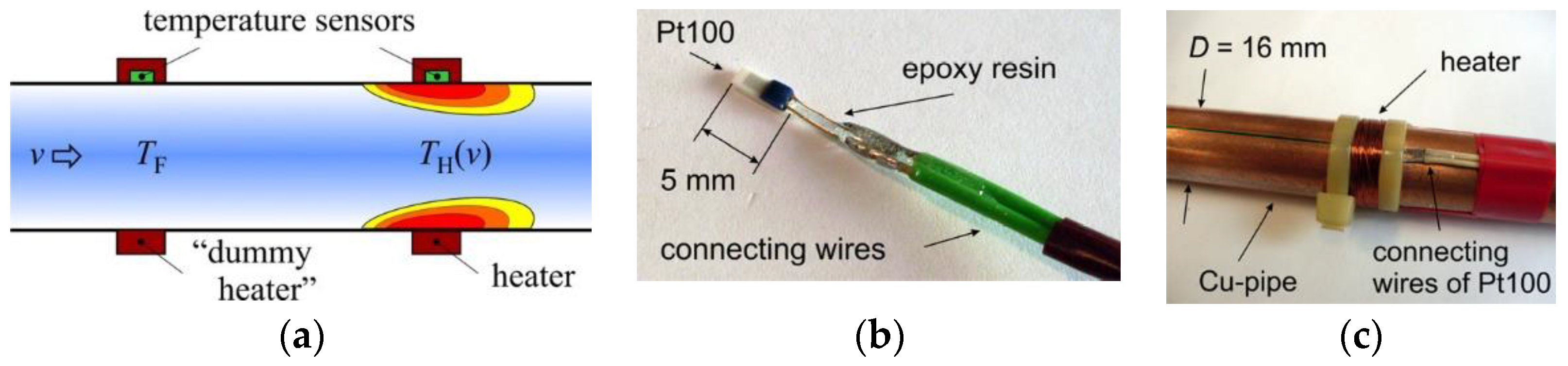
Figure 1a depicts a schematic cross section of the sensor. It consists of a heater and two Pt100 elements, which measure the fluid (
TF) and heater temperature (
TH). Their difference (i.e., the heater excess temperature
T =
TH −
TF) correlates with the mean flow velocity
v. For the sensor prototype, commercially available, miniaturized Pt100 elements were used (
Figure 1b). The first Pt100 element measuring the heater temperature (
TH) was placed on the copper pipe surface and fixed with cable ties. Subsequently, a thin copper wire was wound around it forming the heater, which was supplied by a constant electrical current (
Figure 1c). The second Pt100 element was positioned upstream of the heater at a distance of 5 cm to acquire the fluid temperature (
TF). Around this temperature sensor, the same heater structure was built, however, without supplying it with electrical current. This ʺdummy heaterʺ therefore does not influence a temperature field, but significantly reduces transient response after sudden variations of fluid temperature, since both temperature sensors feature approximately the same thermal mass. Finally, the whole pipe was insulated from the ambient.
3. FEM Simulations
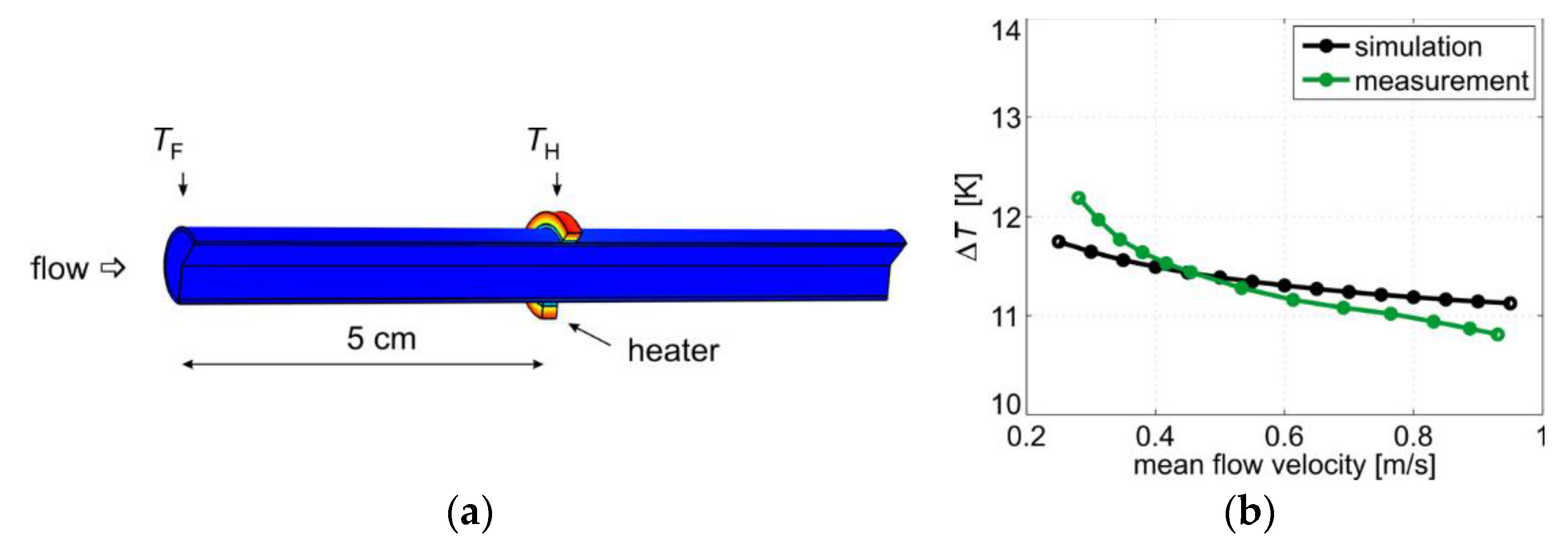
In order to analyze the flow conversion, a finite element method (FEM) model of the sensor was implemented (
Figure 2a). The dimensions of the simulated Cu-pipe are the same as for the prototype (16 mm diameter and 1 mm wall thickness). The sensor surface is considered to be ideally isolated from the ambient (adiabatic boundary condition). A constant heating power was induced at the heater and the temperature was recorded at the pipe surface below the heater (
TH) as well as 5 cm upstream of the heater (
TF).
Figure 2b shows the simulated heater excess temperature as a function of the mean flow velocity in the pipe as well as the actual measurement results obtained by means of the sensor prototype.
4. Sensor Electronics
The dynamic of the excess temperature in
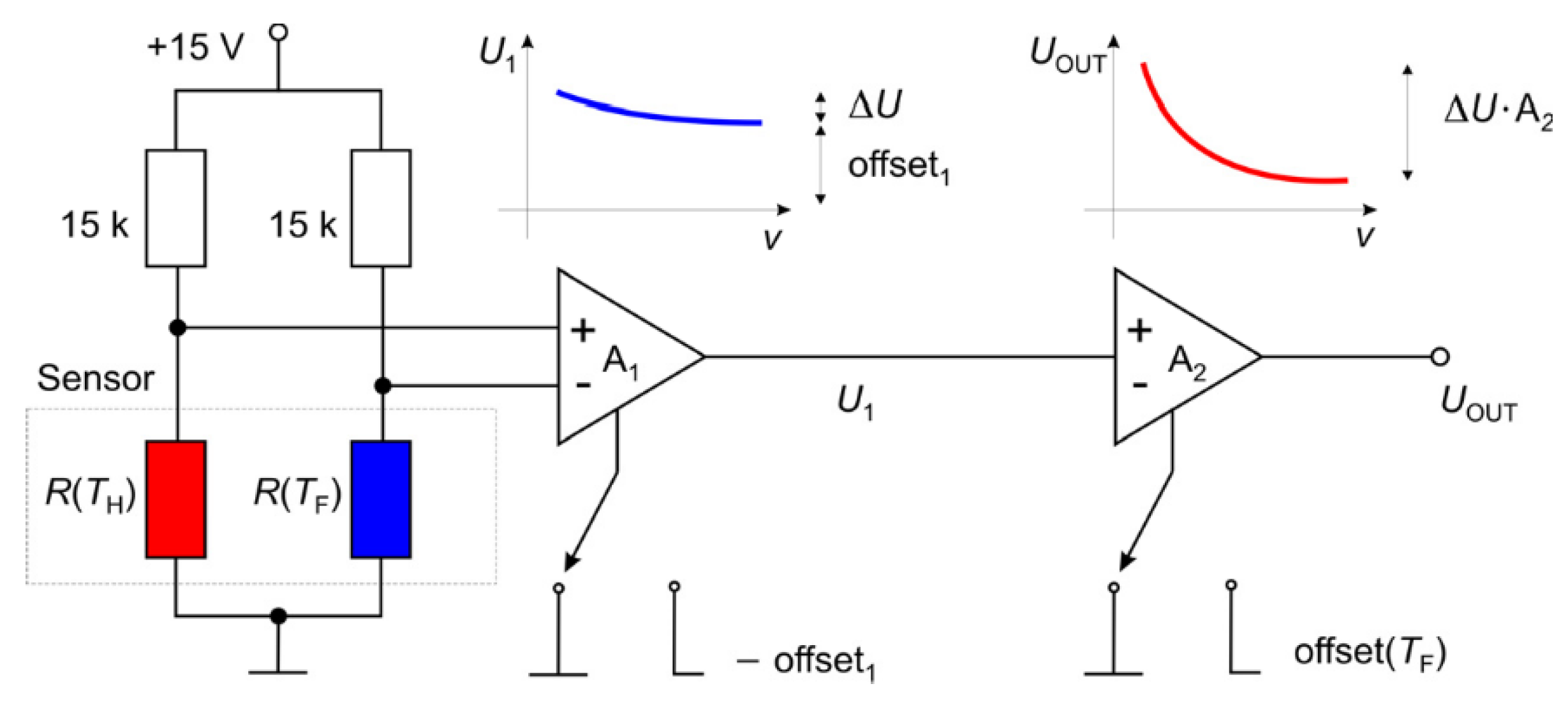
Figure 2b (i.e., the signal variation over the desired measurement range) lies in a range of only 1 K indicating that a high amplification and subsequent thorough signal conditioning must be applied. The signal conditioning circuit used for this purpose is depicted in
Figure 3. It consists of a Wheatstone bridge and two amplifiers with optional offset correction. The electrical current through the Pt100 elements amounts to approximately 1 mA ensuring that self heating effects are minimized. When the offset correction of the first instrumentation amplifier is turned off, its output signal
U1 correlates to the heater excess temperature depicted in
Figure 2b. For proper signal conditioning, the offset (denoted as offset1 in
Figure 3) must be removed. The offset corrected signal is then normalized to the desired output range by the second amplifier in order to obtain the best readout and sensitivity.
Typically, the output signal
UOUT depends on the fluid temperature
TF. The exact temperature dependence is a function of many factors such as fluid parameters, pipe and heater material, or overall amplification (A
1∙A
2) and must be determined experimentally. It can be accounted for, by measuring the fluid temperature and applying an appropriate offset at the second amplifier (denoted as offset (
TF) in
Figure 3). Preliminary evaluation using the sensor prototype (water as a fluid, copper pipe and heater, A
1 = 1000, A
2 = 7.5, offset
1 ≈ 4.4 V, heater supplied by a constant current, heating power approximately 7 W) reveals a temperature coefficient in the range of a few percent per 1 K fluid temperature change. Thus, a signal correction must be applied in most applications.
5. Results
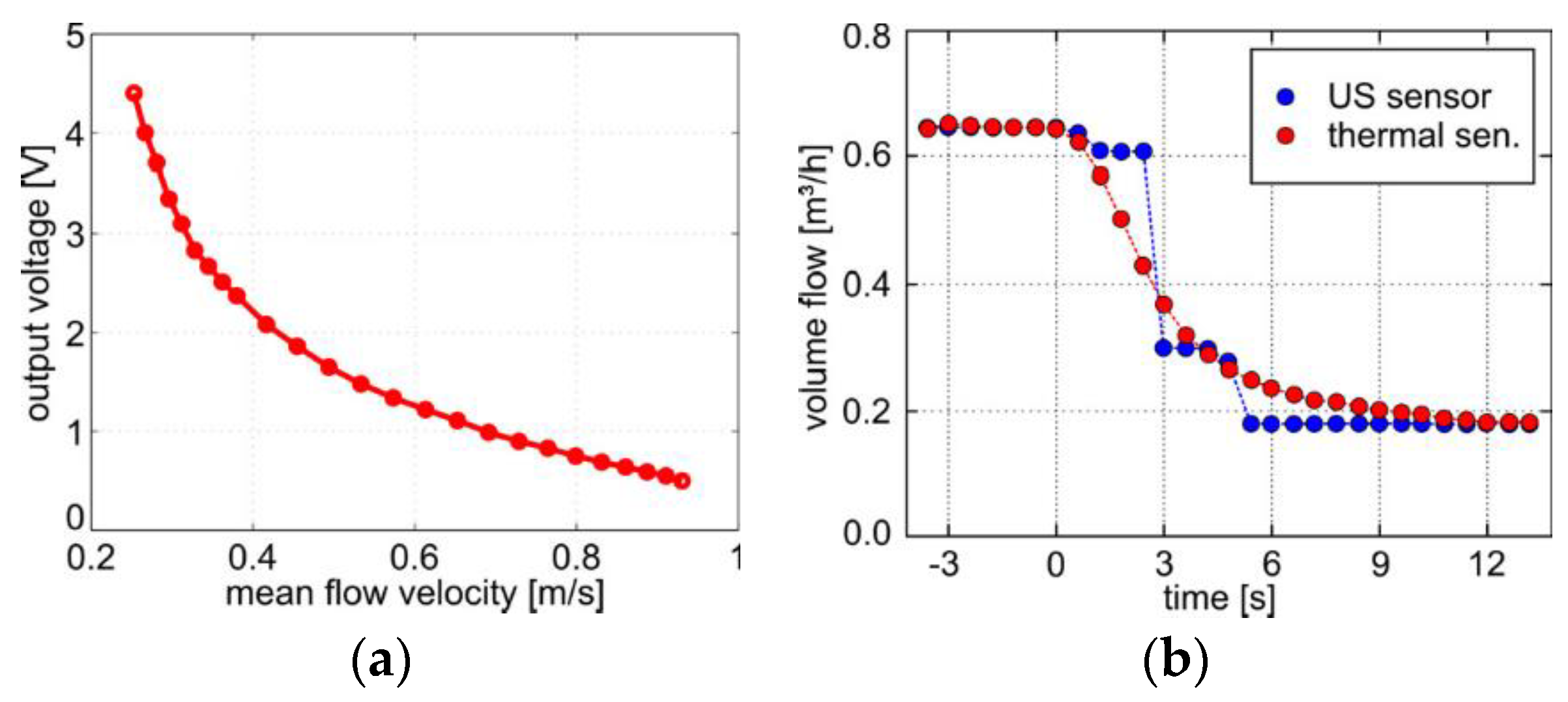
The sensor prototype was tested in a hydraulic system using water as test fluid. The deployed water pump allows for mean flow velocities in the sensor pipe up to 1 m/s. The overall amplification and the offset were chosen such that the sensor output signal fits between 0 V and 5 V in the flow range of interest (between 0.2 m/s and 1 m/s). Hence, the output can easily be sampled with any commercially available microcontroller.
The obtained conversion characteristic is depicted in
Figure 4a. Applying the inverse function of the conversion characteristic from
Figure 4a, the mean flow velocity inside the pipe can be calculated. The highest sensitivity is reached in the lower velocity range. For high flow velocities, the signal saturates and the sensitivity decreases.
In order to estimate the order of magnitude of the time constant, sudden changes of the volume flow were induced by fast adjusting (approx. 1 s) of a pressure reduction valve.
Figure 4b shows a comparison of the sensor response for a typical clamp-on US sensor and the presented low-cost, non-invasive thermal flow sensor. Our prototype of the thermal flow sensor shows good accuracy but slower response time.
6. Conclusions
We presented a feasibility study on non-invasive flow rate measurements in metal pipes utilizing a thermal flow sensor. The proposed thermal flow transduction comprises two temperature sensors and a heater, all mounted on the outer pipe surface. The temperature difference of the Pt100 elements (i.e., the heater excess temperature) depends on the fluid velocity. However, a thorough signal conditioning must be applied to derive the mean volume flow inside the pipe.
The investigated sensor prototype consists of two miniaturized Pt100 elements with a copper wire wound around them. One coil was operated as a heater, whereas another one just serves as a “dummy” reducing the transient time. Practical realizations should comprise self adhesive Pt100 elements and heating stripes, which can be easily mounted on the pipe surface.
First measurement results demonstrate the feasibility of non-invasive measurements on metal pipes in hydraulic circuits by means of low-cost thermal flow transduction instead of high-priced clamp-on ultrasonic sensors. The sensor prototype was tested in a measurement range between 0.2 m/s and 1 m/s. By appropriately adjusting the sensor electronics lower or higher flow range can also be achieved. The general drawback, however, is the saturation of the output characteristic with increasing flow velocity. Moreover, the output signal is temperature-dependent, so the variations of the fluid temperature during the measurements must be taken into account.
In comparison with a typical commercially available clamp-on US sensor, the presented non-invasive, low-cost thermal sensors features an extremely simple design and good accuracy, however, at the cost of a slower response time.


