MOEMS Based Single Chip Lorentz Force Magnetic Gradiometer †
by
 ,
,
Matthias Kahr
1,* ,
,
Michael Stifter
1,
Harald Steiner
1,
Wilfried Hortschitz
1,
Gabor Kovacs
1,
Andreas Kainz
2,
Johannes Schalko
2 and
Franz Keplinger
2 1
Department for Integrated Sensor Systems, Danube University Krems, 2700 Wiener Neustadt, Austria
2
Institute of Sensor and Actuator Systems, TU Wien, 1040 Vienna, Austria
*
Author to whom correspondence should be addressed.
†
Presented at the Eurosensors 2018 Conference, Graz, Austria, 9–12 September 2018.
Proceedings 2018, 2(13), 724; https://doi.org/10.3390/proceedings2130724
Published: 21 December 2018
(This article belongs to the Proceedings of EUROSENSORS 2018)
Abstract
:The functional principle of an optical gradient magnetic field sensor consisting of two independent laterally oscillating masses on a single chip is reported. These oscillations are caused by the Lorentz forces resulting from an alternating current through the masses interacting with a static magnetic field. Light is modulated by relative in-plane movement of the masses and a fixed frame and subsequently detected by two photodiodes. Evaluation of magnitude and phase of the output signal reveals information about the uniformity of the magnetic field. The sensor is capable of detecting uniaxially strength and direction of magnetic gradient fields, offset gradient fields and homogeneous fields.
1. Introduction
The application range of gradient field sensors comprises varies areas ranging from the maritime sector [1], measurements of magnetic properties in mining, magnetic geology [2] up to magnetic dipole characterisation [3] and many more. Gradiometers based on resonating micromachined structures combine the advantages of magnitude amplification due to resonant operation principle and large dynamic measurement range. The presented MOEMS (micro-opto-electromechanical systems) gradiometer is based on the modulation of a perpendicularly introduced light flux through a static and deflectable gratings and consists of an optical readout which decouples the sensing part from the electronic components [4,5]. The optical readout has proven to be highly sensitive [6].
2. Sensing Principle
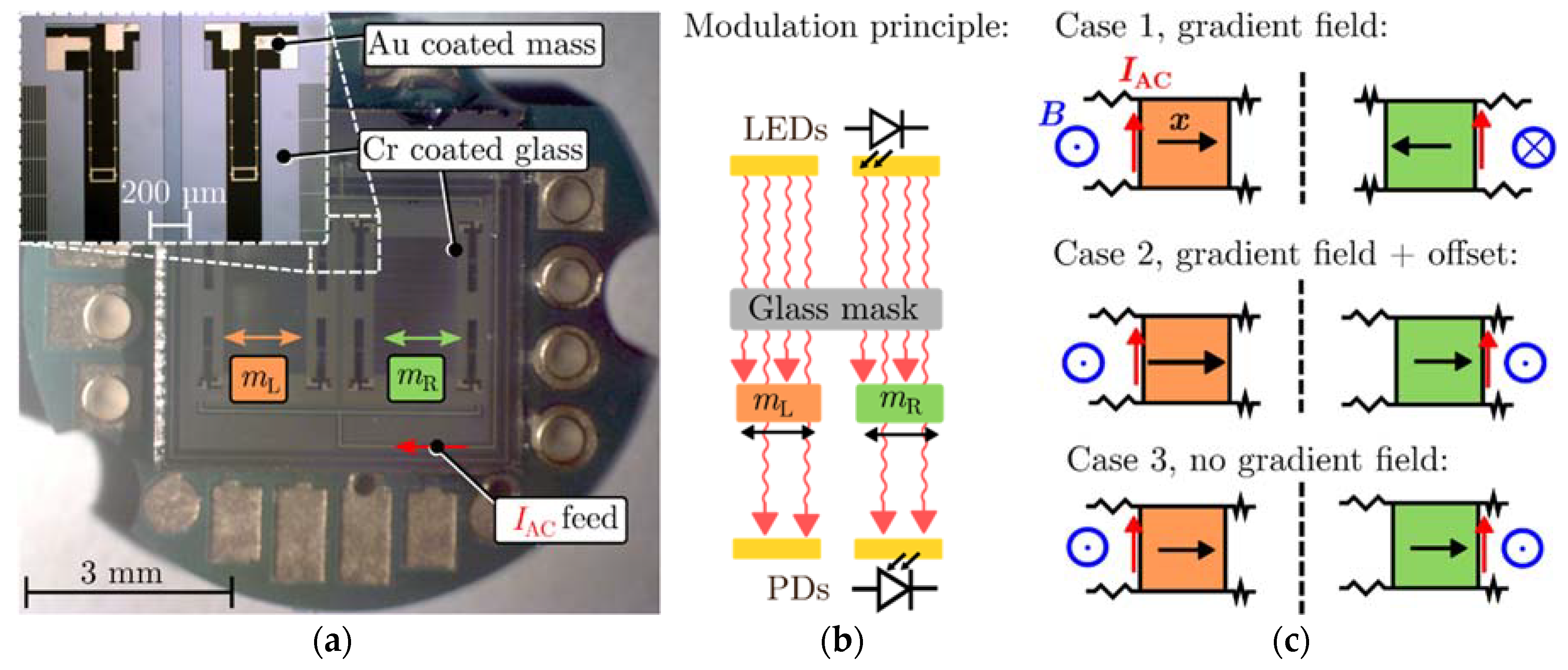
A silicon MEMS device was designed consisting of two independent, laterally oscillating masses structured with optical gratings (Figure 1a). Gold conductor paths via the outmost springs and alongside the edge of the masses (sensing areas) enable Lorentz force excitation. The Si device is bonded onto a glass carrier consisting of corresponding static gratings made of evaporated chromium. Two photodiodes (one below each mass) receive modulated light flux by relative in-plane movement from the stencil masses and fixed glass mask (Figure 1b). Both masses are designed identical but differ with respect to the alignment of the gratings. On condition that the structures deflect in the same direction, one mass will open the apertures whereas the other mass will close them, resulting in a 180◦ phase difference ϕmL and ϕmR detected by the photodiodes. As long as the masses deflect in opposite directions, the apertures either close or open simultaneously, thus no phase difference is measured. This distinction in phase information gives primary feedback if a homogeneous or gradient magnetic field, respectively is present (1c)). Finally, combined information of the output signal’s magnitude and phase enables proper distinction between magnetic gradient fields (Case 1), offset gradient fields (Case 2) and homogeneous fields (Case 3).
3. Measurement Set-Up
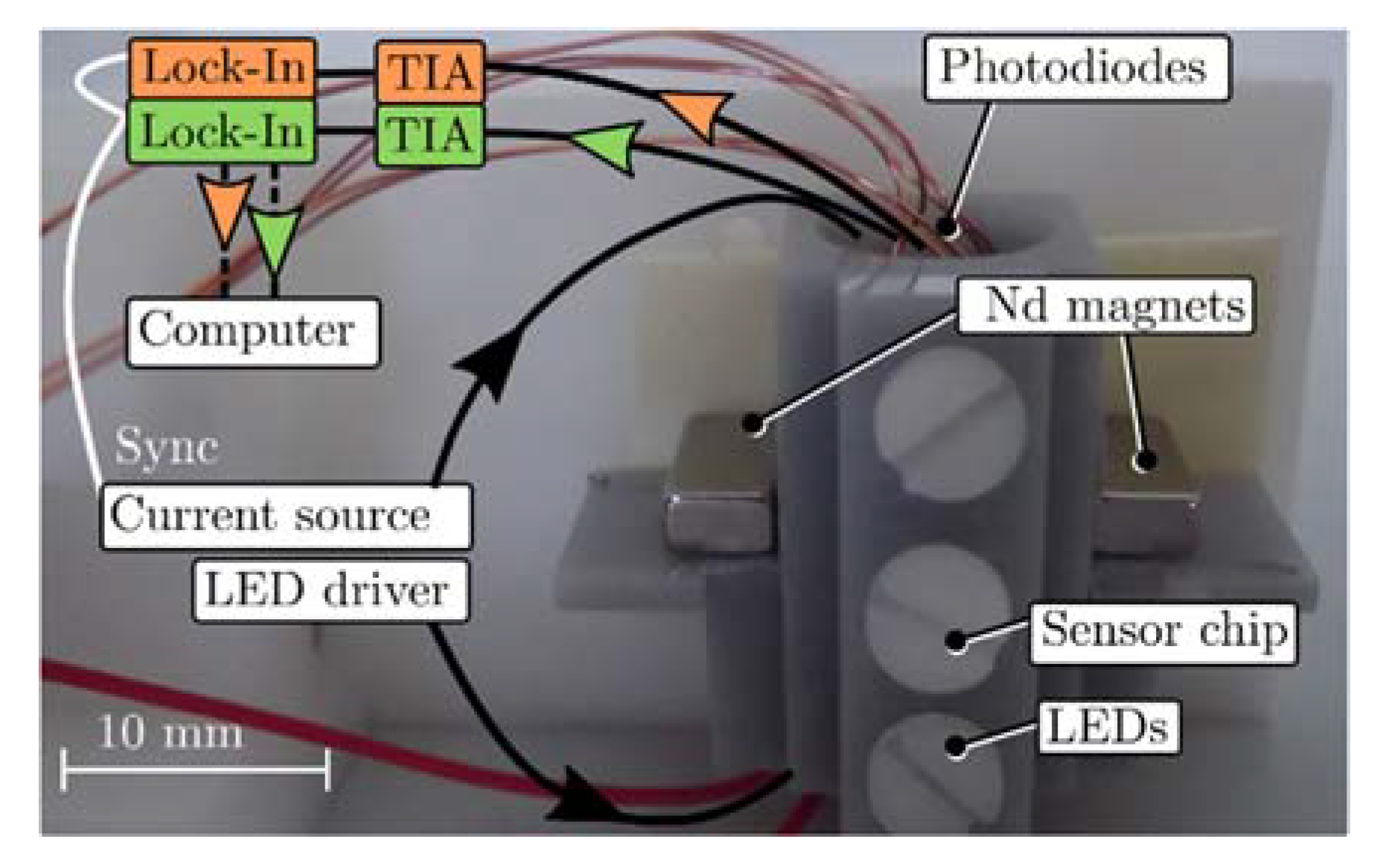
The sensor was examined in three different magnetic field configurations realised with neodymium magnets. Figure 2 depicts a mounting unit to fix LEDs, sensor, photodiodes and ledges for the magnets. The field distribution was determined with an axial Hall probe (Teslameter FM302, AS-HAP) prior serving as a reference for the sensor. A Keithley current source model 6221 provided an AC current over both masses and, hence, induced in-plane deflection in presence of a magnetic field. The modulated light was detected individually by photodiodes, the signal amplified and converted into a voltage with a transimpedance amplifier (TIA, OPA404) and acquired with lock-in amplifiers (SR830, SR865).
4. Results
The occurring B-field distribution created by the magnets for gradient fields (Case 1), offset gradient fields (Case 2) and homogeneous fields (Case 3) is shown in the insets of Figure 3a,c,e, respectively. The magnetic field detected by the sensor is evaluated with the known position of the sensor within the field and beyond with the known distance of the masses’ sensing area.
A pure gradient field of 10 mT/mm was measured and affirmed with the coefficient of determination R2 of 98.8% (Case 1). The corresponding measured transfer function is depicted in Figure 3b. Opposite oscillation of the masses denotes an opposite magnetic field direction, hence the difference of the phase is zero and indicates a gradient field.
The offset gradient field accomplished with a single magnet was determined to be −5.29 mT/mm (Case 2). Here, the masses oscillate in the same direction with a phase difference of 180° which denotes a unidirectional B-field. Henceforth, a difference of the masses’ magnitude solely indicates a magnetic gradient field (Figure 3d).
The sensing areas ideally detect the same magnetic field by symmetric placement of the identical magnets. Nevertheless, due to placement errors of the Si chip onto the PCB board, 3D-printing tolerances and possible differences from the magnet fabrication, a small gradient field of −0.04 mT/mm was measured (Case 3). This almost homogeneous field induces a phase difference of 180° and equal magnitude deflection of both Lorentz force excited masses (Figure 3f).
5. Conclusions
The functionality of a single chip Lorentz force magnetic gradiometer with optical readout based on the modulation of light flux was shown. Three different field configuration were applied and the sensor’s transfer function recorded for magnetic gradient fields, offset gradient fields and homogeneous fields. The simplified local evaluation of the field gradient due to the known distance of the masses’ sensing area is promising for an accurate characterisation of magnetic field distribution.
Acknowledgments
This work was supported by the country of Lower Austria, the Austrian Science Fund (FWF, project P 28404-NBL) and the prototype funding program PRIZE (project P1621687) of the Austria Wirtschaftsservice Gesellschaft mbH (aws).
Conflicts of Interest
The authors declare no conflict of interest.
References
- Salem, A.; Hamada, T.; Asahina, J.K.; Ushijima, K. Detection of unexploded ordnance (UXO) using marine magnetic gradiometer data. Explor. Geophys. 2005, 36, 97–103. [Google Scholar] [CrossRef]
- Lucas, I.; Michelena, M.D.; del Real, R.P.; de Manuel, V.; Plaza, J.A.; Duch, M.; Esteve, J.; Guerrero, H. A New Single-Sensor Magnetic Field Gradiometer. Sens. Lett. 2009, 7, 563–570. [Google Scholar] [CrossRef]
- Stifter, M.; Steiner, H.; Hortschitz, W.; Sauter, T.; Glatzl, T.; Dabsch, A.; Keplinger, F. MEMS micro-wire magnetic field detection method at CERN. IEEE Sens. 2015, 7, 1–4. [Google Scholar] [CrossRef]
- Hortschitz, W.; Steiner, H.; Stifter, M.; Kainz, A.; Kohl, F.; Siedler, C.; Schalko, J.; Keplinger, F. Novel MOEMS Lorentz Force Transducer for Magnetic Fields. Procedia Eng. 2016, 168, 680–683. [Google Scholar] [CrossRef]
- Hortschitz, W.; Steiner, H.; Sachse, M.; Stifter, M.; Kohl, F.; Schalko, J.; Jachimowicz, A.; Keplinger, F.; Sauter, T. Robust Precision Position Detection with an Optical MEMS Hybrid Device. IEEE Trans. Ind. Electron. 2012, 59, 4855–4862. [Google Scholar] [CrossRef]
- Hortschitz, W.; Steiner, H.; Stifter, M.; Kohl, F.; Kahr, M.; Kainz, A.; Raffelsberger, T.; Keplinger, F. Novel high resolution MOEMS inclination sensor. In Proceedings of the 2014 IEEE SENSORS, Valencia, Spain, 2–5 November 2014; pp. 1893–1896. [Google Scholar] [CrossRef]
Figure 1.
(a) Sensor chip bonded onto a PCB board consisting of the two masses indicated as mL and mR. The detailed zoom view shows the stationary Cr coated glass mask on the top and the springs of the two movable masses at the bottom. (b) Light is modulated by relative in-plane movement of the glass mask and masses. (c) Three potential cases of mass oscillation depending on the field orientation.

Figure 2.
Measurement setup and schematic. A custom made 3D-printed mounting device provides a centered placement of the sensor chip between the neodymium (Nd) magnets. Depending on the orientation of the magnets either a gradient or a homogeneous B-field is realised. A pure gradient field is accomplished by anti-symmetric placement of the magnets, whereas a gradient field with offset occurs when a single magnet is used. Symmetric placement of the magnets generates a homogeneous field. Nylon screws ensures a distortion free magnetic field and fasten LEDs, sensor and photodiodes.

Figure 3.
(a,c,e) depicts the B-field distribution between the magnets characterised with a Hall probe (Teslameter FM302, AS-HAP) for different magnet configurations (insets) and position of the masses within these fields. The sensing position of the masses are located at the outermost edges and are highlighted orange and green for mL and mR, respectively. Measured transfer functions around the sensor’s resonant frequency for all three cases are shown in (b,d,f). The quality factor of 334 was extracted via the −3 dB bandwidth method.


Publisher’s Note: MDPI stays neutral with regard to jurisdictional claims in published maps and institutional affiliations. |
© 2018 by the authors. Licensee MDPI, Basel, Switzerland. This article is an open access article distributed under the terms and conditions of the Creative Commons Attribution (CC BY) license (https://creativecommons.org/licenses/by/4.0/).
Share and Cite
MDPI and ACS Style
Kahr, M.; Stifter, M.; Steiner, H.; Hortschitz, W.; Kovacs, G.; Kainz, A.; Schalko, J.; Keplinger, F. MOEMS Based Single Chip Lorentz Force Magnetic Gradiometer. Proceedings 2018, 2, 724. https://doi.org/10.3390/proceedings2130724
AMA Style
Kahr M, Stifter M, Steiner H, Hortschitz W, Kovacs G, Kainz A, Schalko J, Keplinger F. MOEMS Based Single Chip Lorentz Force Magnetic Gradiometer. Proceedings. 2018; 2(13):724. https://doi.org/10.3390/proceedings2130724
Chicago/Turabian StyleKahr, Matthias, Michael Stifter, Harald Steiner, Wilfried Hortschitz, Gabor Kovacs, Andreas Kainz, Johannes Schalko, and Franz Keplinger. 2018. "MOEMS Based Single Chip Lorentz Force Magnetic Gradiometer" Proceedings 2, no. 13: 724. https://doi.org/10.3390/proceedings2130724