Synthesis of Copper Nanoparticles Using Glass Microfluidic Device †


1
Department of Mechanical Engineering, Kanto Gakuin University, Yokohama 236-8501, Japan
2
HORIBA Techno Service Co., Ltd., Tokyo 101-0063, Japan
*
Author to whom correspondence should be addressed.
†
Presented at the Eurosensors 2018 Conference, Graz, Austria, 9–12 September 2018.
Proceedings 2018, 2(13), 1110; https://doi.org/10.3390/proceedings2131110
Published: 7 December 2018
(This article belongs to the Proceedings of EUROSENSORS 2018)
Abstract
:In a synthesis of gold nanoparticles on a microfluidic device by citrate reduction, a particle size control by changing a flow rate was reported. To apply this simple control method to the synthesis of other metallic materials, we propose the synthesis of copper nanoparticles (CuNPs) in ethylene glycol by the microfluidic device using ascorbic acid as both antioxidant and reducing agent. The experimental results found for the first time that the effect of the flow rate of agents on particle size of the synthesized CuNPs in the device.
1. Introduction
In an inkjet printing technology, metallic nanoparticles were utilized as a printing ink [1]. Copper nanoparticles (CuNPs) is attractive attention as the ink material with economic and performance advantages over silver. There are reports about the synthesis of CuNPs using liquidphase reduction [2]. But, since copper is easily oxidized, the synthesis in inert atmosphere and controlling of the reduction temperature are required.
The synthesis of metallic nanoparticles using the microfluidic device with microchannel are studied [3]. We reported a particle size control method in the synthesis of gold nanoparticles on the microfluidic device [4]. This method enables to synthesize monodispersed gold nanoparticles by controlling the flow rate.
By applying above size control method, it is expected that the synthesis of CuNPs in the microchannel can be controlled the particle size by changing the temperature and the flow rate, because the microchannel in the microfluidic device is sealed from the outside and thermal efficiency is high. But there has been no report on the size control method of CuNPs synthesis using microfluidic device. In this paper, we report the synthesis of CuNPs using glass microfluidic device.
2. Materials and Methods
2.1. Glass Device
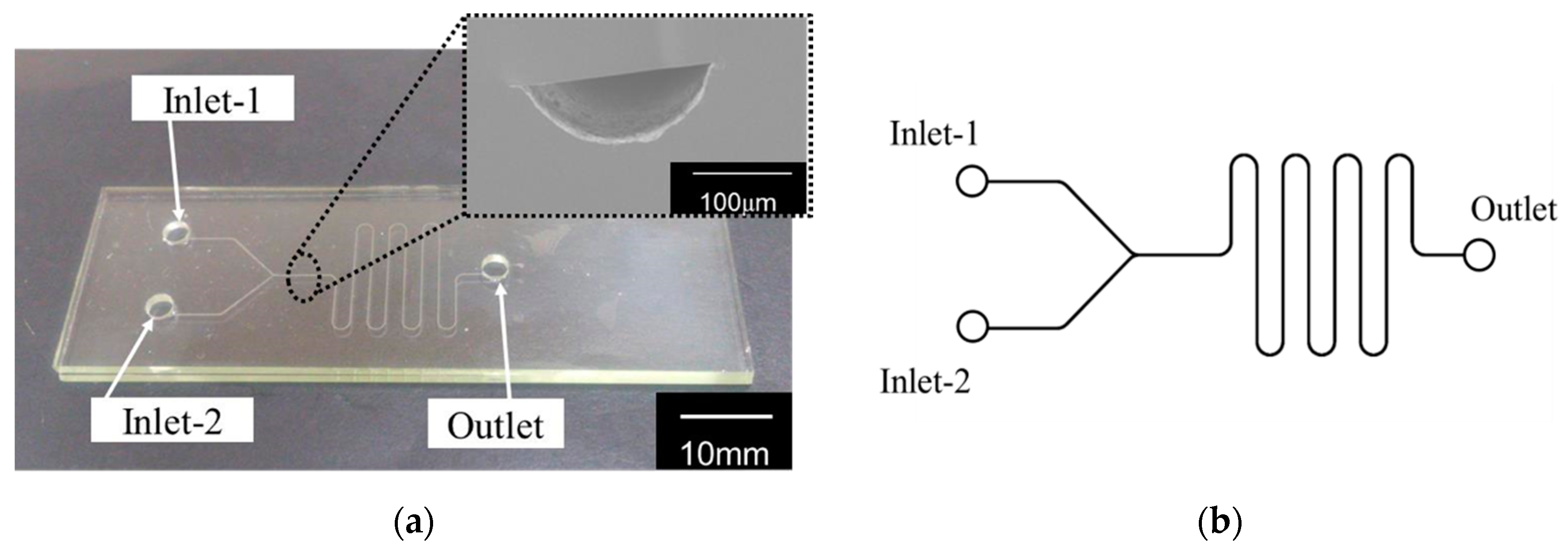
Soda-lime glass microfluidic device with a Y shaped microchannel of 260 μm width and 70 μm depth was fabricated by the micropowder blasting and thermal bonding as shown in Figure 1a [5]. A mask pattern with a Y-shaped channel (Figure 1b) was fabricated on the bottom substrate using a dry film resist (MS7050, Mitsubishi Paper Mill Ltd., Tokyo, Japan) via photolithography. Subsequently, Al2O3 microparticles with a mean diameter of 25 μm were accelerated from the nozzle with a diameter of 0.8 mm toward the sample with high-pressure (0.3 MPa) airflow and an incident angle of 90°. On the other hand, two inlet holes and one outlet hole on the upper substrate were processed by a router with a diameter of 3 mm. Finally, the two fabricated glass substrates were thermally bonded in the oven at 610 °C for 8 h and cooled at the rate of 30 °C/min under a pressure of 3.7 kPa.
2.2. Synthesis
At the flow rate of 0.001 to 0.04 mL/min, 3 mL copper (II) chloride dihydrate in ethylene glycol (solution-A, 50.1 mM), and 3 mL L-Ascorbic acid in ethylene glycol (solution-B, 505.7 mM) were simultaneously injected into Inlet-1 and Inlet-2 by syringe pump, and the synthesized CuNPs was collected from Outlet in a bottle through the silicone tube (Figure 2a). In this study, the device was set on a heater, and the temperature of device was controlled at 160 °C with a thermostat and the heat sensor (Figure 2b).
2.3. Characterization
The spectra of synthesized CuNPs were measured using a UV–visible spectrometer (UV-1240, Shimadzu Corporation, Kyoto, Japan). The synthesized CuNPs were observed using dynamic light scattering (SZ-100, Horiba Ltd., Kyoto, Japan) and transmission electron microscopy (TEM) (JEM2010, JEOL Ltd., Tokyo, Japan) to evaluate dispersibility and nanoparticle diameter.
3. Results and Discussion
3.1. Absorption Spectrum
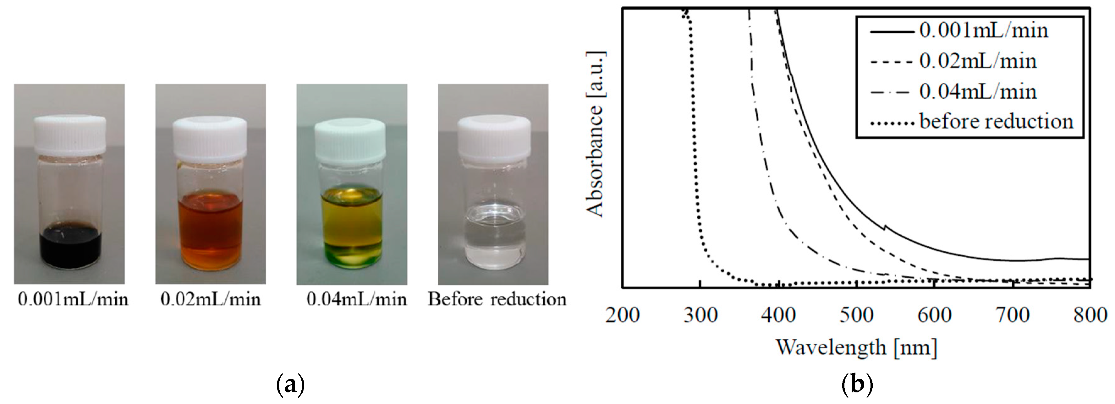
Figure 3a shows the photograph of CuNPs synthesized in the device at the temperature of 160 °C. The synthesis results confirmed that CuNPs were synthesized because the initial precursor solution before reduction changed to clear orange and dark black. Figure 3b shows UV-visible spectra of the synthesized CuNPs and precursor solution (before reduction). UV- visible spectrum was changed by increasing the flow rate [3]. But the synthesis was not completed at the flow rate of 0.001 mL/min, because of the close of the channel by the aggregation of Cu.
3.2. Dynamic Light Scattering Measurements
Figure 4 shows mean diameter and standard deviation of CuNPs synthesized in the device calculated by number-size distribution of dynamic light scattering measurement. From dynamic light scattering measurements confirmed that mean diameter and standard deviation of the synthesized CuNPs showed 1.5 nm and 0.2 nm at the flow rate of 0.04 mL/min, and the changing the flow rate was attributed to the particle size control.
3.3. TEM Images
Figure 5 shows TEM images of the synthesized CuNPs. Figure 6 shows mean diameter and standard deviation of CuNPs synthesized in the device calculated from the TEM images. We confirmed that the single sized nanoparticle was realized by the synthesis in the microfluidic device, and the particle distribution of CuNPs was changed by increasing the flow rate. Figure 6 shows mean diameter and standard deviation calculated from TEM images of CuNPs as a function of the flow rate. It was confirmed that the mean diameter and standard deviation were 3.26 nm and 1.19 nm at the flow rate of 0.04 mL/min, and the mean diameter decreased with increasing the flow rate. This decreasing tendency was good agreement with the result of dynamic light scattering measurements. The standard deviation showed maximum value at the flow rate of 0.02 mL/min.
4. Conclusions
We have demonstrated the synthesis of CuNPs using ascorbic acid as both antioxidant and reducing agent in the simple Y shaped microchannel device with controlling the temperature. The relationship of the diameter of nanoparticle and the flow rate confirmed that single size CuNPs was synthesized, and the particle size and distribution were controlled using microfluidic device.
Acknowledgments
The present study was supported in part by the Tanaka Kikinzoku Memorial Foundation.
Conflicts of Interest
The authors declare no conflict of interest. The founding sponsors had no role in the design of the study; in the collection, analyses, or interpretation of data; in the writing of the manuscript, and in the decision to publish the results.
References
- Fuller, S.B.; Wilhelm, E.J.; Jacobson, J.M. Ink-jet Printed Nanoparticle Microelectromechanical Systems. J. Microelectromech. Syst. 2002, 11, 54–60. [Google Scholar] [CrossRef]
- Li, M.; Xiang, K.; Luo, G.; Gong, D.; Shen, Q. Preparation of Monodispersed Copper Nanoparticles by an Environmentally Friendly Chemical Reduction. Chin. J. Chem. 2013, 31, 1285–1289. [Google Scholar] [CrossRef]
- Wagner, J.; Kirner, T.; Albert, J.; Köhler, J.M. Generation of Metal Nanoparticles in a Microchannel Reactor, Chem. Eng. J. 2004, 101, 251–260. [Google Scholar]
- Yagyu, H.; Yu. Tanabe, Y.; Takano, S.; Hamamoto, M. Continuous Flow Synthesis of Monodisperse Gold Nanoparticles by Liquid-phase Reduction Method on Glass Microfluidic Device. Micro Nanno Lett. 2017, 12, 536–539. [Google Scholar] [CrossRef]
- Yagyu, H.; Sugano, K.; Hayashi, S.; Tabata, O. Micropowder Blasting using Nanoparticles Dispersed Polymer Mask for Rapid Prototyping of Glass Chip. J. Micromech. Microeng. 2005, 15, 1236–1241. [Google Scholar] [CrossRef]
Figure 1.
(a) Photograph of the fabricated glass microfluidic device with the width of 260 μm and the depth of 70 μm; (b) The Y shaped microchannel pattern of the device.
Figure 1.
(a) Photograph of the fabricated glass microfluidic device with the width of 260 μm and the depth of 70 μm; (b) The Y shaped microchannel pattern of the device.

Figure 2.
(a) Schematic image of a joint section in the microchannel. The length of channel after joint section which mixing of the agents are started is 131.5 mm; (b) Experimental setup for the synthesis. Heat sensor was set to the position between inlet and outlet.
Figure 2.
(a) Schematic image of a joint section in the microchannel. The length of channel after joint section which mixing of the agents are started is 131.5 mm; (b) Experimental setup for the synthesis. Heat sensor was set to the position between inlet and outlet.

Figure 3.
(a) Photograph of the CuNPs synthesized in the device at the temperature of 160 °C; (b) UV-visible spectra of the synthesized CuNPs and precursor solution (before reduction).
Figure 3.
(a) Photograph of the CuNPs synthesized in the device at the temperature of 160 °C; (b) UV-visible spectra of the synthesized CuNPs and precursor solution (before reduction).

Figure 4.
(a) Mean diameter and (b) standard deviation of CuNPs synthesized in the device calculated by number-size distribution of dynamic light scattering measurement as a function of the flow rate.
Figure 4.
(a) Mean diameter and (b) standard deviation of CuNPs synthesized in the device calculated by number-size distribution of dynamic light scattering measurement as a function of the flow rate.

Figure 5.
TEM images of the synthesized CuNPs with the flow rate of (a) 0.0001 mL/min; (b) 0.02 mL/min; and (c) 0.04 mL/min.
Figure 5.
TEM images of the synthesized CuNPs with the flow rate of (a) 0.0001 mL/min; (b) 0.02 mL/min; and (c) 0.04 mL/min.

Figure 6.
(a) Mean diameter and (b) standard deviation calculated from TEM images of CuNPs as a function of the flow rate.
Figure 6.
(a) Mean diameter and (b) standard deviation calculated from TEM images of CuNPs as a function of the flow rate.

Publisher’s Note: MDPI stays neutral with regard to jurisdictional claims in published maps and institutional affiliations. |
© 2018 by the authors. Licensee MDPI, Basel, Switzerland. This article is an open access article distributed under the terms and conditions of the Creative Commons Attribution (CC BY) license (http://creativecommons.org/licenses/by/4.0/).
Share and Cite
MDPI and ACS Style
Liang, Y.; Shinozaki, Y.; Yagyu, H. Synthesis of Copper Nanoparticles Using Glass Microfluidic Device. Proceedings 2018, 2, 1110. https://doi.org/10.3390/proceedings2131110
AMA Style
Liang Y, Shinozaki Y, Yagyu H. Synthesis of Copper Nanoparticles Using Glass Microfluidic Device. Proceedings. 2018; 2(13):1110. https://doi.org/10.3390/proceedings2131110
Chicago/Turabian StyleLiang, Yiyang, Yoko Shinozaki, and Hiromasa Yagyu. 2018. "Synthesis of Copper Nanoparticles Using Glass Microfluidic Device" Proceedings 2, no. 13: 1110. https://doi.org/10.3390/proceedings2131110