Proceeding Paper

All Inkjet-Printed B Field Sensor †

DIEEI University of Catania, v.le A. Doria, 6-95125 Catania, Italy
*
Author to whom correspondence should be addressed.
Presented at the Eurosensors 2017 Conference, Paris, France, 3–6 September 2017.
Proceedings 2017, 1(4), 621; https://doi.org/10.3390/proceedings1040621
Published: 17 August 2017
(This article belongs to the Proceedings of Proceedings of Eurosensors 2017, Paris, France, 3–6 September 2017)

Abstract

:
This paper presents the realization and the experimental characterization of a low cost inkjet-printed DC magnetic field sensor. The device consists of a thin flexible cantilever beam operated at its first resonance frequency by the interaction between the target magnetic field and an AC current flowing through a coil printed on the beam. A resistive readout strategy is implemented by a printed strain gauge to measure the beam deflection strength, which is correlated to the target field strength. A dedicated electronics is used for the sake of the sensor operation. The sensor behaviour has been investigated for different values of the driving current and the target magnetic field. As an example, the sensor responsivity and resolution for a driving current of 20 mA @ 9.1 Hz (the beam resonance frequency) are 0.009 Ω/Ω/T and 1.2 mT, respectively.

1. Introduction

Nowdays magnetic field sensors with high performances are required in different applications including position sensing, speed detection, current detection, non-contact switching, space exploration, vehicle detection, electronic compasses, geophysical prospecting, non-distructive testing, brain function mapping [1].
The development of very cheap magnetic field sensors fosters their use in harsh application contexts requiring disposable device, which are enabled by inkjet printing technology [2].
Of course, towards printed magnetic field sensors, an example of low cost approach is represented by the printed circuit board (PCB) technology for the realization of fluxgate sensors [3,4,5]. The main drawback of these technology is the need for masks and long time production, which does not enable rapid prototyping of lab-scale prototypes.
Compared to standard approaches, printing technologies represent low cost solutions to address a wide set of applications requiring cheap and disposable devices [6]. Main techniques for the realization of flexible printed sensors are screen printing and inkjet printing. Screen printing is based on deposition on a substrate of thick film of material by the use of masks and a roller pressure mechanism. Many different materials, like conductive, insulating and other functional layers, are available to be deposited on the surface of the substrate and many different typologies of sensors realized by screen printing are available in [7,8,9].
Main drawbacks of screen printing are related to the use of masks and waste of materials. Conversely, inkjet printing is a contactless technique which allows for the real rapid prototyping of electronic component with particular regards to sensors. Interesting advantages of inkjet technologies reside in the direct printing feature, high spatial resolution and compatibility with many substrates. Among materials compatible with inkjet printing technology polymers like PEDOT-PSS (3,4-ethylen dioxythiophene) and PANI (Polyaniline) and conductive silver nanoparticles are widely used.
The possibility to print both conductors and functional layers by low cost printers is a great advancement in terms of effective solutions for the rapid prototyping of sensors. Example of sensors developed by low cost inkjet printers are available in [10,11,12,13,14,15,16].
This paper focuses on the development of an inkjet-printed magnetic field sensor. The device consists of a thin flexible beam clamped on one end, where a dedicated actuation and sensing features have been realized by inkjet printing. The working principle of the device and the experimental results are discussed in the following sections.

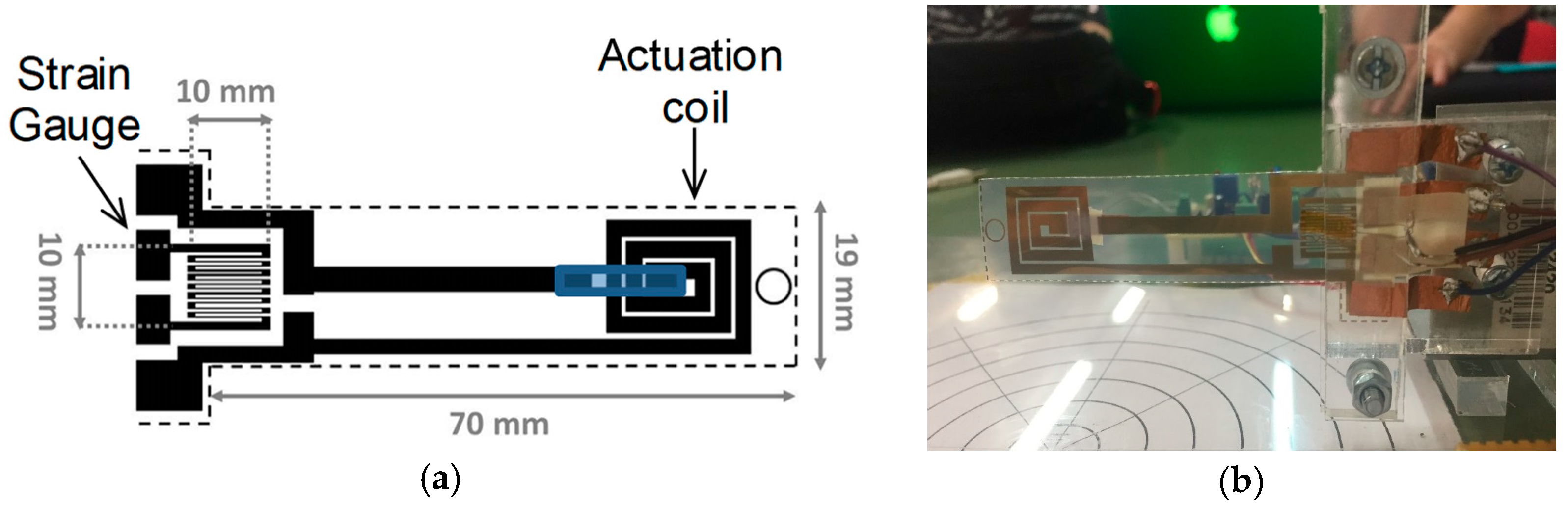
2. An Overview of the System Developed

The layout of the developed inkjet-printed sensor is shown in Figure 1a. The device consists of a thin flexible cantilever beam operated at its first resonance frequency by the interaction between the target magnetic field and an AC current flowing through a coil printed on the beam. The flexible substrate is made of PET (polyethylene terephthalate) with a thickness of 140 µm. A resistive readout strategy is implemented by a printed strain gauge to measure the beam deflection strength, which is correlated to the target field strength. Physical and electrical characteristics of the sensor are given in Table 1.
The interaction between the target magnetic field to be measured and the current flowing into the printed coil will produce a beam deflection. The latter is measured through the printed strain gauge which implements the resistive readout strategy. In order to implement the above sensing mechanism, the inductive coil is electrical driven at the mechanical resonance frequency of the beam.
The printed coil is square-shaped with 3 windings and the outer side of 16.5 mm; the spacing and the track width are 0.5 mm and 2 mm, respectively. The measured value of the inductance of the printed coil, LS, is 84.6 nH.
The strain sensor has been designed with the aim of capturing the main curvature area of the beam. In particular, the printed strain gauge is 10 mm long and 10 mm wide, while the spacing and the track width are 300 µm. Above dimensions have been fixed by fulfilling constraints given by the beam dimensions and wiring needs as shown in Figure 1b. The resistance of the printed strain gauge, RS, is 123.5 Ω, while its Gauge Factor is 1.9.
The printing process adopted to realize both the strain gauge and the coil on the PET substrate uses a low cost inkjet printer and a metal ink for the realization of conductive patterns.
A voltage-to-current converter has been developed to drive the conductive printed coil. A dedicated Wheatstone bridge has been used for the sake of signal conditioning. To compensate for the effect of the temperature fluctuations, a dummy gauge has been included.

3. Experimental Results

Experiments have been performed in order to estimate the natural frequency of the beam, the SG response and finally the behaviour of the B Field sensor as a function of the driving current.

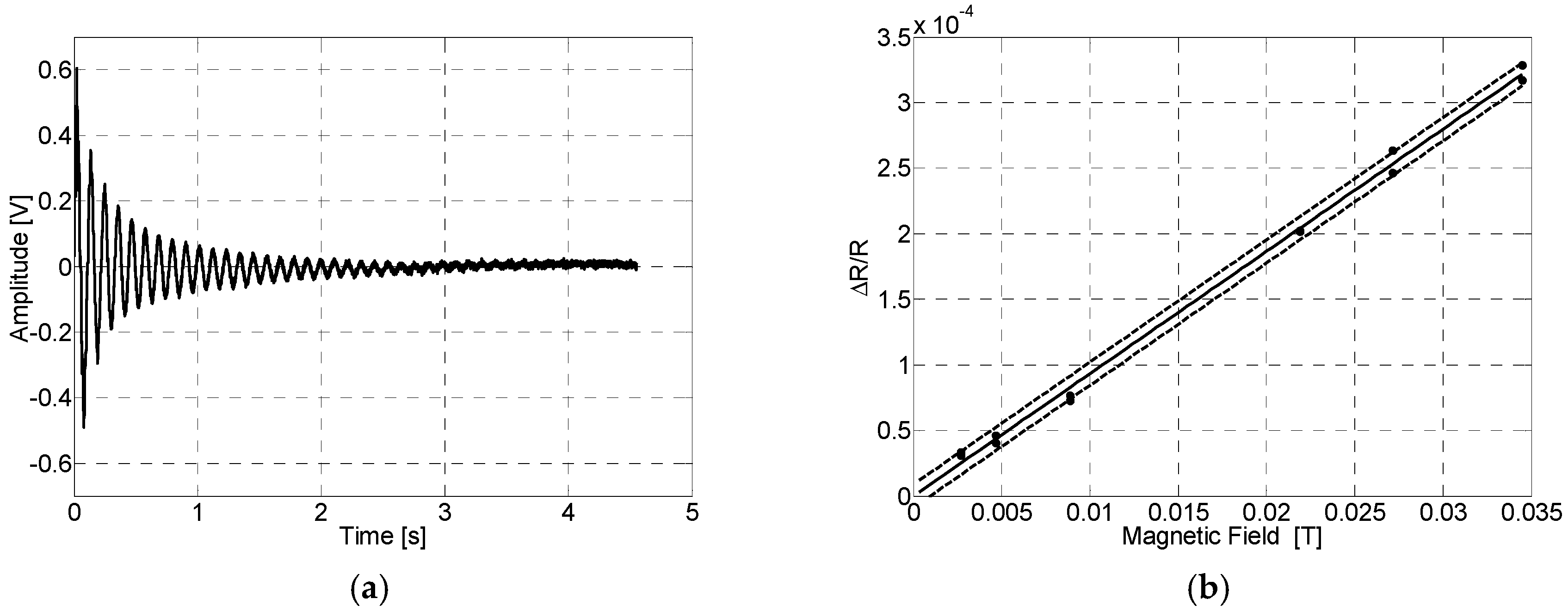
3.1. Assessment of the Beam Natural Frequency and the Printed Strain Gauge

The first experiment was aimed to assess the impulse response of the beam structure. The Figure 2a shows the impulse response of the beam, stimulated by a pulsed current, which leads to the estimation of the natural frequency of 9.1 Hz. The impulse response was also used to estimate the Gauge Factor of 1.9 of the printed strain sensor. To such aim a reference strain sensor, bonded on the opposite side of the beam, was used.

3.2. The IJP-BField Sensor Response

The last experiment is aimed to estimate the sensor response, in terms of ΔRS/RS, for different values of the target magnetic field and the driving current. A characterization survey was performed to assess the sensor behaviour in the range [0–34.4] mT, for a driving current ranging in [20–90] mA @ 9.1 Hz. The upper current value has been fixed to cope with constraints of the inkjet printed patterns. The external target field is generated by the neodymium magnets. To change the intensity of the magnetic field, the permanent magnets have been placed at several distances, d, from the center of the printed coil. The reference magnetic field sensor SS496A1 by Honeywell has been used to achieve an independent measurement of the target magnetic field. The device responsivity and resolution for different values of the driving current are given in Table 2.

4. Conclusions

Although the performances of the developed device are in line with low cost Commercial Off-The-Shelf (COTS) sensors, main outcomes of the proposed approach come from the sensor architecture and the low cost direct printing technology adopted. The inkjet printed cantilever beam, which is the low cost part of the system, can be easily replaced thus providing dramatic advantages for operation in harsh environments. Further efforts will be dedicated to develop a model of the presented device, as well as to better investigate the sensor performances.

Conflicts of Interest

The authors declare no conflict of interest.

References

  1. Todaro, M.T.; Sileo, L.; De Vittorio, M. Magnetic Field Sensors Based on Microelectromechanical Systems (MEMS) Technology. In Magnetic Sensors—Principles and Applications; Kuang, K., Ed.; InTech: Rijeka, Croatia, 2012; ISBN 978-953-51-0232-8. [Google Scholar]
  2. Andò, B.; Baglio, S. Inkjet-Printed Sensors: A Useful Approach for Low Cost, Rapid Prototyping. IEEE Instrum. Meas. Mag. 2011, 14, 36–40. [Google Scholar] [CrossRef]
  3. Kubik, J.; Pavel, L.; Ripka, P. PCB racetrack fluxgate sensor with improved temperature stability. Sens. Actuators A Phys. 2006, 130–131, 184–188. [Google Scholar] [CrossRef]
  4. Baschirotto, A.; Dallago, E.; Malcovati, P.; Marchesi, M.; Venchi, G. Development and Comparative Analysis of Fluxgate Magnetic Sensor Structures in PCB Technology. IEEE Trans. Magn. 2006, 42, 1670–1680. [Google Scholar] [CrossRef]
  5. Kubík, J.; Pavel, L.; Ripka, P.; Kašpar, P. Low-Power Printed Circuit Board Fluxgate Sensor. IEEE Sens. J. 2007, 7, 179–183. [Google Scholar] [CrossRef]
  6. Mäntysalo, M.; Pekkanen, V.; Kaija, K.; Niittynen, J.; Koskinen, S.; Halonen, E.; Mansikkamaki, P.; Hameenoja, O. Capability of Inkjet Technology in Electronics Manufacturing. In Proceedings of the Electronic Components and Technology Conference, San Diego, CA, USA, 26–29 May 2009; pp. 1330–1336. [Google Scholar]
  7. Unander, T.; Nilsson, H.E. Characterization of printed moisture sensors in packaging surveillance applications. IEEE Sens. J. 2009, 9, 922–928. [Google Scholar] [CrossRef]
  8. Lakhmi, R.; Debeda, H.; Dufour, I.; Lucat, C. Force sensors based on screen-printed cantilevers. IEEE Sens. J. 2010, 10, 1133–1137. [Google Scholar] [CrossRef]
  9. Jacq, C.; Lüthi, B.; Maeder, T.; Lambercy, O.; Gassert, R.; Ryser, P. Thick-film multi-DOF force/torque sensor for wrist rehabilitation. Sens. Actuators A Phys. 2010, 162, 361–366. [Google Scholar] [CrossRef]
  10. Crowley, K.; Morrin, A.; Hernandez, A.; O’Malley, E.; Whitten, P.G.; Wallace, G.; Smyth, M.R.; Killard, A.J. Fabrication of an ammonia gas sensor using inkjet-printed polyaniline nanoparticles. Int. J. Pure Appl. Anal. Chem. 2008, 77, 710–717. [Google Scholar] [CrossRef]
  11. Andersson, H.; Manuilskiy, A.; Unander, T.; Lidenmark, C.; Forsberg, S.; Nilsson, H.-E. Inkjet printed silver nanoparticle humidity sensor with memory effect on paper. IEEE Sens. J. 2012, 12, 1901–1905. [Google Scholar] [CrossRef]
  12. Andò, B.; Baglio, S. All-Inkjet Printed Strain Sensors. IEEE Sens. J. 2013, 13, 4874–4879. [Google Scholar] [CrossRef]
  13. Lorwongtragool, P.; Sowade, E.; Watthanawisuth, N.; Baumann, R.R.; Kerdcharoen, T. A Novel Wearable Electronic Nose for Healthcare Based on Flexible Printed Chemical Sensor Array. Sensors 2014, 14, 19700–19712. [Google Scholar] [CrossRef] [PubMed]
  14. Andò, B.; Baglio, S.; Marletta, V.; Pistorio, A. A Contactless InkJet Printed Passive Touch Sensor. In Proceedings of the International Instrumentation and Measurement Technology Conference (I2MTC), Montevideo, Uruguay, 12–15 May 2014. [Google Scholar]
  15. Andò, B.; Baglio, S.; Lombardo, C.O.; Marletta, V.; Pistorio, A. A Low-Cost Accelerometer Developed by Inkjet Printing Technology. IEEE Trans. Instrum. Meas. 2015, 65, 1242–1248. [Google Scholar] [CrossRef]
  16. Andò, B.; Baglio, S.; Pasqualeb, G.D.; Pollicino, A.; D’Agata, S.; Gugliuzzo, C.; Lombardo, C.; Re, G. An Inkjet Printed CO2 Gas Sensor. In Proceedings of the XXIX Eurosensors, Freiburg, Germany, 6–9 September 2015. [Google Scholar]
Figure 1. (a) Layout of the inkjet-printed sensor; (b) Clamping system for wiring the printed sensor.
Proceedings 01 00621 g001
Figure 2. (a) Impulse response of the beam; (b) Sensor response (driving current of 20 mA @ 9.1 Hz).
Proceedings 01 00621 g002
Table 1. Sensor characteristics.
Sensor Physical and Electrical Characteristics
Beam SubstrateNovele™ IJ-220
Total Length70 mm
Width19 mm
Substrate Thickness140 μm
Silver Ink Thickness200 nm
Coil Resistance25.6 Ω
Coil Inductance84.6 nH
Coil Track Spacing and Width0.5 mm, 2.0 mm
Strain Gauge Resistance, RS123.5 Ω
Gauge Factor1.9
Coil Track Spacing and Width300 μm, 300 μm
Table 2. Device responsivity and resolution for different values of the driving current.
Driving Current [mA] @ 9.1 HzResponsivity [(Ω/Ω)/T]Resolution [mT/(Ω/Ω)]
200.0091.20
300.0110.46
500.0170.40
900.0240.37
Publisher’s Note: MDPI stays neutral with regard to jurisdictional claims in published maps and institutional affiliations.

