Improving the Durability of Screen Printed Conductors on Woven Fabrics for E-Textile Applications †


Department of Electronics and Computer Science, University of Southampton, Southampton SO17 1BJ, UK
*
Author to whom correspondence should be addressed.
†
Presented at the Eurosensors 2017 Conference, Paris, France, 3–6 September 2017.
Proceedings 2017, 1(4), 613; https://doi.org/10.3390/proceedings1040613
Published: 16 August 2017
(This article belongs to the Proceedings of Proceedings of Eurosensors 2017, Paris, France, 3–6 September 2017)
Abstract
:This paper reports the experimental investigation of the durability of screen printed conductor-based strain gauges on four fabrics of different stiffness by examining the change in the electrical resistances during and after bending. Emphasis is placed on improving the durability of the gauges for both positive and negative bending e-textile applications. The electrical resistance of the printed gauges is generally shown to degrade faster from positive bending than from negative bending. Compressive strain affects the behaviour of the gauges during bending but gauges perform best when they are close to the neutral axis of the printed fabric.
1. Introduction
Screen printable conductors are well suited to e-textile applications because the textile industry is familiar with the screen printing fabrication process, a straightforward method for patterning a network of shapes or designs such as electric circuits, on fabrics. However, these conductors are not durable when subjected to stresses such as bending and washing. Although their performance improves with increased encapsulation [1,2,3], recent literature show that by positioning them on the neutral axis (NA) of a screen printed e-textile, the conductors experience zero stress and their durability is greatly enhanced [3,4]. In [4], screen printed strain gauges in the proximity of the NA showed electrical resistance changes, ΔR of less than 0.1% during bending around a 5-mm radius rod whereas gauges located away from NA showed changes of 37%.
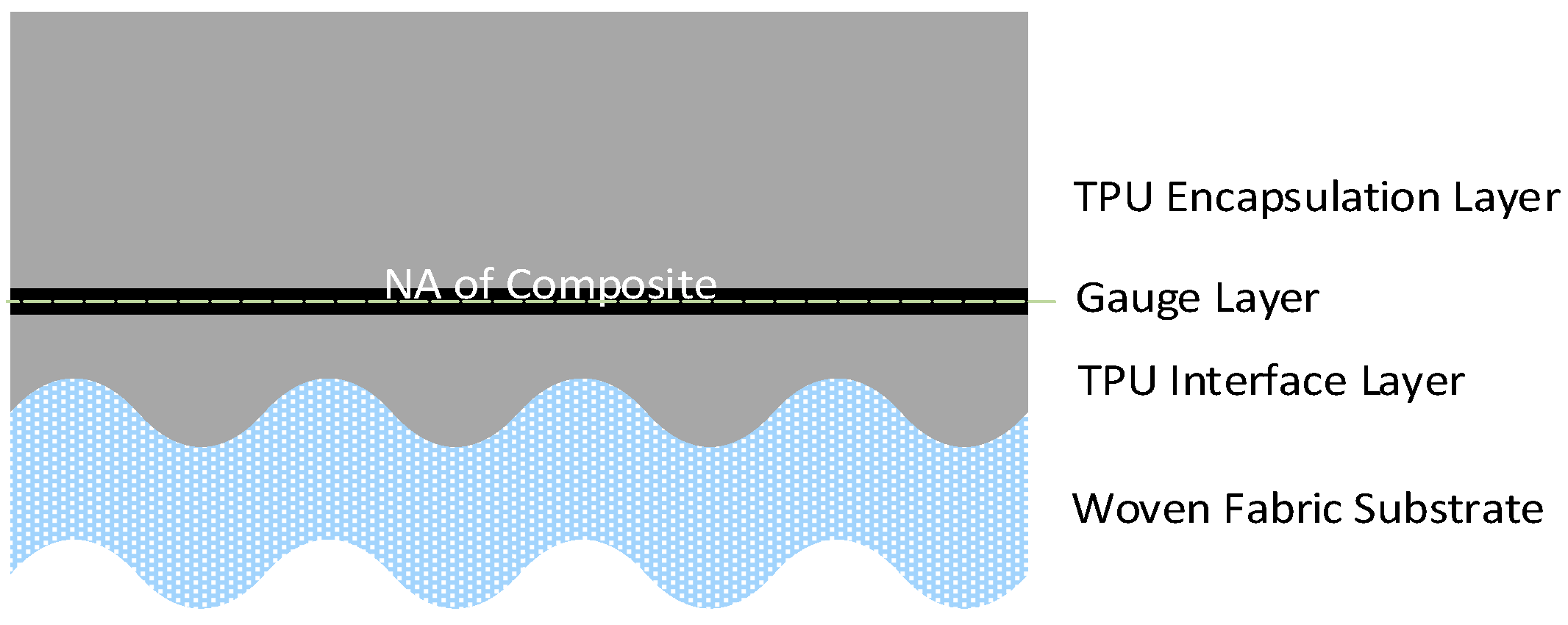
This paper investigates the effects of bending stress and fabric stiffness on the durability of the screen printed gauges during and after bending. Piezoresistive strain gauges were sandwiched between a screen printed interface and an encapsulation layer on four different fabrics. The interface layer minimises the surface roughness while the encapsulation layer protects the gauge and controls the position of the gauge within the printed fabric as shown in Figure 1. The gauges were screen printed along the warp and weft direction of fabrics with different elastic modulus in these directions so as to understand the influence of fabric stiffness on the electrical performance of the gauges. This work is useful for optimizing the position and performance of printed circuits within textiles so as to improve the application lifetime and/or productivity of the e-textile.
2. Materials and Methods
The printed fabric assembly in Figure 1 was implemented with fabrics comprising a blend of polyester/cotton/lycra yarns as shown in Table 1. Two of the fabrics, Bari and PES, are relatively stiff fabrics that have equal tensile modulus along their warp and weft directions. The remaining Lagonda and Escalade fabrics have different tensile modulus along these directions. These are stiff along the warp direction and elastic along the weft direction due to the lycra yarns. All the fabrics were supplied by Klopmann International and they are current textiles used for garments.
The interface and encapsulation layers were realised on the fabrics using screen printable UV curable thermoplastic polyurethane ink, Fabink UV-IF-1 from Smart Fabric Inks Ltd while the gauge layer was realised using a thermally curable piezoresistive carbon ink with a gauge factor of 5 also from Smart Fabric Inks Ltd. A detailed fabrication process for the printed fabric assembly and the processing parameters for inks have been reported in [1]. The printed thicknesses for the interface, strain gauge and encapsulation layers are shown in Table 1.
The printed fabrics were evaluated by subjecting them bending around a circular rod of a radius of 5 mm as shown in Figure 2. During bending the resistance change, ΔR in the gauge can be negative or positive depending upon whether it is compressed or tensioned respectively, which depends upon the position of the neutral axis and the direction of bending. In all cases, when the gauge is on the NA, it experiences a zero stress so that ΔR = 0.
3. Result and Discussion
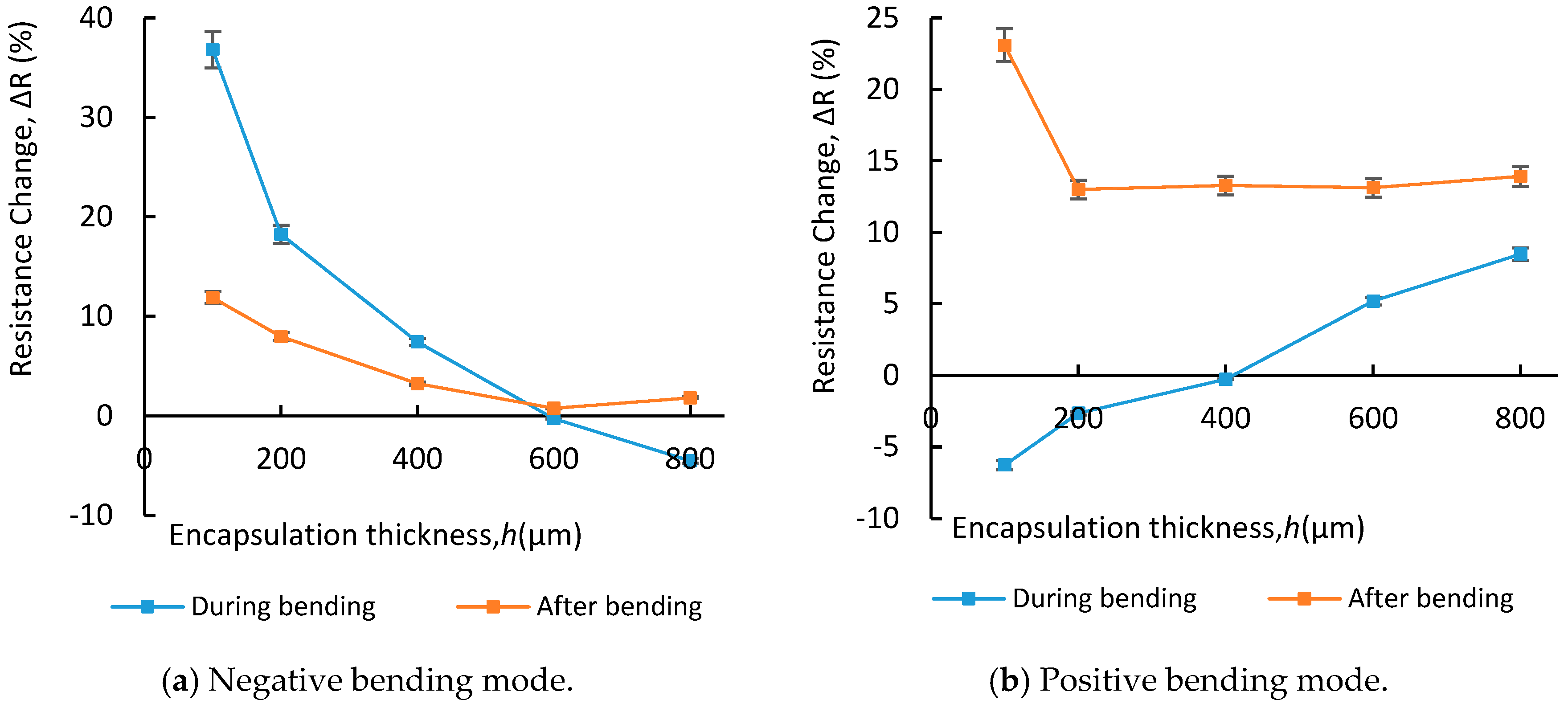
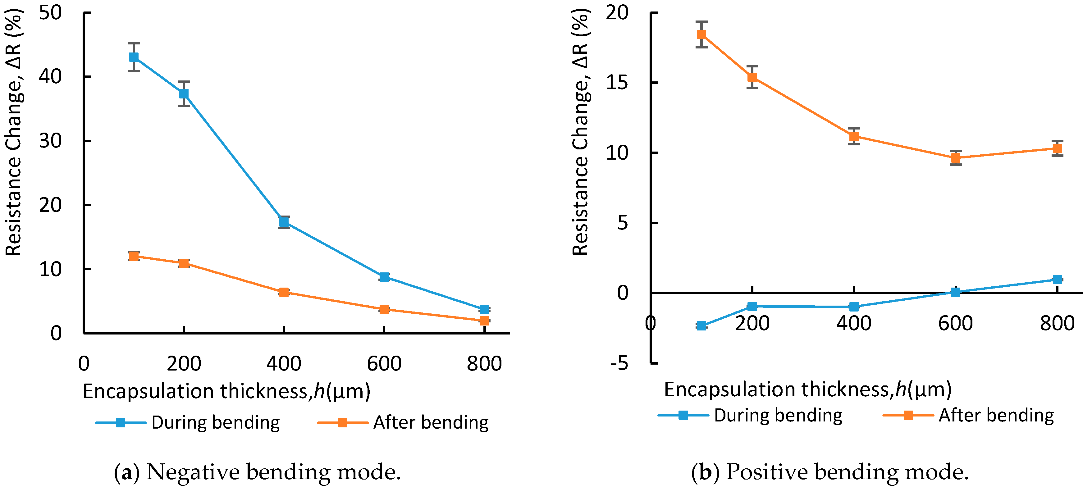
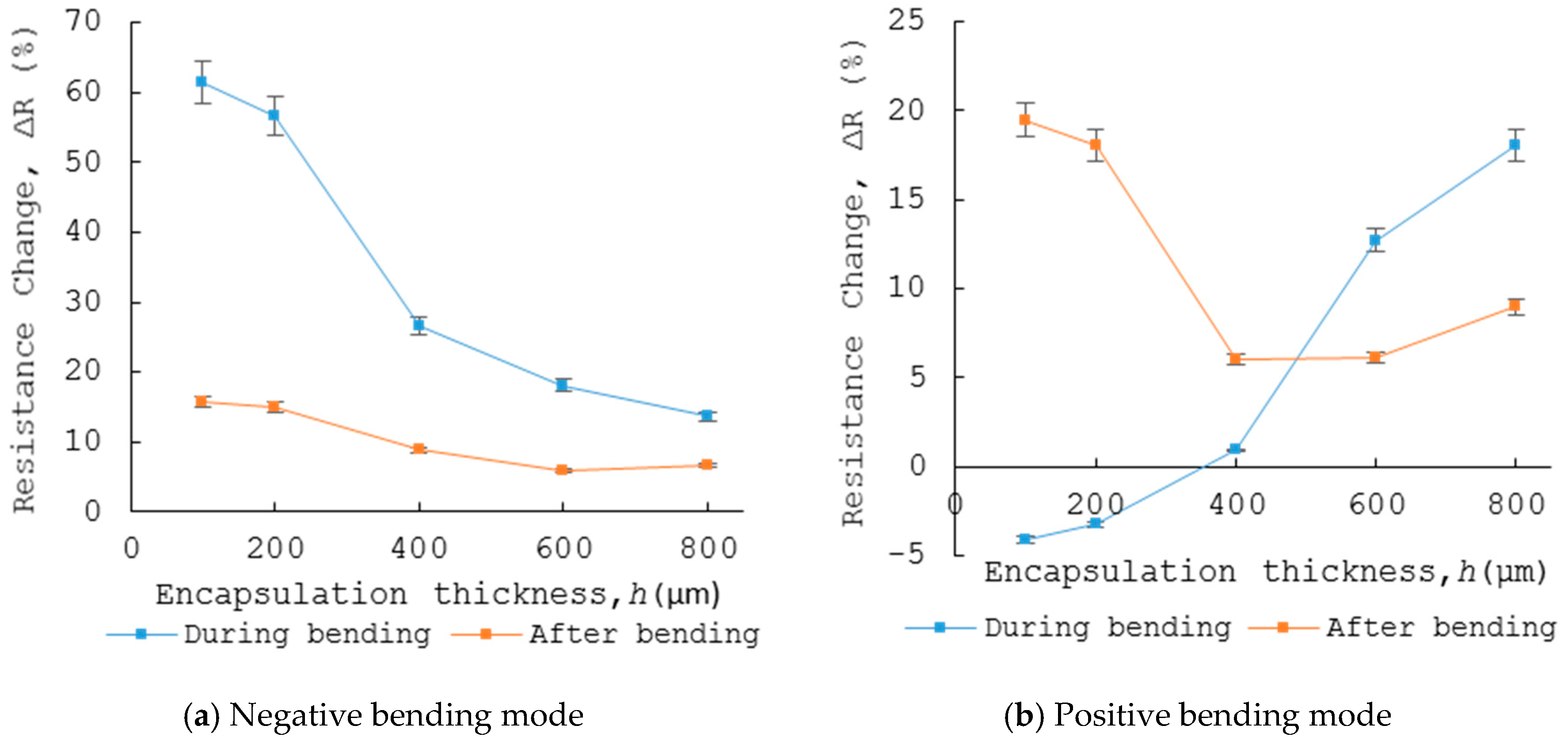
The resistance changes, averaged over two samples, from the bending test for the Bari and Escalade printed fabrics are shown in Figure 3, Figure 4 and Figure 5. These results are representative of the printed PES and Lagonda fabrics which are presented in Table 2. The results generally indicate that the printed fabrics have different NA positions for negative and positive bending. Gauges located in the proximity of these NAs exhibited the smallest mechanical strain and hence ΔR, across all the fabrics during and after bending.
In negative bending mode, after bending, the strain on the fabrics relaxes and the resistance falls but not back to its original value. In the positive bending mode, however, the gauges (Figure 3b, Figure 4b and Figure 5b) show a larger permanent increase in resistance after bending. These results indicate the strains applied during bending changes the piezoresistive gauges and as a result resistance permanently increases after straightening the samples. In all cases, the permanent change in resistance is positive irrespective to the direction of the strain during bending. In positive bending, the permanent change is larger than the change experienced during bending. Unlike the negative bending mode, the behaviour of the gauges after positive bending contradicts the NA theory. Although the reason for this is still unknown, the larger resistance change after bending could suggest a change in the microstructure of gauges during bending. Finally, whilst placing the gauge at the NA does minimize the change in resistance that occurs during both bending modes, it has little effect on the permanent change after positive bending.
The results also show that the stiffness of the fabric influences the position of the NA; hence the thickness of encapsulation required to protect any printed active layer. It was expected that as the elastic modulus of the fabric increases, the thickness, h of encapsulation required to locate the gauges on the NA would also increase. For example, a smaller h ≈ 600 µm was needed on Bari fabric (ET = 400 MPa) compared to an h > 800 µm required on the stiffer Escalade fabric (ET = 550 MPa) as shown in Figure 3a and Figure 4a. However this was not the case on fabrics whose ET is significantly different along the warp and weft directions. For example in the Escalade fabric, it was observed that in negative bending mode, the required encapsulation remained unchanged irrespective of the direction the gauge was printed as shown in Figure 4a and Figure 5a. While this indicates that the stiffer yarn in the fabric dominates the fabric elastic behaviour especially due to the impregnation of the printed interface, a further study of the elastic behaviour of such fabrics is still required.
The results also show that the fabrics (Bari and PES) with equal tensile modulus in the warp and weft directions each had two NA positions. The fabrics (Escalade and Lagonda) with different tensile modulus in these directions, each had four NA positions. This shows that the number of NAs in a fabric depends on its stiffness characteristics. This means the encapsulation thickness is a compromise between the requirements for the different NA positions; and the active layer should be located as close as possible to the average NA position in the fabric.
Future work will focus on developing a model that can predict the encapsulation thicknesses needed to locate conductors on the neutral axis of printed e-textiles. This will benefit rapid prototyping of printed e-textiles by reducing the cost and time of making prototypes. Samples will be cycled multiple times to evaluate the long-term effect of bending the inks.
Conflicts of Interest
The authors declare no conflict of interest.
References
- Yang, K.; Torah, R.N.; Beeby, S.; Tudor, J. Investigation of screen printed flexible silver to achieve washable conductors on textiles. In Proceedings of the LOPE-C 2013: Large-Area, Organic & Printed Electronics Convention, Munchen, Germany, 11–13 June 2013; p. 12. [Google Scholar]
- Yang, K.; Torah, R.; Wei, Y.; Beeby, S.; Tudor, J. Waterproof and durable screen printed silver conductive tracks on textiles. Text. Res. J. 2013, 83, 2023–2031. [Google Scholar] [CrossRef]
- Paul, G.; Torah, R.; Yang, K.; Beeby, S.; Tudor, J. An investigation into the durability of screen-printed conductive tracks on textiles. Meas. Sci. Technol. 2014, 25, 025006. [Google Scholar] [CrossRef]
- Komolafe, A.O.; Torah, R.N.; Yang, K.; Tudor, J.; Beeby, S.P. Durability of screen printed electrical interconnections on woven textiles. In Proceedings of the 2015 IEEE 65th Electronic Components and Technology Conference (ECTC), San Diego, CA, USA, 26–29 May 2015; pp. 1142–1147. [Google Scholar]
Figure 1.
Printed fabric assembly showing the ideal position of the strain gauge.

Figure 2.
Printed Bari fabric in negative bending (a) and positive bending (b) modes.

Figure 3.
Resistance changes for gauges on Bari fabric along warp and weft weave.

Figure 4.
Resistance changes for gauges on Escalade fabric along warp weave (or stiff) direction.

Figure 5.
Resistance changes for gauges on Escalade fabric along weft weave (or elastic) direction.


Table 1.
Physical properties of fabrics and thicknesses of printed films.
| Fabric Type | Twill | Percentage Blend (Polyester/Cotton/Lycra) % | Tensile Modulus, ET (MPa) | Thickness (µm) | ||||
|---|---|---|---|---|---|---|---|---|
| Warp | Weft | Fabric | Interface | Gauge | Encapsulation | |||
| Bari | 2 × 1 | 65/35/0 | 400 | 400 | 324 | 109 | 5 | 100–800 |
| PES | 2 × 1 | 100/0/0 | 617 | 617 | 60 | |||
| Lagonda | 2 × 1 | 30/40/30 | 622 | 79 | 290 | |||
| Escalade | 3 × 1 | 16/46/48 | 550 | 102 | 400 | |||
Table 2.
Resistance change in strain gauges at different encapsulation thickness, h.
| h (µm) | Resistance Change, ΔR (%) PES Fabric | Resistance Change, ΔR (%) Lagonda Fabric (Weft) | Resistance Change, ΔR (%) Lagonda Fabric (Warp) | |||||||||
|---|---|---|---|---|---|---|---|---|---|---|---|---|
| Negative Bending | Positive Bending | Negative Bending | Positive Bending | Negative Bending | Positive Bending | |||||||
| Dur. | Aft. | Dur. | Aft. | Dur. | Aft. | Dur. | Aft. | Dur. | Aft. | Dur. | Aft. | |
| 100 | 22.9 | 8.13 | −2.68 | 1.54 | 61.97 | 15.26 | −8.27 | 8.88 | 61.95 | 12.18 | −8.24 | 16.86 |
| 200 | 11.5 | 5 | −0.96 | 1.63 | 48.41 | 12.69 | −5.4 | 10.87 | 45.24 | 11.36 | −6.74 | 14.3 |
| 400 | 3.92 | 1.97 | −0.12 | 0.5 | 34.42 | 7.79 | 1.39 | 3.39 | 33.74 | 7.56 | −3.06 | 8.17 |
| 600 | −1.62 | 0.73 | 3.53 | 0.98 | 17.75 | 6.69 | 17.4 | 9.1 | 11.92 | 5.07 | −4.78 | 12.89 |
| 800 | −2.69 | 1.5 | 12.47 | 5.73 | 9.91 | 3.86 | 41.35 | 23.8 | 5.24 | 2.92 | −2.99 | 13.54 |
Publisher’s Note: MDPI stays neutral with regard to jurisdictional claims in published maps and institutional affiliations. |
© 2017 by the authors. Licensee MDPI, Basel, Switzerland. This article is an open access article distributed under the terms and conditions of the Creative Commons Attribution (CC BY) license (https://creativecommons.org/licenses/by/4.0/).
Share and Cite
MDPI and ACS Style
Komolafe, A.; Torah, R.; Tudor, J.; Beeby, S. Improving the Durability of Screen Printed Conductors on Woven Fabrics for E-Textile Applications. Proceedings 2017, 1, 613. https://doi.org/10.3390/proceedings1040613
AMA Style
Komolafe A, Torah R, Tudor J, Beeby S. Improving the Durability of Screen Printed Conductors on Woven Fabrics for E-Textile Applications. Proceedings. 2017; 1(4):613. https://doi.org/10.3390/proceedings1040613
Chicago/Turabian StyleKomolafe, Abiodun, Russel Torah, John Tudor, and Steve Beeby. 2017. "Improving the Durability of Screen Printed Conductors on Woven Fabrics for E-Textile Applications" Proceedings 1, no. 4: 613. https://doi.org/10.3390/proceedings1040613