Contactless Interrogation System for Capacitive Sensors with Time-Gated Technique †


Department of Information Engineering, University of Brescia, 25123 Brescia, Italy
*
Author to whom correspondence should be addressed.
†
Presented at the Eurosensors 2017 Conference, Paris, France, 3–6 September 2017.
Proceedings 2017, 1(4), 395; https://doi.org/10.3390/proceedings1040395
Published: 8 August 2017
(This article belongs to the Proceedings of Proceedings of Eurosensors 2017, Paris, France, 3–6 September 2017)
Abstract
:This paper presents a measurement technique and system for the contactless interrogation of capacitive sensors via electromagnetic coupling. The interrogation unit employs a primary coil to periodically excite the capacitive sensor connected to a secondary coil forming an LC resonant circuit. When the excitation to the primary coil is switched off the damped response of the LC circuit is detected. As a fundamental advantage compared to techniques based on reflected impedance, this approach ensures that the readout frequency is to first order independent of the interrogation distance between the two coils. The system has been tested with reference capacitors and with a capacitive liquid level sensor. The experimental results are in a good agreement with theoretical expectations and show a sensitivity of about −23 kHz/pF at 5.4 MHz and the possibility to operate with interrogation distances up to few centimeters.
1. Introduction
Capacitive sensing is increasingly investigated due to its versatility. Besides sensing applications for pressure, position, proximity, liquid level measurement and material analysis, capacitive techniques are promising for contactless operation. Passive wireless humidity sensors [1] and non-contact passive electromagnetic interfaces especially dedicated to capacitive sensors [2,3,4] have been demonstrated, but these adopted measurement techniques generally suffer from a dependency on the interrogation distance, which makes them difficult to apply in real operating conditions. Differently, this paper presents a contactless interrogation system for capacitive sensors that exploits a specific time-gated technique firstly developed for piezoelectric resonant sensors [5,6]. As a fundamental advantage compared to techniques based on reflected impedance, this novel technique ensures that the readout frequency is to first order independent of the interrogation distance between the two coils. The effectiveness of the proposed interrogation system has been tested by emulating a capacitive sensor with different capacitance values connected to the resonant circuit. Thereafter, a test application using capacitive liquid level sensor has been proposed.
2. Time-Gated Contactless Interrogation System for Capacitive Sensors
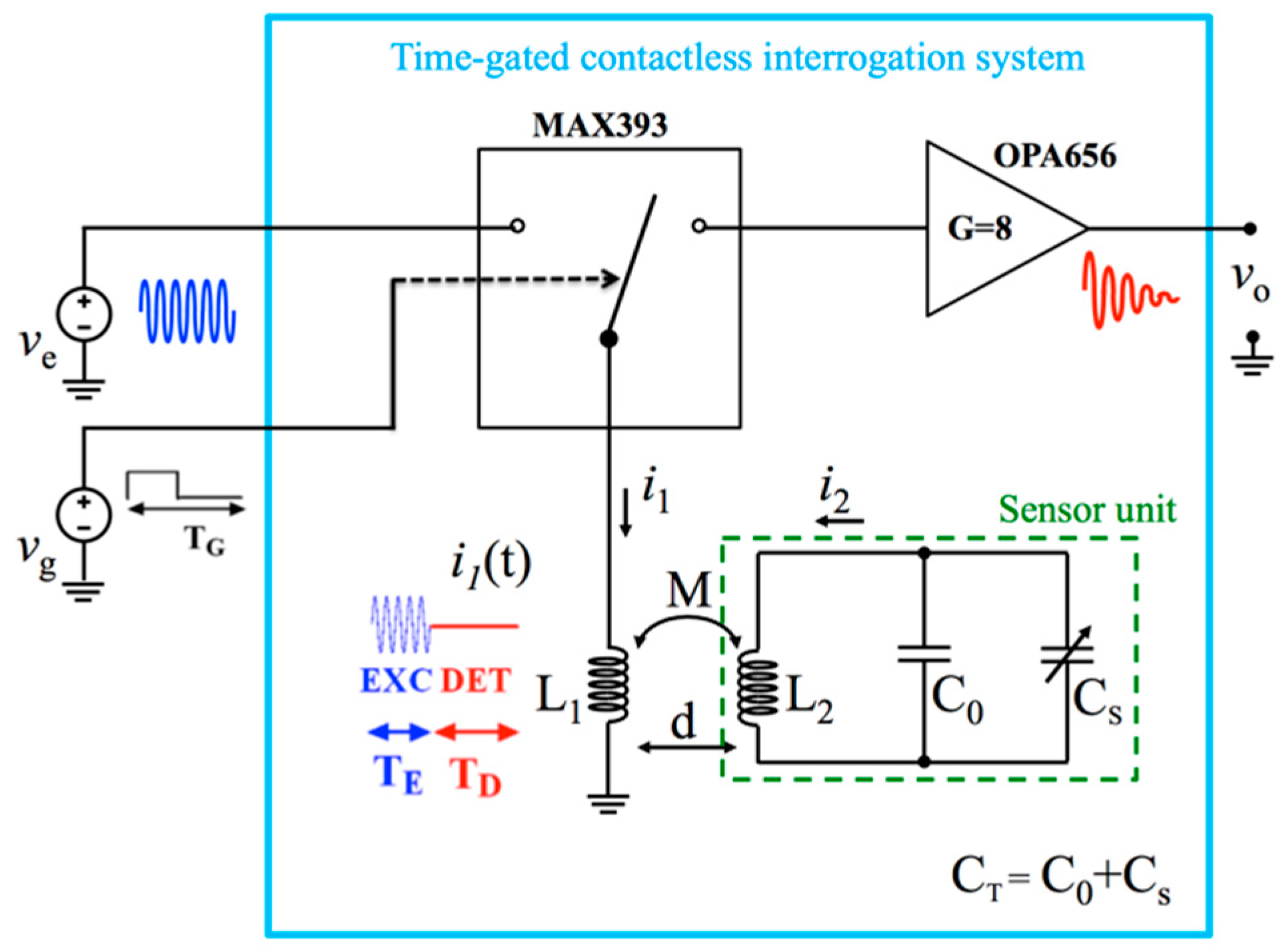
Figure 1 shows the block diagram of the interrogation system which implements the time-gated technique. The technique works in two interleaved phases, namely excitation and detection phases. The rectangular signal vg(t) is used to switch between the excitation and detection phases. During the excitation phase, the primary coil L1 is connected to the sinusoidal signal ve(t) at frequency fe to excite the sensor unit which is composed of a capacitive sensor CS connected to the secondary coil L2 forming a LC resonant circuit. With the additional tuning capacitance C0 the resonant frequency fR is set to:
where CT = CS + C0. With the values of CS and C0 adopted in this study fR is in the order of 5 MHz. During the detection phase, the excitation signal is turned off and L1 is connected to the high-impedance input of the readout amplifier with gain G = 8 that virtually sinks no current. Therefore, the output signal vO(t) starting at the beginning of the detection phase results in a damped sinusoid as follows:
where the damped resonant frequency fD can be expressed as a function of fR and the quality factor Q of the LC circuit as follows:
In Equation (2) the amplitude and phase coefficients Am and θm are functions of both the initial conditions taken at the end of the excitation period and the electrical parameters of the system composed of L1, L2 and the capacitive sensor. The exponential decay time τ is related to the quality factor by Q = πfRτ; while Q is determined mainly by the parasitic series resistance of L2 [5,6]. The additional term in Equation (2) is a voltage pulse which accounts for the initial current in L1. From Equation (2) it can be observed that for the voltage sensed across the primary coil the mutual inductance M, which in turn depends on the distance d, only acts as an amplitude scaling factor, affecting neither the frequency nor the decay time of the readout signal. Because the measurement technique exploits the free response of the resonator which is independent from the type of excitation, the exact knowledge of the LC resonant frequency fR is not in principle required. However, if fe is close to fR an improvement in the signal-to-noise ratio during the detection phase, and hence in the maximum interrogation distance d, can be attained. In addition it can be seen from Equation (3) that for sufficiently high values of Q, fD ≈ fR. Under these circumstances, for incremental variations dCS, Equation (1) can be linearized, obtaining the sensitivity of fD to the sensor capacitance CS as:
3. Experimental Results
Figure 2 shows the measured gate signal vg(t) and the output voltage vO(t) obtained with a capacitance CT = 102 pF and interrogation distance d = 20 mm. The frequency fD is measured during the detection phase by a high-resolution counter triggered by the gate signal using a measurement time tM = 3.2 µs starting after a delay time tD to avoid the initial electrical ringing given by L1 and the input capacitance of the amplifier. A quality factor Q = 60 has been estimated from the exponential decaying envelope giving a relative deviation (fR−fD)/fD of less than 35 ppm.
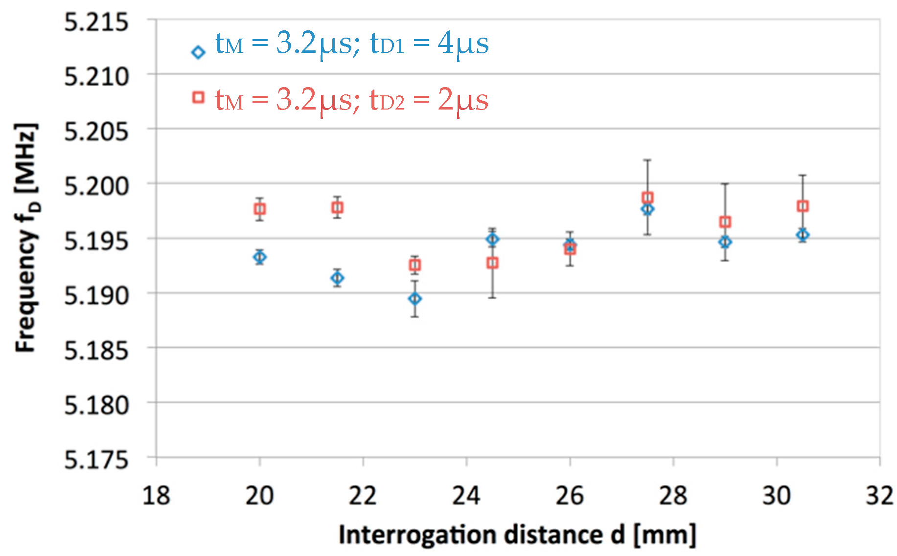
The system was then tested by varying the interrogation distance d and with different time delays tD. Figure 3 shows only slight variations of fD in the distance range between 20 and 30 mm, confirming the expected independence from d. Figure 4 reports the measured and theoretical values of fD versus the total capacitance CT, ranging from 102 to 110 pF. Reference measurements of CT and L1 = 8.48 μH have been done with an impedance analyzer (HP4194A). Across such range, a linear trend with sensitivity of about −23 kHz/pF has been obtained in good agreement with the theoretical value of about −25 kHz/pF.
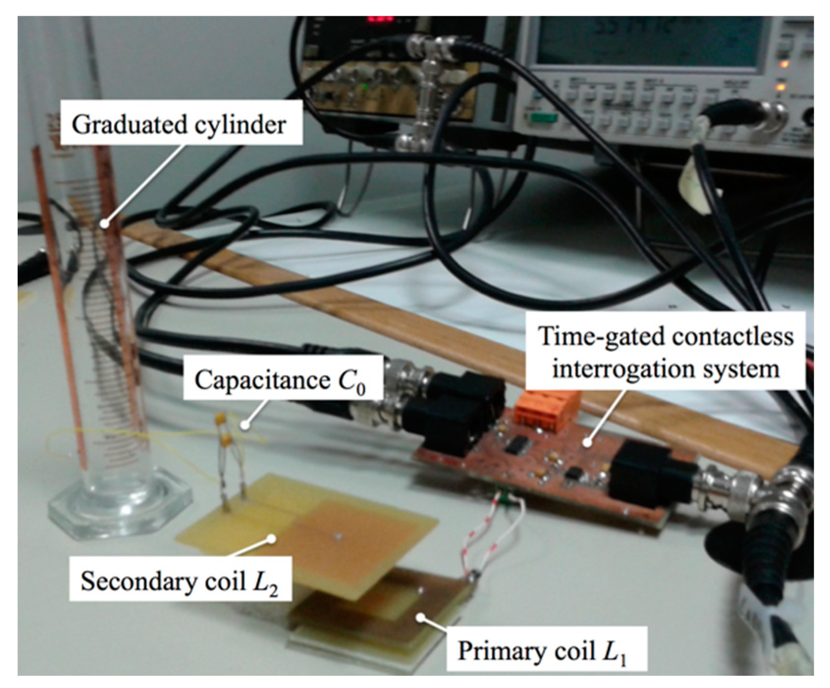
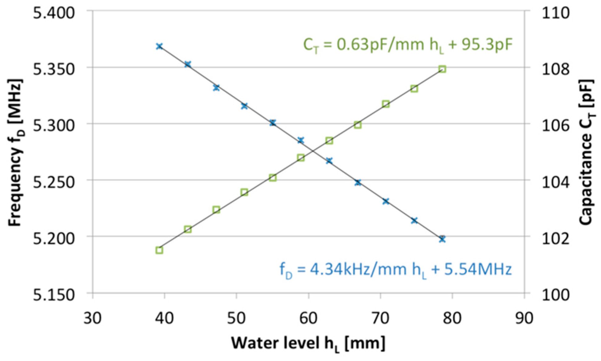
In addition, contactless liquid level measurement is performed as the test application of a capacitive sensor with contactless interrogation. A capacitive level sensor CS has been built with a graduated cylinder with two copper faced electrodes placed outside. The secondary coil L2 and a tuning capacitor C0 = 94 pF are connected to CS thus forming the sensor unit. Figure 5 reports a picture of the contactless interrogation system and the sensor unit with the graduate cylinder. The secondary coil L2 has been placed at a fixed distance of approximately 30 mm from the primary coil L1 for liquid level measurement. Pouring liquid (water) gradually on the cylinder increases the sensor capacitance and a corresponding decrease occurs in the frequency fD. The water level inside the cylinder was increased in steps of 3 mm from 40 mm up to about 80 mm. Figure 6 shows the measured frequency fD and total capacitance CT as a function of water level hL. In the explored liquid level range, linearity has been obtained with sensitivities ΔfD/ΔhL and ΔCT/ΔhL of about −4.34 kHz/mm and 0.63 pF/mm, respectively.
4. Conclusions
A contactless interrogation technique and system for capacitive sensors have been presented. The sensor unit is composed of the capacitive sensor connected to a tuning capacitor and a coil forming a LC resonant circuit. The interrogation system measures the resonant frequency of the LC network by exploiting a distance-independent time-gated technique. Experimental results show that measurements are independent of the interrogation distance between the primary coil and the coil on the sensor unit in the range between 20 and 30 mm. By varying the sensor capacitance, a sensitivity of about −23 kHz/pF has been measured at a resonant frequency around 5.4 MHz. A test application using a capacitive liquid level sensor has been presented, obtaining a linear trend with sensitivity ∆fD/∆hL of about −4.34 kHz/mm. The experimental results foresee the possibility to apply the proposed technique to different types of capacitive sensors fostering, among others, applications based on low-cost printed labels as sensor units.
Conflicts of Interest
The authors declare no conflict of interest.
References
- Zhang, C.; Wang, L.F.; Huang, J.Q.; Huang, Q.A. An LC-Type Passive Wireless Humidity Sensor System With Portable Telemetry Unit. J. Microelectromech. Syst. 2015, 24, 575–581. [Google Scholar] [CrossRef]
- Jachowicz, R.S.; Wójtowicz, G.; Weremczuk, J. A non-contact passive electromagnetic transmitter to any capacitive sensor—Design, theory, and model tests. Sens. Actuators A Phys. 2000, 85, 402–408. [Google Scholar] [CrossRef]
- Nopper, R.; Niekrawietz, R.; Reindl, L. Wireless Readout of Passive LC Sensors. IEEE Trans. Instrum. Meas. 2010, 59, 2450–2457. [Google Scholar] [CrossRef]
- Sauer, S.; Marschner, U.; Adolphi, B.; Clasbrummel, B.; Fisher, W.J. Passive Wireless Resonant Galfenol Sensor for Osteosynthesis Plate Bending Measurement. IEEE Sens. J. 2011, 12, 1226–1233. [Google Scholar] [CrossRef]
- Ferrari, M.; Baù, M.; Tonoli, E.; Ferrari, V. Piezoelectric Resonant Sensors with Contactless Interrogation for Mass Sensitive and Acoustic-Load Detection. Sens. Actuators A Phys. 2013, 202, 100–105. [Google Scholar] [CrossRef]
- Baù, M.; Ferrari, M.; Ferrari, V. Analysis and Validation of Contactless Time-Gated Interrogation Technique for Quartz Resonator Sensors. Sensors 2017, 17, 1264. [Google Scholar] [CrossRef] [PubMed]
Figure 1.
Block diagram of the time-gated contactless interrogation system. The sensor unit is represented by the secondary coil L2 and the capacitance CT = C0 + CS, where CS represents the sensor capacitance.
Figure 1.
Block diagram of the time-gated contactless interrogation system. The sensor unit is represented by the secondary coil L2 and the capacitance CT = C0 + CS, where CS represents the sensor capacitance.

Figure 2.
Measured output voltage vO(t) versus time during the detection phase obtained with interrogation distance d = 20 mm. The quality factor Q can be estimated from the exponential decaying envelope.
Figure 2.
Measured output voltage vO(t) versus time during the detection phase obtained with interrogation distance d = 20 mm. The quality factor Q can be estimated from the exponential decaying envelope.

Figure 3.
Measured damped frequency fD as a function of the interrogation distance d with tM = 3.2 μs and different delay times tD1 = 4 μs and tD2 = 2 μs.
Figure 3.
Measured damped frequency fD as a function of the interrogation distance d with tM = 3.2 μs and different delay times tD1 = 4 μs and tD2 = 2 μs.

Figure 4.
Measured and theoretical values of the damped frequency fD as a function of the total capacitance CT.
Figure 4.
Measured and theoretical values of the damped frequency fD as a function of the total capacitance CT.

Figure 5.
Experimental setup with the time-gated contactless interrogation system, and the graduated cylinder used for liquid-level measurements.
Figure 5.
Experimental setup with the time-gated contactless interrogation system, and the graduated cylinder used for liquid-level measurements.

Figure 6.
Measured damped frequency fD and measured total capacitance CT as a function of the water level hL.
Figure 6.
Measured damped frequency fD and measured total capacitance CT as a function of the water level hL.

Publisher’s Note: MDPI stays neutral with regard to jurisdictional claims in published maps and institutional affiliations. |
© 2017 by the authors. Licensee MDPI, Basel, Switzerland. This article is an open access article distributed under the terms and conditions of the Creative Commons Attribution (CC BY) license (https://creativecommons.org/licenses/by/4.0/).
Share and Cite
MDPI and ACS Style
Masud, M.; Baù, M.; Demori, M.; Ferrari, M.; Ferrari, V. Contactless Interrogation System for Capacitive Sensors with Time-Gated Technique. Proceedings 2017, 1, 395. https://doi.org/10.3390/proceedings1040395
AMA Style
Masud M, Baù M, Demori M, Ferrari M, Ferrari V. Contactless Interrogation System for Capacitive Sensors with Time-Gated Technique. Proceedings. 2017; 1(4):395. https://doi.org/10.3390/proceedings1040395
Chicago/Turabian StyleMasud, Mehedi, Marco Baù, Marco Demori, Marco Ferrari, and Vittorio Ferrari. 2017. "Contactless Interrogation System for Capacitive Sensors with Time-Gated Technique" Proceedings 1, no. 4: 395. https://doi.org/10.3390/proceedings1040395