Proceeding Paper

A Piezoelectric Micromachined Ultrasound Transducers (pMUT) Array, for Wide Bandwidth Underwater Communication Applications †

1
ESAT-MICAS/KU Leuven, B-3001 Heverlee, Belgium
2
Institute for Materials Research (IMO), Hasselt University, Wetenschapspark 1, B-3590 Diepenbeek, Belgium
3
IMOMEC, IMEC vzw, Wetenschapspark 1, B-3590 Diepenbeek, Belgium
*
Author to whom correspondence should be addressed.
Presented at the Eurosensors 2017 Conference, Paris, France, 3–6 September 2017.
Proceedings 2017, 1(4), 364; https://doi.org/10.3390/proceedings1040364
Published: 7 August 2017
(This article belongs to the Proceedings of Proceedings of Eurosensors 2017, Paris, France, 3–6 September 2017)

Abstract

:
This paper presents an array of five aluminum nitride (AlN) based piezoelectric micromachined ultrasound transducers (pMUTs) with different dimensions operating at 540–2360 kHz in air. Due to the damping effect of water or oil on the vibration of each individual pMUT, their frequency response tends to merge and significantly increases the bandwidth of the pMUTs array. The device is fabricated based on the deep reactive ion etching (DRIE) process on the backside of an SOI wafer to realize the circular diaphragms. Theoretical calculations, measured frequency response, simulation results, and detail of the fabrication are explained in this paper.

1. Introduction

Recently, the interest in piezoelectric micromachined ultrasound transducers (pMUTs) is growing. PMUTs are a good alternative for conventional bulk piezoelectric transducers because of their small element size, low power consumption and ease of fabrication of large arrays for imaging and communication applications. However, one of the main criticisms on pMUTs are their relatively narrow bandwidth compared to Capacitive Micromachined Ultrasound Transducers (cMUT) or bulk piezoelectric transducers. There are some recent reports on the fabrication of wide bandwidth pMUT, based on their higher mode of vibration [1]. A second or higher mode of vibration of a rectangular or a circular transducer behaves as a dipole, in which each two adjacent lobes of vibration are 90° out of phase, leading to a destructive effect in the normal direction, hence it radiates poorly. Moreover, higher modes have a much higher resonance frequency and vibrate with lower amplitude than the first mode, which causes them to behave in a nonuniform and sparse frequency response. In this paper, we introduce an array of five pMUTs with different dimensions and as a result different resonance frequencies. The operation of the proposed pMUT array under a viscose medium, leads to damping of the resonance and widening of the bandwidth of each individual pMUT in the array, which by a deliberate design may merge and widen the overall array bandwidth.

2. Materials and Methods

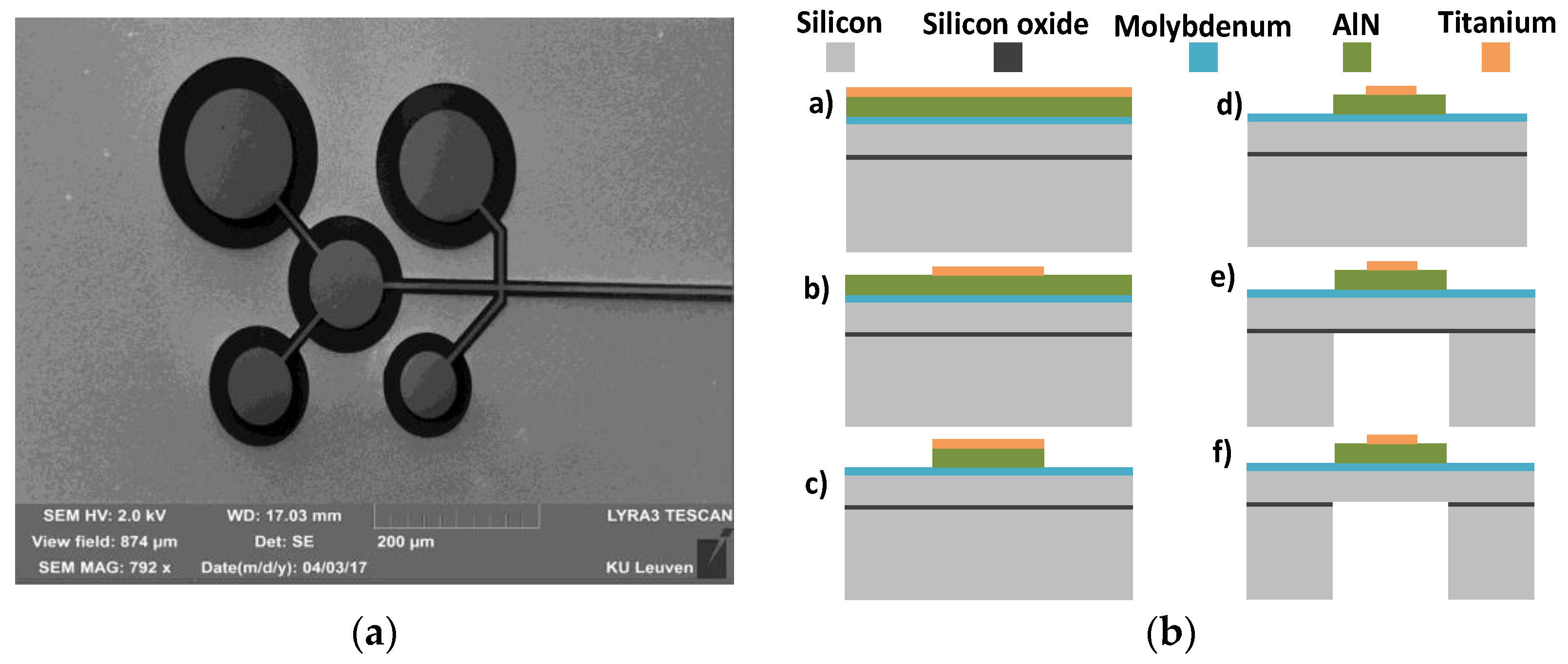
2.1. Design and Fabrication

An array of five individual pMUTs with different diameters, listed in Table 1, were fabricated, where each pMUT covers a part of the frequency response of the array.
The resonance frequency of a multi-layer membrane can be proven to follow this Equation (1):
f = 1 2 π 2 a 2 ( 0 h E ( z z 0 ) 2 1 ν ( z ) 2 d z ρ i h i ) 1 / 2 .
in which, a is the radius of the membrane, E is the Young modulus, ν is the Poisson ratio, ρ i is the density of the layer i, h i is the thickness of the layer i, and is a constant dependent to the mode of vibration. In order for all the pMUTs in the array to produce a uniform pressure beam pattern, they should physically be as close together as possible. The pMUT3, which has the center frequency in the frequency response of the array, is placed in the center of the pMUT by keeping a 30 µm distance from adjacent pMUTs, as shown in Figure 1a.
The first step in the fabrication of the pMUT array is the deposition of 250 nm of Molybdenum as the bottom electrode, 1 µm of Aluminum nitride (AlN) as the piezoelectric material, and 200 nm Titanium as the top electrode. The Ti layer is patterned to be used as the hard mask for the AlN etching. AlN is wet etched in a TMAH based developer at 60 °C, which was shown to create the least under etching possible [2]. Etching the AlN in an identical size as the membrane, releases the stress at the edge of the membrane, which causes to have more deflection during vibration. The Ti layer is patterned again to cover about 70% of the membrane area, where the stress changes from tensile to compressive [3]. This prevents the compressive region of the membrane to reduce the bending moment and decrease the deflection. As the last step in the fabrication, the membrane is released by deep reactive ion etching (DRIE) process and the buried oxide (BOX) is removed, respectively. Since the etch rate of the largest membrane is higher than the smallest membrane in DRIE, we used low RF frequency in order to avoid the notching effect while the smallest membrane is still being etched and the biggest one has reached the BOX [4]. The overall fabrication process is shown in Figure 1b.

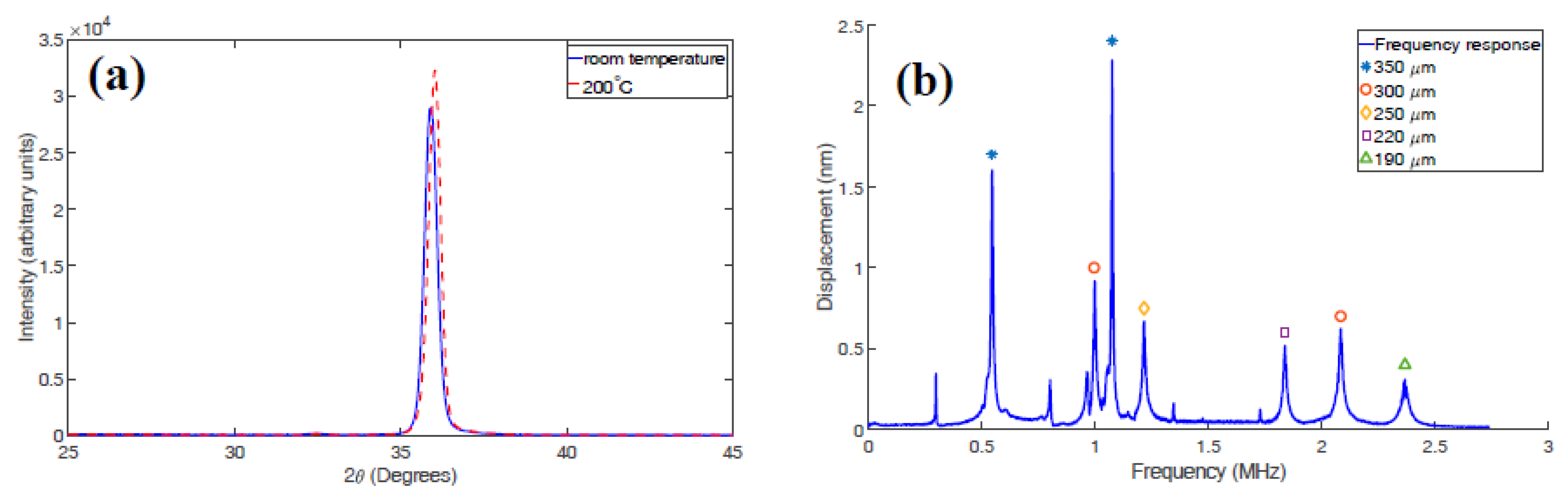
2.2. AlN Piezoelectric Material

AlN was deposited by reactive pulsed-DC magnetron sputtering of an Al target in a nitrogen atmosphere, at a pressure of 3 µbar, 850 W power, 200 °C substrate temperature, and 4 cm substrate-to-target distance. We found that the elevated temperature during sputtering of the AlN improves the crystallinity significantly, although at room temperature (002) orientation in the crystal lattice was obtained too. This is proven by the XRD pattern, Figure 2a, and the fact that the rocking curve of the deposited AlN at 200 °C is 0.4° smaller than the one at room temperature.

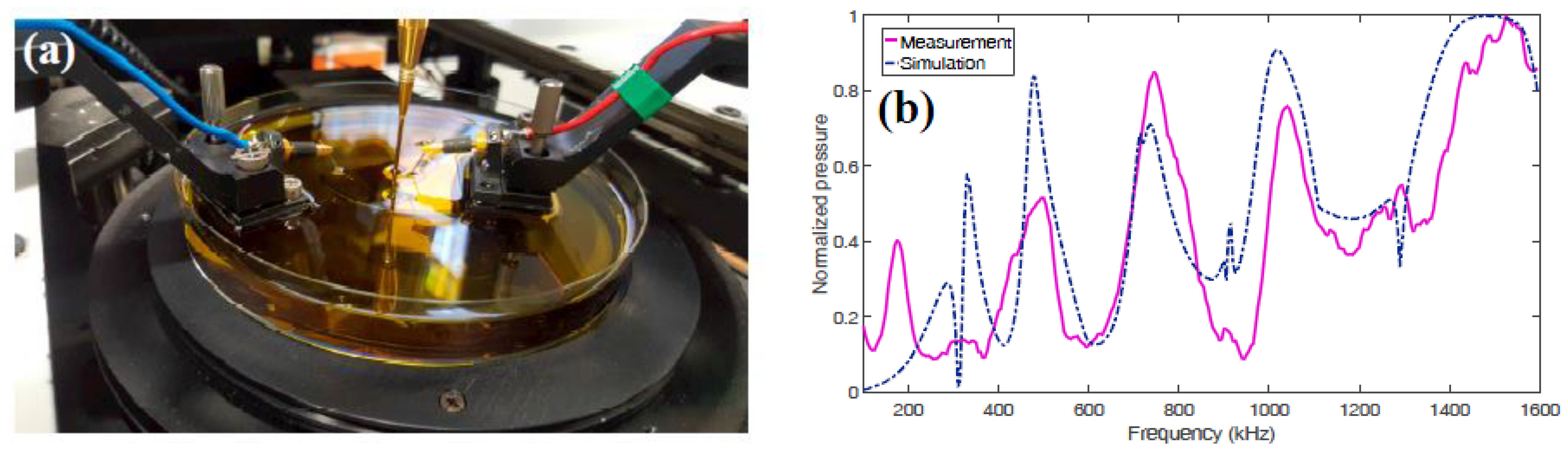
3. Results and Discussions

The frequency response of the pMUTs were measured by laser doppler vibrometer (LDV Polytec MSA-500), and is shown in Figure 2b. For 350 µm and 300 µm pMUTs there are two resonance frequencies, which are the first and the second resonance mode, respectively. The pressure measurement of the array was performed in olive oil to avoid electrical conduction between electrodes [5]. The needle hydrophone (Precision Acoustics Ltd., Dorchester, UK) is placed on top of the array by means of a micro-positioner, as shown in Figure 3a. Figure 3b shows the measured and simulated generated pressure by the fabricated pMUT array at the frequency range of 100–1600 kHz. There are three reasons why the measured resonance frequencies of Figure 2b are different from the simulated ones in Figure 3b. The first is caused by the DRIE process, in which some membranes can be etched more than the others (in the case of a thin BOX layer), so that the resonance frequency deviates from the expected value. The second reason is that the residual stress in the layers tends to increase the resonance frequency by introducing a bending moment to the membrane [6]. The third reason is the fact that the pressure measurement is performed in oil, while the simulation is made considering water environment.
It was shown that the transmitted power from an ultrasound transducer can be calculated by the following equation [7]:
Π = 2 π a 2 Z 0 k 2 a 2 + j k a 2 / R 1 + k 2 a 2 | v R 2 ( a ) |
where a is the radius of the transducer, Z 0 is the acoustic impedance of the medium, k is the wavenumber, R is the distance from center of the transducer, and v R is the speed of the vibration. As it shows, to have efficient excitation of acoustic waves, k a should be larger than one, i.e., the diameter of the transducer should be in the order of half a wavelength or more. Hence, we chose 5 µm as the thickness of the silicon membrane, which is relatively thick with respect to other designs, in order to have larger diameter with same resonance frequency as a thin membrane.
As shown in Figure 3b, the pressure amplitude is increasing by increasing the frequency. This can be explained by the equation of the generated pressure of a circular ultrasound transducer along its normal axis [8]:
P ( r ) = 2 ρ 0 c U 0 | sin { 1 2 k r [ 1 + ( a / r ) 2 1 ] } |
If we substitute Equation (1) solved for a in Equation (3), we find that the pressure amplitude increases by increasing the frequency. If the working frequency in a viscose medium is increased up to about 20 MHz or more, the diameter of the transducer tends to be in the range of half a wavelength with reasonable thickness of the membrane. In this case, the transducer is ideal for a real acoustic power transmission into the medium. This is why most of the ultrasound transducers for biomedical imaging or any other short-range imaging applications use high working frequencies. However, 20 MHz or more is not usable for communication, since the absorption of ultrasound wave by water or any other viscose medium does not let the wave to travel a long distance.

4. Conclusions

A wide bandwidth pMUT array was designed and fabricated based on AlN as piezoelectric material. The array consists of five individual pMUTs with different diameter dimensions to have several resonance frequencies in its frequency response. The resonance frequency of each pMUT in the array is widened by the damping effect of water or oil while it is submerged, and leads to widen the frequency response of the entire array. The frequency response was measured by LDV and the generated pressure was measured by a needle hydrophone in vegetable oil. It was shown that there are five resonance frequencies in the frequency response (100–1.6 MHz) respect to the generated pressure, each with 50–150 kHz individual bandwidth.

Acknowledgments

This work was supported by the European Union’s Horizon 2020 research and innovation program under grant agreement No. 665347. P.P. is a Postdoctoral Fellow of the Research Foundation Flanders (FWO).

Conflicts of Interest

The authors declare no conflict of interest.

References

  1. Wang, T.; Kobayashi, T.; Lee, C. Micromachined piezoelectric ultrasonic transducer with ultra-wide frequency bandwidth. Appl. Phys. Lett. 2015, 106, 013501. [Google Scholar] [CrossRef]
  2. Yipeng, L.; Horsely, D.A. Modeling, Fabrication, and Characterization of Piezoelectric Micromachined Ultrasonic Transducer Arrays Based on Cavity SOI Wafers. J. Microelectromech. Syst. 2015, 24, 1142–1149. [Google Scholar]
  3. Wang, M.; Zhou, Y.; Randles, A. Enhancement of the Transmission of Piezoelectric Micromachined Ultrasonic Transducer with an Isolation Trench. J. Microelectromech. Syst. 2016, 25, 691–700. [Google Scholar] [CrossRef]
  4. Aydemir, A. Deep-Trench RIE Optimization for High Performance MEMS Microsensors. Ph.D. Thesis, Middle East Technical University, Ankara, Turkey, 2007. [Google Scholar]
  5. Yang, Y.; Tian, H.; Wang, Y.-F.; Shu, Y.; Zhou, C.-J.; Sun, H.; Zhang, C.-H.; Chen, H.; Ren, T.-L. An Ultra-High Element Density pMUT Array with Low Crosstalk for 3-D Medical Imaging. Sensors 2013, 13, 9624–9634. [Google Scholar] [CrossRef] [PubMed]
  6. Soedel, W. Vibration of Shells and Membranes under the Influence of Initial Stresses. In Vibration of Shells and Plates, 3rd ed.; Faulkner, L.L., Ed.; Marcel Dekker, Inc.: New York, NY, USA, 2004; pp. 301–318. [Google Scholar]
  7. Kino, G.S. Wave Propagation with Finite Exciting Source. In Acoustic Waves: Devicesm Imaging, and Analog Signal Processing; Simon & Schuster: New York, NY, USA, 1987; pp. 154–163. [Google Scholar]
  8. Kinsler, L.E.; Frey, A.R.; Coppens, A.B.; Sanders, J.V. Radiation and reception of acoustic waves. In Fundamental of Acoustics, 4th ed.; John Wiley & Sons, Inc.: Hoboken, NJ, USA, 2000; pp. 171–184. [Google Scholar]
Figure 1. (a) SEM image of the fabricated wide bandwidth pMUT array; (b) Fabrication process flow: (b-a) sputtering of Mo/AlN/Ti stack; (b-b) patterning Ti to be used as the hard mask for AlN; (b-c) patterning AlN; (b-d) patterning Ti as top electrode; (b-e) backside DRIE; (b-f) Buried oxide wet etching.
Proceedings 01 00364 g001
Figure 2. (a) The XRD pattern of the deposited AlN at room temperature and 200 °C; (b) The LDV measurement of the pMUT array.
Proceedings 01 00364 g002
Figure 3. (a) Pressure measurement setup by hydrophone and on chip probe; (b) The measured and simulated generated pressure by the fabricated pMUT array.
Proceedings 01 00364 g003
Table 1. Diameter size of each pMUT element in the array.
pMUT ElementDiameter Size
pMUT1190 µm
pMUT2220 µm
pMUT3250 µm
pMUT4300 µm
pMUT5350 µm
Publisher’s Note: MDPI stays neutral with regard to jurisdictional claims in published maps and institutional affiliations.

