Single-Element Omnidirectional Piezoelectric Ultrasound Transducer for under Water Communication †


1
KU Leuven, ESAT-MICAS, B-3001 Heverlee, Belgium
2
KU Leuven, Department of Mechanical Engineering, B-3001 Heverlee, Belgium
3
KU Leuven, Department of Materials Engineering, B-3001 Heverlee, Belgium
*
Author to whom correspondence should be addressed.
†
Presented at the Eurosensors 2017 Conference, Paris, France, 3–6 September 2017.
Proceedings 2017, 1(4), 363; https://doi.org/10.3390/proceedings1040363
Published: 16 August 2017
(This article belongs to the Proceedings of Proceedings of Eurosensors 2017, Paris, France, 3–6 September 2017)
Abstract
:This paper presents the design and fabrication procedure of a single-element omnidirectional piezoelectric ultrasound transducer, which can be utilized for under water communication. The transducer consists of a spherical silicon infiltrated silicon carbide (Si-SiC) body and is able to perform communication at 160 kHz with a Q factor of about 5.6 over a distance of more than one meter. The circumferential pressure amplitude of the beam pattern of the transducer varies less than 10 dB, which allows reliable communication between different transducers at an arbitrary orientation with respect to each other.
1. Introduction
The low attenuation of ultrasound signals in water, oil, human body, etc. makes it a promising alternative to electromagnetic wave communication. Therefore, ultrasound is commonly used in medical imaging and underwater communication [1]. Most of the available ultrasound transducers are based on a single element piezoelectric material producing a piston shaped actuation, although single crystal piezoelectric materials by means of array structure are utilized in medical imaging [2]. In both cases, the beam pattern of the transducer is directional. However, to cover the whole space, e.g., for 3D imaging or communication, we need very complex structures, such as mechanical rotary movement or a folded surface covered with an array of transducers, which are also limited to short distance application [3].
We proposed a new type of transducer that generates ultrasound waves by the vibration of a mechanical structure, based on the piezoelectric phenomena, for omnidirectional long distance under water communication. This work describes the design, fabrication, and results of the proposed omnidirectional transducer. Under water measurement with a hydrophone and among two similar transducers are also presented. The transducer’s fabrication is relatively cheap and it can be used in under water communication, localization, and range finding applications.
2. Materials and Methods
2.1. Design and Methodology
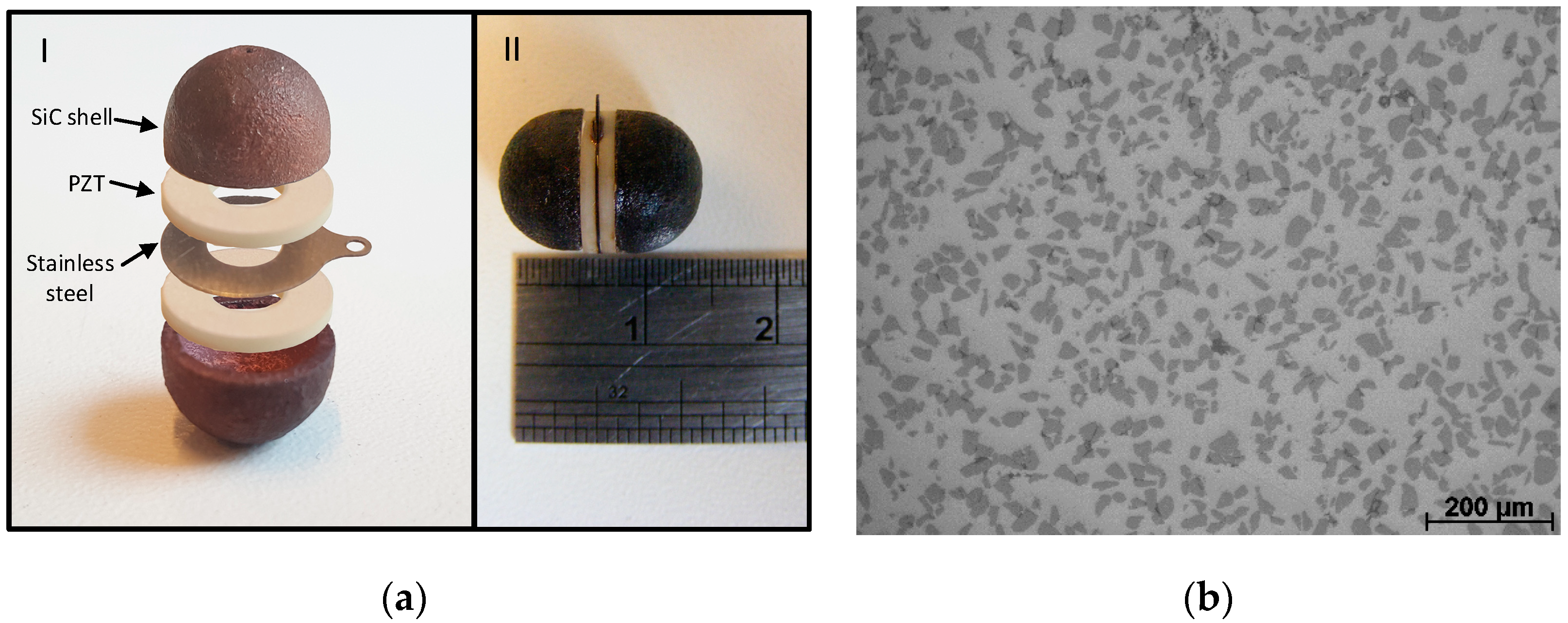
The transducer and its design architecture before integration is shown in Figure 1. It consists of two Si-SiC hemisphere shells with a thickness of 1 mm, which works as the main generator of the ultrasound wave, two PZT elements (Physik Instrumente (PI) GmbH & Co, Karlsruhe, Germany) with a thickness of 1 mm, and one 0.2 mm stainless-steel layer.
By the vibration of the piezoelectric elements, the ultrasound wave is transmitted through the Si-SiC shells and bring them to their resonance frequency. The stainless-steel layer separates the functionality of the two hemispheres by introducing a different acoustic impedance than the one of the PZT. In the case of using one PZT element without the steel layer, the acoustic power transmitted through the shells will be reduced to half.
To simplify the design procedure, we imitated the vibration of each hemisphere by a curved beam with constant curvature. The resonance frequency of such a curved beam is calculated by the following equation [4]:
where are the Young’s modulus, thickness, radius of curvature, frequency constant, and the density per unit of length of the shell, respectively. In order to keep the resonance frequency of the transducer in the range of a few hundred kHz to avoid acoustic power absorption by water at higher frequencies and to have enough space inside the transducer for electronics, the ratio had to be increased. Therefore, Si-SiC was used as the material of the shell. SiC has a Young’s modulus to density ratio of 1.11 × 10⁸–1.486 × 10⁸, depending on the production technique [5]. After diamond and boron carbide, SiC has the highest value of among all ceramics.
2.2. Fabrication and Integration
2.2.1. Additive Manufacturing of Si-SiC Hemispheres
The Si-SiC hemispheres used in this work are produced by selective laser sintering, an additive manufacturing method, whereby a structure is built up in a layer by layer fashion starting from a powder bed [5]. The process consists in 4 steps. In a first step, 33 wt % Si and 67 wt % α-SiC powders are mixed until a homogeneous Si-SiC powder mixture is obtained. This powder serves as the base material for the laser sintering. The second step consists of laser sintering of the powder mixture. In order to avoid oxidation, the process is conducted under an inert Argon atmosphere. As the laser selectively scans the powder bed, the Si in the powder mixture locally melts and resolidifies to bind the SiC grains together. This results in a porous preform hemisphere that can be transformed into a fully dense Si-SiC part. This happens in the third step by means of liquid silicon infiltration (LSI). The LSI is performed in a vacuum of 0.1 mbar in a hot press furnace. During infiltration, the laser sintered hemispheres are placed in a graphite crucible together with Si powder. The furnace is heated at 50 °C/min up to 1500 °C and held for 15 min, before cooling down naturally to room temperature. The Si in the crucible melts and infiltrates the porosity in the laser sintered parts, resulting in fully dense Si-SiC hemispheres. Figure 2 shows a light microscopy image of the produced material’s microstructure. The fourth and final step consists of finishing the hemispheres by grinding the bottom surface and make it ready for the integration with PZT and stainless-steel elements. This is done on an in-house built grinding/polishing station. Table 1 shows a comparison of the properties of the fabricated Si-SiC material with those of pure SiC.
2.2.2. Assembly of the Transducer
The assembly is done in three steps. First, each hemisphere is coated by copper thin films by RF sputtering at 200 W and pressure of 4 × 10⁻³ mbar for 20 min to increase its conductivity in order to use the shell as one of the electrodes. Second, the two piezoelectric PZT elements are attached together by a mixture of conductive CircuitWork CW2400 epoxy and medium viscosity Epotek 353ND epoxy, which are both cured at 100 °C. This is noticeably lower than the curie temperature of the PZT and does not damage the PZT element. Third, the PZT elements and the hemispheres are assembled together by Epotek 353ND and cured and hardened in an oven in ambient atmosphere while clamped together.
3. Results and Discussions
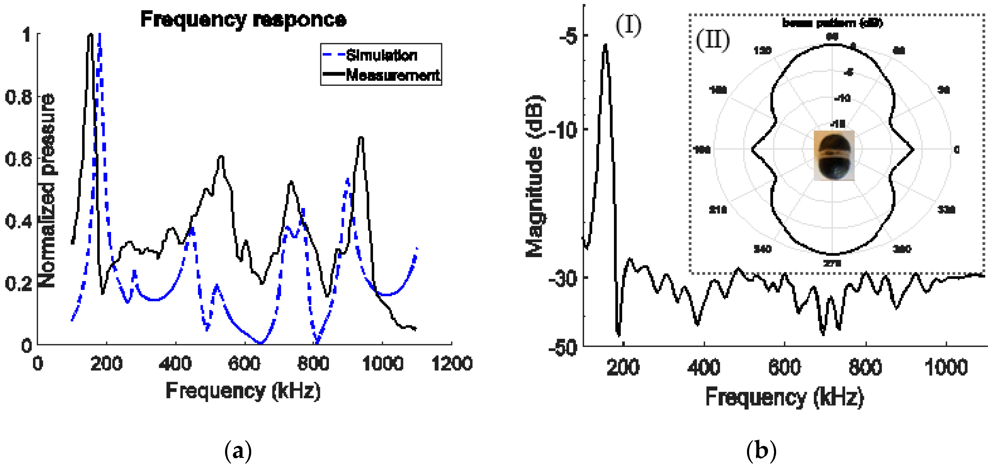
The functionality of the transducer has been measured in a 300 L deionized water tank equipped with a needle hydrophone (Precision Acoustics Ltd., Dorchester, UK). Figure 2a shows the FEM simulation and measurement of the normalized frequency response of the transducers, which is measured by a hydrophone placed in front of the transducer. The difference between the measurement and simulation is due to the manufacturing flaws, such as surface roughness in shell fabrication and misalignment in the assembly of the components. The first and second resonance frequency are at 160 kHz and 510 kHz respectively.
The other peaks at higher frequencies belong to more complex mode of vibrations. In order to measure the frequency response of two transducer in communication with each other, the hydrophone in previous experiment is replaced by a transducer. Figure 2(bI) shows the result of such a measurement. The only peak in the frequency response belongs to the first resonance mode (160 kHz). It is mainly due to the spherical shape of the transducer allowing only the first mode of vibration to be excited by the impact of a planar wave. By considering 160 kHz as the main working frequency and a 28.5 kHz measured bandwidth, the Q factor is 5.6. As shown in Figure 2(bII), the spherical shape of the transducer proved that the circumferential pressure beam pattern varies less than 10 dB.
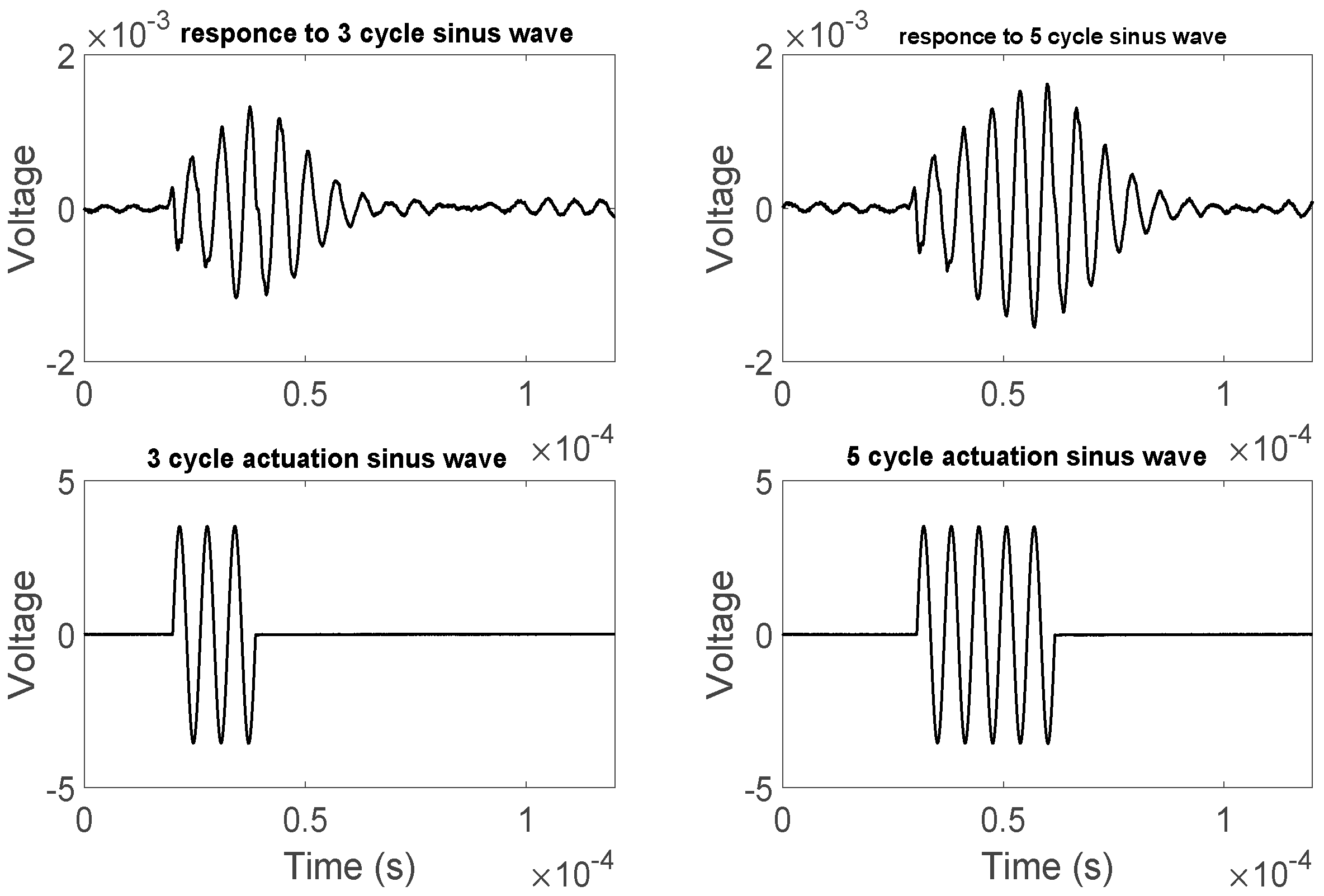
To demonstrate the time domain response of the communication between two transducers, two sinus pulses with 3 and 5 cycles respectively are exerted and responses are shown in Figure 3. The transient time is about 35 µs.
4. Conclusions
An omnidirectional ultrasound transducer was designed and fabricated by mean of two Si-SiC hemisphere shells, which are actuated by a single piezoelectric (PZT) element. The Si-SiC shells were fabricated by an additive manufacturing technique, namely selective laser sintering. All components were assembled utilizing two CircuitWork CW2400 and Epotek 353ND epoxies. The transducer was fully functional under water at its first resonance frequency (160 kHz) and has a circumferential pressure loss of maximum 10 dB.
Acknowledgments
This work was supported by the Research Foundation—Flanders (FWO) under project FWO-G.0956.14N, the research fund of KU Leuven through project GOA/15/012-SUMMA and the European Union’s Horizon 2020 research and innovation program under grant agreement No. 665347.
Conflicts of Interest
The authors declare no conflict of interest.
References
- Cannata, J.M.; Ritter, T.A.; Chen, W.H.; Silverman, R.H.; Shung, K.K. Design of efficient, broadband single-element (20–80 MHz) ultrasonic transducers for medical imaging applications. IEEE Trans. Ultrason. Ferroelectr. Freq. Control 2003, 50, 1548–1557. [Google Scholar] [CrossRef] [PubMed]
- Sun, P.; Wang, G.; Wu, D.; Zhu, B.; Hu, C.; Liu, C.; Djuth, F.T.; Zhou, Q.; Shung, K.K. High frequency PMN-PT 1–3 composite transducer for ultrasonic imaging application. Ferroelectrics 2010, 408, 120–128. [Google Scholar] [CrossRef] [PubMed]
- Dausch, D.E.; Gilchrist, K.H.; Carlson, J.B.; Hall, S.D.; Castellucci, J.B.; von Ramm, O.T. In vivo real-time 3-D intracardiac echo using PMUT arrays. IEEE Trans. Ultrason. Ferroelectr. Freq. Control 2014, 61, 1754–1764. [Google Scholar] [CrossRef] [PubMed]
- Lee, S.K.; Mace, B.R.; Brennan, M.J. In-plane free vibration of curved beams. In Proceedings of the 15th International Conference on Sound and Vibration, Daejeon, Korea, 6–10 July 2008; pp. 2091–3098. [Google Scholar]
- Kruth, J.P.; Levy, G.; Klocke, F.; Childs, T. Consolidation phenomena in laser and powder-bed based layered manufacturing. CIRP Ann. Manuf. Technol. 2007, 56, 730–759. [Google Scholar] [CrossRef]
Figure 1.
(a) The structure of the transducer before (I) and after (II) assembly.; (b) Microstructure of the produced material, with Si (light grey matrix) and α-SiC (dark grey grains).
Figure 1.
(a) The structure of the transducer before (I) and after (II) assembly.; (b) Microstructure of the produced material, with Si (light grey matrix) and α-SiC (dark grey grains).

Figure 2.
(a) FEM simulation and measurement of the frequency response of the transducer; (b) (I) The measured receiving frequency response of the transducer in communication with another transducer and (II) the beam pattern of the transducer, measured in the perpendicular plane to the surface of the piezoelectric elements.

Figure 3.
The pulse response of the transducer to a 3 and 5 cycles sinus waves.


Table 1.
Properties of fabricated Si-SiC material and pure SiC.
| Material | SiC (vol %) | ||
|---|---|---|---|
| Si-SiC | 2.57 | 220 | 35 |
| SiC | 3.21 | 450 | 100 |
Publisher’s Note: MDPI stays neutral with regard to jurisdictional claims in published maps and institutional affiliations. |
© 2017 by the authors. Licensee MDPI, Basel, Switzerland. This article is an open access article distributed under the terms and conditions of the Creative Commons Attribution (CC BY) license (https://creativecommons.org/licenses/by/4.0/).
Share and Cite
MDPI and ACS Style
Sadeghpour, S.; Meyers, S.; Kruth, J.-P.; Vleugels, J.; Puers, R. Single-Element Omnidirectional Piezoelectric Ultrasound Transducer for under Water Communication. Proceedings 2017, 1, 363. https://doi.org/10.3390/proceedings1040363
AMA Style
Sadeghpour S, Meyers S, Kruth J-P, Vleugels J, Puers R. Single-Element Omnidirectional Piezoelectric Ultrasound Transducer for under Water Communication. Proceedings. 2017; 1(4):363. https://doi.org/10.3390/proceedings1040363
Chicago/Turabian StyleSadeghpour, Sina, Sebastian Meyers, Jean-Pierre Kruth, Jef Vleugels, and Robert Puers. 2017. "Single-Element Omnidirectional Piezoelectric Ultrasound Transducer for under Water Communication" Proceedings 1, no. 4: 363. https://doi.org/10.3390/proceedings1040363