1. Introduction
In many engineering components that are subjected to dynamic loads it is of paramount importance to analyze the dynamic structural response to avoid dynamic problems such as resonances or fatigue that can drastically reduce their useful life. For this purpose, the technique known as Modal Analysis has been widely used in the past [
1,
2,
3,
4]. In Experimental Modal Analysis one of the first steps is to determine the Frequency Response Function (FRF), which means to determine the relation between response of the structure (in terms of vibration) and the dynamic force, for the frequency range of interest. Therefore, with the FRF the dynamic response of the structure can be analyzed around the resonance conditions.
One of the keypoints when performing Modal Analysis is the selection of the exciters that have to be used to determine the FRF. These have to be capable to excite the structure in the desired frequency range and they have to not affect the tested structure when they are used (load mass effect [
5]). Furthermore the sensitivity of the sensors, i.e., relationship between electrical and mechanical signal, has to be known. The most used actuators for Modal Analysis are instrumented hammers (no fixed excitation device) and different kind of shakers that can be fixed or not to the structure. In both cases, generally the sensitivity of the transducer and therefore the force that is being applied to the tested structure is known. Nevertheless, for some kind of inaccessible structures (such as confined and/or submerged structures) the use of these classical exciters can be very difficult due to the inaccessibility of the structure in operating conditions. For this kind of structures, exciters such as piezoelectric patches (PZT-patches) have been used in the past [
6,
7,
8,
9]. These studies show that natural frequencies, which are one of the structural parameters that define the FRF, can be determined by using PZTs. Nevertheless the FRF and the rest of associated parameters have not been determined by using this kind of transducers. This could be because the sensitivity of the transducer (relation between voltage and dynamic force) is not directly given by the manufacturers and it is well known that is not linear in all the frequency range.
This paper has the objective to analyze how PZT-patches can be used to determine all the modal characteristics (natural frequencies, mode shapes, damping and scaling factors) that define the complete FRF of a structure. For this purpose the FRF of a tested structure is determined with a classical excitation method (instrumented hammer) and compared with the response obtained with a PZT-patch excitation. In this way it is shown how to extract modal parameters when using PZTs. Finally, the advantages of using PZT exciters to determine the FRF of inaccessible structures are evaluated testing the same structure submerged in water.
2. Modal Analysis Model
The basic assumption of the modal analysis is that each structure can be understood as a superposition of masses, springs and dampers interconnected to each other. The matritial equation that express this model is typically written as [
1,
2]:
,
are respectively the displacement, velocity and acceleration vector in the discretized points.
are respectively the matrices of mass, dampers and springs. In order to estimate the modal parameters that define the dynamic response of the structure the Frequency Response Function (FRF) has to be obtained. This is defined as the relationship between displacement and force in the frequency domain (
:
The FRF (
of a proportionally damped system (which is a common model for damping) can be expressed as:
Each structure has infinite vibration modes but with the discretization used in modal analysis just N of them are obtained. Equation (3) express the FRF as the superposition of parameters that define each mode r:
Natural frequency: is the natural frequency of the corresponding mode r
Damping: is the damping factor. Damping determines the amplitude of the structural response when the system is close to a resonance condition
Mode shapes: define the deformation of the structure close to resonance condition
Scaling factor: for each mode r
Due to the definition of , these parameters can be also obtained experimentally by measuring simultaneously and with appropriate transducers.
is tipically obtained with a motion sensor such as an accelerometer (fixed to the structure) or with a non contact sensor (proximity probe, Laser Doppler Vibrometer…). has to be measured with a calibrated actuator, i.e., sensitivity of the sensor in force (V/N), has to be known. With classical exciters such as an instrumented hammer or shakers this parameter is known and given by the manufacturer. For PZT-patches this information is not directly given by the manufacturers and according to the authors knowledge this has not been successfully obtained in the past.
3. Experimental Set-Up
The use of PZT-patches as exciters in Modal Analysis has been tested in a structure consisting of a circular disk hanged with a thin rope. The structure has been also excited with a calibrated Hammer in order to have a reference FRF.
3.1. Equipment Used
3.1.1. Tested Structure
It is a stainless steel disk with 200 mm diameter. The total mass of the disk is approximately 7.6 kg.
3.1.2. PZT-Patch
The patch used for this test is the PI-876-A12. This has been glued on the disk with an epoxy component (LOCTITE 9466).
3.1.3. Signal Generator and Amplifier
The electrical signal sent to the patch is generated with the module NI-9263 and conditioned to the PZT voltage range (−100 V to 250 V) with an amplifier OEM 835.
3.1.4. Instrumented Hammer
The hammer used to obtain the reference FRF is the instrumented hammer Dytran 9722A2000 with a sensitivity of 2 mV/N.
3.1.5. Accelerometer
To measure the structural response of the disk an accelerometer Dytran 3006A with a sensitivity of 100 mV/g has been used.
3.1.6. Acquisition System
All the signals have been acquired using a B&K LANXI 5023 module with 12 channels and maximum acquisition frequency of 66 kHz. All the equipment used can be seen in
Figure 1.
3.2. Excitation Charactersitic
A chirp signal of 8 s varying the frequency from 0–1000 Hz (linear variation) is used to excite the disk. The disk is excited 5 times in this way for averaging and calculation of the coherence [
2]. When using the impact hammer, the disk is hit 5 times on the middle of the patch but on the opposite side (
Figure 1).
3.3. Tests with the Disk Submerged
The same procedure as explained in the previous points is used to excite the disk submerged in water.
4. Results and Discussion
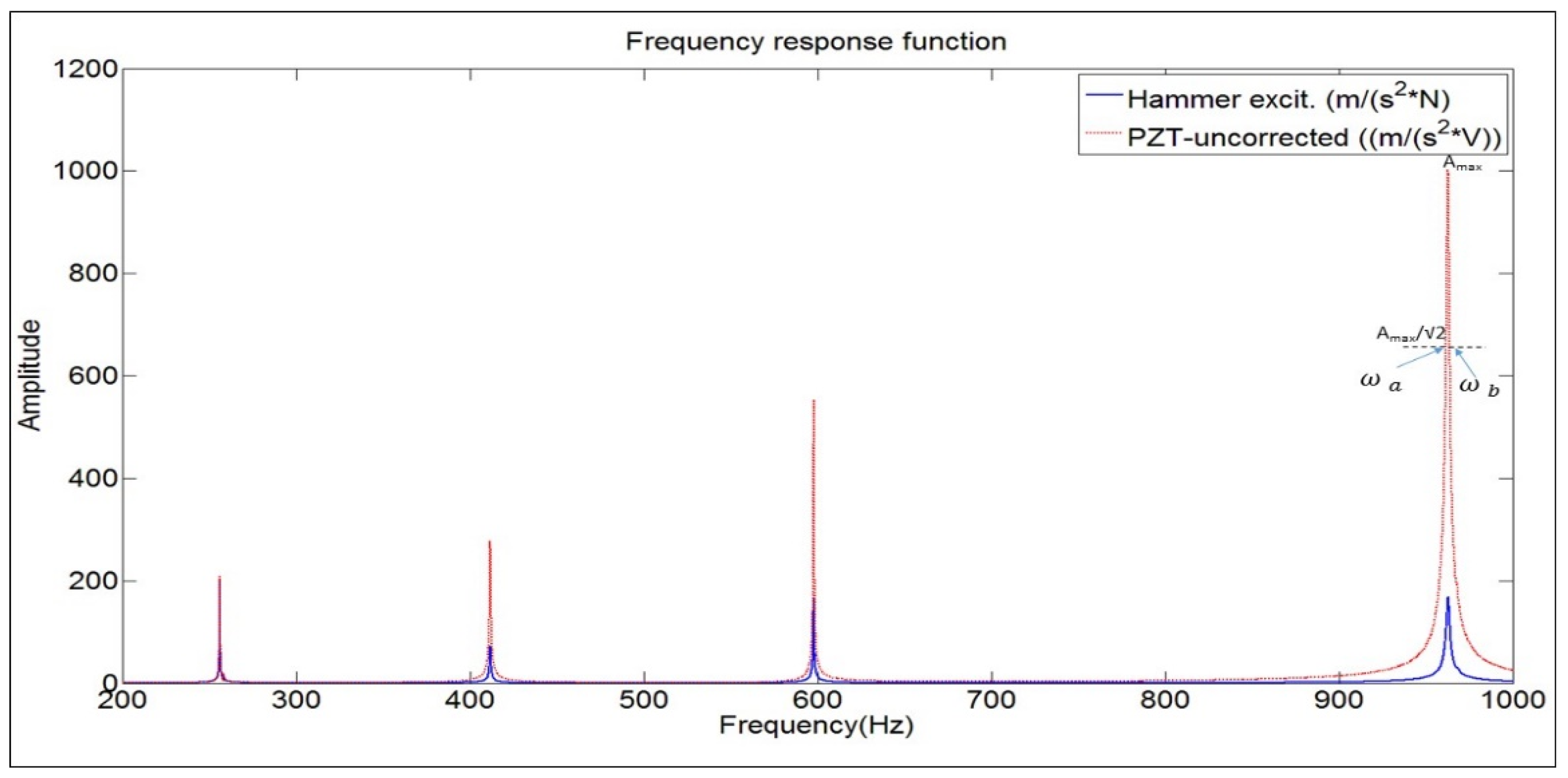
The FRF ((m/s
2)/N) is obtained with the impact hammer and compared with the relation voltage-force ((m/s
2)/V) that is obtained when using the PZT-patch (
Figure 2). Note that this second function is just the relation between the signal of the accelerometer and the excitation signal sent to the patch in the frequency domain (not the FRF). As mentioned before the relation voltage-dynamic force is not generally known for PZT-patches.
4.1. Natural Frequencies
The peaks shown in
Figure 2 are the analyzed natural frequencies (range 0–1 kHz) for the tested structure. The value of these natural frequencies obtained with both methods is shown in
Table 1. As in other studies [
6,
7,
8,
9], it is shown that when using PZTs the natural frequencies of the tested structure can be well determined. In case of very light structures, where the load mass effect of the actuator could affect the results [
5], the natural frequencies of the tested structure could be determined more precisely with PZTs than with the impact Hammer.
4.2. Damping
The damping ratio (
) is estimated with the classical half power method [
1,
2] applied on the peaks of the FRF. For each mode
r:
The values
determine the frequency band around
, where the amplitude of the FRF is
(see
Figure 2). From
Table 1, it can be seen that when using the same method for the peaks of the function obtained with the PZT ((m/s
2)/V) the damping ratio can be also determined. In fact, the damping ratio could be estimated with the same method also with the response only
(or autospectrum) if the force in the frequency band
would be constant (impact excitation). This means, that although the force of the patches varies with the frequency (easily deduced comparing the two curves in
Figure 2) it can be assumed that is approximately constant in the small frequencybands used for the damping estimation.
4.3. Mode Shapes
Since for
the motion of the structure is dominated by the mode shape [
1,
2] it can be easily demonstrated that both methods will give the same mode shape (also experimentally demonstrated in [
8]). The classical way to compare two modal vectors is with the MAC indicator [
1,
2]. In this case, the MAC has been obtained analyzing the mode shapes defined in 16 equidistant points on the periphery of the disk. The values close to 100% (
Table 1) show that the mode shapes obtained with the two methods are practically the same.
4.4. Scaling Factors
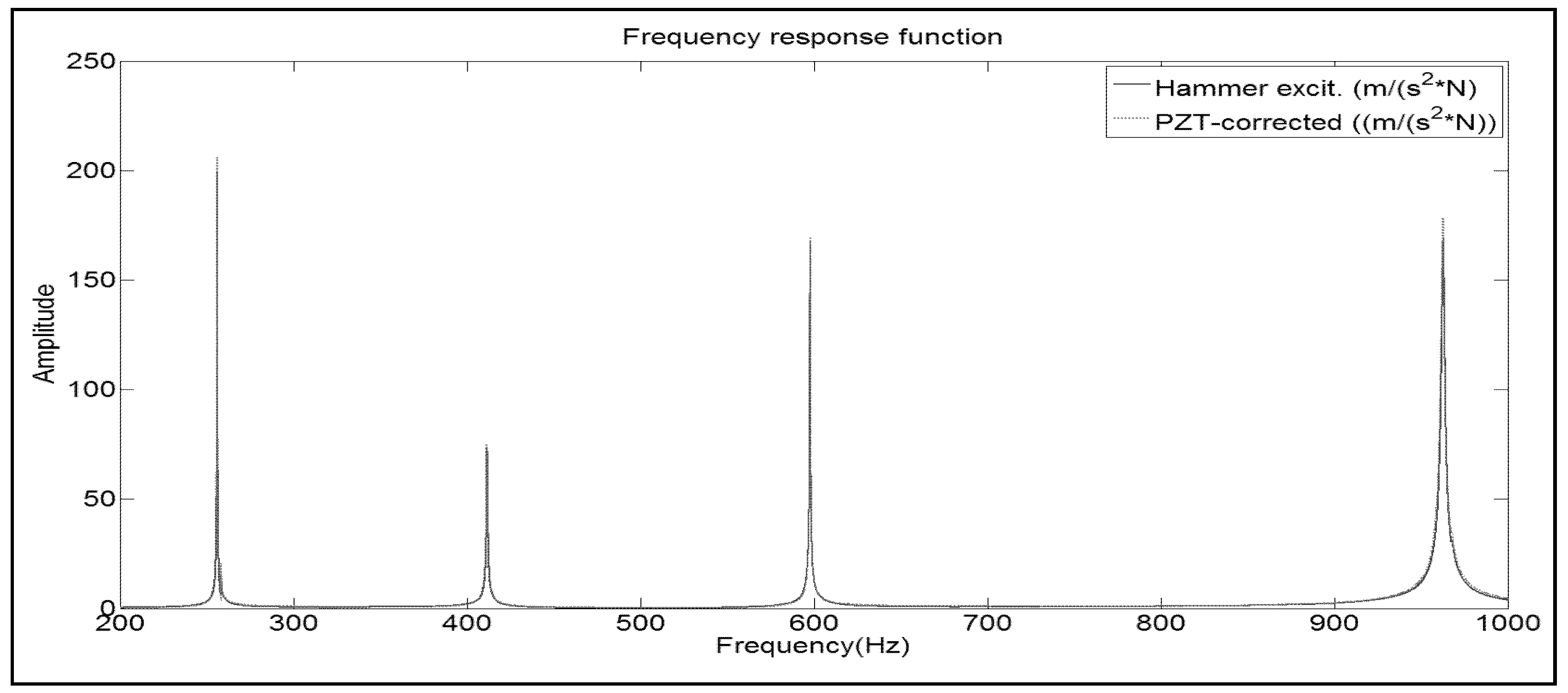
Looking at Equation (3), the only remaining modal parameter to determine the complete FRF when using the PZT-patch is the scaling factor
, which defines the real amplitude of the peaks for each mode
r. Note that for the estimation of all the previous modal parameters the calibration voltage/force of the PZT-patch was not necessary, as demonstrated experimentally in this paper (
Table 1). Nevertheless, to have the amplitude of the peaks it would be necessary to have such calibration, which is complicated to be obtained experimentally, as mentioned in previous sections.
For this reason and in order to obtain the true amplitude of the peaks in the FRF, the method proposed here is to combine the information obtained experimentally with the PZTs (natural frequencies & damping) and to use it in a computational Finite Element Model of the tested structure. For this kind of computational models the structure is generally modeled as an assembly of masses and springs but without considering the damping [
10] and therefore, the real amplitude of the FRF cannot be obtained. Nevertheless, the estimation of the real amplitude can be obtained if the experimental damping factor obtained experimentally, is introduced in the model.
For the current structure ANSYS v.16 was used. With Numerical Modal Analysis and without damping, it was checked that the natural frequencies obtained experimentally and numerically had a discrepancy of less than 2.5%. The next step was to introduce the damping obtained experimentally in the model (for every mode) and to perform the numerical analysis again (harmonic analysis). For this second analysis, the force was applied in the same point than the middle point of the patch and the response evaluated in the same position than the accelerometer (
Figure 1). In this way the real amplitude of the FRF is obtained by means of numerical simulation and therefore the scaling factors
can be calculated and the function ((m/s
2)/V) shown in
Figure 2 can be corrected according to these factors.
Figure 3 shows the comparison of the estimated FRF function when using the PZT (after correction with the numerical model) with the FRF (obtained with the Hammer).
It can be seen that now both functions have aproximately the same amplitude on the resonant peaks (discrepancy of less than 6%), which means that with the use of PZT, the real FRF can be well estimated.
4.5. Modal Parameters of the Structure Submerged in Water
For submerged and/or inaccesible structures it can be dificult to use clasical exciters due to the inaccesibility of the tested structure. Even if they could be used, the use of them can modify the boundary conditions of the test. In this case it is very advantageous to use PZT. Aplying the same procedure explained before, now the tested structure has being excited submerged in water and close to a rigid wall. Modal parameters are obtained for the Hammer excitation and for the PZT excitation (
Table 2).
As seen in this table, the experimental values of the frequencies are very close when comparing both methods but damping values are totally diferent. The reason for this diference is that when impacting the structure with the Hammer, the structure is slightly moving in the water affecting the velocity profile of the surrounding fluid and therefore affecting the fluid damping. This demonstrates, that for this kind of structures, the modal parameters can be better determined using PZTs.
5. Conclusions
In this paper, it has been shown how to use PZT patches as exciters in Experimental Modal Analysis (EMA) of a generic structure. This is particularly interesting, because these exciters, which are extremely light and thin, can be used for inaccessible structures (confined, rotating, submerged…) where other classical exciters used in EMA are almost impossible to be installed and can disturb the boundary conditions of the test.
For a tested structure, the excitation made with a PZT-patch has been compared with the excitation made with a classical method (calibrated Hammer). Results show, that when PZTs are used as exciters, most of the modal parameters, such as natural frequencies, mode shapes and damping, that define the Frequency Response Function (FRF) of the structure, are correctly obtained, without a previous calibration voltage/force of the PZT-patch.
In order to determine the Frequency Response Function (FRF) of the tested structure completely when using PZTs, this paper proposes a combined method, introducing modal parameters obtained experimentally in a numerical Finite Element Model.
Finally, the potentiality of PZTs patches as exciters of inaccessible structures has been proved using them in the same structure submerged. Results show that other classical exciters (Impact Hammer), typically used in Modal Analysis, disturb the boundary conditions making a wrong estimation of some of the modal parameters.


 ,
, 


