Article

Genetic Algorithm-Based Optimisation of a Double-Wall Effusion Cooling System for a High-Pressure Turbine Nozzle Guide Vane †

by
Michael van de Noort
* and
Peter T. Ireland
Department of Engineering Science, University of Oxford, Oxford OX1 3PJ, UK
*
Author to whom correspondence should be addressed.
This paper is an extended version of our paper published in Proceedings of the European Turbomachinery Conference ETC15 2023, Paper No. 202, Budapest, Hungary, 24–28 April 2023.
Int. J. Turbomach. Propuls. Power 2024, 9(1), 6; https://doi.org/10.3390/ijtpp9010006
Submission received: 25 July 2023 / Revised: 22 December 2023 / Accepted: 28 December 2023 / Published: 2 February 2024

Abstract

:
Double-Wall Effusion Cooling schemes present an opportunity for aeroengine designers to achieve high overall cooling effectiveness and convective cooling efficiency in High-Pressure Turbine blades with reduced coolant usage compared to conventional cooling technologies. This is accomplished by combining impingement, pin-fin and effusion cooling. Optimising these cooling schemes is crucial to ensuring that cooling is achieved sufficiently at high-heat-flux regions and not overused at low-heat-flux ones. Due to the high number of design variables employed in these systems, optimisation through the use of Computational Fluid Dynamics (CFD) simulations can be a computationally costly and time-consuming process. This study makes use of a Low-Order Flow Network Model (LOM), developed, validated and presented previously, which quickly assesses the pressure, temperature, mass flow and heat flow distributions through a Double-Wall Effusion Cooling scheme. Results generated by the LOM are used to rapidly produce an ideal cooling system design through the use of an Evolutionary Genetic Algorithm (GA) optimisation process. The objective is to minimise the coolant mass flow whilst maintaining acceptable metal cooling effectiveness around the external surface of the blade and ensuring that the Backflow Margin for all film holes is above a selected threshold. For comparison, a Genetic Aggregation model-based optimisation using CFD simulations in ANSYS Workbench is also conducted. Results for both the reduction of coolant mass flow and the total optimisation runtime are analysed alongside those from the LOM, demonstrating the benefit of rapid low-order solving techniques.

1. Introduction

This paper is an extended version of [1]. As the demand for improved aeroengine fuel efficiency has soared over recent decades, designers have pushed for increased Turbine Entry Temperatures which have produced greater values of thermal efficiency throughout the turbine. Today, TETs in modern aeroengines are well in excess of the softening temperatures of the nickel superalloys used to manufacture turbine components—this necessitates the use of cooling systems to keep component temperatures at safe values. To provide the high-pressure air required to effectively cool turbine components, compressed air is siphoned off from the compressor’s core flow. This means that less core flow passes through the combustor; limiting the power output of the engine [2] found that for every 5% of compressor air diverted for cooling, a 1% penalty in fuel burn was suffered. Coolant air must also be ejected from turbine components back into the mainstream flow, which creates mixing losses that reduce the turbine’s aerodynamic efficiency. As such, designers look to optimise cooling systems to use as little coolant as possible whilst meeting the required cooling performance.
One cooling scheme with great promise for tackling this problem is Double-Wall Effusion Cooling, which combines the commonly used cooling techniques of impingement cooling, pin-fin (pedestal) cooling, and film/effusion cooling. An example of it being employed in a blade is shown in Figure 1. The combination of these cooling techniques produces an overall system with high convective cooling efficiency η c o n v and overall cooling effectiveness ε o (1). Double-Wall Effusion Cooling is yet to be implemented in any commercial application to the author’s knowledge, despite having been researched since the 1970s. This has been primarily due to two factors—manufacturing difficulty, for which great progress has been made in the last decade or so, and high thermomechanical stresses due to the high temperature gradient across the pedestals—This issue has been the subject of extensive research in recent times (e.g., [3,4]).
η c o n v = T c , e T c , i T m , a v e T c , i ,     ε o = T T m , a v e T T c , i ,     B F M = P f , i n P f , e ,     M = ρ c , e U c , e ρ U
Additionally, the combination of three cooling techniques (particularly impingement) leads to high pressure losses through Double-Wall Effusion Cooling Schemes. These losses make said schemes susceptible to coolant migration—‘the movement of coolant in the pedestal cavity toward low pressure regions under the influence of an external pressure gradient’ [6]. The vulnerability is greatest for the High-Pressure NGV, where mainstream stagnation pressure is only ~3% less than that of the coolant supplied. This can have severe effects in multiple regions—high-pressure areas, such as the Leading Edge, will suffer a loss of coolant such that what remains is insufficient for effective external cooling. In extreme circumstances, high coolant migration can starve high-pressure regions of coolant, drastically reducing the Backflow Margin B F M (1) of film holes and risking hot gas ingestion. In low-pressure regions that the coolant migrates to, film holes can become oversupplied, raising the Blowing Ratio M (1) and causing jet lift-off, again reducing the external cooling performance.
This study makes use of the previously developed and validated LOM (see [6,7]) to examine how select geometric features can be optimised to minimise coolant mass flow through a High-Pressure Nozzle Guide Vane whilst maintaining acceptable cooling performance and ensuring that a minimum B F M is achieved for all effusion holes. Results from the LOM are used with MATLAB R2021b’s inbuilt Genetic Algorithm capability to give optimal diameters for 15 rows of impingement holes and 15 rows of effusion holes. For comparison, a study is conducted using a Genetic Aggregation-based optimisation with CFD results with the same objective.

2. Related Work

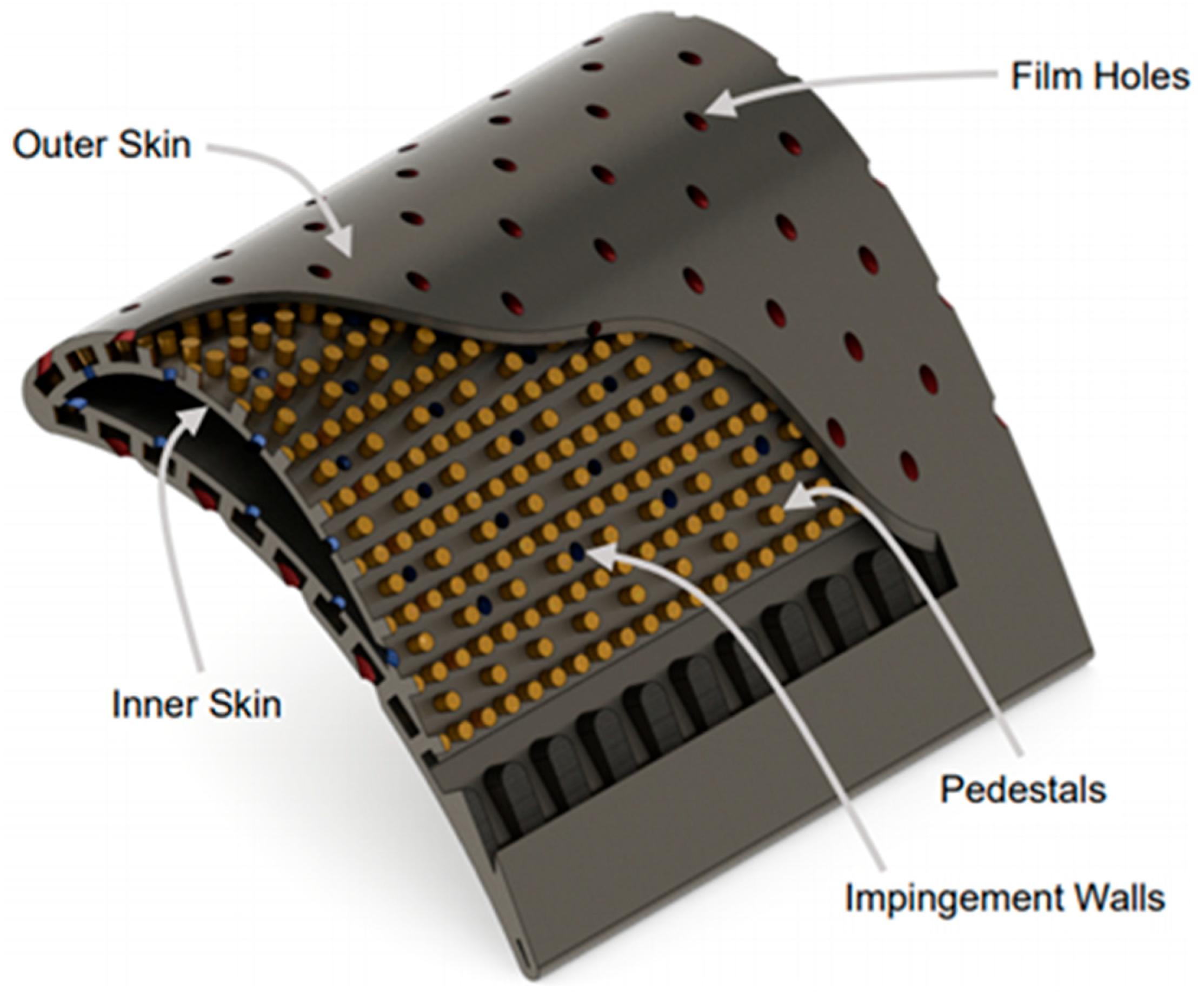
2.1. Double-Wall Effusion Cooling Systems

The three cooling systems that make up Double-Wall Effusion Cooling schemes are used in a large number of applications, so they have been the subjects of extensive research. The first, impingement cooling, is generally known to be the most ‘powerful’ in terms of cooling ability, which is governed by the impingement jet Reynolds number, the wall-spacing-to-hole-diameter ratio, and the impingement area. Numerous correlations for impingement Nusselt number have been developed, e.g., [8,9]. Impingement cooling also dominates the pressure losses when combined with other cooling systems, as was observed by Andrews et al. [10].
A similar conundrum plagues pedestal cooling, where higher HTCs are almost universally accompanied by higher pressure losses—this was demonstrated by Chyu et al. [11] where diamond-shaped pedestals were seen to have greater HTCs and friction factors when compared to cylinders.
Murray et al. [12] explained the difference between effusion cooling and film cooling as the use of low spacing and smaller holes to create a higher porosity skin, which has been seen to lead to exceptional film cooling performance [13]. Courtis et al. [14] used a flat plate experiment to demonstrate that reducing the spanwise spacing of effusion holes could lead to a greater increase in average film cooling effectiveness than reducing their streamwise spacing.
Courtis and Ireland [15] conducted an extensive computational study for high outer-skin porosity Double-Wall Effusion Cooling systems and noted that the higher effusion hole area meant that effusion in-hole cooling replaced impingement cooling as the most dominant internal cooling feature. The outer-skin porosity increases were seen to have three key benefits when compared to less porous designs: improved film effectiveness (and thus more uniform outer-skin temperatures), increased overall cooling effectiveness, and a reduced thermal gradient over the pedestals which would alleviate some thermomechanical stress. The authors noted that these benefits came at the cost of reduced B F M and a greater risk of hot gas ingestion at low coolant flow rates.
Combined impingement and effusion systems (without pedestals) are also often applied for Combustor Liner cooling. Jackowski et al. [16] experimentally investigated the performance of such a cooling system, varying the cavity height and longitudinal specimen alignments. In engine-representative conditions, total cooling effectiveness values of 90% were reached. Notably, the influence of the impingement cooling within this system was minor at best.

2.2. Flow Networks

The flow networks developed for this work were based on those first presented by Rose [17] and by Kutz and Speer [18]. In each, networks are made up of nodes, each representing a point in the flow or solid domains, and links, which represent the pathways over which mass or energy is transferred. Static pressure and temperature are evaluated at each node, allowing the calculation of fluxes between them along links—each link will have some inherent compliance which determines the mass or energy flux as a function of the pressure or temperature difference across it. To solve a network, conditions for mass flow continuity and energy conservation must be satisfied to a reasonable tolerance at each node.
Flow networks have been successfully applied to numerous aeroengine applications. Ebenhoch and Speer [19] applied flow network modelling to a multipass blade cooling system, a hypersonic vehicle nozzle, and coolant in a rotating HP blade, in each case achieving ‘sufficient’ accuracy. Jin et al. [20] constructed a flow network solver for the Trailing Edge of an HP Turbine Blade. The results of mass flow distributions showed how design choices could be changed to reduce the risk of hot gas ingestion.

2.3. Genetic Algorithm Optimisation

Genetic Algorithm Optimisation is a method of optimisation that looks to evoke the process of natural selection in biological evolution, as the best ‘traits’ in a subset of a population are allowed to survive and are passed on to the next generation, whilst disadvantageous traits in other subsets of the population lead to their ‘deaths’, and said traits are not passed on. GA Optimisation studies are relatively common in turbine cooling research. Muller et al. [21] used two evolutionary algorithms to optimise the film cooling performance of a blade, looking to minimise the total coolant mass flow whilst maintaining adequate cooling performance. An evaluation was carried out using a 2D CFD domain. Both algorithms gave similar results, showing that the objective could be better met by clustering film hole rows around the Leading Edge and evenly spacing them around the Suction Surface.
Johnson et al. [22] used a 2D RANS solver in concert with a Genetic Algorithm to optimise the Nozzle Guide Vane Mid-Span geometry for minimal heat load. Compared to the baseline results, the peak LE heat transfer was reduced by 15% and the SS transition was moved 24% closer to the TE for the optimised geometry. In a later study, the same group [23] used a 3D RANS solver and a genetic algorithm to optimise the film cooling array of an HP Turbine Vane’s PS. A higher number of design variables were used, such that 0.32 × 10 552 different geometries were possible. Of these, 1800 were tested, with an optimised solution being produced with reduced heat loads, maximum temperatures, and pressure losses compared to the baseline design.

3. Low-Order Modelling Methodology

As noted, the LOM used for this work was developed, validated and presented in two previous publications (see [6,7]), in which greater detail is available. A briefer summary is presented here for ease of reference. The LOM developed uses two flow networks operating in tandem, shown in Figure 2. For modelling a larger array, these networks are mirrored and extended.
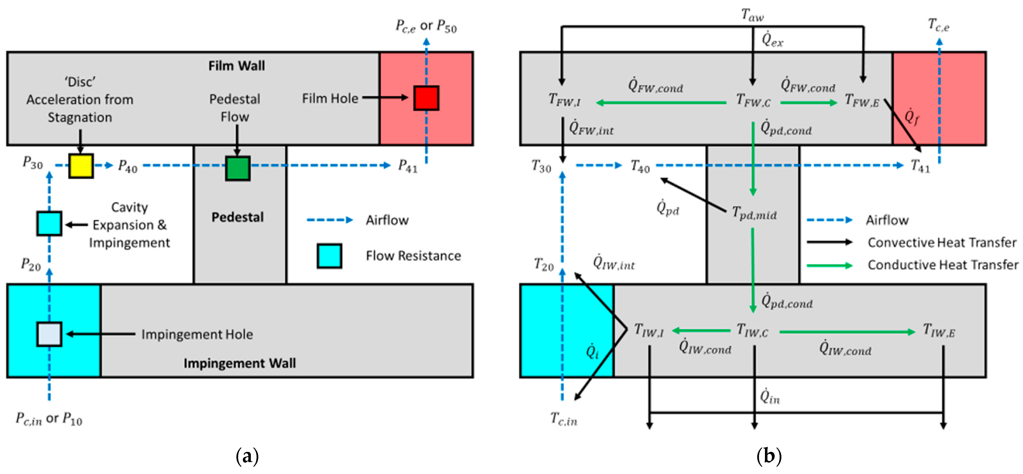
  • The Continuity Network solves for mass flow continuity through the fluid domain by evaluating static pressure at each node. The mass flow from inlet node i to outlet node j is dependent only on the pressure difference P i P j , the fluid density at inlet ρ i , and the link’s mass flow compliance C i , j .
  • The Energy Network solves for energy conservation throughout both the fluid and solid domains. For fluid nodes, this requires balancing flow enthalpy (dependent on the flow’s inlet temperature T i ) and heat transfer from the solid. The heat transfer from fluid node i to solid node k is dependent only on the temperature difference T k T i and the link’s heat transfer rate Q ˙ i , j .
The equations for mass flow rates in the continuity network are detailed in Table 1. Mass flows through the impingement holes (2) are found using a Discharge Coefficient equation developed by Mazzei et al. [24]. For film hole flows (6), a correction is made for mainstream crossflow based on the findings of Gritsch et al. [25]. The area ratios β i and β f were based on a large square inlet area, and the expansibility factor ε was unity. Flows around pedestals (5) are calculated using a friction factor developed by Wang (1991) and a loss coefficient associated with flow turning into the hole. Loss coefficients k l , e x and k l , i are used for mass flows in the cavity expansion (3) and acceleration from impingement flows (4), respectively. No flow Mach number exceeds 0.3, so all flows are taken as incompressible. Inlet and exit pressures P 10 and P 50 are used as boundary conditions.
For the energy network, the only boundary condition in the network is the coolant inlet temperature T c , i n —the coolant exit temperature T c , e is a free variable. Q ˙ i n and Q ˙ e x , with driving temperatures T i n and T a w , represent the transfer of heat to the coolant plenum and from the mainstream, respectively. Conductive heat transfer rates between nodes i and j in the solid are found using (7).
Q ˙ i , j = k s A i , j L i , j T i T j
Calculation of convective heat transfers required the use of empirical Nusselt number correlations from the literature. These are listed in Table 2—the characteristic length would be used to calculate the local heat transfer coefficient h , with which the heat transfer rate could be found. The impingement N u correlation chosen (8) was derived by San and Shiao [9], applicable for its low spacing-to-hole-diameter ratio. The correlation was related to the Nusselt numbers for heat transfer on both the internal (9) and external (13) surfaces of the impingement wall using factors found by Gillespie [26]. Cooling on the internal surfaces of both impingement (11) and film holes (10) was evaluated using the Dittus–Boelter correlation. The commonly used correlation for a cylinder in crossflow (12) was used for pedestal cooling. Finally, a correlation for flow over a flat plate from Howatson et al. [27] was used to model external heat transfer (14).
As each solid temperature node represents the centre of its feature, the conductive heat transfer which accompanied each convective heat transfer was accounted for using a dummy temperature T s . As the conductive and convective heat transfer must be equal along a single link, the total heat transfer rate from fluid node c to solid node m can be found from (15).
Q ˙ T = h T A T m T c = h c o n v A T S T c = h c o n d A T m T S   1 h T = 1 h c o n v + 1 h c o n d
Film cooling was implemented by altering each film wall node’s corresponding adiabatic wall temperature T a w , effectively changing the driving temperature for the external cooling. This was accomplished by predicting the local film cooling effectiveness using a Goldstein correlation [28] modified by Courtis et al. [14]. This is given in (16). The coefficients used were those found in the authors’ previous publication [7]. As this study includes the potential for films to overlap, the Sellers superposition method [29] was utilised. For a node receiving film cooling from n holes, the local film cooling effectiveness is found in (17). In the solid domain of the energy network, each position in the film wall received external heating from a square area, over which η f would vary. As such, an area-averaged film effectiveness (18) was used to find the adiabatic wall temperature.
η f = T T a w T T c , e = M u d f 8 α t x d f + x d e c a y e x p z d f c 1 2
η f = 1 i = 1 n 1 η f i
η f ¯ = 1 A z m i n z m a x x m i n x m a x η f x , z d x d z
For external boundary conditions, a 2D CFD run of the uncooled vane was used to give the external velocity and pressure distributions. The external HTC distribution was calculated using the Ambrok method [30] detailed by Kays and Crawford [31]. The coolant inlet pressure and temperature were 1.05 bar and 300 K, and the mainstream temperature was 375 K. Figure 3 shows example results of the LOM when converged, showing the coolant mass flow distribution in (a) and the surface metal cooling effectiveness (19) distribution in (b). A gap appears in the pedestal cavity flow network, as a wall was employed to prevent migration at the largest pressure gradient along the early SS. This model was developed to use Newton’s Method in MATLAB R2021b, with convergence when no absolute node imbalance (either in kg/s or W) exceeded 10−8.
η m = T T m , m a x T T c , i

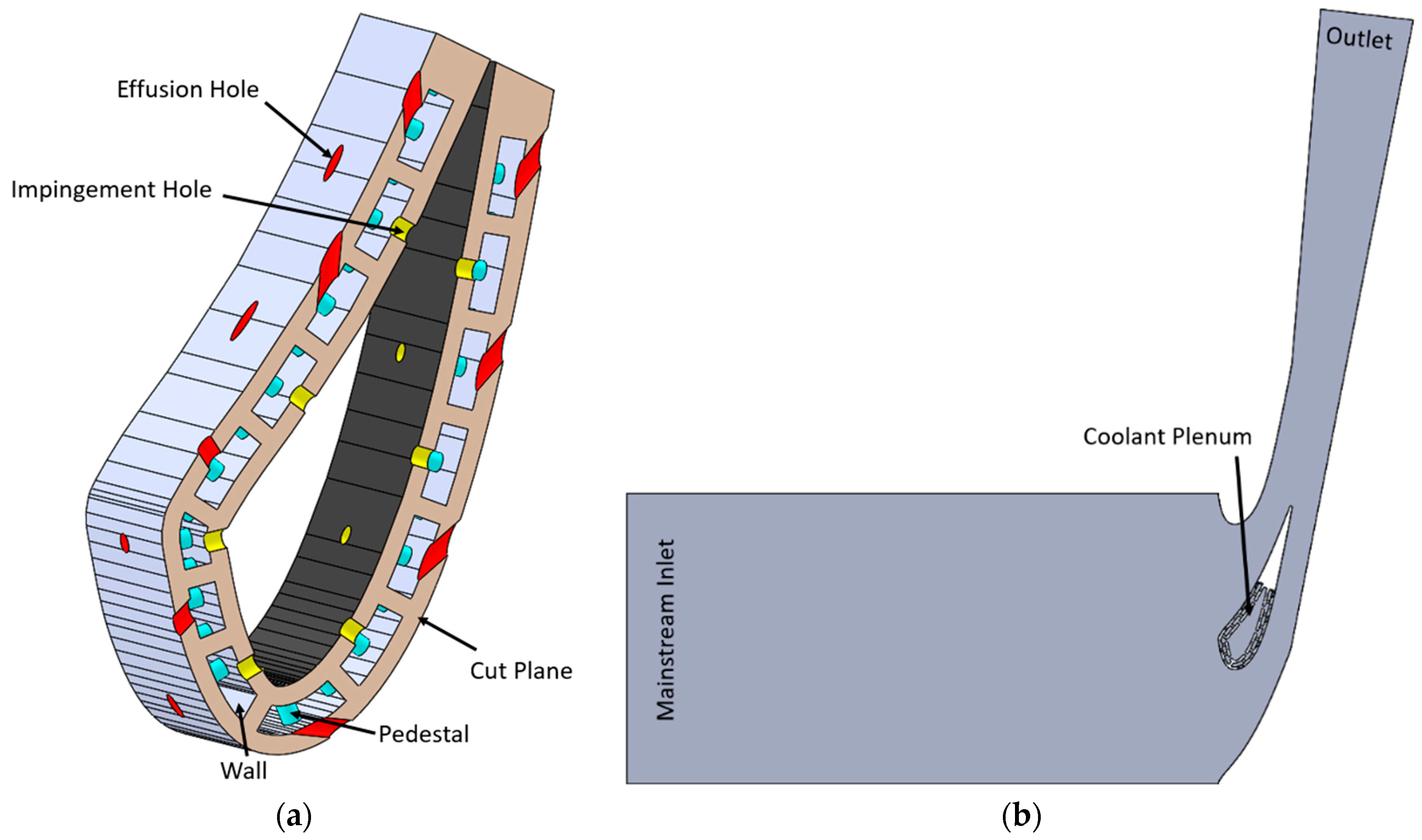
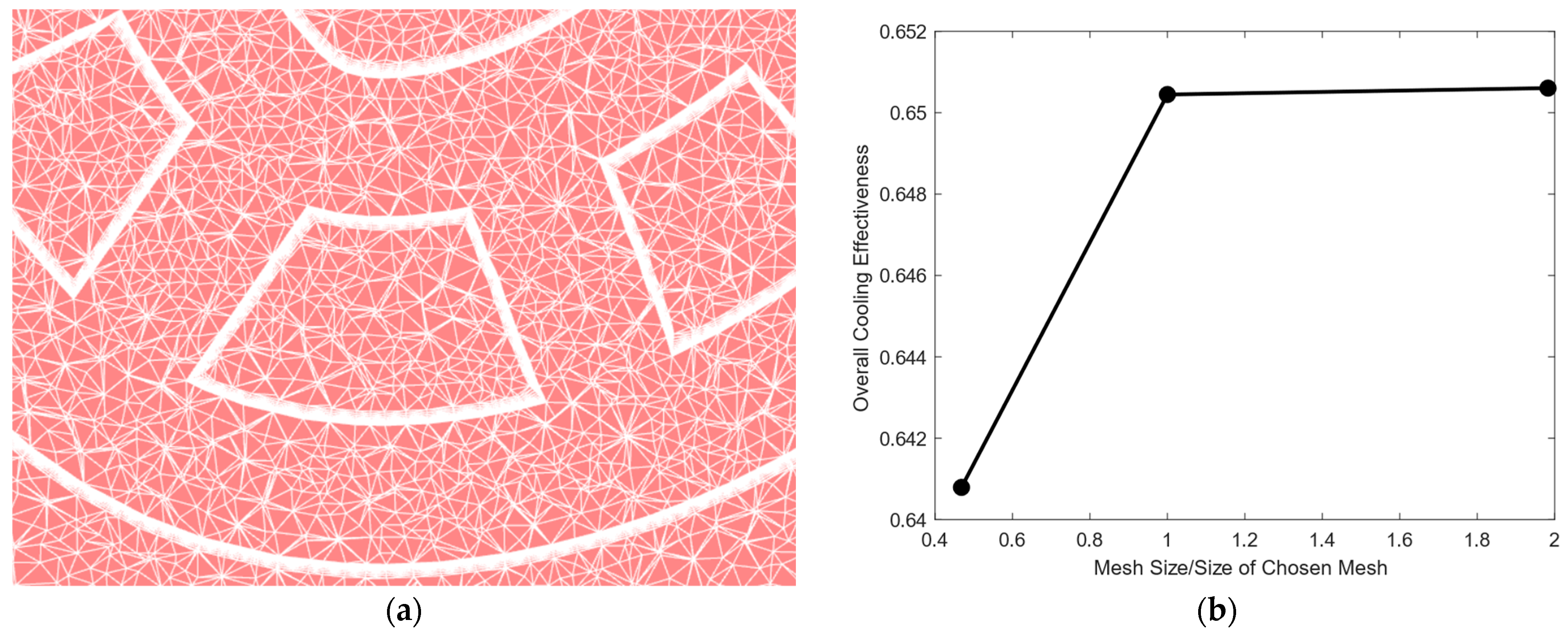
4. Computational Fluid Dynamics Methodology

CFD simulations for this study were conducted with ANSYS Fluent. The mainstream boundary conditions were matched to those of the 2D Simulation used to acquire the LOM’s external boundary conditions—an inlet pressure and temperature of 1.021 bar and 375 K, and an outlet pressure of 1 bar. These conditions produce a throat velocity of 100 m/s, matching the conditions from the study of Holgate et al. [32], from which the geometry was obtained. Coolant inlet conditions matched those of the LOM—an inlet pressure and temperature of 1.05 bar and 300 K. Convergence was assessed using default Fluent parameters. Simulations were conducted using the realizable k ε turbulence model with enhanced wall functions, as is the industry standard for tests of similar cooling geometries. The ideal gas law was used to set the coolant density, whilst all other fluid and solid properties were held constant at standard experimental conditions. This was necessary to ensure that flow conditions at the vane surface matched those of the 2D simulation and consequently ensured that the CFD Vane and LOM Vane were operating in the same conditions. The baseline computational domain for the solid is shown in Figure 4a (a cut section is made to show the internal cooling features) and the fluid in Figure 4b, which included the mainstream to allow external cooling. As for the LOM, the Trailing Edge of the solid is removed as TE cooling is beyond the scope of this study. The wall in the pedestal cavity is also replicated.
The mesh, predominately made of tetrahedral elements, was produced with inflation prism layers (15 layers at a growth rate of 1.2, set to a total thickness of 10% of the baseline hole diameter) along all surfaces other than film hole walls, where the local mesh was instead heavily refined—this ensured a y+ of below 2 on all non-film hole surfaces and below 5 on film hole surfaces. A view of the mesh, taken at the mid-plane at the early SS, is provided in Figure 5a. The results of the mesh independence study, based on the overall cooling effectiveness, are shown in Figure 5b. The final mesh contained ~9.5 million elements.

5. Optimisation Objective and Methodology

The objective of this optimisation study was the same for both methodologies:
  • Minimise Total Coolant Mass Flow m ˙ c .
  • Ensure Minimum Metal Cooling Effectiveness η m (19) of 0.44.
  • Ensure a B F M (1) of at least 1.0015 for each film hole.
If a test geometry failed to meet either of criterion 2 or 3, the design would be judged as a failure. The design variables chosen were the impingement and film hole diameters on each row around the vane—for 15 rows, this gave 30 design variables. All other geometric features—hole positions and inclinations, pedestal sizes, wall thicknesses etc.—were held constant. Hole diameters were allowed to vary by ±20% from the engine-representative baseline value.
For the LOM, optimisation was conducted using MATLAB R2021b’s inbuilt ga (Genetic Algorithm) function [33]. Each generation had 70 children, with 3 elite children, 49 crossover children and 18 mutated children. Convergence of the optimisation algorithm was achieved when the change in best fitness function value was less than 10−6 over 20 generations, running up to 350 generations. For CFD, the optimisation was carried out using ANSYS 19.2 Workbench’s inbuilt response surface optimisation. Genetic Aggregation was selected as the algorithm for response surface calculation, created using 70 samples which were selected using Latin Hypercube Sampling. Genetic Aggregation is a method based on a weighted average of different meta-models: Kriging, 2nd-Order Polynomial, Non-Parametric Regression and Moving Least Squares (see [34]). A Genetic Algorithm was subsequently used to find the optimum geometry from the response surface, reaching a convergence stability of 0.5% after evaluating 46 generations of 4000 samples each.

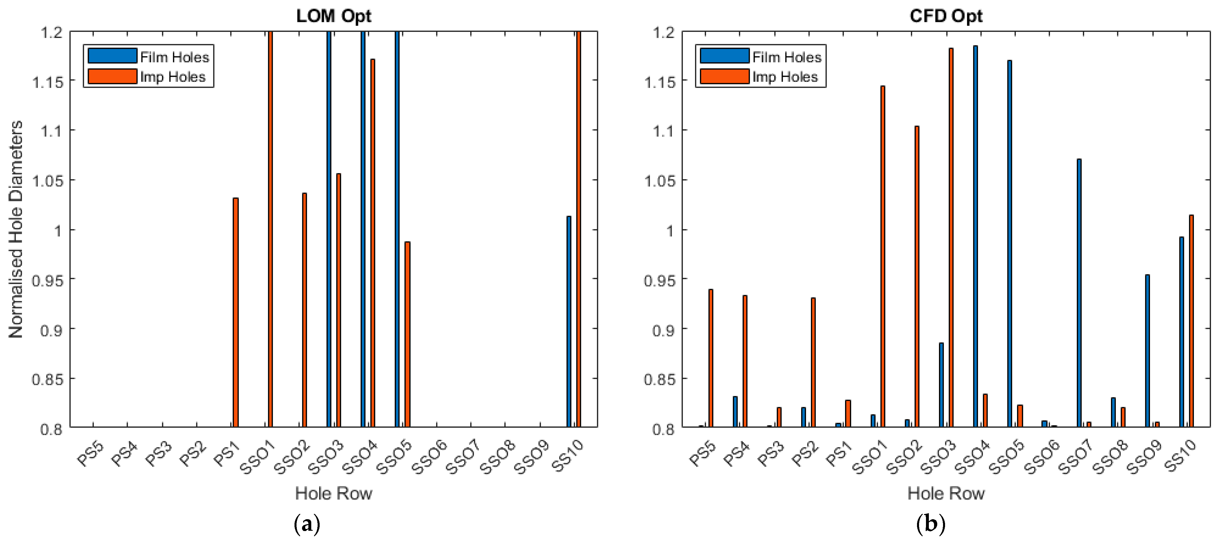
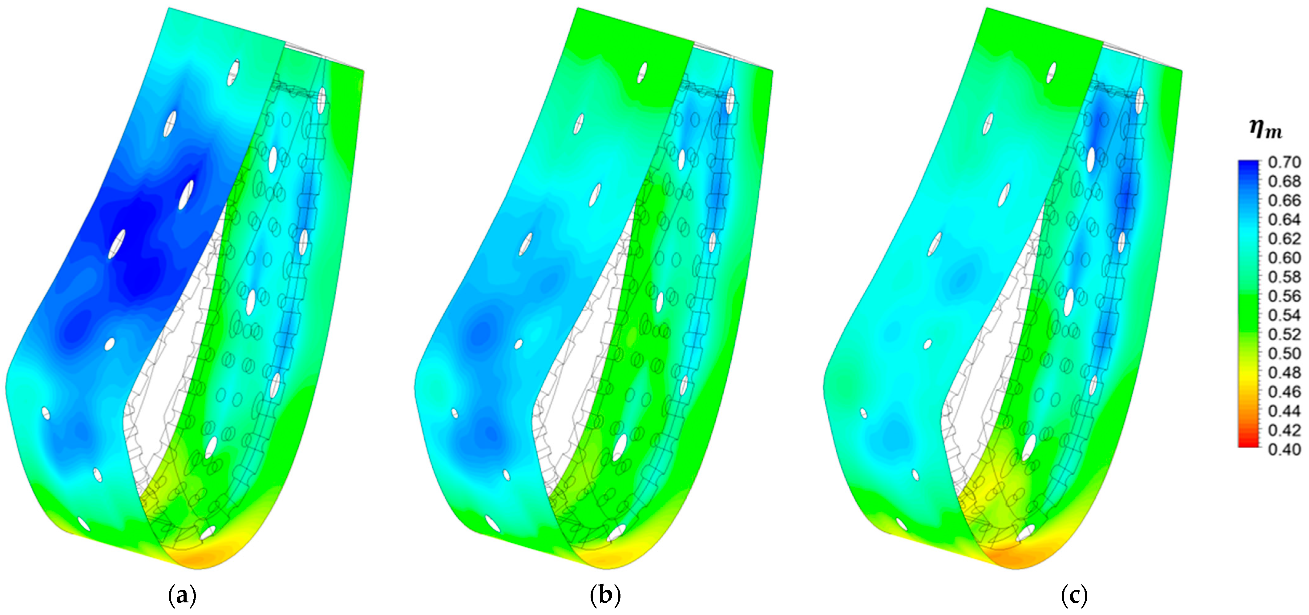
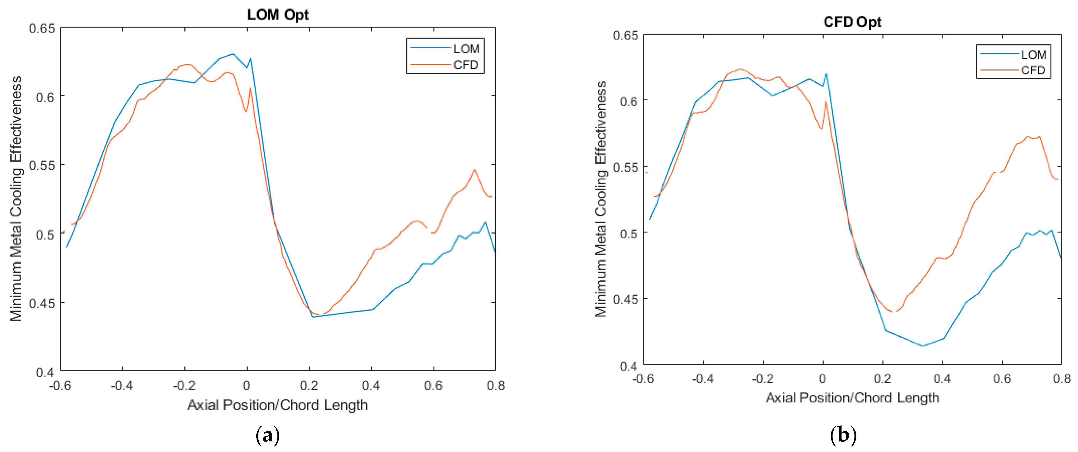
6. Results and Discussion

Figure 6 shows the results of the two different optimisation study methods in terms of how the film and impingement hole diameters were scaled, and Table 3 lists the objective function results for the baseline geometry, all minimised and all maximised hole sizes, and for both optimised geometries evaluated using both methodologies. Each geometry is the same for both the LOM and CFD.
Analysis of the LOM-GA method’s solution geometry can be broken up into 4 sections. Firstly, on the mid-to-late PS (PS5-2), the heat load is low, and the external pressure is not high enough to warrant any backflow concerns; thus, the local η m and B F M targets can be accomplished whilst minimising hole sizes to reduce the mass flow. Around the LE (PS1-SS02), the primary concern is maintaining the B F M for the film hole at SS01, requiring large impingement holes and small film holes to produce a large pressure ratio across the outer skin. As this film hole is fed by its three nearest impingement holes, all three must be enlarged to reduce pressure losses from jet impingement. Around the early SS (SS03-05), the heat load is at its greatest, requiring a high amount of coolant to meet the cooling criteria. As such, both the impingement and film holes in this region are maximised in size. The large amount of coolant used in this region also provides ample film cooling to the mid-SS (SS06-09). This film cooling, in addition to the drop in heat load, means that hole sizes can again be reduced to minimise local coolant usage. Finally, the last hole position SS10 requires larger hole sizes and high coolant levels to prevent the edges of the vane from overheating—this is a product of not including TE cooling. The total mass flow was reduced by 13.3% from the baseline. This geometry meets all the criteria in CFD, but the higher η m and B F M indicate that coolant usage could be further reduced in this method.
The CFD-Genetic Aggregation geometry generally follows the same design principles as the LOM-GA process’ optimal geometry, but due to higher predictions of local cooling effectiveness and B F M , it is able to exploit a lower mass flow (21.4% lower than the baseline). As with the LOM’s design, a low film-wall-to-impingement-wall porosity ratio is required at SS01 and SS02 to maintain an acceptable B F M at the LE. This is not applied to PS1 as in the LOM—this is due to coolant from PS1 moving exclusively toward PS2 in CFD, which does not occur in the LOM. The CFD approach is shown to require more cooling along the PS, with non-minimal impingement hole diameters at PS5, PS4 and PS2. The early SS (SS03-5) shows similarity with the LOM, requiring high cooling with large features. Cooling across the mid and late sections of the SS are more spread out, unlike the concentration of cooling features at SS10 shown in the LOM. As the LOM expects lower local cooling effectiveness, the CFD-optimised geometry does not meet the η m criteria when tested with the LOM.
The effects of the optimisation procedure are demonstrated in Figure 7, which compares the metal cooling effectiveness distributions for the baseline and the two optimised geometries, evaluated in CFD. The baseline geometry has significant overcooling along the main section of the Pressure Surface—both optimisation procedures sought to reduce this by minimising nearly all the hole diameters in the region, allowing a large amount of coolant mass flow to be saved. As noted previously, the LOM predicted a higher risk of hot gas ingestion and thus required larger impingement hole diameters around the LE, including at position PS1, leading to its optimised vane producing overcooling at the early PS compared to the CFD-Genetic Aggregation Optimised Vane. In contrast, the high hole diameters along the mid-to-late SS of the CFD-Genetic Aggregation Optimised Vane led to overcooling in this region compared to a more even distribution for the LOM-GA optimised vane.
Figure 8 shows how the two optimised geometries compare when tested using each method. For both the LOM-GA optimised geometry (Figure 8a) and the CFD-Genetic Aggregation optimised geometry (Figure 8b), the CFD tests show far more effective cooling along the Suction Surface, most likely due to higher predictions of film cooling effectiveness. This is best shown for the LOM-GA optimised geometry, where the mid-SS cooling feature sizes are minimal, as the cooling effectiveness climbs at a much higher rate for the CFD. For the CFD-optimised geometry, the LOM predicts the cooling effectiveness to continue to drop off toward Suction Surface position SS05. The CFD-optimised geometry relies on external effusion cooling far more than internal impingement cooling in this region, again leading to a disagreement between the two methodologies. Along the Pressure Surface, where low mainstream flow speeds increase the Blowing Ratio of effusion hole jets, the effect of external cooling is less prominent. This leads to far greater agreement between the LOM and CFD in this region.
To further investigate the difference in external cooling performance between the two methods, the CFD-Genetic Aggregation Optimised Vane was tested using both methodologies using a low-conductivity solid material ( k = 0.032   W / m K ), effectively neutering the effect of any internal cooling. This permitted the external wall temperature to be approximated as the adiabatic wall temperature, allowing the calculation of the external film cooling effectiveness using (15). The resulting film effectiveness contours are shown in Figure 9. In CFD, there is distinctly more lateral spreading of films, allowing a far greater build-up of the films along the Suction Surface compared to the LOM. For the LOM, positions at the edge of the vane received no external cooling whatsoever—in CFD, it was observed that greater reattachment of films from near the LE occurred whilst being spread out, leading to greater film cooling effectiveness around the edge of the early Suction Surface. This is shown in the streamlines of Figure 10, which tracks the coolant ejected from positions PS1 and SS01 in the CFD case. Streamlines of coolant ejected from SS01 show partial reattachment around the convex surface of the early SS, which was not the case for the LOM. In both cases, complete film detachment was predicted for coolant ejected from PS1.
The LOM-GA process used all 14 cores of a PC with a 2.5 GHz Intel Processor, allowing 14 test cases to be solved simultaneously. The entire LOM-GA process, which was completed in 48 generations (testing 3360 geometries), took nearly 11 h to complete, including a minimal amount of time for the genetic algorithm. For comparison, the CFD- Genetic Aggregation process used all cores of the same PC to solve each case, requiring them to be solved in turn—in total, this process took approximately 13 days of computational time, with an additional hour or so required to calculate the response surfaces and find the optimal geometry. Overall, this took ~30 times longer than the LOM-GA method. This time reduction makes a clear case for the use of the LOM-GA optimisation as a preliminary design tool for turbine cooling systems.

7. Conclusions

An experimentally validated Low-Order Flow Network Model has been presented for predicting the distributions of pressure, temperature, mass flows and heat flows throughout the fluid and solid domains of a High-Pressure Nozzle Guide Vane. This LOM has been used with a Genetic Algorithm to optimise the impingement and effusion hole diameters of an NGV’s Double-Wall Effusion Cooling System, reducing the coolant mass flow rate by 13% from the baseline value whilst achieving acceptable Metal Cooling Effectiveness and Backflow Margin for all effusion holes. For comparison, a CFD-based Genetic Aggregation optimisation was conducted for the same case study. The general designs of the two geometries were similar, showing regions where hole sizes could be minimised and those where larger features were required to produce sufficient cooling. The LOM’s optimised geometry, however, was produced 30 times faster than the CFD method. This difference in time taken for the optimisation studies to be completed highlights the advantage of a low-order approach in preliminary design stages in gas turbine cooling. In future, there is a possibility for this tool to be extended from serving as a design tool to serving as a diagnostic one. It is estimated that components manufactured at engine scale can have hole size deviations of ±10% [35], which could severely impact the cooling performance, as seen in this study. A LOM approach would allow rapid assessment of all possible deviations to determine the true nature of a part’s difference from its design.

Author Contributions

M.v.d.N. and P.T.I. established the goals of the work. M.v.d.N. carried out the Low-Order Model and CFD testing under the supervision of P.T.I. All authors have read and agreed to the published version of the manuscript.

Funding

This work is funded by Rolls Royce plc. and the EPSRC, under the CDT in Gas Turbine Aerodynamics (No. EP/L015943/1) and the Transpiration Cooling Systems for Jet Engine Turbines and Hypersonic Flight Programme Grant (No. EP/P000878/1).

Data Availability Statement

Data are contained within the article.

Acknowledgments

The authors wish to personally thank Janendra Telisinghe of Rolls Royce plc. for his oversight of this study.

Conflicts of Interest

The funders had no role in the design of the study; in the collection, analyses, or interpretation of data; in the writing of the manuscript; or in the decision to publish the results.

Nomenclature

A Area m 2
B F M Backflow Pressure Margin
c 1 Lateral Film Cooling Decay Factor
C d Discharge Coefficient
C F c o r r Cross-Flow Correction Factor
d Diameter m
f Friction Factor
h Heat Transfer Coefficient W / m 2 K
H Height m
k Thermal Conductivity W / m K
k l Pressure Loss Coefficient
L Length m
L E Leading Edge
m ˙ Mass Flow Rate k g / s
M Blowing Ratio
N u Nusselt Number
N G V Nozzle Guide Vane
P Pressure P a
P S Pressure Surface
P r Prandtl Number
Q ˙ Heat Transfer Rate W
R Radius m
R e Reynolds Number
S S Suction Surface
T Temperature K
T E Trailing Edge
T E T Turbine Entry Temperature
U Velocity m / s
x Streamwise Distance m
x d e c a y Film Cooling Streamwise Decay Factor
z Spanwise Distance m
α t Turbulent Thermal Diffusivity m 2 / s
β Area Ratio
ε Expansibility Factor
ε o Overall Cooling Effectiveness
η Effectiveness or Efficiency
ρ Density k g / m 3
Subscripts
0 Total
a v e Average
a w Adiabatic Wall
c Coolant
c o n d Conductive
c o n v Convective
e   o r   E Exit
e x Exterior
f Film/Effusion
F W Film/Effusion Wall
h Hydraulic
i Impingement
I W Impingement Wall
i n Inlet
i n t Interior
m Metal
m a x Maximum
m i n Minimum
p d Pedestal
s Surface
t Turning
Mainstream

References

  1. van de Noort, M.; Ireland, P.T. Genetic Algorithm Based Optimisation of a Double-Wall Effusion Cooling System for a High-Pressure Turbine Nozzle Guide Vane. In Proceedings of the 15th European Conference on Turbomachinery Fluid Dynamics & Thermodynamics, Budapest, Hungary, 24–28 April 2023. [Google Scholar]
  2. Thurman, D.; Poinsatte, P.; Ameri, A.; Culley, D.; Raghu, S.; Shyam, V. Investigation of Spiral and Sweeping Holes. J. Turbomach. 2016, 138, 091007. [Google Scholar] [CrossRef] [PubMed]
  3. Elmukashfi, E.; Murray, A.V.; Ireland, P.T.; Cocks, A.C.F. Analysis of the Thermomechanical Stresses in Double-Wall Effusion Cooled Systems. J. Turbomach. 2019, 142, 051002. [Google Scholar] [CrossRef]
  4. Skamniotis, C.; Courtis, M.; Cocks, A.C. Multiscale analysis of thermomechanical stresses in double wall transpiration cooling systems for gas turbine blades. Int. J. Mech. Sci. 2021, 207, 106657. [Google Scholar] [CrossRef]
  5. AMurray, A.V.; Ireland, P.T.; Rawlinson, A.J. An Integrated Conjugate Computational Approach for Evaluating the Aerothermal and Thermomechanical Performance of Double-Wall Effusion Cooled Systems. In Proceedings of the ASME Turbo Expo 2017, Turbomachinery Technical Conference and Exposition, Charlotte, NC, USA, 26–30 June 2017. [Google Scholar]
  6. van de Noort, M.; Ireland, P. A Low Order Flow Network Model for Double-Wall Effusion Cooling Systems. Int. J. Turbomach. Propuls. Power 2022, 7, 5. [Google Scholar] [CrossRef]
  7. van de Noort, M.; Murray, A.V.; Ireland, P.T. Low Order Heat & Mass Flow Network Modelling for Quasi-Transpiration Cooling Systems. In Proceedings of the ASME Turbo Expo 2022: Turbomachinery Technical Conference and Exposition, Rotterdam, The Netherlands, 13–17 June 2022. [Google Scholar]
  8. Lytle, D.; Webb, B.W. Air jet impingement heat transfer at low nozzle-plate spacings. Int. J. Heat Mass Transf. 1994, 12, 1687–1697. [Google Scholar] [CrossRef]
  9. San, J.Y.; Shiao, W.Z. Effects of jet plate size and plate spacing on the stagnation Nusselt number for a confined circular air jet impinging on a flat surface. Int. J. Heat Mass Transf. 2006, 49, 3477–3486. [Google Scholar] [CrossRef]
  10. Andrews, G.E.; Asere, A.A.; Hussain, C.I.; Mkpadi, M.C. Full Coverage Impingement Heat Transfer: The Variation in Pitch to Diameter Ratio at a Constant Gap. In Proceedings of the 65th Symposium, Heat Transfer and Cooling in Gas Turbines, Bergen, Norway, 6–10 May 1985. [Google Scholar]
  11. Chyu, M.K.; Hsing, Y.C.; Natarajan, V. Convective Heat Transfer of Cubic Fin Arrays in a Narrow Channel. J. Turbomach. 1998, 120, 363–367. [Google Scholar] [CrossRef]
  12. Murray, A.V.; Ireland, P.T.; Wong, T.H.; Tang, S.W.; Rawlinson, A.J. High Resolution Experimental and Computational Methods for Modelling Multiple Row Effusion Cooling Performance. Int. J. Turbomach. Propuls. Power 2018, 3, 4. [Google Scholar] [CrossRef]
  13. Wambersie, A.; Wong, H.; Ireland, P.; Mayo, I. Experiments of Transpiration Cooling Inspired Panel Cooling on a Turbine Blade Yielding Film Effectiveness Levels over 95%. Int. J. Turbomach. Propuls. Power 2021, 6, 16. [Google Scholar] [CrossRef]
  14. Courtis, M.; Murray, A.; Coulton, B.; Ireland, P.; Mayo, I. Influence of Spanwise and Streamwise Film Hole Spacing on Adiabatic Film Effectiveness for Effusion-Cooled Gas Turbine Blades. Int. J. Turbomach. Propuls. Power 2021, 6, 37. [Google Scholar] [CrossRef]
  15. Courtis, M.; Ireland, P. Influence of Porosity on Double-Walled Effusion-Cooled Systems for Gas Turbine Blades. In Proceedings of the ASME Turbo Expo 2022: Turbomachinery Technical Conference and Exposition, Rotterdam, The Netherlands, 13–17 June 2022. [Google Scholar]
  16. Jackowski, T.; Elfner, M.; Bauer, H.J. Experimental Study of Impingement Effusion-Cooled Double-Wall Combustor Liners: Thermal Analysis. Energies 2021, 14, 4843. [Google Scholar] [CrossRef]
  17. Rose, J.R. NASA TM-73774: FLOWNET: A Computer Program for Calculating Secondary Flow Conditions in a Newtork of Turbomachinery; NASA: Cleveland, OH, USA, 1978.
  18. Kutz, K.J.; Speer, T.M. Simulation of the Secondary Air System of Aero Engines. In Proceedings of the ASME 1992 International Gas Turbine and Aeroengine Congress and Exposition, Cologne, Germany, 1–4 June 1992. [Google Scholar]
  19. Ebenhoch, G.; Speer, T.M. Simulation of Cooling Systems in Gas Turbines. In Proceedings of the ASME 1994 International Gas Turbine and Aeroengine Congress and Exposition, The Hague, The Netherlands, 13–16 June 1994. [Google Scholar]
  20. Jin, H.; Riddle, A.; Cooke, L. A Compressible Flow Network Analysis for Design Upgrade of Industrial Aeroderivative High Pressure Turbine Blades. In Proceedings of the ASME Turbo Expo 2008: Power for Land, Sea, and Air, Berlin, Germany, 9–13 June 2008. [Google Scholar]
  21. Muller, S.D.; Walther, J.H.; Koumoutsakos, P.D. Evolution strategies for film cooling optimization. AIAA J. 2011, 39, 537–539. [Google Scholar] [CrossRef]
  22. Johnson, J.J.; King, P.I.; Clark, J.P. Low-Heat-Load-Vane Profile Optimization, Part 1: Code Validation and Airfoil Design. J. Propuls. Power 2008, 24, 395–402. [Google Scholar] [CrossRef]
  23. Johnson, J.J.; King, P.I.; Clark, J.P.; Ooten, M.K. Genetic algorithm optimization of a high-pressure turbine vane pressure side film cooling array. J. Turbomach. 2014, 136, 011011. [Google Scholar] [CrossRef]
  24. Mazzei, L.; Winchler, L.; Andreini, A. Development of a numerical correlation for the discharge coefficient of round inclined holes with low crossflow. Comput. Fluids 2017, 152, 182–192. [Google Scholar] [CrossRef]
  25. Gritsch, M.; Schulz, A.; Wittig, S. Effect of crossflows on the discharge coefficient of film cooling holes with varying angles of inclination and orientation. In Proceedings of the ASME Turbo Expo: Power for Land, Sea, and Air, New Orleans, LA, USA, 4–7 June 2001. [Google Scholar]
  26. Gillespie, D.R.H. Intricate Internal Cooling Systems for Gas Turbine Blading. Ph.D. Thesis, University of Oxford, Oxford, UK, 1996. [Google Scholar]
  27. Howatson, A.M.; Lund, P.G.; Todd, J.D. Engineering Tables and Data, Oxford: Department of Engineering Science; University of Oxford: Oxford, UK, 2009. [Google Scholar]
  28. Goldstein, R. Film Cooling. Adv. Heat Transf. 1971, 7, 321–379. [Google Scholar]
  29. Sellers, J.P. Gaseous Film Cooling with Multiple Injection Stations. AIAA J. 1963, 9, 2154–2156. [Google Scholar] [CrossRef]
  30. Ambrok, G.S. Approximate solution of equations for the thermal boundary layer with variations in boundary layer structure. Sov. Phys.—Tech. Phys. 1957, 2, 1979–1986. [Google Scholar]
  31. Kays, W.M.; Crawford, M.E. Convective Heat and Mass Transfer; McGraw-Hill: New York, NY, USA, 1980. [Google Scholar]
  32. Holgate, N.E.; Cresci, I.; Ireland, P.T.; Rawlinson, A. Prediction and Augmentation of Nozzle Guide Vane Film Cooling Hole Pressure Margin. In Proceedings of the 12th European Conference on Turbomachinery Fluid Dynamics & Thermodynamics, Stockholm, Sweden, 3–7 April 2017. [Google Scholar]
  33. MathWorks. How the Genetic Algorithm Works. 2022. Available online: https://uk.mathworks.com/help/gads/how-the-genetic-algorithm-works.html (accessed on 7 April 2022).
  34. Wang, S.; Jian, G.; Xiao, J.; Wen, J.; Zhang, Z. Optimization investigation on configuration parameters of spiral-wound heat exchanger using Genetic Aggregation response surface and Multi-Objective Genetic Algorithm. Appl. Therm. Eng. 2017, 119, 603–609. [Google Scholar] [CrossRef]
  35. Bunker, R.S. The Effects of Manufacturing Tolerances on Gas Turbine Cooling. ASME J. Turbomach. 2009, 131, 81–96. [Google Scholar] [CrossRef]
Figure 1. Turbine Blade using Double-Wall Effusion Cooling Scheme [5].
Ijtpp 09 00006 g001
Figure 2. Diagrams of (a) The Continuity Network and (b) The Energy Network.
Ijtpp 09 00006 g002
Figure 3. Example Results for (a) The Continuity Network and (b) The External Surface η m Distribution.
Ijtpp 09 00006 g003
Figure 4. Computational Study Domains for (a) The Solid Vane and (b) The Fluid.
Ijtpp 09 00006 g004
Figure 5. (a) Mid-Plane Mesh Figure for Baseline Geometry at Early Suction Surface; (b) Mesh Independence Study Results.
Ijtpp 09 00006 g005
Figure 6. Normalised Hole Diameters for Hole Rows in Optimised Geometries from (a) The LOM-GA Process and (b) The CFD-Genetic Aggregation Process.
Ijtpp 09 00006 g006
Figure 7. Isometric Views of Metal Cooling Effectiveness Contours evaluated in CFD around (a) the Baseline Vane, (b) the LOM-GA Optimised Vane and (c) the CFD-Genetic Aggregation Optimised Vane.
Ijtpp 09 00006 g007
Figure 8. Spanwise-Minimum Metal Cooling Effectiveness around (a) the LOM-GA Optimised Vane and (b) the CFD-Genetic Aggregation Optimised Vane, both evaluated by both the LOM and CFD. Positive position denotes Suction Surface, negative denotes Pressure Surface.
Ijtpp 09 00006 g008
Figure 9. Film Effectiveness Contours for the CFD-Genetic Aggregation Optimised Vane evaluated by (a) the LOM and (b) CFD.
Ijtpp 09 00006 g009
Figure 10. Streamlines from PS1 and SS01 for the CFD-Genetic Aggregation Optimised Vane evaluated in CFD.
Ijtpp 09 00006 g010
Table 1. Mass Flow Equations for the Continuity Network.
LinkMass Flow EquationEq. Ref.
10 → 20 m ˙ i = C d , i 1 β i 4 ε π d i 2 4 2 ρ 10 P 10 P 20 (2)
20 → 30 m ˙ i , p d = P 30 P 20 ρ 20 A 20 2 1 2 1 k l , e x (3)
30 → 40 m ˙ i , s = P 30 P 40 ρ 30 A 40 2 1 2 1 + k l , i (4)
40 → 41 m ˙ p d = P 40 P 41 C f C t C f + C t
C f = ρ 40 A 2 D h 2 f L , C t = 2 ρ 40 A 40 2 A 41 2 A 40 2 1 + k l , t A 41 2
(5)
41 → 50 m ˙ f = C F c o r r C d , f 1 β f 4 ε π d f 2 4 2 ρ 41 P 41 P 50 (6)
Table 2. Nusselt Number Correlations for the Energy Network.
Surface N u CorrelationCharacteristic LengthEq. Ref.
Film Wall, Interior N u F W , i n t = 0.426 R e j 0.64 H p d d i 0.3 e x p 0.055 L d i R (8)
Impingement Wall, Interior N u I W , i n t = 0.423 N u F W , i n t R (9)
Film Hole Surface N u f = 0.023 R e f 0.8 P r f 0.4 d f (10)
Impingement Hole Surface N u i = 0.023 R e i 0.8 P r i 0.4 d i (11)
Pedestal Surface N u p d = 0.35 R e p d 0.6 P r p d 0.36 d p d (12)
Impingement Wall, Exterior N u i n = 0.075 N u F W , i n t R (13)
Film Wall, Exterior N u e x = 0.0296 R e 0.8 P r 1 3 L e x (14)
Table 3. Objective Function Results for Baseline and Optimised Geometries.
GeometryLOM ResultsCFD Results
m ˙ c / m ˙ η m B F M m i n m ˙ c / m ˙ η m B F M m i n
Baseline0.02100.42741.00110.02100.42251.0010
All Min0.01360.38181.00080.01290.39031.0011
All Max0.02980.46061.00130.03110.44811.0007
LOM Opt.0.01820.44021.00150.01820.44101.0016
CFD Opt.0.01710.41291.00160.01650.44001.0015
Disclaimer/Publisher’s Note: The statements, opinions and data contained in all publications are solely those of the individual author(s) and contributor(s) and not of MDPI and/or the editor(s). MDPI and/or the editor(s) disclaim responsibility for any injury to people or property resulting from any ideas, methods, instructions or products referred to in the content.

