Article

Multiscale Simulation of the Hydroabrasive Erosion of a Pelton Bucket: Bridging Scales to Improve the Accuracy †

by
Sebastián Leguizamón
1,*,
Ebrahim Jahanbakhsh
1,2,
Siamak Alimirzazadeh
1,
Audrey Maertens
1 and
François Avellan
1
1
Laboratory for Hydraulic Machines, École Polytechnique Fédérale de Lausanne (EPFL), Avenue de Cour 33 bis, 1007 Lausanne, Switzerland
2
Institute of Computational Science, Università della Svizzera Italiana (USI), Via Giuseppe Buffi 13, 6900 Lugano, Switzerland
*
Author to whom correspondence should be addressed.
This paper is an extended version of our paper published in the Proceedings of 13th European Conference on Turbomachinery Fluid Dynamics & Thermodynamics, ETC13, Lausanne, Switzerland, 8–12 April 2019; Paper No. 378.
Int. J. Turbomach. Propuls. Power 2019, 4(2), 9; https://doi.org/10.3390/ijtpp4020009
Submission received: 17 April 2019 / Revised: 8 May 2019 / Accepted: 10 May 2019 / Published: 21 May 2019

Abstract

:
Erosive wear of hydraulic machines is a common issue, which results in efficiency degradation, the enhancement of cavitation, and the need for expensive maintenance. Although numerical simulations of the erosion process could be very useful, both for understanding and predicting the process, its multiscale nature renders it very difficult to simulate. A previously validated multiscale model of erosion is presented. It consists of two coupled sub-models: On the microscale, the sediment impacts are simulated by means of comprehensive physical models; on the macroscale, the turbulent sediment transport and erosion accumulation are calculated. A multiscale simulation of the erosion of a prototype-scale Pelton bucket impacted by a sediment-laden water jet is presented. The simulation results, namely the erodent flux and the distributions of average impact angle and velocity on the bucket surface, bring insight into the erosion process. Furthermore, the results explain the obtained erosion distribution, which is in very good agreement with the experimental erosion measurements available in the literature for the same test case.

1. Introduction

Hydroabrasive erosion is the progressive removal of matter from a surface exposed to a fluid carrying sediments. The erosive wear of hydraulic turbomachines, notably Pelton runners and injectors, is a common issue resulting in efficiency degradation, the enhancement of cavitation, and outage for expensive maintenance [1,2]. Several erosion mitigation strategies can be used in the design and operation of Pelton turbines, for example: The use of hard coatings, the use of larger buckets, preventive shutdown whenever a critical sediment concentration threshold is reached, periodic maintenance by means of welding, and so on [3]. However, in order to find the best compromise among these mitigation strategies, it is desirable to have a predictive tool able to calculate the amount of erosion a given machine will suffer under defined conditions.
The experimental investigation of the erosion phenomenon, which spans six decades [4,5,6], has shed light onto the mechanisms implicated, and has resulted in many analytical equations, some of which are commonly used in empirical erosion correlations. Concerning the domain of hydro turbines, research topics cover a wide range, from overall descriptions of the process [1,7], to characterizations of the erosive behaviors of the materials most commonly used in the field [8]. Nonetheless, it is very challenging to use such results to predict the erosion of a prototype-scale turbine, partially due to the lack of similarity between the prototype and laboratory conditions. Empirical correlations have been tuned to particular hydropower installations using field measurements [3,9], but their transferability is very limited.
Numerical simulation offers a complementary way for studying erosion phenomena. Two different approaches have been used, thus far: In the first approach, high fidelity simulations of the particle impacts are used to study the material response; these can be done within the finite element method [10,11], smoothed particle hydrodynamics [12,13], and other discretization schemes. Even if restrained to a microscopic perspective, the benefit of this approach relies on using appropriate physical models to capture the phenomena involved. In the second approach, computational fluid dynamics simulations are used to investigate the transport of sediments and their interaction with the domain of interest; empirical correlations are used to calculate the amount of matter removed by each impact [14,15]. What makes this approach attractive is its ability to accommodate realistic conditions, such as a variety of particle sizes and distributions of impact conditions over broad surfaces. Unfortunately, the reliance on erosion correlations, instead of physical modeling, compromises the accuracy of the approach [16].
Multiscale models have been used to investigate a variety of problems involving interactions among phenomena at very different length and time scales. The common factor in these models is that information of detailed microscopic simulations is used to provide closure to a global macroscale model. Recently, the authors introduced a novel multiscale model of erosion [17] which takes advantage of the aforementioned approaches whilst circumventing their limitations. This multiscale model couples two sub-models: On the microscale, the sediment impacts are simulated with all the detail required to predict the erosion; on the macroscale, the turbulent sediment transport is solved for and the global erosion is calculated. In this work, the validated multiscale model is used to simulate the erosion of a prototype-scale Pelton bucket, proving unprecedented insight into this complex process.

2. Modeling Methodology

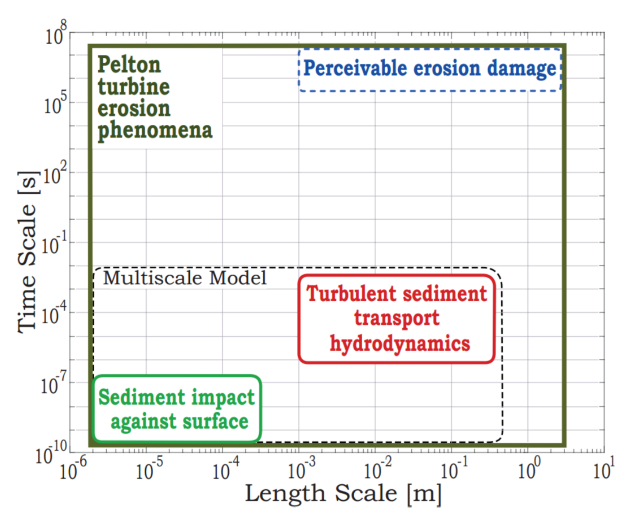
2.1. Multiscale Model of Erosion

Many problems found in science and engineering are typically multiscale in nature, meaning that the macroscopic behavior (accessible to the observer) is a consequence of myriad microscopic processes. Although some problems lend themselves to a simplified macroscopic model, in which the details at the microscale are neglected, others depend fundamentally on a correct description of the microscale. Multiscale approaches have been used to model a variety of problems [18,19,20]; in such models, two or more sub-models were coupled across time and length scales, in order to improve the accuracy of the macroscale description with the detailed input of the microscale description.
The erosion of a hydraulic turbine is an inherently multiscale phenomenon: It is a progressive process affecting broad areas, yet it is the consequence of billions upon billions of microscopic particle impacts. This multiscale character is shown, in Figure 1, for the specific instance of a Pelton runner: Whilst the particles accountable for the erosion are about 100 μ m in diameter [1,17] and their collisions only last for about 0.1 μ s [21,22], the damage entailed slowly accumulates over months of operation and involves significant portions of the bucket surface.
Recently, a multiscale model of erosion has been introduced [17], which was shown to provide improved accuracy, when compared to the state-of-the-art erosion models based on empirical correlations. A full description of the physical models employed is not within the scope of this article, which is focused on an application. For this reason, only an overview of the model follows, given that the details are published in the aforementioned reference, including the governing equations, an analysis of the model convergence, and its validation.

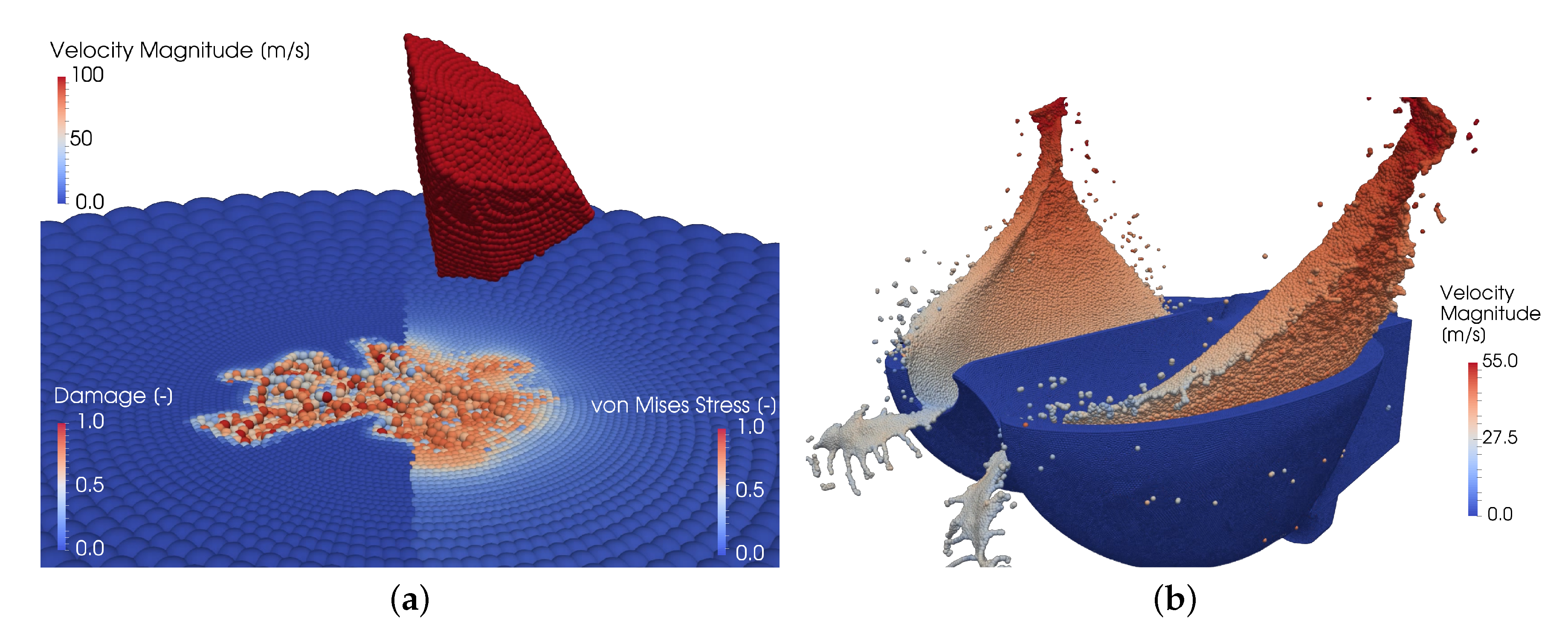
2.2. Microscale Model: Sediment Impacts

In the microscale model, detailed simulations of the sediment impacts and the resulting material damage and removal are performed, instead of relying on empirical erosion correlations to estimate the amount of mass removed by a given impact.
The mass and linear momentum conservation equations are resolved for the sediments and the base material, referred to hereafter as the solid. Both materials are modeled as isotropic and homogeneous, together with the Mie–Grüneisen equation of state to calculate the pressure. Whereas the sediments are modeled as elastic, the solid is considered as elasto-plastic by means of the Johnson–Cook constitutive and damage models [23], which define the flow stress and plastic strain at failure as functions of the strain, strain-rate, temperature, and triaxiality states, as studied in [24]. Material heating caused by the friction force and plastic deformation is also taken into account.

2.3. Macroscale Model: Turbulent Sediment Transport

In the macroscale model, the turbulent sediment transport, the impact detection between wall and sediments, and the accumulation of eroded mass are calculated on the domain.
The mass and linear momentum conservation equations are resolved for the fluid, assumed to be Newtonian and weakly compressible; the Tait equation of state is used to calculate the pressure, whereas the standard k-ϵ model and wall function are used to describe the turbulence. The particles, modeled as discrete masses, are transported by the fluid by means of a one-way coupled scheme. Apart from inter-particle contact, the sediments are subject to the hydrodynamic forces due to drag, pressure gradient, and added mass. The dispersion caused by turbulence is implemented by solving the stochastic Langevin equation [25].

2.4. Sequential Multiscale Coupling Strategy

The models are coupled in a sequential manner. Firstly, a number of independent simulations of the microscale model are run to characterize the space of impact conditions; each one of these involves about 80 impacts, with constant velocity, angle, sediment sphericity, and size, on a hemispherical specimen of the material. The results of these simulations are the average coefficients of restitution and the steady-state erosion ratio, defined as the average amount of mass eroded per unit mass of sediment that impacts, as functions of the impact condition. Secondly, a simulation of the macroscale model is run, in which the turbulent particle transport around the geometry under study is calculated; whenever a sediment contacts the wall, the microscale simulation results for the restitution coefficients are used to compute the particle rebound velocity, whereas the steady-state erosion ratio and the sediment mass are used to calculate the eroded mass. After enough impacts, converged distributions of eroded mass and average impact conditions on the geometry under study are obtained.

2.5. The Finite Volume Particle Method

The governing equations are solved by time integration, after being discretized in the framework of the finite volume particle method (FVPM), which is a certain generalization of the traditional finite volume method, in the sense that the computational volumes are spherical (therefore referred to as particles) and are allowed to overlap. FVPM is based on the Arbitrary Lagrangian–Eulerian (ALE) formalism, such that the particles are allowed to move with an arbitrary velocity. This flexibility is advantageous for describing dynamic interfaces; for example, a fluid-free surface or a wall subject to erosion. A complete derivation of the 3D FVPM formulation, the GPU implementation, a variety of validation case studies, and applications are accessible in the literature [24,26,27,28,29,30].

3. Test Case Description

With the objective of testing its applicability to realistic problems of interest to the industry, the multiscale model was used to simulate the erosion of a prototype-scale Pelton bucket impinged by a water jet with sediments. A non-rotating bucket setup was chosen for this simulation.
The test case closely followed the experimental case reported in [7], which involved the Toss hydro power plant in the Himalayan region of India. Given that it was not possible to obtain the bucket geometry, the design reported by Perrig [31] was used, scaled to exactly match the dimensions of its experimental counterpart. As the simulated bucket was not rotating, the experimental relative velocity between the jet and the bucket was used for the simulated jet velocity. All the test case parameters are reported in Table 1; the corresponding nomenclature is explained in the Abbreviations section at the end of the article.
In the macroscale simulation, the jet length was calculated such that the amount of water injected was equivalent to the amount received by a bucket in the experiment during half a jet pass, by considering the pitch diameter and the angular separation between buckets. Sediment diameters were randomly drawn from the average size distribution reported in the experiment, and were distributed uniformly in the water volume following a concentration representative of the experimental conditions, resulting in a total of about 980,000 sediment particles.
The FVPM discretizations used are presented in Figure 2. Microscale simulations, encompassing 50–100 impacts each, were performed for five impact angles and four impact velocities, prior to the macroscale simulation; the sediment discretizations were generated according to the algorithm reported in [22]. The computations were performed on the Piz Daint supercomputer at the Swiss National Supercomputing Centre (CSCS) in Lugano, Switzerland. Each microscale simulation, which contained 85,000 FVPM particles, took, on average, 250 h using 4 NVIDIA Tesla P100 GPUs. The macroscale simulation, which contained 1,465,000 FVPM particles, took 650 h using 24 GPUs. Thus, the total computational cost of the simulations was equal to about 24,000 GPU-hours.

4. Results

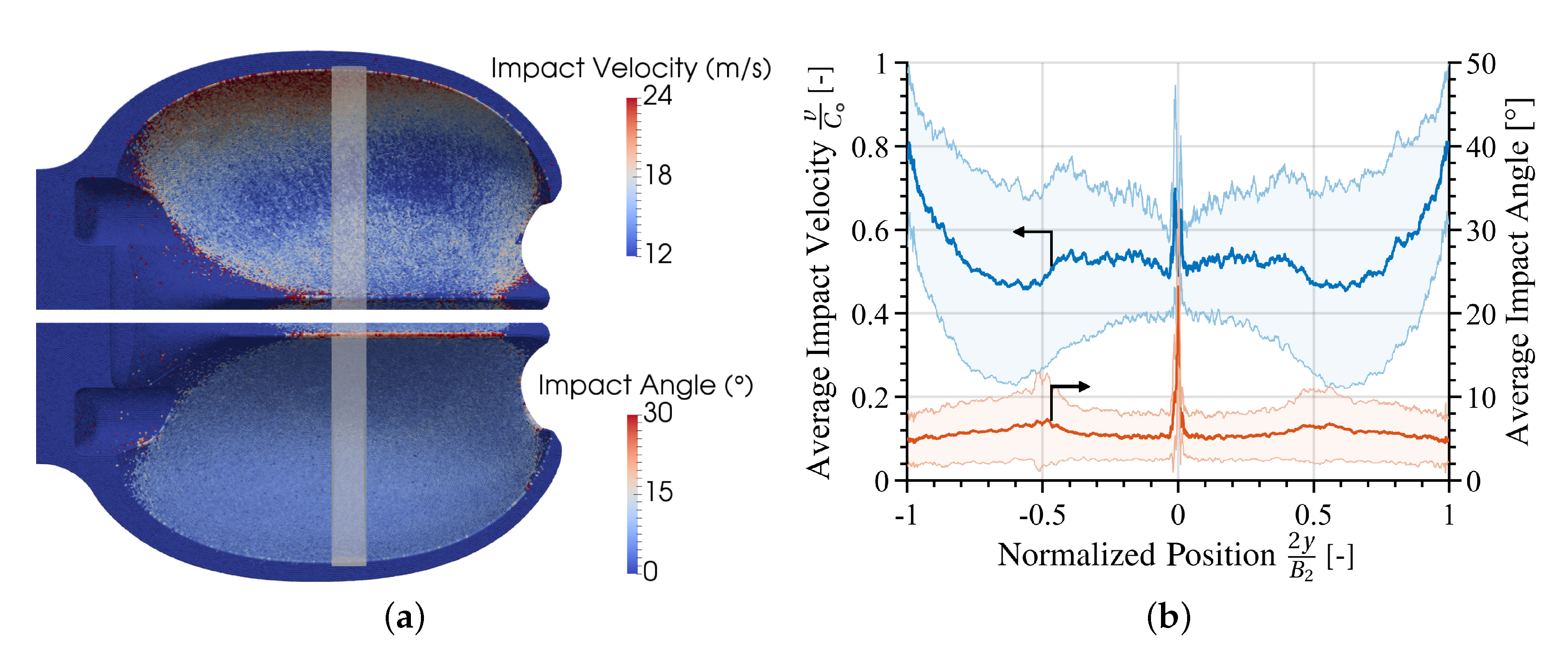
4.1. Distributions of Impact Conditions on the Bucket Surface

Figure 3 presents the results of the average sediment impact velocity and angle, where 90 corresponds to a perpendicular impact, on the bucket surface and on a slice corresponding to the pitch diameter position. The impact velocity was about 0.5 C exactly at the splitter center, due to the acceleration felt by the sediments as a consequence of the low-velocity stagnation zone, although on the splitter edges it was as high as 0.7 C . Throughout most of the bucket, the impact velocity was about 0.5 C , with increasing values towards the bucket outlet, reaching a maximum average impact velocity of 0.8 C . On the other hand, the average impact angle was fairly uniform throughout the bucket, with a value of about 5 ; except for the splitter, where the impacts occurred at about 25 . The fact that the sediments did not impact at higher angles on the splitter indicates that they were fairly responsive to the fluid acceleration. These impact condition results are very similar to the 2D results [32] of the same test case.

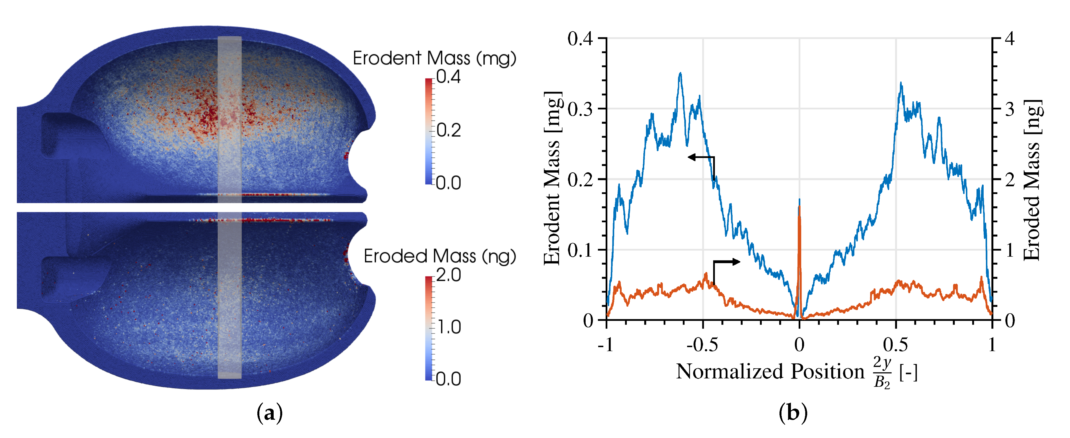
4.2. Erosion Distribution of the Bucket Surface

Figure 4 presents the distribution of erodent mass that has impacted and eroded mass on the bucket surface, and on a slice corresponding to the pitch diameter position. The distribution of erodent mass reveals that most of the sediment impacts occurred on the bucket depth, which corresponds to the zone of maximum bucket curvature. These results highlight the fact that one of the driving mechanisms for sediment flux against the wall, the sediment inertia, is directly linked to the surface curvature. The second hot-spot for sediment impacts was the splitter. The sum of erodent mass impacted on the surface was equal to 2.66 times the sum of sediment mass injected, highlighting the fact that sediments tended to impact several times along their path through the bucket.
The superposition of the aforementioned distributions (i.e., where the sediments tended to impact and at what angle and velocity) determines the distribution of eroded mass presented in Figure 4. The amount of eroded mass per unit area had a peak at the splitter and almost vanished immediately downstream; it gradually increased again, towards the bucket outlet. It is noteworthy that the distribution of erosion did not only depend on the flux of the erodent towards the wall: Even though the sediment mass impacted was greatest at the bucket depth, the eroded mass was greatest at the splitter because of the higher average impact angle at that location. Similarly, in spite of the relatively low erodent mass impacted towards the bucket outlet, the eroded mass was maintained due to the higher impact velocity at that location. Yet again, these erosion distribution results are similar to the 2D results [32] of the same test case.
The global erosion ratio computed was equal to 4.04 mg kg 1 . In other words, at these sediment and hydrodynamic conditions, the bucket lost about 4.0 kg of material for every 1000 tons of sediment injected. According to the following validation, this value predicted by the multiscale simulation was quite close to its experimental counterpart.

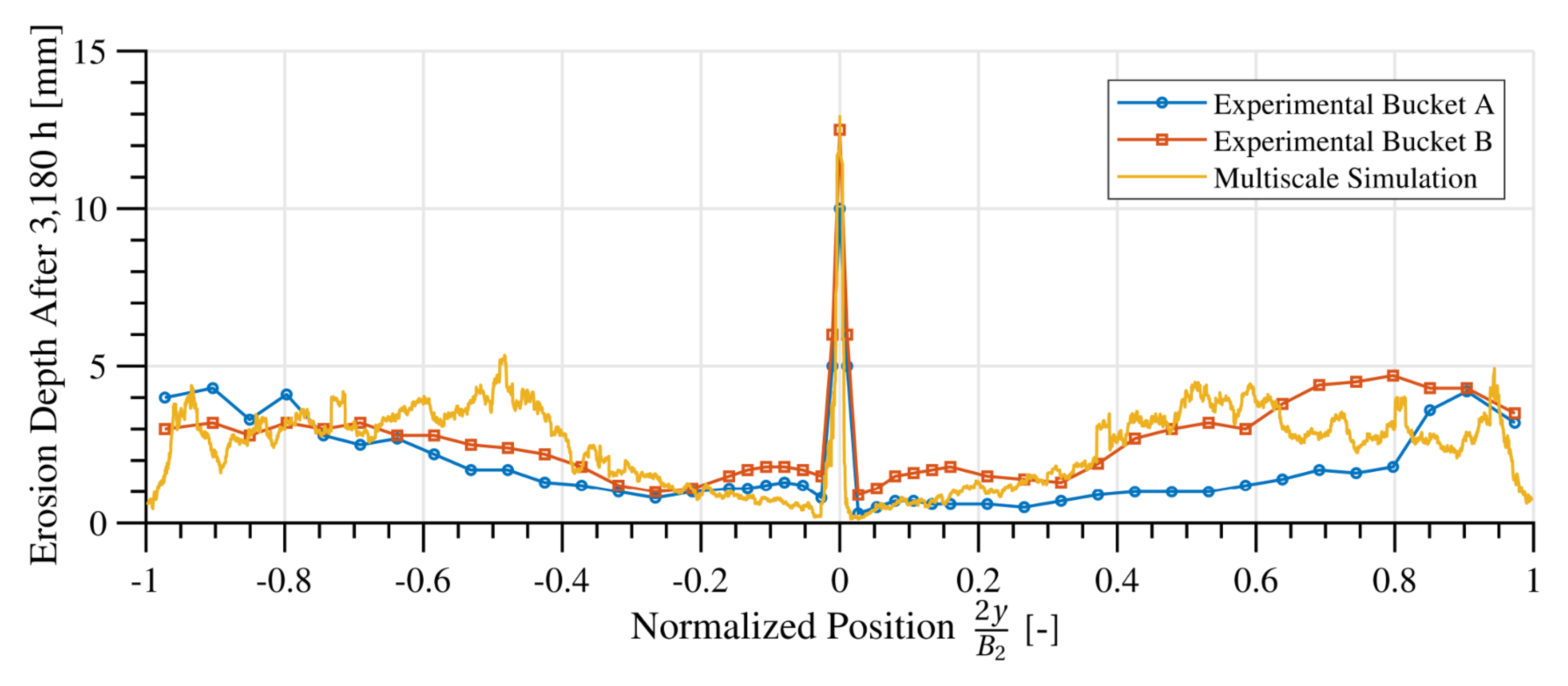
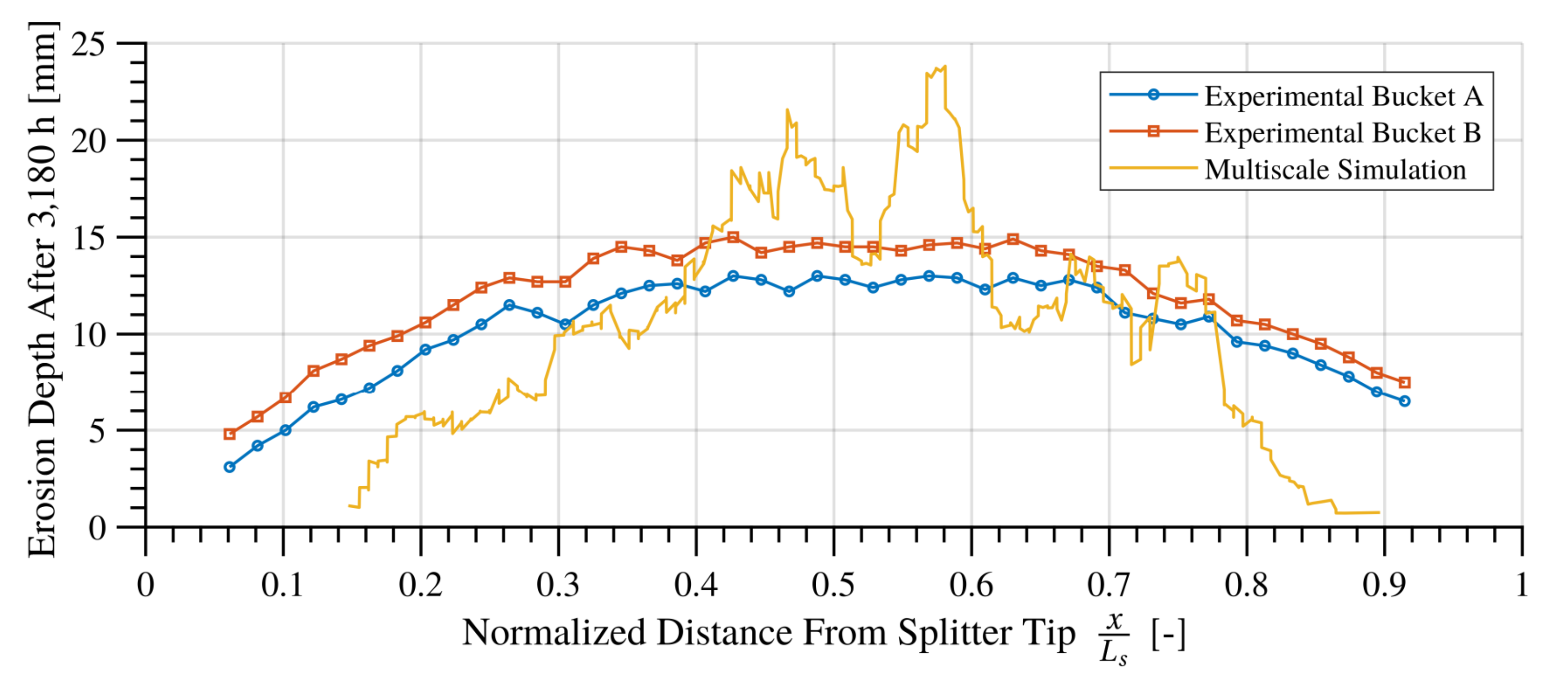
4.3. Erosion Depth Validation

The multiscale model described bridges the scale separation between the sediment impact dynamics and the sediment transport hydrodynamics. A projective integration extension has been presented [32] that allows simulation of the long-term erosion process by including the surface evolution in time, thus bridging the gap between the hydrodynamics and the surface erosion accumulation. The projective integration approach involves running the multiscale model for successive states of the eroded surface, whose evolution is determined by the erosion rate distribution calculated on each of the multiscale model instances. This approach is able to capture the effect the surface erosion has on subsequent erosion rates.
However, the projective integration approach is too computationally expensive to apply to this 3D test case, as it involves several successive macroscale simulations. In consequence, the long-term erosion distribution is estimated by extrapolating the erosion rate distribution obtained on the original bucket, not including the surface alteration induced by the process. Note that the incubation period (the initial delay in erosion due to the preliminary accumulation of damage in the surface) is considered in the microscale model by performing enough sediment impacts to reach the steady-state erosion ratio; what is neglected in the aforementioned extrapolation is the effect of the macroscopic surface alteration, such as wavy patterns and increased roughness, and the resulting modification of the hydrodynamics and, therefore, of the erosion rate.
The total amount of sediments injected in the simulation was equal to 3.43 g along a physical time of about 0.03 s. Rai et al. [7] reported on the erosion depth distribution after 3180 h of operation, after which 12,540 tons of sediment had traversed the turbine (i.e., 737.65 tons through each one of the 17 buckets). Therefore, the factor used to linearly extrapolate the simulation results to the time frame reported in the experiments was f extrap . = 737,650 kg 0.00343 kg = 2.15 × 10 8 .
The eroded depth, after 3180 h, is calculated as
e d = f extrap . m e ρ A i ,
where ρ is the base material density, m e is the total eroded mass accumulated on each FVPM particle on the bucket surface, and A i is the surface area of each one of the particles. That is, the eroded mass distribution presented in Figure 4 can be directly linked to a distribution of eroded depth, that is then extrapolated to the time frame of the experiment by means of f extrap . .
Figure 5 presents the multiscale simulation prediction of the erosion depth distribution on the pitch diameter position after 3180 h of operation, as well as the corresponding measurements reported by Rai et al. [7] on two different buckets. The remarkable agreement between the simulation and the experiment is highlighted, considering the complexity and astounding range of time and length scales involved. Notice that the differences between the two experimental buckets, and even between the two sides of each bucket, is of comparable magnitude to the difference between the experimental data and the simulation results. There is a considerable amount of noise in the numerical results because of the short simulation duration and the corresponding low number of sediments tracked. The smoothness of the simulated erosion profiles is bound to increase if a higher number of sediment particless are injected, as with any process influenced by randomness; in this case, the sediment trajectories were affected by the turbulent fluctuations, and the signal-to-noise ratio would increase by having more samples.
The multiscale simulation prediction of the erosion depth distribution on the bucket splitter is presented in Figure 6, together with the corresponding measurements reported by Rai et al. [7] on two different buckets. Whereas the experimental erosion was widely distributed along the splitter, the simulated erosion was concentrated towards its center. Indeed, as the experimental bucket rotates, the jet is allowed to impinge at different locations along the splitter, whereas, in the simulated static bucket, it only impinged at its center. Apart from this discrepancy and the overall lack of smoothness evidenced in the simulated erosion depth, the results agree to a significant extent.

5. Discussion and Conclusions

For the first time, it has become possible to quantitatively predict the erosion process of an industrial-scale hydraulic turbine. This achievement is possible thanks to the use of a multiscale model that bridges the scale separation between the sediment impact dynamics and the turbulent sediment transport hydrodynamics. This approach bypasses the need for uncertain erosion correlations by relying on accurate simulations of the sediment impacts, taking into consideration the sediment shape and elasticity and the high strain rate response of the base material, by means of comprehensive physical models. Not only does the model accurately predict the erosion distribution on the bucket surface; it also brings information concerning the impact conditions and sediment flux against the wall, which allows for a better understanding of the erosion distribution results.
In the 2D version of the test case, that included long-term evolution of the bucket surface [32], a significant feedback effect was evidenced in which the bucket surface state, altered by the erosion, implied an increase of the erosion rate of up to 45% (compared to the one calculated on the un-eroded surface). Consequently, erosion prediction based on the original bucket geometry, as done in the present test case, might lead to an under-prediction of the long-term bucket erosion by perhaps around 30%, provided that the aforementioned feedback effect is indeed accurate. This would imply that the erosion depth results presented in Figure 5 and Figure 6 might not be as good as they appear. However, even an error on the order of 30% would not be unexpected, considering the differences between the simulation and the experiment: The fact that the jet impinges at a constant angle on the simulated static bucket, the geometric discrepancy between the experimental runner and the available bucket geometry used for the simulation, and the linear extrapolation that bridges eight orders of magnitude in time. Still, the presented results are by far the most accurate prediction of the erosion of an industrial-scale component found in the literature, where, at best, a qualitative agreement with experiments is reported.
Current work is underway to simulate the erosion of a rotating Pelton runner [33], for which both the geometry and the erosion measurements have recently been made available. Once the model is thoroughly validated, it might be used as a predictive tool in the design and optimization of hydraulic turbines and in the operation of run-of-the-river hydroelectric installations, by estimating the sediment concentration threshold for preventive shutdown based on an economic analysis.

Author Contributions

S.L. developed the multiscale methodology, ran and evaluated the simulations, and wrote the article. E.J., S.A., and S.L. developed and validated the in-house software used. E.J., A.M., and F.A. advised in the computational and simulation aspects of the investigation, and provided detailed reviews of the manuscript. F.A. acquired the financial support and managed the project.

Funding

This research was funded by the Swiss Commission for Technology and Innovation (CTI) with grant No. 17568.1 PFEN-IW; by the Swiss Federal Office of Energy (SFOE) under contract SI/501786-01; and by the Swiss Competence Center for Energy Research—Supply of Electricity (SCCER-SoE). This work was supported by a grant from the Swiss National Supercomputing Centre (CSCS) under project ID s777.

Acknowledgments

The authors would like to thank General Electric Renewable Energy for their financial support and technical assistance.

Conflicts of Interest

The authors declare no conflict of interest.

Abbreviations

The following abbreviations are used in this manuscript:
Variables
A i Surface area
B 2 Maximum internal bucket width
C Jet velocity
D 1 Runner pitch diameter
D 2 Jet diameter
L j Jet length
L s Splitter length
cSediment concentration by mass
d x Sediment diameter below which x% of the cumulative mass distribution lies
e d Eroded depth
f extrap . Extrapolation factor
m e Eroded mass
vSediment impact velocity
z r Number of buckets
α Jet impinging angle relative to the bucket plane
ρ Base material density
Abbreviations
ALEArbitrary Lagrangian-Eulerian
FVPMFinite Volume Particle Method
GPUGraphics Processing Unit

References

  1. Grein, H.; Schachenmann, A. Solving problems of abrasion in hydroelectric machinery. Water Power Dam Construct. 1992, 44, 19–24. [Google Scholar]
  2. Chitrakar, S.; Neopane, H.; Gunnar, O. Study of the simultaneous effects of secondary flow and sediment erosion in Francis turbines. Renew. Energy 2016, 97, 881–889. [Google Scholar] [CrossRef]
  3. Felix, D.; Abgottspon, A.; Albayrak, I.; Boes, R. Hydro-abrasive erosion on coated Pelton runners: Partial calibration of the IEC model based on measurements in HPP Fieschertal. In Proceedings of the 28th IAHR Symposium on Hydraulic Machinery and Systems, Grenoble, France, 4–8 July 2016; Volume 49, p. 122009. [Google Scholar] [CrossRef]
  4. Finnie, I. Erosion of surfaces by solid particles. Wear 1960, 3, 87–103. [Google Scholar] [CrossRef]
  5. Finnie, I. Some observations on the erosion of ductile materials. Wear 1972, 19, 81–90. [Google Scholar] [CrossRef]
  6. Shewmon, P.; Sundararajan, G. The erosion of metals. Annu. Rev. Mater. Sci. 1983, 13, 301–318. [Google Scholar] [CrossRef]
  7. Rai, A.; Kumar, A.; Staubli, T. Hydro-abrasive erosion in Pelton buckets: Classification and field study. Wear 2017, 392–393, 8–20. [Google Scholar] [CrossRef]
  8. Mann, B.; Arya, V. Abrasive and erosive wear characteristics of plasma nitriding and HVOF coatings: Their application in hydro turbines. Wear 2001, 249, 354–360. [Google Scholar] [CrossRef]
  9. Thapa, B.S.; Thapa, B.; Dahlhaug, O.G. Empirical modelling of sediment erosion in Francis turbines. Energy 2012, 41, 386–391. [Google Scholar] [CrossRef]
  10. Wang, Y.F.; Yang, Z.G. Finite element model of erosive wear on ductile and brittle materials. Wear 2008, 265, 871–878. [Google Scholar] [CrossRef]
  11. Balu, P.; Kong, F.; Hamid, S.; Kovacevic, R. Finite element modeling of solid particle erosion in AISI 4140 steel and nickel-tungsten carbide composite material produced by the laser-based power deposition process. Tribol. Int. 2013, 62, 18–28. [Google Scholar] [CrossRef]
  12. Wang, Y.F.; Yang, Z.G. A coupled finite element and meshfree analysis of erosive wear. Tribol. Int. 2009, 42, 373–377. [Google Scholar] [CrossRef]
  13. Takaffoli, M.; Papini, M. Material deformation and removal due to single particle impacts on ductile materials using smoothed particle hydrodynamics. Wear 2012, 274, 50–59. [Google Scholar] [CrossRef]
  14. Wang, M.H.; Huang, C.; Nandakumar, K.; Minev, P.; Luo, J.; Chiovelli, S. Computational fluid dynamics modelling and experimental study of erosion in slurry jet flows. Int. J. Comput. Fluid Dyn. 2009, 23, 155–172. [Google Scholar] [CrossRef]
  15. Grewal, H.S.; Singh, H.; Yoon, E.S. Interplay between erodent concentration and impingement angle for erosion in dilute water-sand flows. Wear 2015, 332, 1111–1119. [Google Scholar] [CrossRef]
  16. Messa, G.V.; Malavasi, S. The effect of sub-models and parametrizations in the simulation of abrasive jet impingement tests. Wear 2017, 370–371, 59–72. [Google Scholar] [CrossRef]
  17. Leguizamón, S.; Jahanbakhsh, E.; Maertens, A.; Alimirzazadeh, S.; Avellan, F. A multiscale model for sediment impact erosion simulation using the finite volume particle method. Wear 2017, 392–393, 202–212. [Google Scholar] [CrossRef]
  18. Abdulle, A.; Weinan, E.; Engquist, B.; Vanden-Eijnden, E. The heterogeoeous multiscale method. Acta Numer. 2012, 21, 1–87. [Google Scholar] [CrossRef]
  19. Walther, J.H.; Praprotnik, M.; Kotsalis, E.M.; Koumoutsakos, P. Multiscale simulation of water flow past a C-540 fullerene. J. Comput. Phys. 2012, 231, 2677–2681. [Google Scholar] [CrossRef]
  20. Saye, R.I.; Sethian, J.A. Multiscale modeling of membrane rearrangement, drainage, and rupture in evolving foams. Science 2013, 340, 720–724. [Google Scholar] [CrossRef] [PubMed]
  21. Yildirim, B.; Muftu, S.; Gouldstone, A. Modeling of high velocity impact of spherical particles. Wear 2011, 270, 703–713. [Google Scholar] [CrossRef]
  22. Leguizamón, S.; Jahanbakhsh, E.; Alimirzazadeh, S.; Maertens, A.; Avellan, F. FVPM numerical simulation of the effect of particle shape and elasticity on impact erosion. Wear 2019, 430–431, 108–119. [Google Scholar] [CrossRef]
  23. Johnson, G.R.; Cook, W.H. Fracture characteristics of three metals subjected to various strains, strain rates, temperatures and pressures. Eng. Fract. Mech. 1985, 21, 31–48. [Google Scholar] [CrossRef]
  24. Leguizamón, S.; Jahanbakhsh, E.; Maertens, A.; Vessaz, C.; Alimirzazadeh, S.; Avellan, F. Impact erosion prediction using the finite volume particle method with improved constitutive models. In Proceedings of the 28th IAHR Symposium on Hydraulic Machinery and Systems, Grenoble, France, 4–8 July 2016; Volume 49, p. 122010. [Google Scholar] [CrossRef]
  25. Dehbi, A. Turbulent particle dispersion in arbitrary wall-bounded geometries: A coupled CFD-Langevin-equation based approach. Int. J. Multiphase Flow 2008, 34, 819–828. [Google Scholar] [CrossRef]
  26. Jahanbakhsh, E.; Vessaz, C.; Maertens, A.; Avellan, F. Development of a finite volume particle method for 3-D fluid flow simulations. Comput. Methods Appl. Mech. Eng. 2016, 298, 80–107. [Google Scholar] [CrossRef]
  27. Vessaz, C.; Jahanbakhsh, E.; Avellan, F. Flow simulation of jet deviation by rotating Pelton buckets using finite volume particle method. ASME J. Fluids Eng. 2015, 137, 074501. [Google Scholar] [CrossRef]
  28. Jahanbakhsh, E.; Maertens, A.; Quinlan, N.; Vessaz, C.; Avellan, F. Exact finite volume particle method with spherical-support kernels. Comput. Methods Appl. Mech. Eng. 2017, 317, 101–127. [Google Scholar] [CrossRef]
  29. Alimirzazadeh, S.; Jahanbakhsh, E.; Maertens, A.; Leguizamón, S.; Avellan, F. GPU-accelerated 3-D finite volume particle method. Comput. Fluids 2018, 171, 79–93. [Google Scholar] [CrossRef]
  30. Alimirzazadeh, S.; Kumashiro, T.; Leguizamón, S.; Maertens, A.; Jahanbakhsh, E.; Tani, K.; Avellan, F. GPU-accelerated Pelton turbine simulation using finite volume particle method coupled with linear eddy viscosity models. In Proceedings of the 29th IAHR Symposium on Hydraulic Machinery and Systems, Kyoto, Japan, 17–21 September 2018; Volume 240, p. 072018. [Google Scholar] [CrossRef]
  31. Perrig, A. Hydrodynamics of the Free Surface Flow in Pelton Turbine Buckets. Ph.D. thesis, École Polytechnique Fédérale de Lausanne (EPFL), Lausanne, Switzerland, 2007. [Google Scholar] [CrossRef]
  32. Leguizamón, S.; Jahanbakhsh, E.; Maertens, A.; Alimirzazadeh, S.; Avellan, F. Simulation of the hydroabrasive erosion of a bucket: A multiscale model with projective integration to circumvent the spatio-temporal scale separation. In Proceedings of the 29th IAHR Symposium on Hydraulic Machinery and Systems, Kyoto, Japan, 17–21 September 2018; Volume 240, p. 072014. [Google Scholar] [CrossRef]
  33. Leguizamón, S.; Alimirzazadeh, S.; Jahanbakhsh, E.; Avellan, F. Multiscale simulation of erosive wear in a prototype-scale Pelton runner. Renew. Energy 2019, submit. [Google Scholar]
Figure 1. Time and length scales involved in the erosion process of a Pelton turbine [17]. The time bounds represent the simulation time step required and its overall duration, whereas the length bounds represent the discretization size necessary for convergence and the overall domain size.
Ijtpp 04 00009 g001
Figure 2. Finite volume particle method (FVPM) discretizations used in the multiscale model. (a) Microscale domain, where a sharp sediment is about to impact the solid. (b) Macroscale domain, where the water (with sediments too small to be seen) is being evacuated from the Pelton bucket.
Ijtpp 04 00009 g002
Figure 3. Average sediment impact velocity and angle distributions on the bucket surface (a) and on the pitch diameter position (b). The values presented in (b) are taken from the rectangular stripe illustrated in (a); the shaded region represents ± one standard deviation.
Ijtpp 04 00009 g003
Figure 4. Erodent mass (i.e., the amount of sediment that impacted) and eroded mass (i.e., the amount of base material removed), on the bucket surface (a) and on the pitch diameter position (b). The values presented in (b) are taken from the rectangular stripe illustrated in (a).
Ijtpp 04 00009 g004
Figure 5. Eroded depth distribution on the pitch diameter position after 3180 h of operation; the multiscale simulation results compare well with the corresponding experimental data of Rai et al. [7].
Ijtpp 04 00009 g005
Figure 6. Eroded depth distribution on the bucket splitter after 3180 h of operation, including the experimental data of Rai et al. [7].
Ijtpp 04 00009 g006
Table 1. Test Case Geometric Parameters.
B 2 D 1 D 2 z r C α L j c d 10 d 50 d 90
37510891401728.5802011174627134
[ mm ] [ mm ] [ mm ] [ ] [ m s 1 ] [ ] [ mm ] [ mg L 1 ] [ μ m ] [ μ m ] [ μ m ]

