Article

A Human-Computer Control System Based on Intelligent Recognition of Eye Movements and Its Application in Wheelchair Driving

1
Graduate School of Engineering, Saitama Institute of Technology, Fukaya 369-0217, Japan
2
Ningbo Haizhi Institute of Materials Industry Innovation, Ningbo 315033, China
3
Tokyo Green Power Electric Research Institute Co., Ltd., Tokyo 111-0022, Japan
*
Author to whom correspondence should be addressed.
Multimodal Technol. Interact. 2021, 5(9), 50; https://doi.org/10.3390/mti5090050
Submission received: 3 May 2021 / Revised: 21 August 2021 / Accepted: 24 August 2021 / Published: 28 August 2021

Abstract

:
This paper presents a practical human-computer interaction system for wheelchair motion through eye tracking and eye blink detection. In this system, the pupil in the eye image has been extracted after binarization, and the center of the pupil was localized to capture the trajectory of eye movement and determine the direction of eye gaze. Meanwhile, convolutional neural networks for feature extraction and classification of open-eye and closed-eye images have been built, and machine learning was performed by extracting features from multiple individual images of open-eye and closed-eye states for input to the system. As an application of this human-computer interaction control system, experimental validation was carried out on a modified wheelchair and the proposed method proved to be effective and reliable based on the experimental results.

1. Introduction

Human-computer interaction (HCI) has been widely studied since the 1960s with the rapid development of information systems, which aims to design a human-computer interface with ergonomic characteristics [1]. HCI systems in automated devices have been based on the traditional interface with the monitor, keyboard, and mouse for a long time. However, this manual input HCI was cumbersome to use, and to change this situation, HCI with gesture-controlled interfaces has been widely studied [2,3,4]. Nevertheless, there are many physically disabled people in real life who still are unable to use these devices or even to travel independently. These physically disabled people are completely dependent on others for their daily needs [5]. In order to improve the quality of life for people with disabilities, HCI systems without relying on hands and feet is particularly important.
In recent years, there has been much research on control systems for people with ALS (amyotrophic lateral sclerosis) and other severe physical disabilities that use biological information such as eye movements, EEG, and EMG directly for HCI, without the use of hands and feet [6,7,8,9,10,11,12]. As some particular interest research works are studies on eye gaze input and eye blink, etc., which transmit information through the human eye. Because the signal conveyed by the eye has greater stability and real-time compared to EEG and EMG, humans can communicate a great deal of information more quickly and directly through the eye [13,14,15,16,17,18,19,20,21,22,23,24,25]. Additionally, the problem of calibration in eye gaze regarding the difficulty recognition was obtained due to the method using smooth pursuit motion does not require calibration, which is of interest for eye gaze input studies because it makes the calibration of gaze input easy [21].
This paper presents a practical HCI system for wheelchair control. Eye tracking and eye blink detection based on image processing techniques have been integrated into the proposed system. Since subjects can convey incorrect information when they are slightly inattentive during eye gaze interactions, eye blink detection was introduced to assist in completing this study. In contrast to some commonly used methods [22,23,24,25], image processing techniques were applied as a new approach, which improved the reliability and convenience of the system. After the captured image was processed by image processing, its features were extracted, which made it easier to be recognized and the accuracy of recognition becomes higher. Similarly, the eye object detection module in the Haar Cascade (a Face Recognition Module) was used in the program, and as soon as the system turned on, it was able to quickly capture and locate the eye region from the images captured by the camera.
In this study, for eye gaze detection, pupil features were extracted from the eye images using image binarization. The eyeball movement trajectory was tracked by locating the pupil, based on the eyeball movement trajectory, the subject’s eye gaze area was determined so that the information that the subject wants to express through eye gaze can be obtained. For eye blink detection, some machine learning methods have been used to accomplish eye blink detection in order to solve the problems of low accuracy, lack of stability, and inconvenience of use of other methods. Machine learning techniques were used very successfully in the field of computer vision, where it was used to simulate human intelligence by learning the surrounding environment [26]. Machine learning was used in this study to extract image features of the open and closed states of multiple individual eyes to obtain a learning model so that the system could discriminate whether a subject the eye blink or not by take real-time eye images of the subject. Three methods have been used to determine the eye blink: pixel ratio [27], support vector machine (SVM) [28], and convolutional neural network (CNN) [29] to determine eye blink. In comparison, using CNN had the highest accuracy in detecting eye blink.
The HCI system of this study was mounted on a modified electric wheelchair for experimental validation. Experiments with many methods to drive wheelchairs for disabled people have been used in many HCI systematic studies, which gives us some references [30,31,32,33,34,35,36]. Based on the data obtained in the experiments, it can be demonstrated that this integrated multi-domain interaction system is effective. This also provides some basis for further research on gaze interaction and HCI.

2. HCI Control System of Wheelchairs

2.1. System Overview

The HCI system of this study was applied to control the movement of an electric wheelchair (see Figure 1). The testing system included a blink detection device, head-mounted eye gaze tracking device (see Figure 1). Wireless communication was used between the interactive system and the wheelchair, and the subject used eye gaze direction and eye blink to control the wheelchair movement. Throughout the process of controlling the movement of the wheelchair, the subject interacts with the computer, communicating information to the computer through the eyes, and the computer communicates commands to the wheelchair drive unit to control the wheelchair movement.

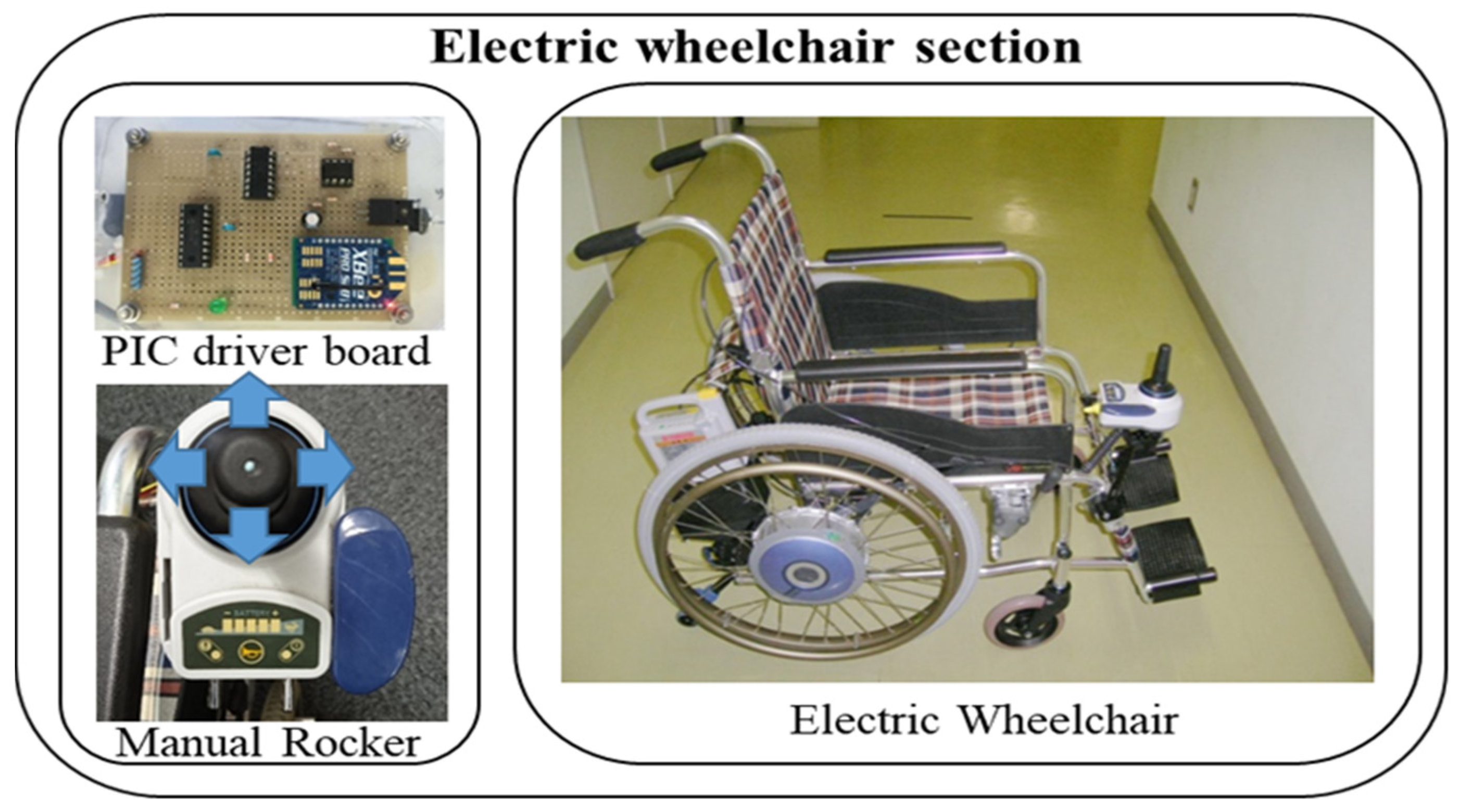
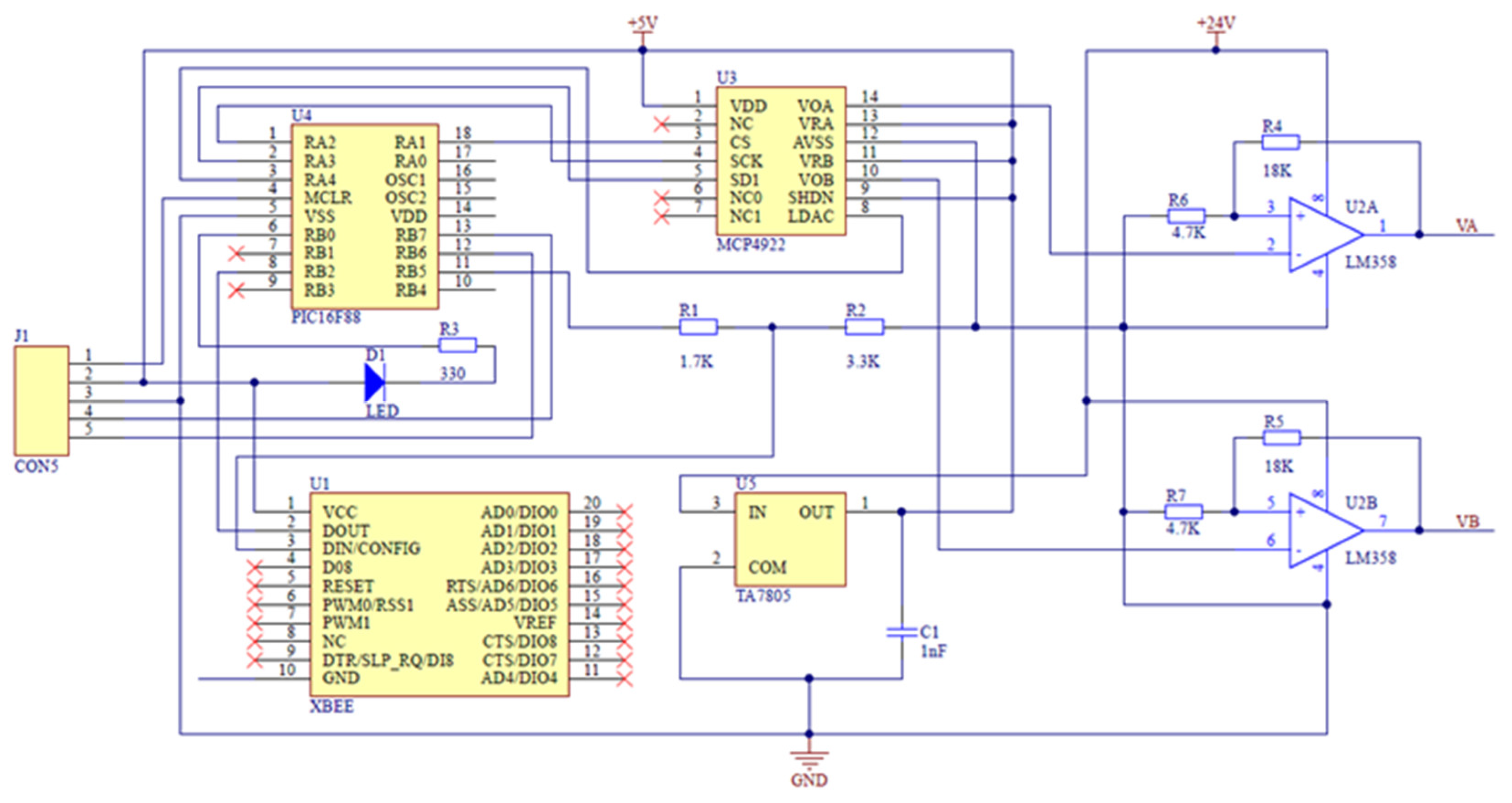
2.2. Hardware Systems for Wheelchairs

In this study, an aluminum AR-200 wheelchair manufactured by Matsunaga Seisakusho Ltd. was used. The hardware part of the wheelchair was improved and we designed a drive unit for the wheelchair. This allows us to control the travel of the electric wheelchair by eye gaze in the direction or by eye blink. In the modification, the rocker control unit of the wheelchair was still retained so that the wheelchair could still be controlled by the rocker when switching to manual operation. Figure 2 shows the hardware of the improved power wheelchair.
In order to be able to drive the wheelchair through the interactive system, a driver board was designed and developed for the wheelchair. Figure 3 shows the circuit schematic of the drive circuit board. This is very important as it makes our interactive system highly portable without having to consider the complex communication protocols of the controlled devices. A wireless communication serial port has been used in the driver board so that wireless communication could be made between the computer and the wheelchair.

3. Eye Movement Recognition Methods

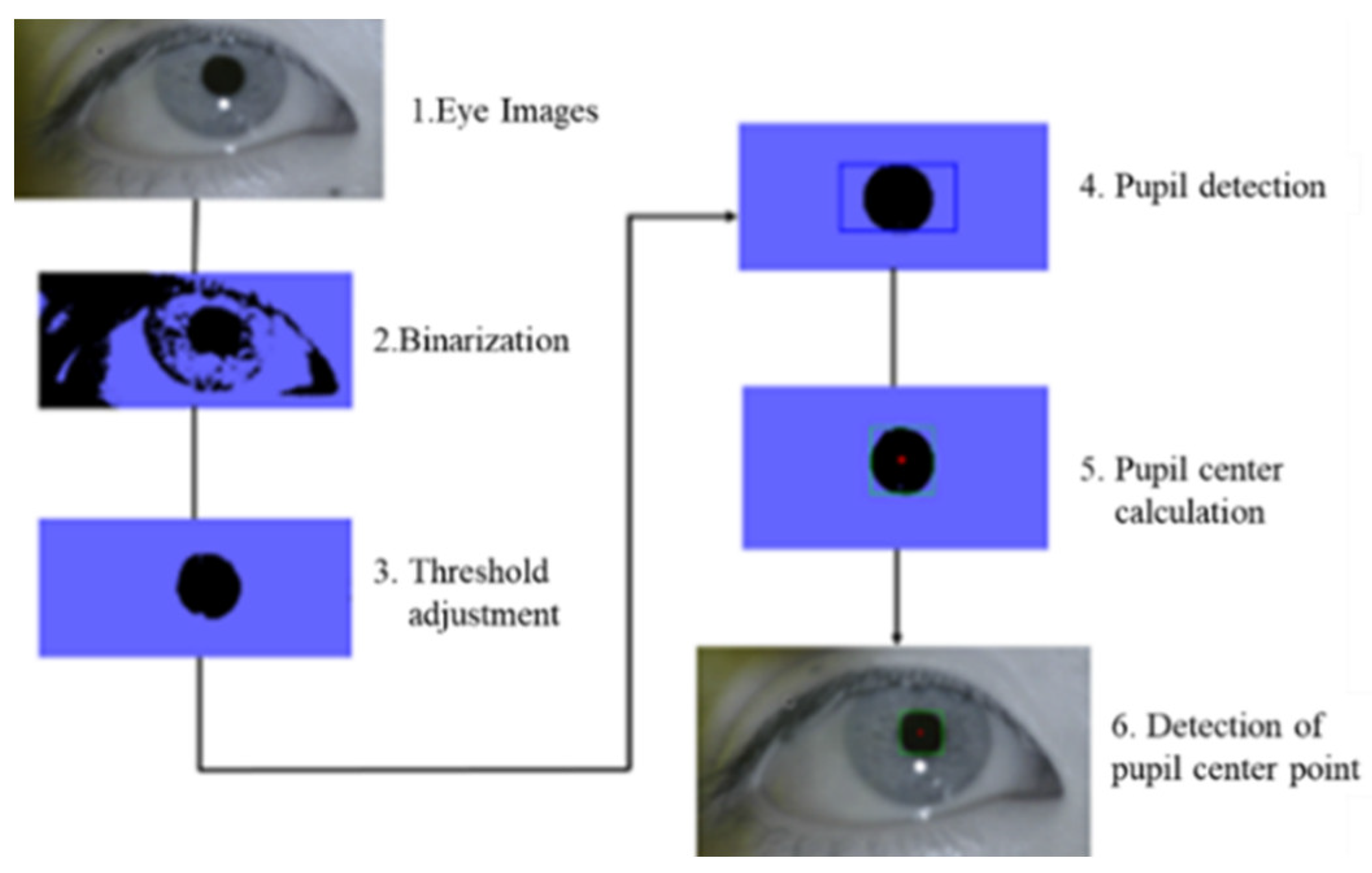
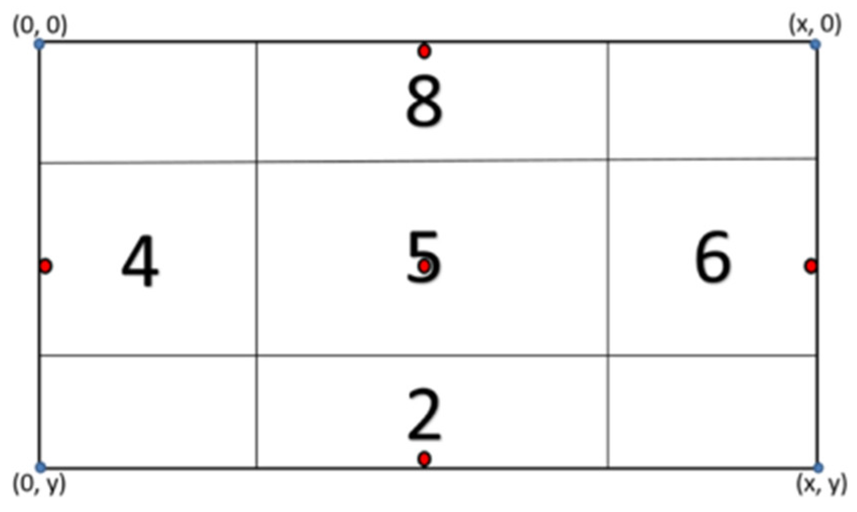
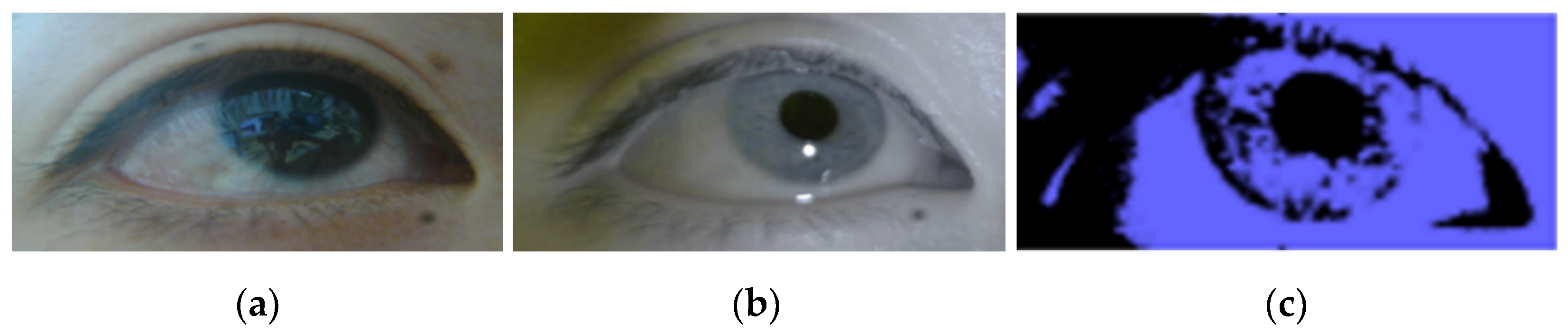
3.1. Eye Gazes Detection Method

The eye gaze tracking device (see Figure 4) used contrast to locate the center of the pupil and used infrared non-columnar light to generate corneal reflections, capturing the black area of the pupil by illuminating the eye with infrared light [17]. In order to be able to use in a variety of light environments like sunlight, a filter was added to the lens, which is to be able to filter out light other than infrared light.
The image binarization method was used to process the captured eye images. Image binarization was the process of converting an image with shadows into two shades of black and white. A threshold was preset, and if the value of each pixel was above the threshold, it was replaced with white, and if it was below the threshold, it was replaced with black.
f ( x ,   y ) = { 255     f ( x , y ) θ     0           f ( x , y ) < θ  
Here, the threshold is θ, the coordinate system is (x, y), the concentration value is f(x, y), and the transformed concentration value is f′(x, y). The flow of the eye tracking technique is shown in Figure 5. The pupil in the eye image was extracted by binarization, and the pupil center coordinates were calculated. The gaze direction can be computed based on the motion trajectory of the pupil center coordinates.
The image of the eye’s moveable range was divided into five regions, and the five regions were labeled 2, 4, 5, 6, and 8 according to the numeric keypad. These 5 regions can be used to represent different commands for different driving devices, and of course more regions can be delineated depending on the driving device, so that more commands can be obtained. In this article, when controlling the wheelchair movement, the commands for these 5 zones are: backward, left turn, stop, right turn and forward. The five areas set up are shown in the Figure 6.

3.2. Eye Blink Detection Method
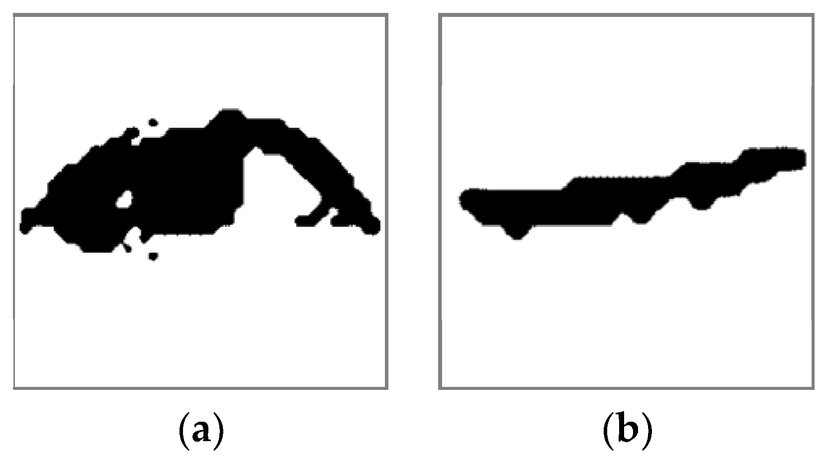
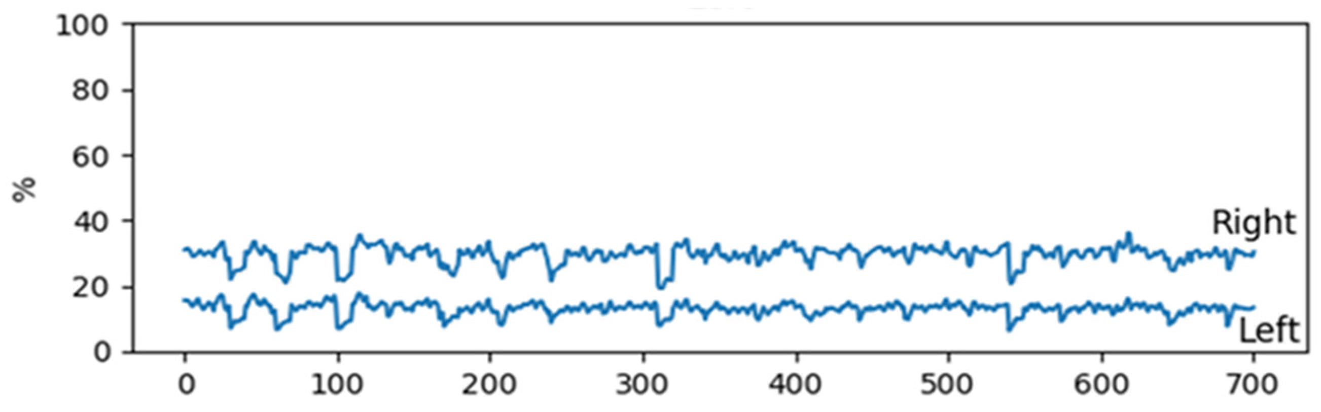
3.2.1. Pixel Ratio

The value of each pixel in the image is represented by 8-bit unsigned characters (value range: 0–255), which can be converted to 0 values by binarization if it is below the threshold, or to the highest value of 255 if it is above the threshold. The image is shown in Figure 7a shows a black-and-white image of the open-eye state and Figure 7b shows a black-and-white image of the closed-eye state. By comparing the two images below it can be seen that the binarised image varies according to the open/closed state of the eye. Thus, if different values are obtained from the two images, the images can be discriminated.
First, acquire the following eye image with a resolution of 64 × 64 pixels. The number of pixels will be 4096. Next, count the number of black pixels in the image. If there are 1024 pixels, the percentage of black pixels is (1024/4096) × 100, or 25%. This ratio was higher when the eye is open and lower when the eye is closed, so when the eye blink, this ratio changes. Figure 8 shows the Data waveform of eye blink image pixel ratio change.

3.2.2. Support Vector Machine

One of the oldest methods used in image classification is the SVM [28]. It is one of the pattern recognition models that uses supervised learning. It differs from ordinary pattern recognition models in that it performs margin maximization and kernel tricks.
A.
Margin maximization
Margin maximization is the shortest distance between the boundary and the data. Figure 9 shows the image of marginal maximization, the idea of margin maximization is to draw the boundary as far away as possible from the data that is closest to the boundary between the two classes.
B.
Mapping of feature space
In encountering nonlinear separation, it is necessary to use kernel tricks in SVM to map the data from the original space to the new space (see Figure 10, mapping 2-dimensional feature space to 3-dimensional feature space), and then the training data are used in the new space to get the learning model using linear methods.
To find a map to feature space, we need to find the inner product φ ( x ) T φ ( y ) on the feature space. The kernel trick allows us to calculate the inner product on the feature space without knowing what the feature space is and what φ is.
Discriminant function:
f ( x ) = s i g n [ i = 1 n a i y i φ ( x i ) T φ ( x ) ]
(a: Weight; y: Label (1 or −1); xi: i-th learning data; x: Input data)
Kernel function:
k ( x , y ) = φ ( x ) T φ ( y )
(Inner product in feature space:   φ ( x ) T φ ( y ) )
Replace the inner product of the discriminant function:
f ( x ) = s i g n [ i = 1 n a i y i k ( x i , x ) ]

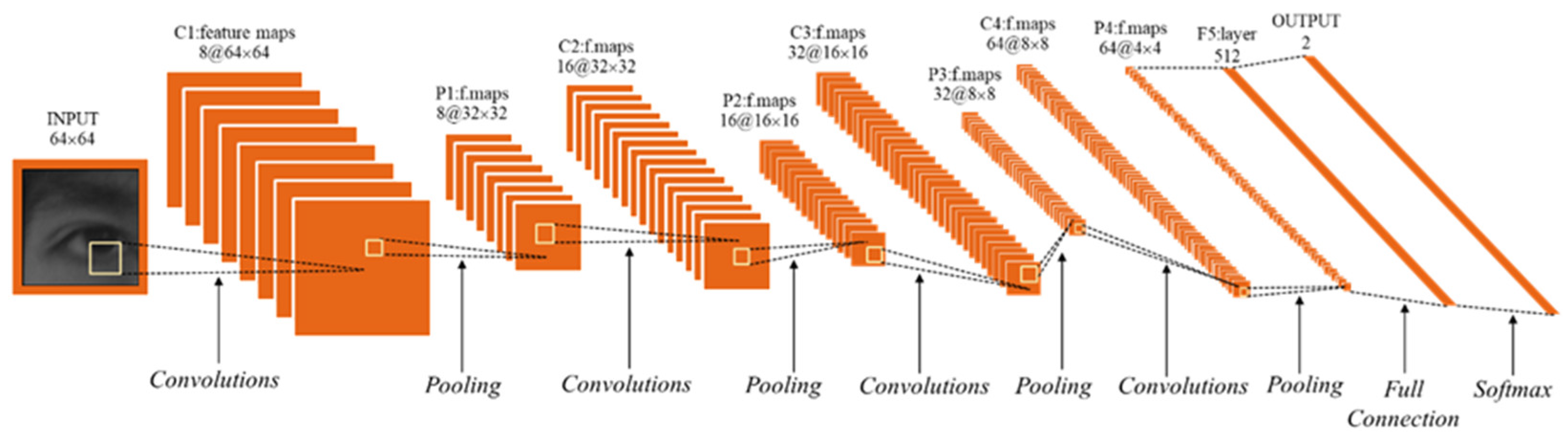
3.2.3. Convolutional Neural Network

The Convolutional Neural Network (CNN) is an important method in the field related to pattern recognition [29]. This research constructed a learning model with CNN and used it to detect blinks of the subject. Figure 11 shows the CNN model constructed in this study. In the constructed CNN model input images of open and closed eyes with a resolution of 64 × 64 were subjected to convolutional operations, the feature values of the input images were extracted, and a recognition model was built based on these feature values and it was applied to the system.
In this experiment, the well-known VGG-16 discriminative model has been used as a reference. Since only two types of images (open-eye and closed-eye) need to be feature extracted and classified, the model was finally reduced from the original 16 layers to 10 layers and the convolutional layers from 13 layers to 8 layers after continuous experiments in order to balance high efficiency and high accuracy. The relevant parameters of each layer are shown in Table 1.

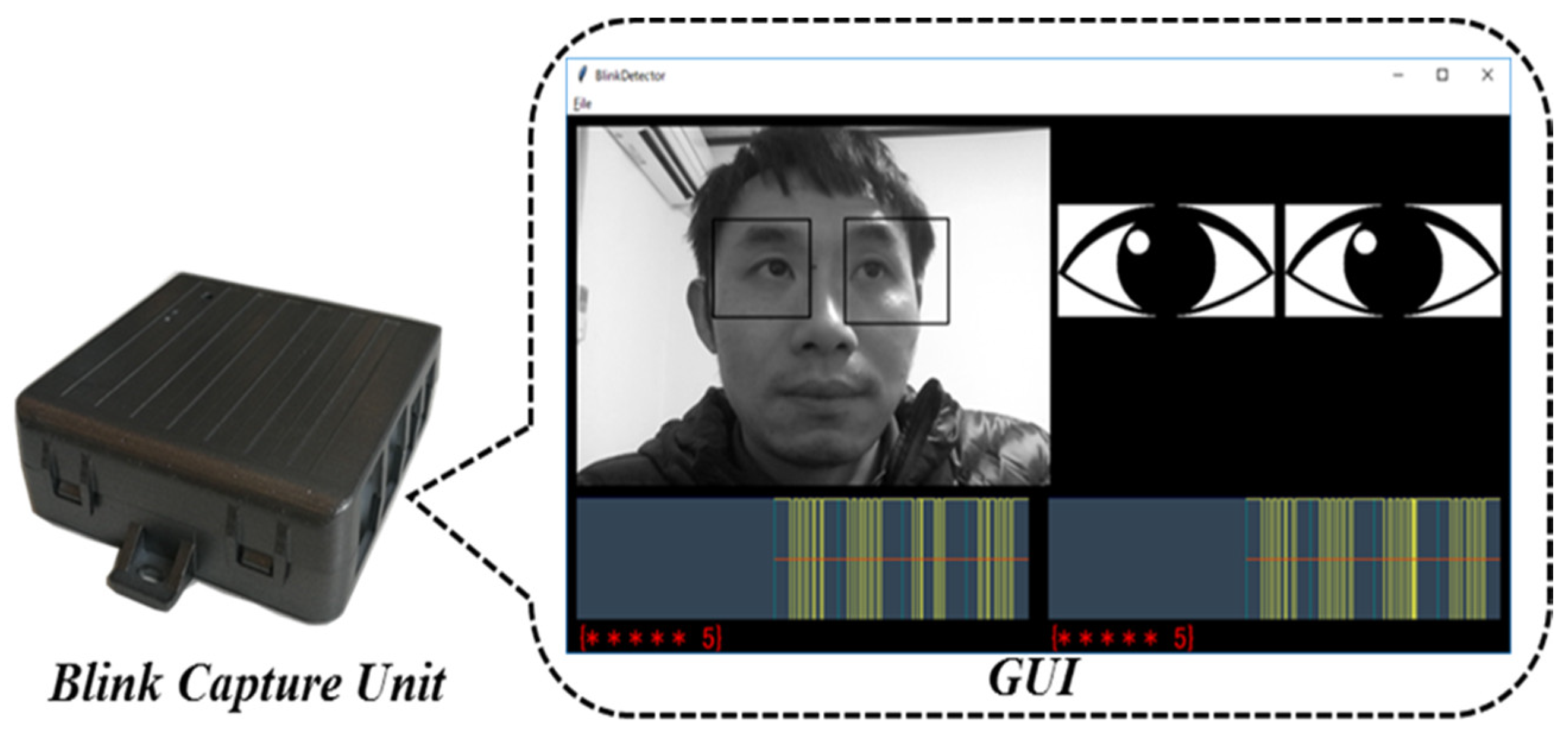
3.2.4. The Eye Blink Detection Device and Its GUI

The graphical user interface of the eye blink detection system is shown in Figure 12, which displays the camera image, the eye status picture area, the eye blink waveform, and the number of consecutive eye blinks by the user. In the upper left area, the camera image was displayed. The eye status picture was displayed in a rectangular area, and the position of the eye area was updated every 10 frames. The two waveforms at the bottom represent the open and closed state of the eye, 1 when the eye is open and 0 when it is closed. The image at the top right shows the state of the eye in the form of an image. The text string at the bottom indicates the number of consecutive eye blinks. The symbol (*) increases with each blink of the eye. The face and eyes object detection module in a face recognition module (Haar Cascade) was used in the program in order to quickly capture the face and locate the eye area, so that the capture frame in the screen always firmly captures both eyes. During the control of the wheelchair, the wheelchair moves forward after the subject eye blinks three times rapidly. After the subject blink once with the right eye, the wheelchair turns right. After the subject blink left once, the wheelchair turns left. After the subject eye blinks four times quickly, the wheelchair moves backward. After the subject eye blinks twice quickly, the wheelchair stops moving.

4. Results and Discussion

4.1. Results of Eye Gaze Direction Recognition Experiments

Figure 13 Comparison of eye images in various states during the experiment. Figure 13a shows the eye image without infrared light irradiation, and Figure 13b shows the image of the eye under infrared illumination. A comparison between the two can be found in Figure 13b, where the pupil contour was more well-defined. Because corneal reflection is a way to detect pupils darker, the iris colours can be compared by separating the infrared light from the optical axis of the eye-tracking camera. Figure 13c shows the eye image after the binarization process. To highlight the binarization changes, the background color was set to blue instead of white. After binarization there were only two colors left in the plot, the next step was to adjust the threshold to make the pupil outline more prominent and obvious in the image.

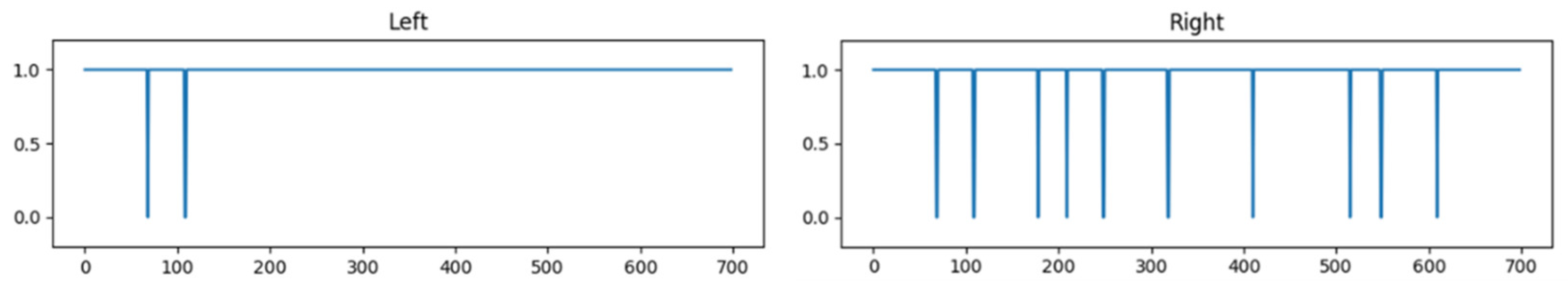
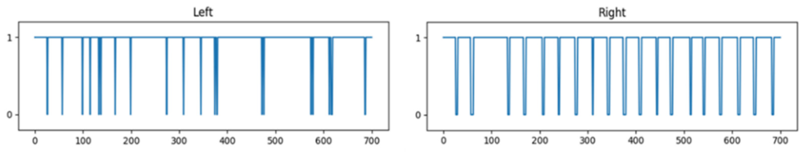
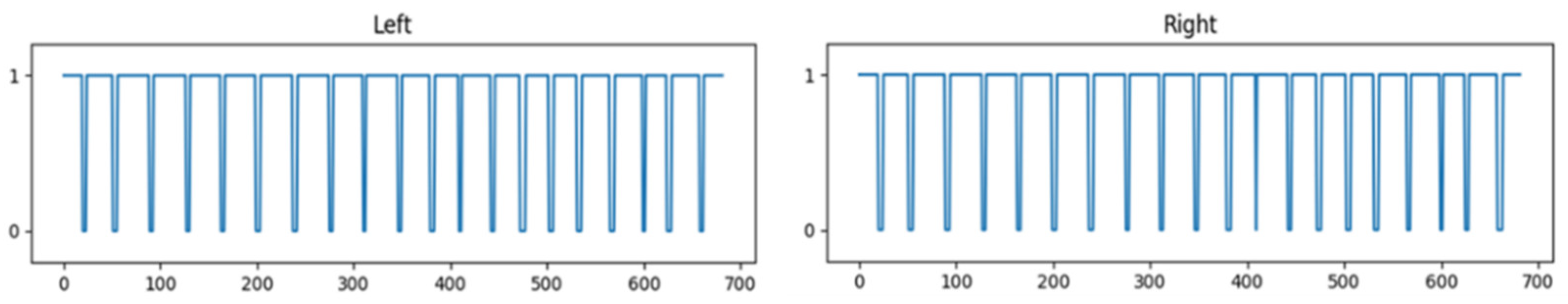
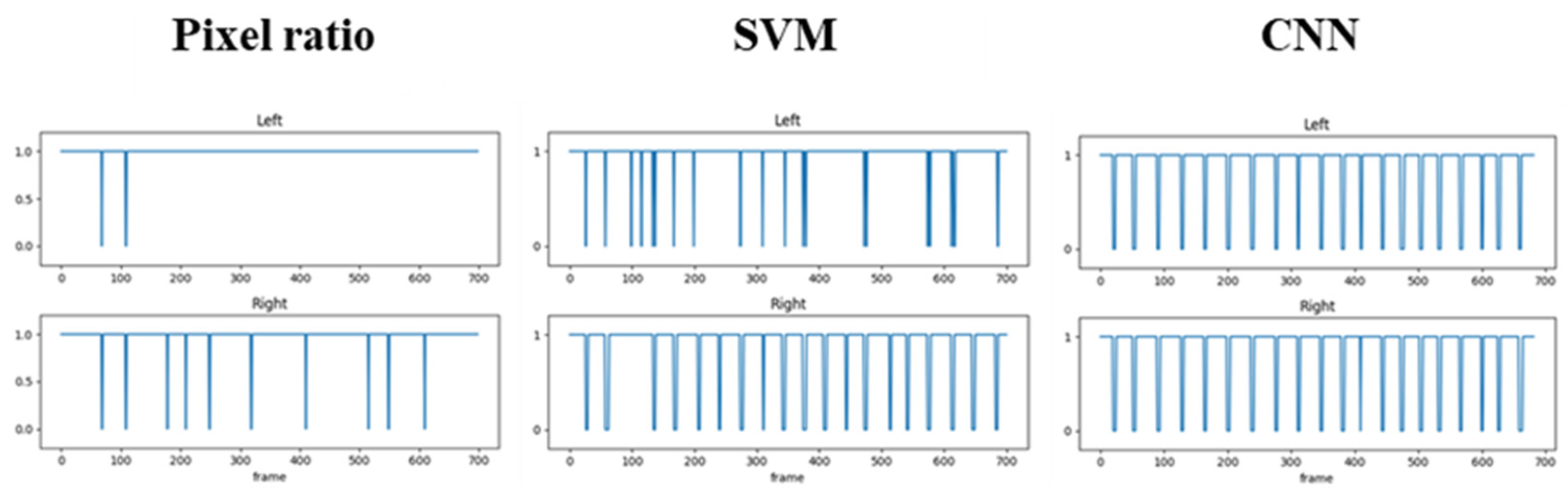
4.2. Eye Blinks Recognition Experimental Results

A.
Pixel Ratio
In this experiment, a 5% change in the pixel ratio was used as an eye blink condition. In addition, some changes can be obtained from the image four frames ago, since the changes were not significant compared to the image one frame ago. Figure 14 shows the judgment waveforms of eye blink detection by the pixel ratio method in this study. During the experiment, a total of 20 blinks was made, only two blinks were detected in the left eye and 10 blinks were detected in the right eye.
B.
Support Vector Machine
In the experiment using the SVM approach to detect eye blink, the testers blinked both eyes the same 20 times. Figure 15 shows judgment waveforms for eye blink detection by SVM, and we can see that 15 blinks were detected in the left eye and 19 blinks were detected in the right eye.
C.
Convolutional Neural Network
Convolution layers can combine different local structures to present more useful features in a region. By convolving the input image, the input image is rendered with more feature maps. Figure 16 shows the convolutional layer feature map data of this study in the experiment. In the first and second layers, there does not seem to be much change. However, in the third layer, the brightness becomes more diversified, indicating that the network can adapt to changes in the brightness of the input image. In the fourth layer, the extracted features were different from those in the previous layers, and the contours were emphasized. Five to six layers show that the contours were greatly emphasized. In the seventh layer, more features were extracted. In the eighth and final layer, the features were extracted to the extent that the original form was no longer visible to the eye.
Figure 17 shows the judgment waveforms of eye blink detection experiment with CNN. The testers performed 20 blinks in both eyes. Based on the data waveform plot it can be seen that all 20 blinks in the left and right eyes were detected by the system.
D.
Comparative Discussion of Results
One hundred experiments were done for each of the three methods of identifying blinks. Table 2 shows the results of the number of detections for 100 blinks, and Figure 18 shows a comparison between the experimental data of the three detection methods. According to the experimental results, the recognition rate using CNN is the highest with 99% accuracy. This indicates that CNN method is still optimal, and the next step is just to adjust each parameter to further improve the accuracy rate. In comparison, the Pixel ratio method is the simplest of the three methods, which does not require the acquisition of human eye images of the subject for learning and runs relatively fast, however, the detection rate is the worst. Although a neural network was built in the SVM method, however it also does not perform image convolution and has the second fastest running speed and has the second lowest detection rate. Finally, the convolutional neural network has the highest detection rate among the three methods, and it is also the most complex of the three methods. In operation, subjects can use different methods depending on the conditions and are able to collect a wider range of data.

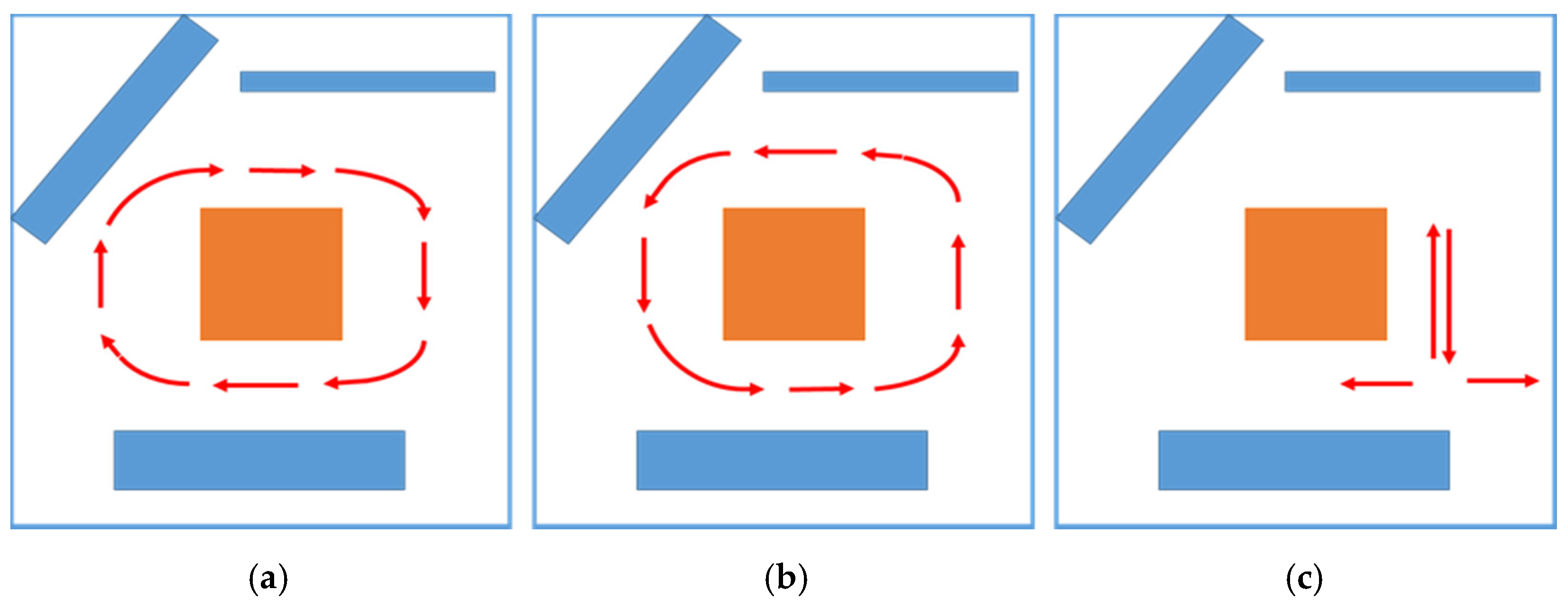
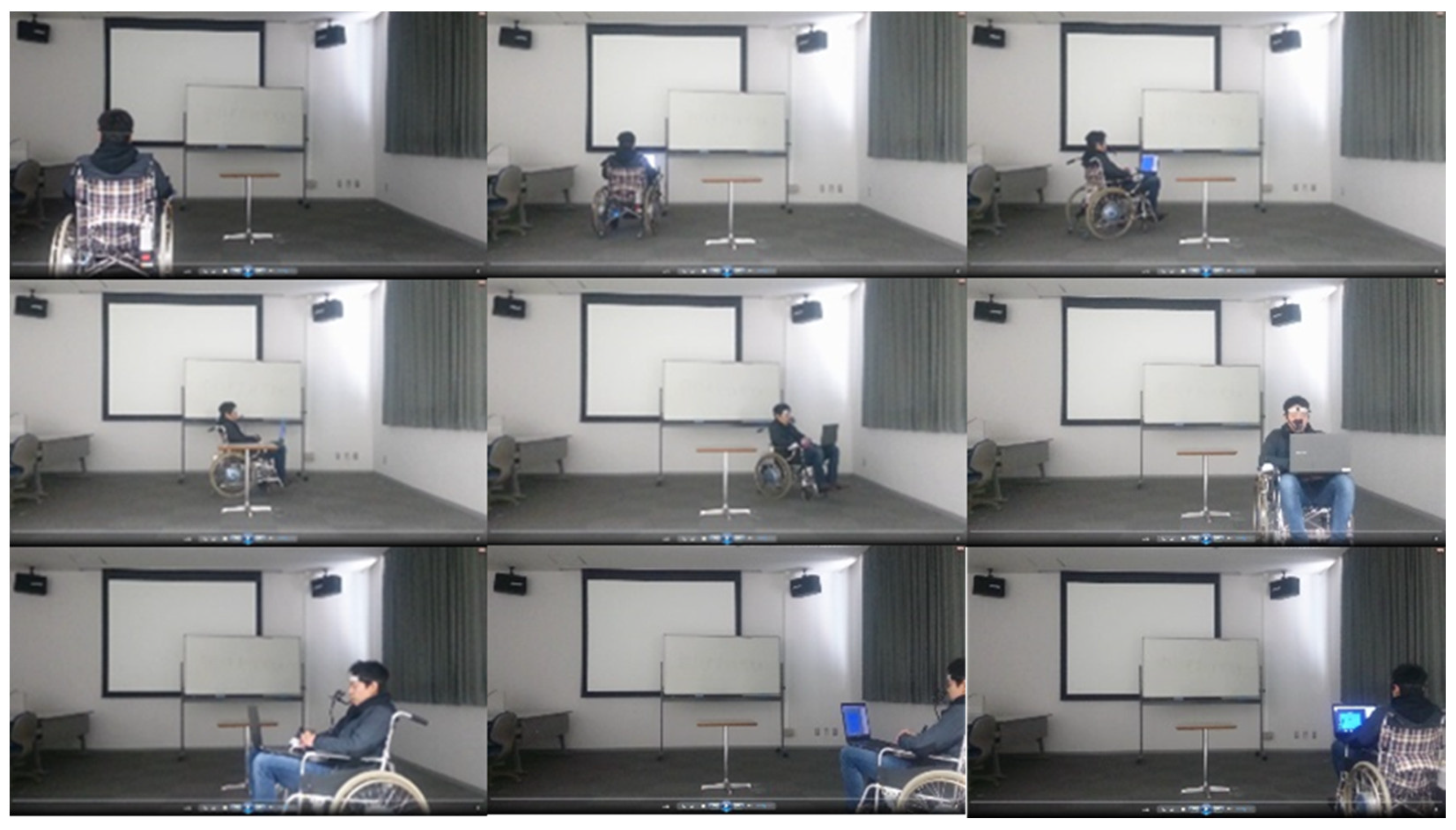
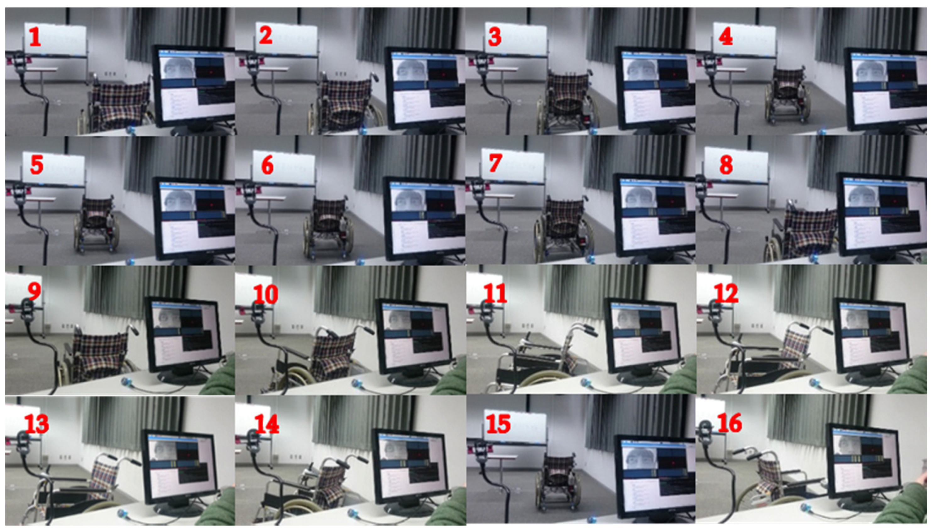
4.3. Drive Experiment Results and Discussion

A.
Drive Experiment Results
Figure 19 shows the roadmap for driving the wheelchair movement during the experience, and some obstacles were set up in the test site in order to increase the difficulty. Twelve subjects controlled the wheelchair movement by eye gaze and eye blink according to the path plan in Figure 19 and each experimented once. All 12 subjects successfully completed the experiment and were able to control their wheelchairs very smoothly to avoid obstacles during the experiment. The shortest time was 2 min and the longest time was 3 min for all 12 subjects to complete the experiment. Figure 19a shows the subjects driving the wheelchair clockwise, and after reaching that end point, the subjects turned around in the same place and moved counterclockwise according to the route in Figure 19b, and completed the whole process after reaching the end point. Figure 19c shows the subject’s remotely controlled wheelchair moving according to the route in the figure. The subject first controls the wheelchair straight ahead to reach the preset point, and then controls the wheelchair backward to the starting point, the subject then controls the wheelchair to turn 90° left, and then 180° right to complete the process.
Figure 20 shows a combined image of experimental data using eye gaze to drive the wheelchair movement, where subjects controlled the wheelchair to move along the route planned in Figure 19a,b. The subject sat in the wheelchair and controlled the wheelchair to move clockwise from the starting point by eye gaze. When the controlled wheelchair reachs the preset end point, it was controlled to stop, turn around in place, and continue to move counterclockwise to the preset end point, thus ending the process.
In the experiment using eye blink controlled wheelchair movement, in order to differentiate the experiments using eye gaze controlled wheelchair movement, the subject sat in front of a monitor with the eye blink detection device placed in front of the eyes, and remotely controlled the wheelchair to move along the route planned in Figure 19c. Figure 21 shows a data set plots of eye blink controlled wheelchair movement experiment. In the figure set, the first row of images (number: 1–4) shows the blink controlled wheelchair moving forward, the second row of images (number: 5–8) shows the blink controlled wheelchair moving backward to its original position, the third row of images (number: 9–12) shows the blink controlled wheelchair turning 90° to turn left, and the fourth row of images (number: 13–16) shows the blink controlled wheelchair turning 180° to turn right. This concludes an experimental cycle.
B.
Discussion of Results
The experimental results show that gaze and eye blink could effectively control the wheelchair to complete the related movements. However, the test subjects had to concentrate on controlling the wheelchair movement throughout the experiment, which was a problem. As a future research topic, the controlled device can provide some feedback to the human body so that it can be alerted in time when the operator is not focused enough.

5. Conclusions

In this paper, the extraction of eye movement information to control relevant mechanical movements was investigated. An eye-movement based HCI system that communicates information to the machine through the human eye was developed in this research. The binarization of the image was used to localize the pupil in this study. Since the difference between the two colors in the eye was apparent, binarization of the pupil image enables the localization of the black pupil, and based on the localization of the pupil, the direction of eye gaze could be determined. Similarly, pixel ratio modelling has been fully used in the eye blink detection. Through operational experiments, it could be confirmed that the eye blink state could be detected, however, the recognition rate could be further improved. Therefore, the machine learning methods SVM and CNN were used for eye blink detection and the accuracy was significantly improved, especially the eye blink detection using CNN method, was tested to reach 99% accuracy.
To further validate these, the system was ported to a power wheelchair. We first modified the hardware of the wheelchair and developed a hardware drive system for the electric wheelchair. This allowed the wheelchair to receive commands from the subject through eye movements. In the experiment, the subject sat in the wheelchair to control its movement, or controls the wheelchair movement remotely. The wheelchair was controlled and followed a set route, successfully avoiding obstacles along the way to the end point, and was tested repeatedly and successfully. The experiments proved that the method of obtaining information expressed by human eyes through image parsing and machine learning has been effective. Future research can optimize the model on this basis to obtain more information conveyed by the human eye, for example, the fatigue level and mental state of a person can be judged by the human eye.

Author Contributions

Conceptualization, W.L. and D.J.; Data curation, W.L., J.C. and D.J.; Formal analysis, W.L.; Funding acquisition, D.J.; Investigation, W.L.; Methodology, W.L.; Project administration, D.J.; Resources, D.J.; Software, W.L.; Supervision, J.C. and D.J.; Validation, J.C., K.I. and D.J.; Writing—original draft, W.L.; Writing—review & editing, J.C. and D.J. All authors have read and agreed to the published version of the manuscript.

Funding

This research received no external funding.

Informed Consent Statement

Informed consent was obtained from all subjects and from their legal guardians involved in the study.

Data Availability Statement

All gathered data is reported in the Results section of this paper and will be available on request and plan to make it online.

Conflicts of Interest

The authors declare no conflict of interest.

References

  1. Hoc, J.M. From human-machine interaction to human-machine cooperation. Ergonomics 2000, 43, 833–843. [Google Scholar] [CrossRef] [PubMed]
  2. Memo, A.; Zanuttigh, P. Head-mounted gesture controlled interface for human-computer interaction. Multimed. Tools Appl. 2018, 77, 27–53. [Google Scholar] [CrossRef]
  3. Drewes, H.; Schmidt, A. IFIP Conference on Human-Computer Interaction, Interacting with the Computer Using Gaze Gestures; Springer: Berlin/Heidelberg, Germany, 2007; pp. 475–488. [Google Scholar]
  4. Pfeuffer, K.; Alexander, J.; Chong, M.K.; Gellersen, H. Gaze-touch: Combining gaze with multi-touch for interaction on the same surface. In Proceedings of the 27th Annual ACM Symposium on User Interface Software and Technology, Honolulu, HI, USA, 5–8 October 2014; ACM: New York, NY, USA, 2014. [Google Scholar]
  5. Bickenbach, J.E.; Chatterji, S.; Badley, E.M.; Üstün, T.B. Models of disablement, universalism and the international classification of impairments, disabilities and handicaps. Soc. Sci. Med. 1999, 48, 1173–1187. [Google Scholar] [CrossRef]
  6. Sorbello, R.; Tramonte, S.; Giardina, M.E.; La Bella, V.; Spataro, R.; Allison, B.; Guger, C.; Chella, A. A Human–Humanoid Interaction Through the Use of BCI for Locked-In ALS Patients Using Neuro-Biological Feedback Fusion. IEEE Trans. Neural Syst. Rehabil. Eng. 2018, 26, 487–497. [Google Scholar] [CrossRef] [PubMed]
  7. Rupom, A.I.; Patwary, A.B. P300 Speller Based ALS Detection Using Daubechies Wavelet Transform in Electroencephalograph. In Proceedings of the International Conference on Electrical, Computer and Communication Engineering, Cox’s Bazar, Bangladesh, 7–9 February 2019. [Google Scholar]
  8. Korovesis, N.; Kandris, D.; Koulouras, G.; Alexandridis, A. Robot motion control via an EEG-based brain--computer interface by using neural networks and alpha brainwaves. Electronics 2019, 8, 1387. [Google Scholar] [CrossRef] [Green Version]
  9. Deligani, R.J.; Hosni, S.I.; Borgheai, S.B.; McLinden, J.; Zisk, A.H.; Mankodiya, K.; Shahriari, Y. Electrical and Hemodynamic Neural Functions in People With ALS: An EEG-fNIRS Resting-State Study. IEEE Trans. Neural Syst. Rehabil. Eng. 2020, 28, 3129–3139. [Google Scholar] [CrossRef] [PubMed]
  10. Chowdhury, T.T.; Fattah, S.A.; Shahnaz, C. ALS Detection Based on T-Location Scale Statistical Modeling of the DWT Coefficients of EMG Signals. In Proceedings of the IEEE International Conference on Biomedical Engineering, Computer and Information Technology for Health (BECITHCON), Dhaka, Bangladesh, 1 December 2019. [Google Scholar]
  11. Carrasquilla-Batista, A.; Quiros-Espinoza, K.; Gomez-Carrasquilla, C. An Internet of Things (IoT) application to control a wheelchair through EEG signal processing. In Proceedings of the 2017 International Symposium on Wearable Robotics and Rehabilitation (WeRob), Houston, TX, USA, 5–8 November 2017. [Google Scholar]
  12. Larson, A.; Herrera, J.; George, K.; Matthews, A. Electrooculography based electronic communication device for individuals with ALS. In Proceedings of the IEEE Sensors Applications Symposium (SAS), Glassboro, NJ, USA, 11–13 March 2019. [Google Scholar]
  13. Hansen, D.W.; Ji, Q. In the Eye of the Beholder: A Survey of Models for Eyes and Gaze. IEEE Trans. Pattern Anal. Mach. Intell. 2010, 32, 478–500. [Google Scholar] [CrossRef] [PubMed]
  14. Hutchinson, T.E.; White, K.P.; Martin, W.N.; Reichert, K.C.; Frey, L.A. Human-computer interaction using eye-gaze input. IEEE Trans. Syst. Man Cybern. 1989, 19, 1527–1534. [Google Scholar] [CrossRef]
  15. Shinde, S.; Kumar, S.; Johri, P. A Review: Eye Tracking Interface with Embedded System & IOT. In Proceedings of the International Conference on Computing Power and Communication Technologies (GUCON), Greater Noida, India, 28–29 September 2018. [Google Scholar]
  16. Wanluk, N.; Visitsattapongse, S.; Juhong, A.; Pintavirooj, C. Smart wheelchair based on eye tracking. In Proceedings of the 9th Biomedical Engineering International Conference (BMEiCON), Laung Prabang, Laos, 7–9 December 2016. [Google Scholar]
  17. Li, X.; Wee, W.G. An efficient method for eye tracking and eye-gazed FOV estimation. In Proceedings of the 16th IEEE International Conference on Image Processing (ICIP), Cairo, Egypt, 7 November 2009. [Google Scholar]
  18. Arai, K.; Mardiyanto, R. Eyes Based Eletric WheelChair Control System. Int. J. Adv. Comput. Sci. Appl. 2011, 2, 98–105. [Google Scholar]
  19. Araujo, J.M.; Zhang, G.; Hansen, J.P.P.; Puthusserypady, S. Exploring Eye-Gaze Wheelchair Control. In ACM Symposium on Eye Tracking Research and Applications; ACM: New York, NY, USA, 2020. [Google Scholar]
  20. Hansen, J.P.; Trudslev, A.K.; Harild, S.A.; Alapetite, A.; Minakata, K. Providing access to VR through a wheelchair. In Extended Abstracts of the 2019 CHI Conference on Human Factors in Computing Systems; ACM: New York, NY, USA, 2019. [Google Scholar]
  21. Pfeuffer, K.; Vidal, M.; Turner, J.; Bulling, A.; Gellersen, H. Pursuit calibration: Making gaze calibration less tedious and more flexible. In Proceedings of the 26th Annual ACM Symposium on User Interface Software and Technology, Tokyo, Japan, 16–19 October 2013; ACM: New York, NY, USA, 2013. [Google Scholar]
  22. Purwantoa, D.; Mardiyanto, R.; Arai, K. Electric wheelchair control with gaze direction and eye blinking. Artif. Life Robot. 2009, 14, 397–400. [Google Scholar] [CrossRef]
  23. Varela, M. Raw eeg signal processing for bci control based on voluntary eye blinks. In Proceedings of the 2015 IEEE Thirty Fifth Central American and Panama Convention, Tegucigalpa, Honduras, 11–13 November 2015. [Google Scholar]
  24. Gomez-Carrasquilla, C.; Quiros-Espinoza, K.; Carrasquilla-Batista, A. Wheelchair control through eye blinking and IoT platform. In Proceedings of the 2020 IEEE 11th Latin American Symposium on Circuits Systems, San Jose, Costa Rica, 28 February 2020. [Google Scholar]
  25. Ren, P.; Ma, X.; Lai, W.; Zhang, M.; Liu, S.; Wang, Y.; Li, M.; Ma, D.; Dong, Y.; He, Y.; et al. Comparison of the Use of Blink Rate and Blink Rate Variability for Mental State Recognition. IEEE Trans. Neural Syst. Rehabil. Eng. 2019, 27, 867–875. [Google Scholar] [CrossRef] [PubMed]
  26. El Naqa, I.; Murphy, M.J. Machine learning in radiation oncology. In What is Machine Learning; Springer: Cham, Switzerland, 2005; pp. 3–11. [Google Scholar]
  27. Hu, S. Document image watermarking algorithm based on neighborhood pixel ratio. Proceedings. (ICASSP ‘05). In Proceedings of the IEEE International Conference on Acoustics, Speech, and Signal Processing, Philadelphia, PA, USA, 23 March 2005. [Google Scholar]
  28. Suthaharan, S. Machine learning models and algorithms for big data classification. In Support Vector Machine; Springer: Boston, MA, USA, 2016; pp. 207–235. [Google Scholar]
  29. Albawi, S.; Mohammed, T.A.; Al-Zawi, S. Understanding of a convolutional neural network. In Proceedings of the International Conference on Engineering and Technology, Antalya, Turkey, 21–23 August 2017. [Google Scholar]
  30. Choi, K.; Cichocki, A. Control of a Wheelchair by Motor Imagery in Real Time. In International Conference on Intelligent Data Engineering and Automated Learning; Springer: Berlin/Heidelberg, Germany, 2008; pp. 330–337. [Google Scholar]
  31. Mahmoud, A.; Hamoud, M.; Ahmad, A.M.; Ahmad, A.S. Controlling a Wheelchair Using Human-Computer Interaction. Int. J. Sci. Res. 2018, 7, 681–686. [Google Scholar]
  32. Pande, V.V.; Ubale, N.S.; Masurkar, D.P.; Ingole, N.R.; Mane, P.P. Hand Gesture Based Wheelchair Movement Control for Disabled Person Using MEMS. J. Eng. Res. Appl. 2014, 4, 152–158. [Google Scholar]
  33. Chen, Y.L.; Chen, S.C.; Chen, W.L.; Lin, J.F. A head orientated wheelchair for people with disabilities. Disabil. Rehabil. 2003, 25, 249–253. [Google Scholar] [CrossRef] [PubMed]
  34. Mandel, C.; Luth, T. Navigating a smart wheelchair with a braincomputer interface interpreting steady-state visual evoked potentials. In Proceedings of the 2009 IEEE/RSJ International Conference, St. Louis, MO, USA, 10 October 2009. [Google Scholar]
  35. Lund, M.E.; Christiensen, H.V.; Caltenco, H.A.; Lontis, E.R.; Bentsen, B.; Andreasen Struijk, L.N.S. Inductive tongue control of powered wheelchairs. In Proceedings of the 2010 Annual International Conference of the IEEE Engineering in Medicine and Biology, Buenos Aires, Argentina, 1–4 September 2010. [Google Scholar]
  36. Singer, C.C.; Hartmann, B. See-Thru: Towards Minimally Obstructive Eye-Controlled Wheelchair Interfaces. In Proceedings of the 21st International ACM SIGACCESS Conference on Computers and Accessibility, Pittsburgh, PA, USA, 28–30 October 2019; ACM: New York, NY, USA, 2019. [Google Scholar]
Figure 1. Schematic diagram of the HCI system for eye state recognition.
Mti 05 00050 g001
Figure 2. Modified electric wheelchair hardware display image.
Mti 05 00050 g002
Figure 3. Circuit schematic of the driver circuit board.
Mti 05 00050 g003
Figure 4. Diagram of corneal reflection eye tracking technology.
Mti 05 00050 g004
Figure 5. Flow chart of eyeball tracking technology.
Mti 05 00050 g005
Figure 6. The command chart corresponding to the eye gazes area.
Mti 05 00050 g006
Figure 7. Binarized black and white images of the eye with the eye open and closed. (a) Open eye binary image; (b) Close eye binary image.
Mti 05 00050 g007
Figure 8. Data waveform of eye blink image pixel ratio change.
Mti 05 00050 g008
Figure 9. Schematic diagram of margin maximization.
Mti 05 00050 g009
Figure 10. The 2D feature space is mapped to the 3D feature space.
Mti 05 00050 g010
Figure 11. The structure of CNN that has been built.
Mti 05 00050 g011
Figure 12. Diagram of blink detection device and its graphical user interface. The red symbol (*) in the interface increases with each blink of the eye.
Mti 05 00050 g012
Figure 13. Comparison of eye images during the experiment. (a) The eye image without infrared light irradiation; (b) The image of the eye under infrared illumination; (c) The eye image after the binarization process.
Mti 05 00050 g013
Figure 14. Judgment waveforms for eye blink detection by pixel ratio. Left: Blink judgement waveform in the left eye; Right: Blink judgement waveform in the right eye.
Mti 05 00050 g014
Figure 15. Judgment waveforms for eye blink detection by SVM. Left: Blink judgement waveform in the left eye; Right: Blink judgement waveform in the right eye.
Mti 05 00050 g015
Figure 16. The feature map of convolution layer.
Mti 05 00050 g016
Figure 17. Judgment waveforms for eye blink detection of CNN. Left: Blink judgement waveform in the left eye; Right: Blink judgement waveform in the right eye.
Mti 05 00050 g017
Figure 18. Comparison among the experimental data of the three detection methods. Pixel ratio: Blink judgement waveform using Pixel ratio; SVM: Blink judgement waveform using SVM; CNN: Blink judgement waveform using CNN.
Mti 05 00050 g018
Figure 19. Drive wheelchair movement route planning map. (a) Clockwise driving route; (b) Counter-clockwise driving route; (c) Remote control of driving routes.
Mti 05 00050 g019
Figure 20. Eye gaze direction control wheelchair movement experiment.
Mti 05 00050 g020
Figure 21. Eye blink control wheelchair travel experiment.
Mti 05 00050 g021
Table 1. Relevant parameters of each layer.
Layer NameLayer TypeRelate Parameters
Conv1_1convolution3 × 3, 8, relu, stride1
Conv1_2convolution3 × 3, 8, relu, stride1
Pool1Pooling2 × 2, 8, max pool, stride2
Conv2_1convolution3 × 3, 16, relu, stride1
Conv2_2convolution3 × 3, 16, relu, stride1
Pool2Pooling2 × 2, 16, max pool, stride2
Conv3_1convolution3 × 3, 32, relu, stride1
Conv3_2convolution3 × 3, 32, relu, stride1
Pool3Pooling2 × 2, 32, max pool, stride2
Conv4_1convolution3 × 3, 64, relu, stride1
Conv4_2convolution3 × 3,64, relu, stride1
Pool4Pooling2 × 2, 64, max pool, stride2
Fuc1Fully-connected512, sigmoid
DropDropoutdropout-ratio 0.5
Fuc2Fully-connected2, softmax
Table 2. Number of detections per 100 blinks.
MethodsDetection CountUndetected CountFalse Positives Count
pixel ratio28720
SVM742611
CNN9910
Publisher’s Note: MDPI stays neutral with regard to jurisdictional claims in published maps and institutional affiliations.

