Single Crystal Diffuse Neutron Scattering


1
Research School of Chemistry, Australian National University, Canberra, ACT 2601, Australia
2
Neutron Scattering Division, Oak Ridge National Laboratory, Oak Ridge, TN 37831, USA
*
Author to whom correspondence should be addressed.
Quantum Beam Sci. 2018, 2(1), 2; https://doi.org/10.3390/qubs2010002
Submission received: 30 November 2017
/
Revised: 5 January 2018
/
Accepted: 8 January 2018
/
Published: 11 January 2018
(This article belongs to the Special Issue Selected Reviews in Quantum Beam Science)
Abstract
:Diffuse neutron scattering has become a valuable tool for investigating local structure in materials ranging from organic molecular crystals containing only light atoms to piezo-ceramics that frequently contain heavy elements. Although neutron sources will never be able to compete with X-rays in terms of the available flux the special properties of neutrons, viz. the ability to explore inelastic scattering events, the fact that scattering lengths do not vary systematically with atomic number and their ability to scatter from magnetic moments, provides strong motivation for developing neutron diffuse scattering methods. In this paper, we compare three different instruments that have been used by us to collect neutron diffuse scattering data. Two of these are on a spallation source and one on a reactor source.
1. Introduction
Bragg scattering, which is used in conventional crystallography, gives only information about the average crystal structure. Diffuse scattering from single crystals, on the other hand, is a prime source of local structural information. There is now a wealth of evidence to show that the more local structure is investigated the more we are obliged to reassess our understanding of crystalline structure and behaviour [1].
It is important to realize that the average structure is just that: the average of many different local structures. As a material’s properties often depend on this local structure it is important to understand of what different local structures the average is comprised. Developing, optimizing and critically assessing the tools that we have available to uncover local structure in crystals is now a vital part of crystallography [1]. Although X-ray diffuse scattering is of prime importance and is well documented [2,3], diffuse neutron scattering can play an important role too, especially in view of the unique properties of neutrons—their ability to explore inelastic scattering events, the fact that scattering lengths do not vary systematically with atomic number and their ability to scatter from magnetic moments.
Since diffuse scattering intensities are typically several orders of magnitude lower than Bragg peak intensities it might be supposed that obtaining diffuse scattering data using neutrons is simply not a viable proposition. The neutron fluxes available at the best neutron facilities in the world are very low in comparison to the photon fluxes available for X-ray sources. For example the neutron flux on SXD [4] at ISIS (Didcot, UK) is neutrons per s per mm whereas the X-ray flux at the 1-ID beamline at APS is photons per s per mm [5]. Note that the X-ray flux given is the flux at the sample after monochromatisation. With the monochromator selecting energies with a resolution this means a large fraction of the available photons are not utilized. In contrast, for experiments at a spallation neutron source, it is possible to use the whole spectrum of incident neutron wavelengths since their contribution to the scattering can be separated by time-of-flight (TOF) spectroscopy. If this is coupled with the use of extensive detector banks that cover a large fraction of the scattering solid angle a large enough enhancement factor relative to the X-ray case is obtained such that recording diffuse scattering can become quite viable for a suitably sized sample. A typical sample size recommended for SXD is mm while for the synchrotron a size of mm is more typical.
Nuclear reactors are traditional “steady state” neutron sources and have been used for diffraction experiments since about 1950. Wilson [6] has given an account of the development and relative merits of reactor versus spallation sources. The high-flux reactor-based Institut Laue-Langevin (ILL) (Grenoble, France) is an international research centre that is still at the leading edge of neutron science and technology despite having been established in 1972. Technological limitations as well as political issues associated with building more powerful reactors have set limits on possible neutron production from reactors and further dramatic increases in flux are unlikely. Accelerator driven sources are not subject to the same technological or political constraints and these can potentially offer increasingly higher fluxes into the future. Since the experiments on SXD described below in Section 2, which were carried out when the ISIS facility was the most intense spallation source in the world, other more powerful spallation sources have already come on stream (this includes the spallation neutron source (SNS) at Oak Ridge National Laboratory, (Oak Ridge, TN, USA) where the new CORELLI instrument described in Section 3 is located). For diffuse scattering studies a reactor source is, moreover, not ideal since, in order to survey reciprocal space, either a monochromator has to be used or alternatively a single aperture chopper employed to allow TOF analysis as in the spallation neutron case. Either of these scenarios means that a large proportion of the neutrons generated in a reactor are discarded. Despite this, with a suitably sized sample, useful diffuse scattering data can be obtained at a reactor and an example of this is described in Section 4.
In this paper we describe experiments on three different instruments that are available for neutron scattering experiments and that have contributed towards making diffuse neutron scattering a viable and valuable research tool. In Section 2 and Section 3 below we compare measurements made on the molecular material d-benzil, C14D10O2, using SXD at the ISIS spallation neutron source [7] with more recent measurements made at the SNS spallation source using the dedicated diffuse scattering instrument CORELLI [8]. For comparison in Section 4 we show what results can be achieved at a reactor source as typified by measurements made on lead zinc niobate, (PZN), using the high intensity powder diffraction instrument Wombat at the Open Pool Australian Lightwater reactor (OPAL) (Lucas Heights, Australia) [9]. Before proceeding it is useful to recall here the relationships that exist between various quantities pertinent to the discussion. The neutron wavelength is given by , where h is Planck’s constant, m is the neutron mass and v is its velocity. The neutron energy is given by . The velocity may be measured by the TOF for the neutron to reach the detector located at a distance , where . For a more complete discussion see Copley and Udovic [10].
2. Spallation Neutrons I —SXD Single Crystal Instrument at the ISIS Facility
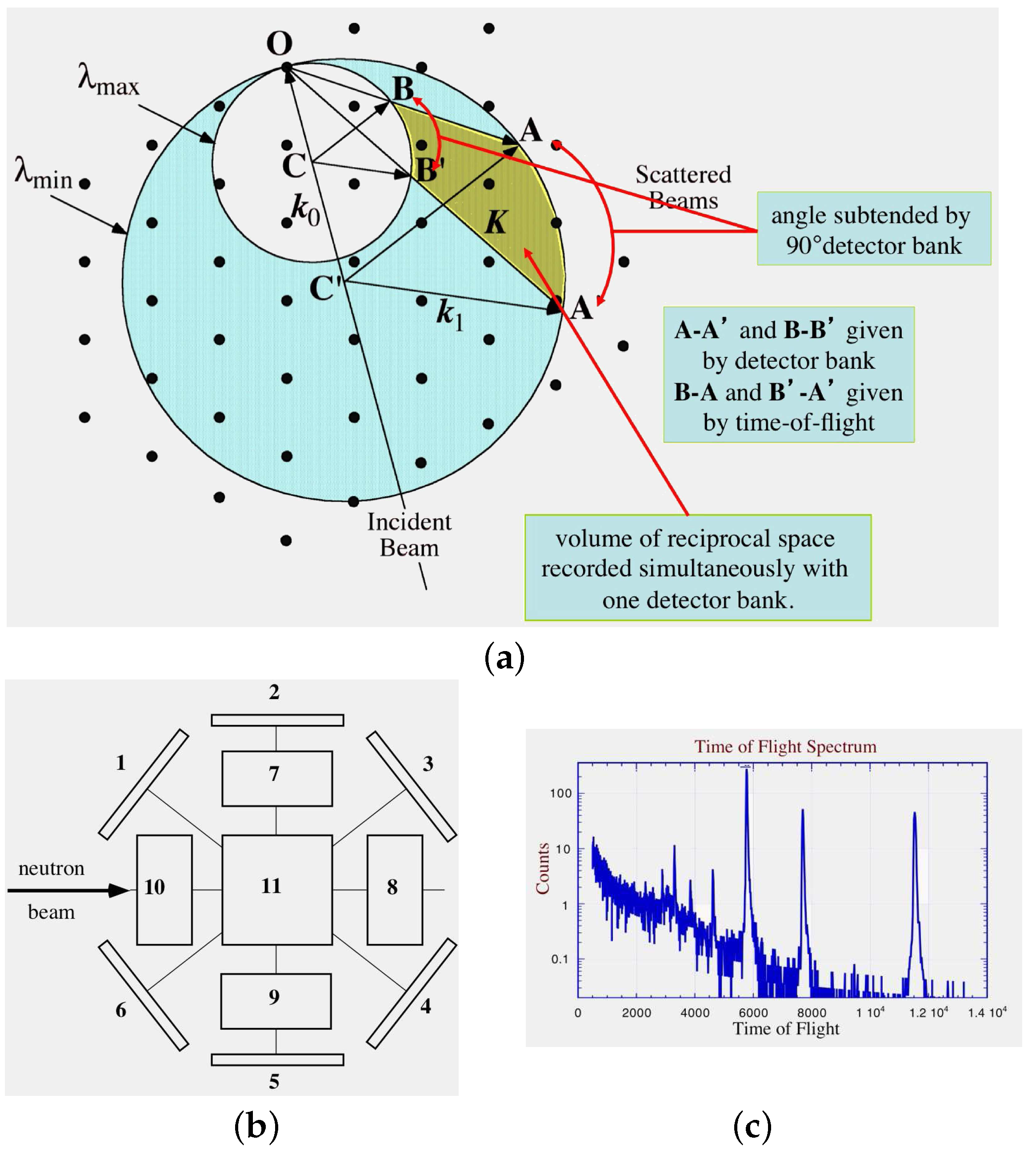
Welberry et al. [7] have recorded diffuse scattering from the molecular crystal d-benzil, C14D10O2, using the SXD single crystal diffractometer at the ISIS Facility of the Rutherford Appleton laboratory. The experimental details and resulting diffuse scattering data for this example are illustrated in Figure 1 and Figure 2. Figure 1a shows the diffraction geometry for a single stationary crystal setting and for a single detector bank whose centre is positioned at the scattering angle 2 = . The figure is drawn to show how the neutrons are scattered in directions emanating from the centres of the Ewald spheres towards the detector bank for the two cases corresponding to the minimum and maximum wavelength present in the incident beam. The radii of the two spheres shown were chosen for clarity. In practice the value of is around smaller than . Figure 1b shows the arrangement of detector banks on SXD. There are 11 detectors each of which has pixels with each pixel recording a complete TOF spectrum. The blue shaded area in Figure 1a shows that region of the reciprocal lattice that lies within the Ewald spheres corresponding to the maximum () and minimum () wavelengths and covers all points that are scattering simultaneously for this crystal setting. The green shaded area covers all reciprocal points that give rise to scattering that is directed towards the detector bank (detector 5 in this case).
The combination of the two-dimensional nature of the detectors and the TOF spectrum allows a large 3D region of reciprocal space to be recorded at any stationary position of the crystal sample. To get a complete mapping of reciprocal space a number of exposures are required with the crystal rotated by an angle about the vertical axis (normal to the plane of the paper in Figure 1b). Since the equatorial detectors subtend an angle of of (i.e., of ) an increment of in is required to ensure successive exposures give an unbroken mapping of reciprocal space. In practice is generally incremented by to allow some overlap. In the time available three complete such exposures were made and a fourth partially completed (approximately half the time of the others). The length of each full exposure (typically ∼18 h) was determined by monitoring the number of microamps of the beam current. The data presented in Figure 2 were selected from a complete 3D set of data that was collected in just over three days in total. The benzil crystal used to record the data shown in Figure 2 measured mm.
Figure 2 shows reciprocal lattice plots of diffuse scattering in the section of benzil at 150 K recorded on the SXD instrument. Figure 2a shows data from a single detector (detector 1 in Figure 1b) for a single crystal orientation setting. Figure 2b shows the coverage obtained using the 6 equatorial detectors (Nos. ) for a single crystal orientation setting. For comparison Figure 2c shows the coverage given by a single detector but using 3 crystal settings. These 3 settings corresponded to successive rotations of the sample by ∼. Since a d-benzil crystal has m symmetry these three settings are sufficient to provide complete coverage of the asymmetric unit of data. Figure 2d shows a complete reciprocal section of data in which 3 crystal orientations have been used together with four detector banks and with m symmetry averaging applied. This gives better signal to noise and a smoother scattering pattern. For Figure 2a–d the data extends out to a maximum Q = 4 of 15 Å. Figure 2e,f highlight the data at lower values of Q. In both Figure 2e,f three crystal orientations and symmetry averaging were used with a single detector. For Figure 2e detector 1 was used while for Figure 2f detector 3 was used.
For a given Q the high-angle and low-angle detectors measure the data with longer and shorter wavelengths and this impacts on the way the inelastic features are sampled.
Thus there is a marked contrast between data shown in Figure 2f,e. In Figure 2f there are prominent diffuse lines forming a hexagon shape near the centre of the pattern (and other diffuse lines at higher Q) while these have largely been dispersed in Figure 2e. The diffuse lines arise from a low-energy phonon mode in benzil corresponding to a shearing motion of the molecular rows and columns. Since the energy of this mode is ∼1 meV, which is small compared to the energies of the neutrons detected in detector bank 3, the scattering here is almost elastic and the pattern looks very similar to what is observed with X-rays. For Figure 2e the neutron energies are much lower and these scatter quite inelastically with the phonon mode so that the intensity in the diffuse line is dispersed. For further details see reference [7]. Since the energy (or wavelength) of each neutron recorded is known from its TOF the scattering pattern can be explored further by, for example, binning only those neutrons within a certain energy range, hence tuning the range of energy transfers over which is integrated.
3. Spallation Neutrons II—CORELLI Cross Correlation Spectrometer at SNS
While SXD uses the spallation pulse itself to allow time-of-flight resolution of the energy of each scattered neutron the CORELLI instrument at SNS additionally uses a statistical chopper together with a cross correlation analysis technique to allow discrimination of elastic and inelastic scattering events. Use of cross correlation techniques in diffuse scattering studies were pioneered many years ago [11]. The operation of this cross correlation method as used in CORELLI has been described by a number of authors [8,12,13,14]. We here give a brief description based on these sources.
The chopper (see Figure 3a) comprises 127 transparent and 128 opaque apertures (sectors) positioned in a random sequence around a disc. The chopper is positioned m downstream from the target so the initial spallation pulses have become quite spread out by the time they reach the chopper, with the high energy neutrons arriving first and lower energies later. Each transparent aperture in the chopper then acts as a secondary pulse source of virtually monochromatic neutrons of an energy and intensity dependent on this initial TOF and a phase offset due to its sequence around the disc. For the cross-correlation method described below it is necessary to sample the total TOF spectrum for all possible offsets with the same probability and this is easily and almost instantaneously obtained by rotating the chopper asynchronously with the source. The current maximum chopper rotation speed is rather less than 300 Hz (18,000 rpm). Since a speed of exactly 300 Hz would result in each chopper aperture producing a secondary pulse exactly 5 times per primary pulse cycle (60 Hz), the rotation speed must be reduced somewhat to achieve the desired asynchrony.
The transmitted neutrons then go forward to scatter from the sample which is located a short distance ( m) downstream from the chopper. This is shown schematically in Figure 3b. The neutrons that are able to pass through the chopper are scattered from the sample with probability and arrive at a detector pixel at a time t after the initial pulse. The intensity recorded in a single pixel of the detector as a function of the total TOF is seen to be the sum of all such scattering events and may be expressed as in Equation (1) (see reference [12]). The time at which the neutron beam transits the first sector of the chopper is . Figure 3b also shows that at the sample neutrons may be scattered either elastically (green line) or inelastically (red and blue lines) as their energy is increased or decreased (e.g., by the creation or annihilation of phonons). Successive apertures act identically but with neutrons of a different energy and intensity where is a time shift dependent on the sector number. The intensity recorded at the detector for a given total TOF t is then the sum of over all possible scattering events , modulated by the chopper modulation function :
Here, is the scattering function for incident neutrons with phase offset and total time-of-flight, t. is the chopper modulation function, denotes the start of the modulation sequence with respect to the source pulse, is the neutron flux for the corresponding incident energy, and is the background at the detector that is uncorrelated with the chopper.
Rozenkrantz and Osborn [8] have shown that if the cross-correlation is formed between the detector intensity and the chopper modulation sequence this yields the scattering function , where and t are the incident and scattered times of flight respectively. This relies first of all on the data being recorded for a sufficient time that all possible phase offsets occur with equal probability and secondly that the pseudorandom modulation sequence, , is characterized by a delta-function autocorrelation,
Then,
Here is the fraction of of the chopper elements that are open (%).
The second term in this equation is proportional to the total scattering (integrated over all energy transfers) and this must be subtracted to obtain the desired signal (or . This is not too much of a problem if the desired signal is large but for a small signal (e.g., weak inelastic excitation) the result of subtracting [small signal + average] − [average] will have large error bars. The third term (background) can be measured independently and subtracted with no difficulty.
It should be noted that in Equation (1) is the intensity recorded in a single pixel of the detector at a given total TOF, t. If the chopper phase is ignored altogether and, simply, a histogram is made of the intensity measured at the detector as a function of t only, what is obtained is the energy-integrated intensity (provided that the chopper is running properly asynchronously to the source). This then is comparable to the TOF data measured with any standard diffractometer (such as SXD described in Section 2). To obtain the elastic only scattering the cross-correlation has to be applied to the measured neutron intensity over the chopper phase as in Equation (3).
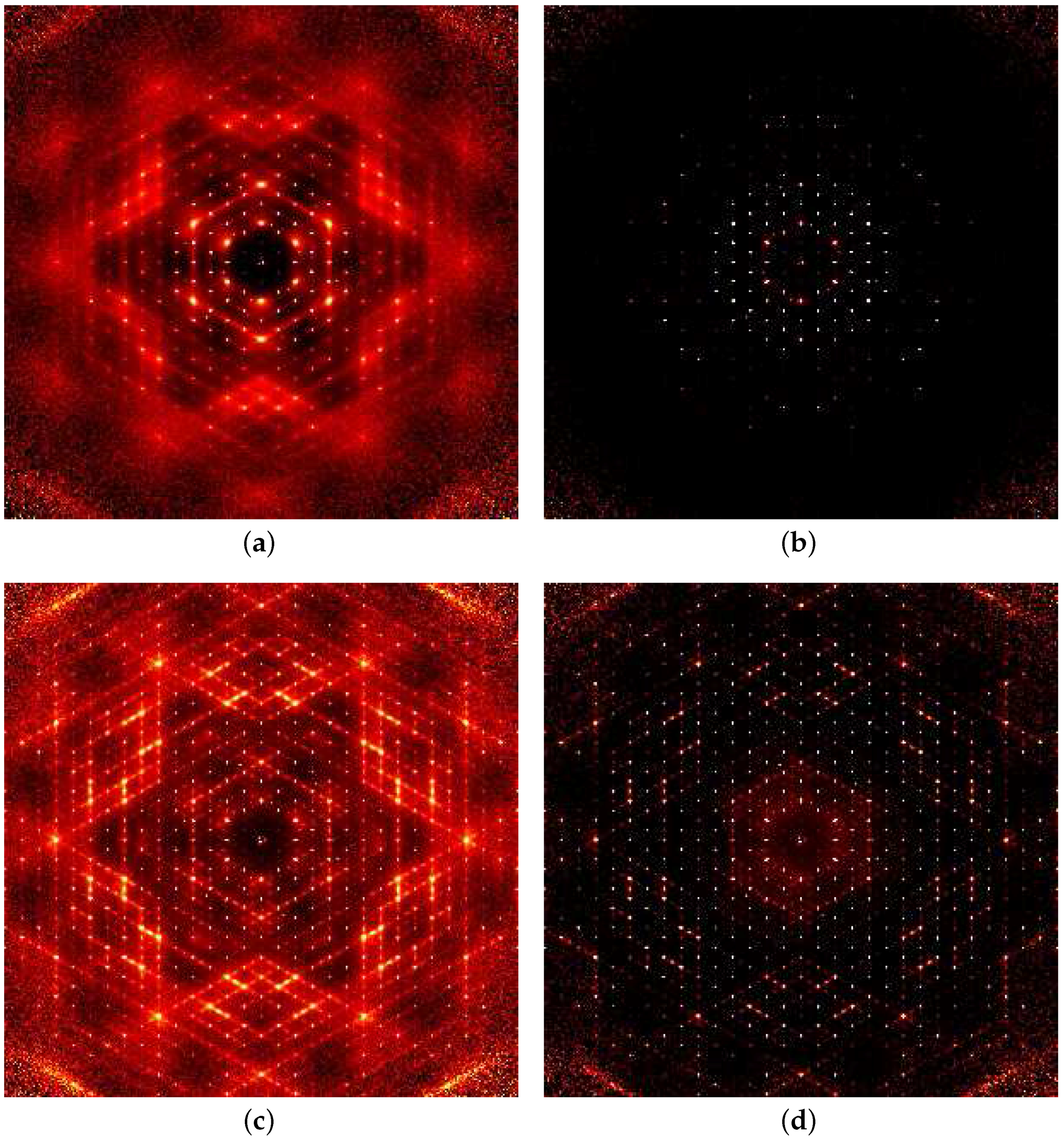
The result of these two modes of data treatment are shown in Figure 4 for the example of benzil. Data recorded at two different temperatures are shown. Figure 4a,b were recorded at 300 K while Figure 4c,d were at 100 K. Panels (a,c) were recorded without cross-correlation applied and thus comprise the energy-integrated intensity (elastic + inelastic) while panels (b,d) are with the cross-correlation applied and show the elastic component only. Since the benzil diffuse scattering is thermal diffuse scattering (TDS) the purely elastic scattering shows only the Bragg peaks. Note that (b,d) are printed on the same intensity scale as (a,c) respectively. The resolution in energy afforded by the cross-correlation analysis is quoted [15] as 8% of the incident energy.
4. Measurement of Diffuse Scattering on a Reactor Source
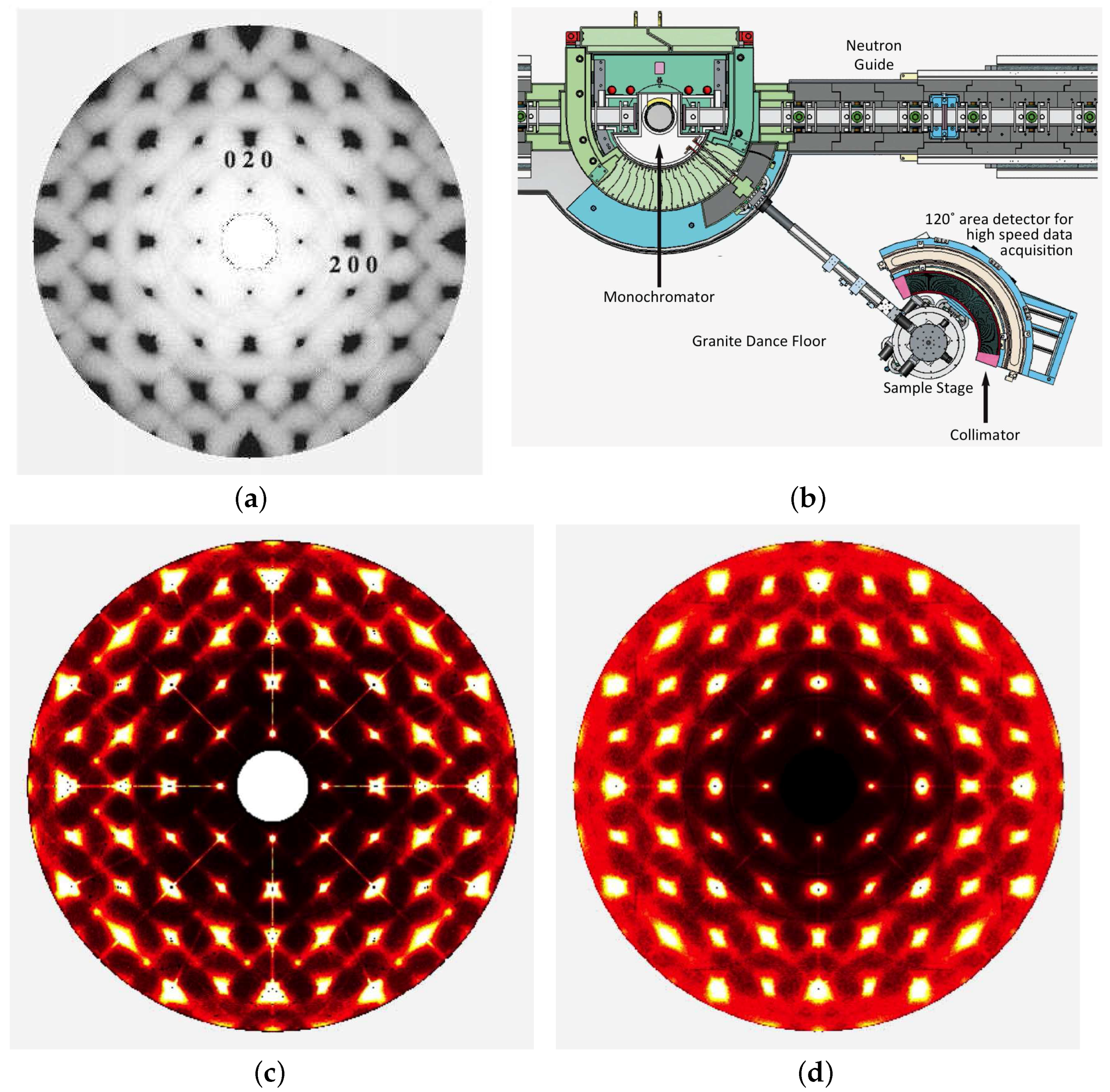
Whitfield et al. [9] have recorded diffuse scattering data for a number of ceramic materials using the Wombat high intensity powder diffractometer at the OPAL nuclear reactor at ANSTO (Australian Nuclear Science and Technology Organisation, Lucas Heights, Australia). Although Wombat (see Figure 5b) was not designed specifically for measuring diffuse scattering data the instrument scientists/designers were well aware of this possible application from the start of the design process. It has attributes that make it quite suitable for recording diffuse scattering, namely a relatively high neutron flux and a large curved area detector. The area detector subtends of in the horizontal plane and comprises 968 pixels in the direction, with each pixel corresponding to deg in . There are 128 pixels in the vertical direction giving some, though not extensive, out-of-plane coverage. Diffuse scattering data are collected by incrementally rotating the sample about a vertical axis, , in steps of . The arrangement is ideal for collecting data in or close to the zero-level section of an aligned sample but by judicious choice of a number of different sample orientations and by using the sample symmetry more extensive coverage of reciprocal space may be achieved.
Figure 5c shows data for the section of lead zinc niobate (PZN) collected at 160 K and Figure 5d shows data collected from the same sample at 500 K. Neutrons of wavelength 1.54 Å were used and this allowed data to be recorded between and 7.5 Å. For each run 600 exposures of 60 s were recorded at intervals, making a total collection time of 10 h. The sample was contained in a cryofurnace but a collimator was used to eliminate scattering from this and only allow neutrons emitted radially from the sample at the centre of the furnace to reach the detector. The data shown in Figure 5c compare well with data shown in Figure 5a that were recorded earlier on SXD (see reference [16]). These SXD data were recorded in 20 h. The sample sizes in the two different experiments were comparable ( versus ). The neutron flux at the sample on Wombat is given as 10 neutrons per s per mm [9]. In both cases the space group symmetry of the crystal was used to average symmetry-related data and obtain optimum signal to noise.
One anomalous feature of the Wombat data are the radial streaks that extend along prominent lattice directions such as , and . The authors attribute these to “incoherent scattering from components in the monochromator and mounting” [9] p. 1425. They appear very similar to features observed on some X-ray patterns recorded using Mo sealed-tube microsources monochromated with doubly reflecting multilayer mirrors [17,18]. In either case, being radially oriented, these streaks cannot be interpreted as disorder or thermal diffuse scattering but must be attributed to a lack of monochromaticity in the incident beam. That these features are less prominent in the high temperature data is perhaps indicative of some increase in mosaic spread of the sample.
The PZN example illustrated in Figure 5 is a good example of the special place that neutron diffraction can have in the study of disorder and local order using diffuse scattering. With X-rays the scattering patterns are dominated by the heavy cations and the effect of the oxygen anions is small while for neutrons the oxygen anions have a much stronger contribution. The patterns in Figure 5 show a number of features displaying strong asymmetry—for example the strong diffuse peaks surrounding a number of Bragg positions such as , , , etc. and the zig-zag arrangement of diffuse lines just above . Corresponding X-ray patterns show much less asymmetry. Such asymmetry is indicative of strong size-effect distortions that must occur on a local scale in the structure.
5. Conclusions
There is no doubt that the last 10–15 years has seen a substantial improvement in our ability to collect neutron diffuse scattering data from single crystals. Though the patterns for benzil obtained on SXD in 2003 [7] stand up well to comparison with the recent data recorded on CORELLI it must be noted that the crystal volume for the latter experiment was only about 1/70 of that of the former experiment. This increase in performance may be attributed partly to the increased power of the SNS source relative to ISIS but also to the moderator, the instrument design and higher efficiency detectors used. From the beginning CORELLI was designed and optimized from the source all the way to the sample [19].
The choice of the benzil example for the CORELLI experiments was useful for making the comparisons with the earlier SXD results. However, because the diffuse scattering from benzil is entirely of thermal origin, it was not an ideal molecular crystal to use for demonstrating the energy discrimination capabilities of CORELLI since the only part of the scattering that is truly elastic is the Bragg peaks. All molecular crystals display substantial amounts of TDS at ambient temperatures but there are many examples in which there is additional occupancy disorder (see for example references [20,21]). CORELLI would allow the study of both the static and dynamic disorder in such materials. It was intended that the CORELLI experiments would be performed alongside experiments on the TOPAZ single crystal diffractometer at SNS [22]. Unfortunately a major mechanical break-down prevented this. TOPAZ is a diffraction instrument similar in concept to SXD with numerous detector banks covering a large solid angle.
The example of PZN described in Section 4 usefully demonstrates that diffuse neutron scattering can be measured on a reactor source if a suitably sized sample is available. This sample size needs to be substantially larger than would be required for CORELLI but comparable to what was used in earlier experiments on SXD. The data obtained for PZN was of comparable quality to data obtained on SXD in 2005. The Wombat instrument at ANSTO is primarily a high intensity powder diffractometer and is not purpose built for diffuse scattering but its use of a large area detector that subtends an angle of in the horizontal plane means that useful diffuse scattering data can be collected. The reciprocal space coverage is by no means complete, however, since out-of-plane coverage is limited. Full 3D data can be obtained using a number of crystal orientations or by making use of the crystal symmetry for high-symmetry specimens.
Acknowledgments
We would like to thank Matthias Gutmann at ISIS for hosting and helping to carrying out the experiments on SXD at ISIS, Christina Hofmann for proposing and hosting the experiments carried out at SNS and Feng Ye and Yaohua Liu for help with carrying out the Corelli experiment. We are also grateful for useful discussions we have had with Stephan Rosenkranz and Darren Goossens. A portion of this research used resources at the Spallation Neutron Source, a DOE Office of Science User Facility operated by the Oak Ridge National Laboratory.
Conflicts of Interest
The authors declare no conflicts of interest.
References
- Keen, D.A. Perovskites take the lead in local structure analysis. IUCrJ 2016, 3, 8–9. [Google Scholar] [CrossRef] [PubMed]
- Welberry, T.R.; Butler, B.D. Diffuse X-ray Scattering from Disordered Crystals. Chem. Rev. 1995, 95, 2369–2403. [Google Scholar] [CrossRef]
- Welberry, T.R.; Weber, T. One hundred years of diffuse scattering. Crystallogr. Rev. 2016, 22, 2–78. [Google Scholar] [CrossRef]
- Keen, D.A.; Gutmann, M.J.; Wilson, C.C. SXD—The single-crystal diffractometer at the ISIS spallation neutron source. J. Appl. Crystallogr. 2006, 39, 714–722. [Google Scholar] [CrossRef]
- Almer, J.; Shastri, S.; Kenesei, P.; Okasinski, J.; Park, J.-S. Beamline 1-ID-B,C,E: High-Energy X-ray Scattering. 2017. Available online: https://www1.aps.anl.gov/Beamlines/Directory/Details?beamline_id=2 (accessed on 30 November 2017).
- Wilson, C.C. Single Crystal Neutron Diffraction From Molecular Materials; World Scientific Publishing Co. Pte. Ltd.: Singapore, 2000. [Google Scholar]
- Welberry, T.R.; Goossens, D.J.; David, W.I.F.; Gutmann, M.J.; Bull, M.J.; Heerdegen, A.P. Diffuse neutron scattering in benzil, C14D10O2, using the time-of-flight Laue technique. J. Appl. Crystallogr. 2003, 36, 1440–1447. [Google Scholar] [CrossRef]
- Rosenkranz, S.; Osborn, R. Corelli: Efficient single crystal diffraction with elastic discrimination. Pramana 2008, 71, 705–711. [Google Scholar] [CrossRef]
- Whitfield, R.E.; Goossens, D.J.; Studer, A.J.; Forrester, J.S. Measuring Single-Crystal Diffuse Neutron Scattering on the Wombat High-Intensity Powder Diffractometer. Metall. Mater. Trans. A 2012, 43, 1423–1428. [Google Scholar] [CrossRef]
- Copley, J.R.D.; Udovic, T.J. Neutron Time-of-Flight Spectroscopy. J. Res. Natl. Inst. Stand. Technol. 1993, 98, 71–87. [Google Scholar] [CrossRef] [PubMed]
- Davis, J.R.; Cywinski, R.; Moze, O.; Hicks, T.J. Cross Correlation Techniques Used in Neutron Polarisation Analysis Studies of Static and Dynamic Phenomena in Disordered Solids. J. Phys. Colloq. 1982, 43, 65–70. [Google Scholar] [CrossRef]
- Rosenkranz, S.; Osborn, R. Scientific Review: Prospects and Challenges in Single Crystal Diffuse Scattering. Neutron News 2004, 15, 21–24. [Google Scholar] [CrossRef]
- Mezei, F.; Caccamo, M.T.; Migliardo, F.; Magazu, S. Enhanced Performance Neutron Scattering Spectroscopy by Use of Correlation Techniques. 2016. Available online: https://www.researchgate.net/publication/308026438 (accessed on 25 August 2017).
- Rosenkranz, S.; Osborn, R. Corelli—Diffuse Neutron Scattering with Elastic Discrimination. In An Instrument Proposal for the Spallation Neutron Source; Materials Science Division, Argonne National Laboratory: Lemont, IL, USA, 2006; pp. 1–31. [Google Scholar]
- Elastic Diffuse Scattering Spectrometer | Neutron Science at ORNL. Available online: https://neutrons.ornl.gov/corelli (accessed on 30 November 2017).
- Welberry, T.R.; Gutmann, M.J.; Woo, H.; Goossens, D.J.; Xu, G.; Stock, C.; Chen, W.; Ye, Z.G. Single-crystal neutron diffuse scattering and Monte Carlo study of the relaxor ferroelectric Pb(Zn1/3Nb2/3)O3 (PZN). J. Appl. Crystallogr. 2005, 38, 639–647. [Google Scholar] [CrossRef]
- Krause, L.; Herbst-Irmer, R.; Stalke, D. An empirical correction for the influence of low-energy contamination. J. Appl. Crystallogr. 2015, 48, 1907–1913. [Google Scholar] [CrossRef]
- Macchi, P.; Bürgi, H.B.; Chimpri, A.S.; Hauser, J.; Gál, Z. Low-energy contamination of Mo microsource X-ray radiation: Analysis and solution of the problem. J. Appl. Crystallogr. 2011, 44, 763–771. [Google Scholar] [CrossRef]
- Rosenkranz, S.; (Argonne National Laboratory, Argonne, IL, USA); Welberry, R.; (Australian National University, Canberra, Australia). Personal communication, 2017.
- Welberry, T.R. Diffuse X-ray scattering and disorder in p-methyl-N-(p-chlorobenzylidene)aniline, C14H12ClN (ClMe): Analysis via automatic refinement of a Monte Carlo model. Acta Crystallogr. Sect. A 2000, 56, 348–358. [Google Scholar] [CrossRef]
- Thomas, L.H.; Welberry, T.R.; Goossens, D.J.; Heerdegen, A.P.; Gutmann, M.J.; Teat, S.J.; Lee, P.; Wilson, C.C.; Cole, J.M. Disorder in pentachloronitrobenzene, C6Cl5NO2: A diffuse scattering study. Acta Crystallogr. 2007, B63, 663–673. [Google Scholar] [CrossRef] [PubMed]
- Single-Crystal Diffractometer | Neutron Science at ORNL. Available online: https://neutrons.ornl.gov/topaz (accessed on 30 November 2017).
Figure 1.
(a) A 2D representation of spallation neutron scattering geometry as implemented on the SXD instrument at the ISIS facility (Didcot, UK); (b) A plan view of the arrangement of detector banks on SXD; (c) A typical TOF spectrum for a single detector pixel. The TOF is given in microseconds (s). Each pixel is 3 3 mm at a distance of m from the sample.

Figure 2.
Diffuse scattering in the section of benzil at 150 K recorded on the SXD instrument at ISIS. (a) Using 1 crystal orientation and a single detector bank (No. 1); (b) Using onecrystal orientation and all six equatorial detector banks (Nos. ); (c) Using three different crystal orientations with a single detector bank (No. 1); (d) Using three crystal orientations and four detector banks (Nos. ) and with m symmetry applied. All neutrons with energies less than ∼27 meV have been excluded; (e,f) highlight the data at lower values of Q; (e) Using detector bank 1 withthree different crystal orientations; (f) Using detector bank 3 with three different crystal orientations.
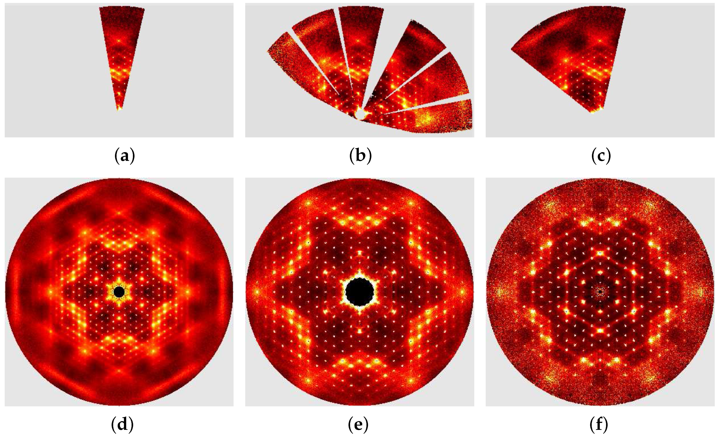
Figure 3.
(a) Schematic diagram showing the operation of the statistical chopper and (b) the use of cross correlation; (b) is reproduced with kind permission of ANSTO (Australian Nuclear Science and Technology Organisation, Lucas Heights, Australia).
Figure 3.
(a) Schematic diagram showing the operation of the statistical chopper and (b) the use of cross correlation; (b) is reproduced with kind permission of ANSTO (Australian Nuclear Science and Technology Organisation, Lucas Heights, Australia).
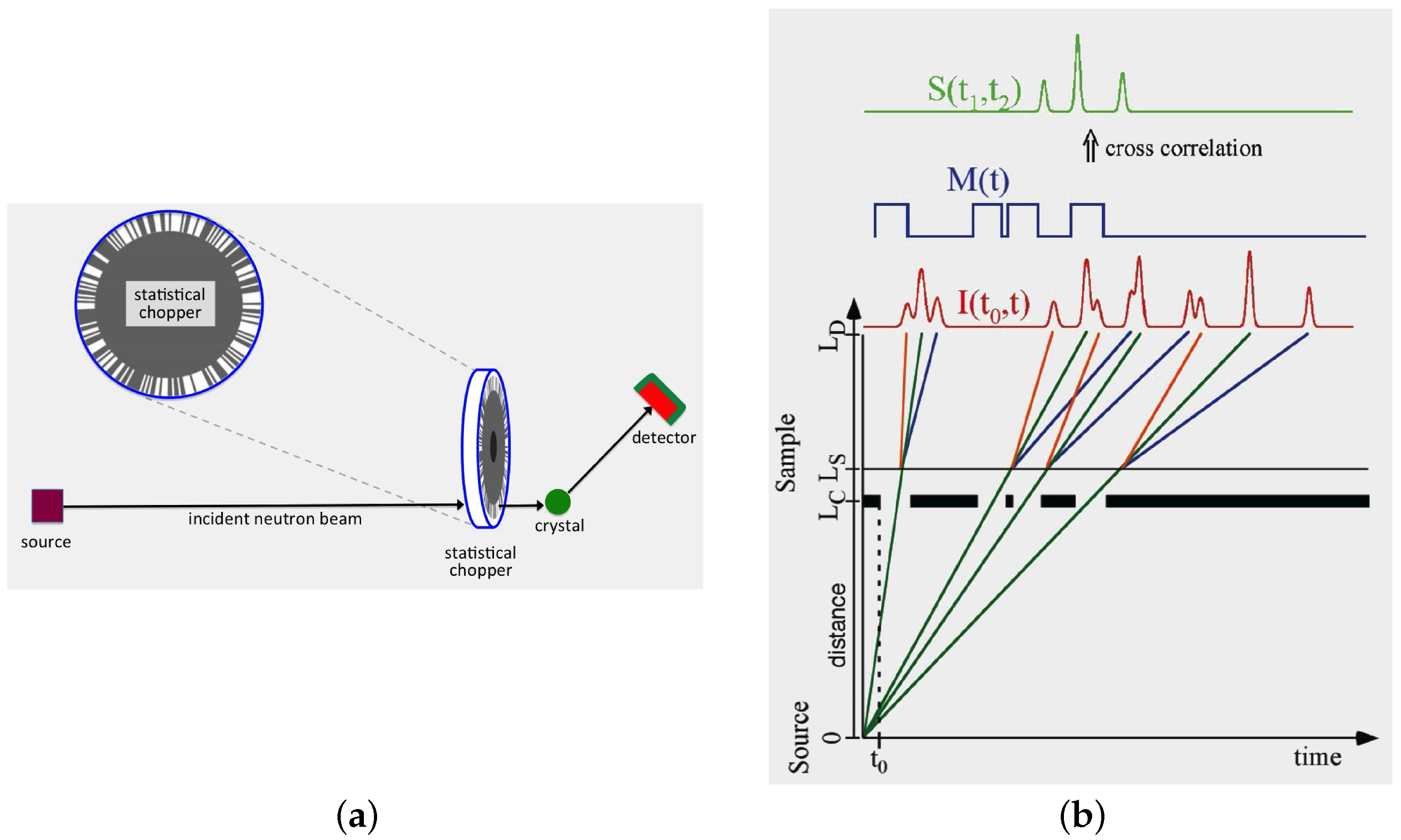
Figure 4.
Diffuse scattering in the section of benzil at two different temperatures measured on the CORELLI instrument at the spallation neutron source (SNS) at Oak Ridge National Laboratory, (Oak Ridge, TN, USA). (a) Total scattering (elastic plus inelastic) recorded at 300 K; (b) Elastic scattering only at 300 K; (c) Total scattering (elastic plus inelastic) recorded at 100 K; (d) Elastic scattering only at 100 K; (b,d) are printed on the same intensity scale as (a,c) respectively.

Figure 5.
(a) layer of lead zinc niobate (PZN) at 150 K measured on SXD (Reproduced from [16] with permission); (b) The Wombat high intensity powder diffractometer at the Open Pool Australian Lightwater reactor (OPAL) nuclear reactor at the Australian Nuclear Science and Technology Organisation (ANSTO, Lucas Heights, Australia) used to collect single crystal diffuse scattering data from PZN; (c) layer of PZN at 160 K measured on Wombat; (d) layer of PZN at 500 K measured on Wombat. In both (c,d) artifacts due to high Bragg peak intensities have been removed and symmetry averaging has been applied; (c,d) are reproduced from [9] with permission.

© 2018 by the authors. Licensee MDPI, Basel, Switzerland. This article is an open access article distributed under the terms and conditions of the Creative Commons Attribution (CC BY) license (http://creativecommons.org/licenses/by/4.0/).
Share and Cite
MDPI and ACS Style
Welberry, R.; Whitfield, R. Single Crystal Diffuse Neutron Scattering. Quantum Beam Sci. 2018, 2, 2. https://doi.org/10.3390/qubs2010002
AMA Style
Welberry R, Whitfield R. Single Crystal Diffuse Neutron Scattering. Quantum Beam Science. 2018; 2(1):2. https://doi.org/10.3390/qubs2010002
Chicago/Turabian StyleWelberry, Richard, and Ross Whitfield. 2018. "Single Crystal Diffuse Neutron Scattering" Quantum Beam Science 2, no. 1: 2. https://doi.org/10.3390/qubs2010002