Article

LiBAT: A High-Performance AC Battery System for Transport Applications

1
TWT GmbH Science & Innovation, Ernsthaldenstraße 17, 70565 Stuttgart, Germany
2
School of Engineering, Liverpool John Moores University, Byrom St, Liverpool L3 3AF, UK
3
LION Smart GmbH, Daimlerstr. 15, 85748 Garching, Germany
4
Dassault Aviation, 78 Quai Marcel Dassault, CEDEX 300, 92552 Saint-Cloud, France
5
School of Science and Technology, City, University of London, Northampton Square, Clerkenwell, London EC1V 0HB, UK
*
Author to whom correspondence should be addressed.
Designs 2023, 7(3), 74; https://doi.org/10.3390/designs7030074
Submission received: 19 March 2023 / Revised: 12 May 2023 / Accepted: 17 May 2023 / Published: 12 June 2023
(This article belongs to the Special Issue Battery System Design)

Abstract

:
The paper proposes a novel battery design for high-performance transport applications that is immersion-cooled and switched by a multi-level inverter. Advantages of the proposed AC battery design in terms of weight, modularity, scalability, performance, reliability and safety are presented. To demonstrate the applicability of the design, an electrically powered glider use case is addressed. The derived battery system is evaluated by means of theoretical analysis, simulation and prototyping. Simulations showed that the used multi-level inverter (MLI) power electronics modules could successfully run the motor without additional power electronics and charge batteries from a 110 V AC source. The prototype implementation with a motor-driven propeller demonstrated power levels of up to 3.3 kW, with a behavior in accordance with simulations. Guidelines to further advance the technology readiness level including control strategies and hardware design were derived to overcome limitations in the prototype realization that could not be addressed within the project budget. Finally, research topics to evaluate additional performance metrics such as efficiency and aging behavior are suggested.

1. Introduction

Reduction in emissions from the transport sector is key to meeting the goals of the Paris Agreement [1], with improvements to battery performance being a key enabler [2]. Work Package 3 of Flight-Path 2050 [3] discusses disruptive trends in the transport manufacturing industry covering future demands for a variety of transport sectors. Two energy storage candidates to replace fossil fuels in transport are lithium-based batteries and hydrogen (being used within combustion cycles or fuel cells). Depending on the vehicle type and distance range of the transport application, all the mentioned strategies show promise [4,5,6,7]. For fuel-cell systems, a buffer battery is required to comply with the highly dynamic demands present in transport applications. Thus, Li-ion storage systems play a decisive role in the technical feasibility of greener transport applications.
Electrified road mobility became achievable around the beginning of the new millennium when battery technologies such as NiMH had advanced sufficiently and became affordable for hybrid electric vehicles such as the Toyota Prius [8]. More recently, the increased demand for small and light batteries due to a booming mobile device market led to the rapid development and improvement of a variety of lithium-based (Li) battery technologies [9]. Further pushed by zero-carbon initiatives, they have become the preferred solution in several guises such as Li-NMC, LiFePO4 and Li2TiO3 with each category having a variety of design features to improve performance [10]. At present, Li-ion batteries seem to be the most viable approach for the realization of transport applications with further potential from promising upcoming technologies such as Li-sulfur, Li-metal and Li all solid-state [11].
Despite advances in Li-ion cell technology over the past years, current technologies produce batteries that are relatively heavy for many vehicle applications. A reduction in overall battery system mass is crucial for vehicles, particularly aircraft [12], and for longer-range automotive use. There is much research concerning improvements in gravimetric and volumetric energy densities at cell and electrode levels [11,12,13,14]. However, higher energy densities also pose safety risks and demand challenging thermal management requirements. Innovative and future cell chemistries mentioned before aim to tackle both energy density and safety issues. Current Li-ion technologies still rely on additional ancillaries assuring safe operation. Thus, system-level energy and power densities are a more practical key performance indicator than cell-level values. In this context, efficient system integration and battery design play a key role. Over the past years, considerable advances have been achieved by engineering design approaches in parallel to the mentioned cell-chemistry improvements [11]. Still, further integration potential exists, and both the design of battery systems and vehicle integration are a focus of today’s research. System integration comprises mainly the geometrical, electrical and thermal integration of both cells and packs with corresponding ancillaries. For transport applications, three groups of key ancillaries can be named: power electronics, thermal management system and battery management system (BMS).
Modern efficient electric motors require power electronics to generate AC waveforms from DC batteries. A variety of electrical pack designs and power-converting functions exist, with the two-level converter with pulse-width modulation being the most prevalent solution in the current market. Transformerless multi-level inverters (MLIs) follow a more distributed strategy, by synthesizing a desired voltage waveform from several levels of DC voltages. They are commonly realized by full H-bridges, to bypass or to switch each DC level with both positive or negative polarity. Around 1999, Tolbert et al. [15] described how segmenting the batteries or DC source and using the aforementioned multi-level approach leads to efficiency gains and the ability to operate above the individual semiconductor voltage limits. This MLI concept can be considered an “AC battery” that can be configured in software for a variety of applications beyond transportation. Implementation in an application-specific integrated circuit (ASIC) can be up to 10 times lighter and safer than alternatives at the same or lower cost [16] with maximum voltage unconstrained by the voltage limits of the semiconductors. Several modules can be connected in series to generate voltages of up to 11 kV and higher. Until recently, the high cost and performance limits of transistors have hindered the incorporation of MLI technology in broader markets. The main losses in an MLI system are conduction losses in the switching elements. Modern MOSFETs now have very low on-resistance and, hence, low conduction losses. Competition between manufacturers is driving this parameter down all the time, meaning that conduction losses are likely to improve over time, promising similar or better performance than SiC transistors but at significantly lower costs. Furthermore, active battery management and charging capability can also be included [17,18], posing further motivation from a system perspective. In 2019, Riley et al. discussed the viability of these techniques considering recent advances in MOSFET performance and cost being applicable to many areas of electric vehicles on land and sea and in the air [16] with associated benefits discussed in [19]. Conventionally, for DC/AC converter architectures, power electronics (PE) converters are typically housed as a self-contained application being usually cooled independently, increasing system complexity and adding mass.
In the target high-performance applications, Li-ion cells dissipate a considerable amount of heat, especially at a low state of charge (SoC) or high C-rates, and thermal battery management directly influences the performance and life span of the battery. Cell performance and aging mechanisms are strongly dependent on temperature, and optimal operation occurs within a narrow temperature band. Similarly, temperature stratification at both cell and pack levels leads to inhomogeneous cycling and electrical imbalance reducing both the power performance and energy release capability of the battery. Safety requirements necessitate active cell cooling to prevent thermal runaway. Kim et al. evaluate the thermal management requirement of Li-ion batteries in real-world applications where wide ambient temperature ranges are required [20]. Chen et al. [21] and Wang et al. [22] discuss various cooling techniques to increase safety, extend pack service life and reduce cost. In many applications, indirect liquid cooling is used, for example, in all the Tesla car models and in the BMW i3 [22] offering a good trade-off between efficiency, complexity and costs. Sundin et al. and Dubey et al. describe innovative single-phase liquid immersion cooling (direct liquid cooling) to deliver high energy dissipation rates and achieve exceptional safety margins in the mitigation of thermal runaway [23,24]. The immersion approach is especially suitable for high-power applications requiring also high levels of safety such as aircraft, high-performance vehicles and marine craft.
This paper presents the design of a modular Li-ion battery system with a very high level of integration bringing the two approaches mentioned above together: MLI and immersion cooling. The design was developed within the HORIZON 2020 project LiBAT [25,26] coordinated by TWT GmbH and is suitable for a wide variety of applications especially where C rates above 2 are needed (see some examples in Table 1).
The paper is organized as follows: Section 2 provides further insights into the advantages of the MLI and immersion cooling technology and introduces their integration into the modular LiBAT design. As a proof of concept, Section 3 describes the adoption of the proposed design to a fully battery-powered small lightweight aircraft, more precisely a glider. Section 4 provides insights into the simulation and prototyping methods pursued for system validation. Depending on the use case, both simulation and measurements on the prototype were performed to demonstrate the performance of the system. The results of the use case performance are presented in Section 5. Finally, Section 6 concludes the paper with a discussion of the achieved performance and provides advice for further research to advance the technology readiness level (TRL) of the presented LiBAT technology.

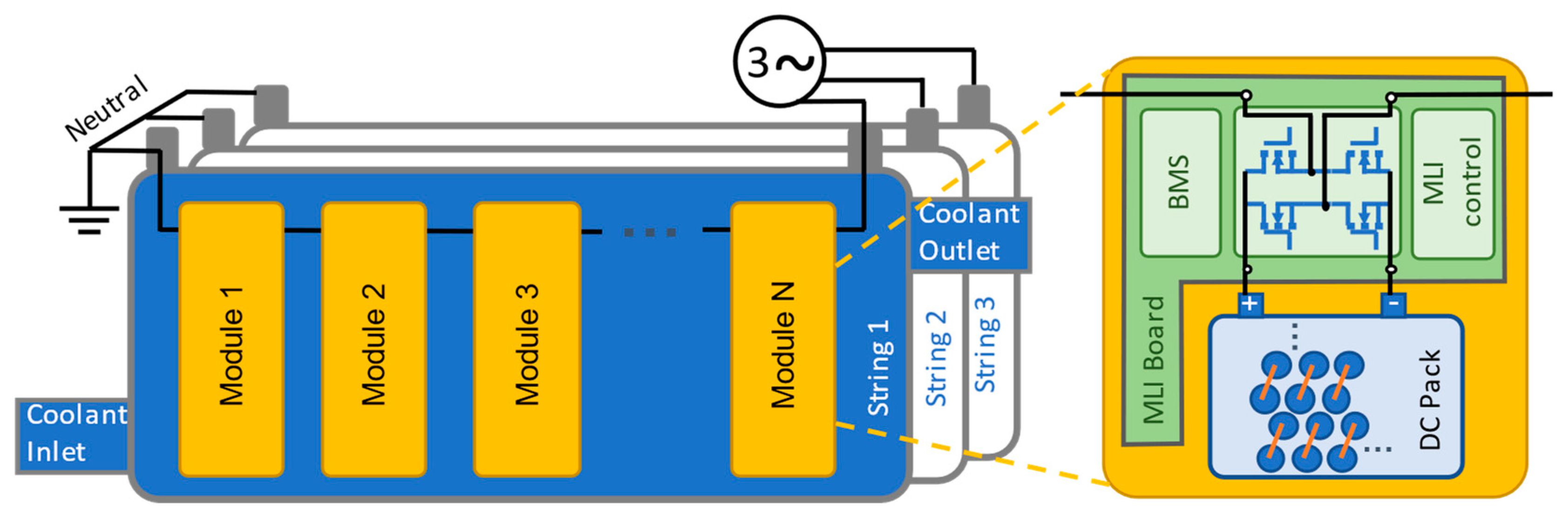
2. Modular AC-Battery Concept and Design Principles

The proposed battery design targets a reduction in hardware mass and gains in performance through a high degree of integration with respect to thermal management and power-converting functions. For this purpose, the MLI and immersion cooling technologies previously introduced are combined.
Figure 1 shows the modular battery design consisting of three identical strings segmented into low-voltage modules connected in series by power electronics boards. Each module comprises a DC battery pack that can be dynamically switched on (both with positive or negative polarity) or bypassed by a full H-bridge circuit (see Figure 1 (right)). Thus, the technology being used has a cascaded H-bridge (CHB) topology. In the context of MLI technology, each string can provide AC waveforms through active H-bridge driving, as sketched in Figure 2. The quality of the target waveform increases with the number of used DC levels and the application of pulse wave modulation.
This architecture enables the operation of the proposed AC battery in three modes: motor control, powering auxiliary devices and charging (from the electrical bus system). Additional dedicated hardware for the named operation modes is unnecessary. The number of modules arranged in series, as well as the dimensioning of the DC packs, can be varied according to the targeted application. BMS, power electronics and driving modules are integrated into a so-called MLI board (see Figure 1).
In each of the three mentioned operation modes, the MLI technology not only adopts power conversion functions but can also directly perform DC pack balancing (i.e., battery module balancing). This is done by choosing a favorable sequencing of relevant modules (see Figure 2). Similarly, the failure of single modules can be compensated by software measures.
The highly integrated MLI modules, containing MOSFETs, dissipate high heat flux densities locally, and the application of immersion cooling extends their operation range considerably. Still, compared to the cumulative dissipation power of the cells, overall PE losses are small. The immersion approach can thus handle the thermal management of PE in the same coolant cycle of the cells increasing the level of integration. Dielectric immersion cooling of both the battery pack and power electronics enables high power capabilities and tight geometrical integration.
A variety of fluids were investigated, and NovecTM was chosen due to the following advantages: It has a very high thermal reserve (specific heat capacity), so in the case of thermal runaway events, it offers additional protection as evaporation sets in to absorb large additional amounts of energy to delay thermal propagation to other cells. The boiling point can be engineered through additives to perfectly match application requirements. Being highly dielectric, it allows direct immersion cooling of cells and power electronics making the use of a single coolant cycle feasible. Its flow properties, e.g., viscosity, demand low pumping power. Combined with its high heat capacity, very small channels and low flow rates can be used due to its compact design and high cooling efficiency.
The proposed modular AC-battery design has the following main advantages:
  • A reduction in system components leading to indirect mass and space savings.
  • Modularity and scalability. The LiBAT technology is applicable to a wide range of system voltages and capacities.
  • Performance increase. MLI has higher efficiencies due to the lower switching losses. Furthermore, direct immersion cooling boosts the operation power range of the MLI.
  • Reliability. The battery system can compensate for the failure of single cells or inhomogeneities.
  • Safety. When not in operation, only low voltage is present in the system. Furthermore, the powerful cooling system makes operation at high power feasible and prevents overheating and thermal runaway propagation.
One application of these design concepts is shown in detail in the following section.

3. Glider Application for Demonstration

The installation of electric propulsion systems on gliders to achieve both self-launch and flight-sustaining capabilities was progressively realized. Among the advantages are lower noise and vibration levels, lower operational and maintenance costs and higher reliability [31] over combustion engines. This application profits considerably from the weight-saving potential of the here-proposed design approach and takes advantage of the motoring and charging operation modes mentioned in Section 2. Within the motoring use case, autonomous take-off requires a few minutes of peak-power operation, whereas sustaining level flight requires efficient continuous power operation. Due to the variability in landing place infrastructure, the charging use case should not rely on sophisticated ground equipment.

3.1. Application Targets and Requirements

To evaluate the performance of the here-proposed design, this study aligns with the requirements of the CleanSky project [26] with the take-off and climb power estimated from the regulations in [32] and published in [33]. These requirements can be summarized as follows:
  • The electrical energy system (EES) shall be divided into an even number of battery units, forming two sets of equal mass, one for each wing. The dimensions of one battery unit shall not exceed 110 × 200 × 1500 mm.
  • The mass of the EES shall not exceed 55 kg (including the interconnections, housing, battery cells, connectors, protection devices and integrated electronics).
  • The EES shall have an energy density >200 Wh/kg available at 1 C discharge.
  • The EES shall include a high-power battery charger from 115 V AC/400 Hz airport ground power carts or three-phase 240 V–380 V AC/50 Hz euro grid power able to reach a charging power capability ≥60 W/kg.
  • The EES shall have the capability to connect the pack directly and simultaneously to two suitable three-phase electric motors providing peak power of >500 W/kg for at least 2 min, and continuous minimum power of 20 kW shall be provided by the EES to the motors.

3.2. LiBAT Detailed Architecture for the Glider Application

Based on the modular design presented in Section 2, a TRL4 prototype for the glider application was developed as a proof of concept. The design of the EES comprises two units each containing three identical strings. For demonstration, in this study, only one unit is considered, and its functional diagram is depicted in Figure 3. In the figure, the system architecture including corresponding ancillaries and interfaces (thermal, electrical and communication) is sketched. Each string sums up five MLI modules each consisting of a supercell (DC battery), an MLI board and a measurement board for the BMS. The MLI board incorporates mainly safety fuses, the full H-bridge circuit and a corresponding control unit.
The thermal management cycle is also sketched, where all three strings are connected in parallel. Heat generated by the battery cells and power electronics is removed by the heat exchanger or chiller. In cases where ambient temperature conditions are below cell limits, an electric heater can be used to heat up the system. A pump induces the appropriate flow rate. An expansion tank ensures that trapped air can escape from the system and acts also as a filler neck for the Novec™ coolant manufactured by 3M. As will be explained in Section 4.2, an interface board and emulation equipment are employed to distribute sensing and control signals. Finally, an external box is used to switch between the motor and power source (depending on if the motoring or charging operation is to be tested).

EES Dimensioning and Geometrical Design

The target system energy density of 200 Wh/kg is particularly challenging considering that Li-ion cells currently available in the market provide cell densities ranging between 200 and 300 Wh/kg. The situation concerning power density is also challenging in combination with the required capacity. Thus, the whole weight margin of 55 kg for the EES (or 27.5 kg per battery unit) is exploited when dimensioning. Upon this assumption, the requirements for the three main glider use cases can be specified as listed in Table 2.
For the cells, NCA/Graphit + SiO chemistry was chosen because of its high power, acceptable energy density and availability from several suppliers such as Sanyo, Panasonic and Murata, with the Murata VTC6 chosen for the demonstrator. The 18,650-cell format provides both good thermal performance and packaging volumetric efficiency. The chosen cell has a nominal capacity of 3120 mAh and a nominal voltage of 3.6 V. Further properties and operating limits are listed in Table A1. To meet reliability requirements, components are de-rated according to reference [33]. A figure of less than 75% for all electrical components was used. At the maximum cell voltage of 4.2 V and the drive absolute maximum requirement of 80 V, the passive components have a 100 V rating. This results in each module having 12 cells in series with 2 cells in parallel needed as derived from the energy calculations (12s2p). The advantage of these individual supercells is that the voltage of each module remains below the high-voltage limit allowing the use of lower-cost MOSFETs and drivers with typically an 80 V rating. In the present implementation, an NVMFS6H801N MOSFET manufactured by Onsemi (Phoenix, AZ, USA) was used. With the minimum cell voltage of 2.4 V, 12 cells per module (to accommodate de-rating conditions) and a peak system voltage of 115 2 , five modules are required, and the target capacity and power require 2p to control the three-phase 115 V motor. To smooth voltage waveform, the MLI control board uses PWM with higher (20 kHz) switching speeds to simplify filtering components, required for EMI suppression and system stability. The chosen fast prototype platform “RT box 1” (see Section 4.2) limited the switching frequency to the mentioned 20 kHz. In a final implementation using a dedicated hardware controller, higher switching frequencies are easily feasible.
Figure 4 shows the geometrical design of one of the three identical strings in the unit. Cylindrical cells are densely packed inside a common housing flooded by the coolant. Small channels are left between cell surfaces. Cell connectors in the housing group corresponding cells into the mentioned 12s2p modules. The MLI boards are placed outside the housing, being indirectly cooled by a solid aluminum plate. This decision was made in favor of prototyping accessibility. In the future, the whole MLI board can be miniaturized as an ASIC and also placed inside the housing. Flooded with the coolant, the operation margin of PE components would be considerably extended.

4. Methods for System Verification and Validation

For the proof of concept, system validation was performed by a combination of theoretical analysis, simulation and prototype demonstration for the given glider use case requirements.

4.1. Simulation (Verification)

The simulation approach is based on a multi-scale ansatz on sub-functions grouped by means of time scale (see Table 3). For each considered time scale, different simulation approaches are used to deal with numerical challenges.
In the following, the derivation of key component models in Modelica for the system simulation is explained.
H-bridge in MLI boards: The chosen PCB components using the Tina™ simulation were simplified into Modelica with four idealized MOSFETs, ideal diodes and a 60 μF bypass capacitor in each module with conductive losses accounted for from the average on-resistance (Ron) from Tina, switching losses being neglected initially then estimated during post-processing.
Cells: The EEC comprises a voltage source term modeling the open circuit voltage (OCV) of the battery electrodes, a serial resistance Rs modeling the ohmic losses (electrolyte, active materials and current collectors) and two RC-parallel circuit elements modeling voltage transient effects, in particular charge transfer. Electric cell losses were modeled using a lumped thermal capacity model with a single thermal mass.
Supercells: Modeling assumed equal behavior of all 24 cells with the supercell current and voltage scaled according to the number of cells in series and parallel, with resistors simulating interconnections and joints.
Controllers: For each use case, an overall system voltage controller determines the target voltage waveform for the MLI and drives all H-bridges with corresponding PWM signals to induce the target voltage waveform. The control is performed in a synchronous dq reference frame after transforming the measured currents through Clarke and Park transformation. Standard proportional integral (PI) controllers were used to regulate the dq quantities. Controlled voltages are then transformed back into the three-phase abc frame and provided as a reference signal for the MLI controller.
Motor: A Modelica Standard Library generic electric motor model based on the fundamental wave theory, assuming a simplified magnetic field in the gap between the rotor and the stator and accounting only for its fundamental spatial wave, was used. Phase windings were assumed to be symmetrical, considering friction losses, stray load losses, permanent magnet losses, heat losses in the temperature-dependent stator winding resistances, heat losses in the temperature-dependent damper cage resistances and core losses (only eddy current losses, no hysteresis losses).
Propeller: Modeled as a quadratic-speed-dependent torque, which, at its nominal speed, reaches the desired torque.
Thermal management: A quasi-stationary approach with iterative coupling between the electrical and thermal domains is followed. The domains are coupled by means of the electrical loss power and average cell-stack temperature. Thus, a homogeneous distribution of both electrical and thermal states is assumed throughout the pack. This assumption was reviewed by the two-dimensional fluid-dynamic simulation of NovecTM coolant flow through the pack as depicted in Figure 4. The well-spread and homogeneous flow field leads to very small temperature gradients in the domain.
Figure 5 schematically shows the integration of the mentioned components to model the proposed battery in the relevant use cases. The model of the battery unit consists of three identical strings connected in a star configuration to either the ideal charger (Figure 5, left) or a three-phase motor and corresponding load (Figure 5, right). An inductive element is placed between the battery unit and the appliance for filtering purposes. For simplicity, cable impedances between the mentioned components are neglected. Voltage and current sensors at the corresponding positions shown in the figure feed the system controller, which delivers the PWM-modulated MLI switching signals for all modules. In the motoring use case, a simplified speed controller is employed.

4.2. Prototyping (Validation)

The proof-of-concept prototype focused on one battery unit as introduced in Section 2 The battery housing and structural components of the corresponding strings were 3D-printed from polyamide PA66 reducing the number of single parts, simplifying assembly, reducing cost and coolant sealing efforts and favoring overall housing mass.
As already sketched in the architecture diagram, Figure 3, an interface board is used to connect driving and sensing interfaces with the real-time central controlling unit. For this purpose, a Plexim™ RT-Box 1 [37] real-time controller was used, which was directly programmed from the PLECS software version 4.4 [37], in which all control and management algorithms are written. For the motoring use cases, speed demand was directly inserted by the user. The motor is driven by a three-phase voltage calculated from the power demand input and present motor speed, then input to the MLI controller. In the charging case, a similar method for connecting a generator or inverter to the grid must be used [38]. The RT box (MLI controller) matches the voltages of the three strings to the mains in terms of both voltage and phase via the mains’ sync box, then closes the relays and connects the MLIs to the mains (see Figure 3). The controller then adjusts the voltage of the MLIs so that the current that flows from the mains to the strings is regulated. A shuffling sequence similar to the one in the motor mode of operation then ensures that each battery is charged to the required level.
The BMS estimates the key states (state of charge (SoC), and state of health (SoH)) of all cells and ensures safe operation according to the manufacturer’s specification. It comprises bespoke LION Smart LCM (control module) and LMM (measurement module) units [39]. Key signals gathered by the LCM board are also provided to the control algorithms via an interface board.
Similarly, an external box encompasses all electrical safety devices (e.g., fuses and relays) and the corresponding interfaces to the appliances (electric motor or three-phase source for charging). Inductors are required to filter out the PWM switching frequency to comply with the mains’ EMC criteria. Analog monitoring equipment (voltage and current measurements) is also attached to this external box.
A laboratory test rig shown in Figure 6 integrates the prototype with the motor and propeller. The three-phase AC-battery unit controlled a RET 60/3 BLDC outrunner motor from ROTEX Electric connected in a star configuration and attached to a two-blade aeronautic pusher propeller from E-Props with ground-adjustable pitch. The ROTEX Motor has an operating voltage of 120 Vrms per phase and both star and delta configuration is possible.
In the motor control mode, a field-oriented control (FOC) algorithm is used. The MLI module control, taking the values of the battery state of charge (SoC), switches each H-bridge in sequence to synthetize the required AC voltage waveform and frequency demanded by the motor/charge controller. More details of its operation are given in reference [19].Similarly, in the battery-charging mode, bus and H-bridge voltages are synchronized using software charging algorithms that hold battery manufacturer limits.

5. Results and Discussion

5.1. Simulation Results

5.1.1. Motoring Use Case

Figure 7 shows the simulated voltage and current waveforms of one battery string terminal (blue traces) at a reference operation point (SoC = 90%, T = 298.15 K) and 3.3 kW continuous power, after reaching steady-state speed. Four MLI levels/supercell combinations gave close to 200 V to generate the waveform. The fifth MLI is only needed at higher voltages or at lower SoCs. Due to the small motor and filter inductivities, the phase shift between fundamental terminal voltage and current is small (0.47 rad). The orange traces show the voltage and current of one supercell in the string. Again, MLI level assignment alternates periodically to assure charge balance between all supercells. Voltage polarity switches while current flow remains negative (as discharging) at almost all times although some positive current spikes do arise. It is expected that they can be avoided in future designs by a more elaborated control strategy. Further investigations in this direction were beyond the scope of the presented work.
Simulations also allowed to evaluate the star and delta configurations of both motor and battery strings, highlighting the corresponding advantages. Table 4 summarizes the results, giving corresponding string currents for targeted continuous (10 kW) and peak (13.75 kW) power. The results show that the motoring power requirements are met by the EES (current cell limits shown in Table A1 are not violated) at the reference operating point. The MOSFET design in the demonstrator can be easily improved to support estimated currents. Furthermore, it must be mentioned that in real glider operation, considerably higher rotational speeds are feasible, thus increasing the voltage level of the motor.

5.1.2. Charging Use Case

To illustrate the general system behavior, the voltage and current waveforms of one battery string (blue traces) are shown in Figure 8 at the reference charging operating point (SoC = 50%, T = 298.15 K). While the voltage polarity of the given module alternates, its current flow is always positive and thus charging the batteries. At the given SoC, four H-bridges are used to generate the voltage waveform. The orange traces show the voltage and current of one supercell in the string. In accordance with the implemented control strategy, supercell level alignment alternates after each fundamental period. Minor high-frequency oscillations due to the PWM are present. As can be seen, PWM switching occurs only at reduced voltage levels and thus only at a portion of the sampling period, thus reducing switching losses. Unlike conventional converters where all the voltage is applied across the switching elements, used CHB only has to switch one module of voltage, i.e., 50 V. The resulting cell currents of 3.47 A (2p supercell configuration) at the peak lie well below the cell manufacturer’s stipulated limits. In the shown example, charging power is 1.65 kW, verifying the power requirements set in Section 3 for charging at the reference operation point.
Grid regulations were not considered in detail but left for future work and higher TRLs. Nevertheless, harmonic distortion was investigated briefly because of its possible side effects such as noise generation, motor torque oscillations and disturbance to synchronization techniques. With the rudimentary control strategy realized in the project, the voltage harmonic distortion THD was 8.6%. With an optimized control strategy, expected low voltage grid requirements of around 5% are achievable. Furthermore, the inductor between the battery and the grid can be varied to improve THD. For this project, an inductance of 160 μH was chosen as a good balance between control stability and current waveform quality, on the one hand, and power ratio, mass and cost, on the other.
After analysis at the reference operating point, performance at different SoCs and temperatures [40] was analyzed. The required charging power of P = 1.65 kW was achieved at all investigated SoC levels (T = 298.15 K) while peak and average cell states lay within the stipulated voltage and current limits. As expected, losses at low SoCs are larger, and charging efficiency improves at higher SoCs. MLI losses and ohmic plus switching are estimated to be as low as 0.3 ± 0.03 W per switch throughout the whole SoC range. Furthermore, the behavior at various temperatures was also investigated. The required power of P = 1.65 kW was achieved above T = 0 °C; for lower temperatures (cold-soaked use case), extra heating procedures before charging are necessary.

5.2. Prototyping for Motor Testing

The motor use case was tested on the developed prototype at the reference operating point (room temperature and starting SoC = 90%), while the other use cases and other SoC levels were evaluated by simulation. The motor with an attached propeller was powered successfully by the developed AC battery (i.e., MLI), at a variety of propeller velocities and pitch angles. Figure 9 shows the measured power and electric motor currents. The largest power was achieved when the propeller was set at a 3.9° pitch angle using the simplified motor controller described in Section 4.2. This is because the voltage level of the motor scales with the velocity and thus smaller currents are needed for the same power. In the chosen configuration, the current limits of the installed MLI board fuses turned out to be the bottleneck. Initially, a current of 12 A gave a power of 735 W and a speed of 1705 rpm. The quadrature current was then increased in steps of 4 A up to 30 A (see Figure 9). Finally, for a 30 A quadrature current, a maximal power of 3.25 kW at 2850 rpm was achieved. Due to the speed limit of the propeller of 3000 rpm and the current limit of the MLIs, no further operation points were tested.

5.3. Mass Discussion

For the battery unit prototype, the measured weight including the housing, module, BMS, external connectors, power conditioning and thermal management sums up to 27.6 kg, as detailed in Appendix B. The tested demonstrator comprises an integration factor of 1.46. For judging the LiBAT battery concept, this value is not representative though, since several components were chosen based on prototyping flexibility rather than optimal weight. The demonstrator can thus be easily optimized by trivial means (substitution of heavy components) without modifying the design. Some very feasible and straightforward design changes at higher TRLs (e.g., novel cell chemistries, thermo-management and housing optimization, etc.) pose further weight reduction potential. A brief explanation of the most promising straightforward design changes is given in Appendix B. Assuming the mentioned design optimizations, the overall mass might be reduced to 22.8 kg leading to an integration factor of 1.36 (see also Appendix B).
Looking beyond the actual weight of the battery, the LiBAT battery design integrates two important power electronics functions into the battery, replacing a charger and the power electronics for the motor, with a total mass of typically 1.5 kg = 1.25 kg (motor controller) +0.25 kg (charger). In contrast, the extra battery mass due to the MLI power electronics is only 0.5 kg (0.2 kg after design optimization). On the system level for the glider, this gives a mass advantage of 1.0 kg (1.3 kg with design optimization). Taking this effect into account, the effective integration factor is reduced to 1.28 (including design optimizations), while common systems available in the market for vehicle transport applications reach an average of 1.54 (see [41]).

6. Summary and Conclusions

The paper proposes a novel battery design for high-performance transport applications using a combination of immersion cooling for the thermo-management and MLI technology for power-converting functions. The proposed design is modular and scalable, being applicable to a wide range of scenarios. Use cases with high power and C-rate demand benefit most from the major advantages such as increased safety, reliability through intrinsic cell balancing capabilities and light weight.
As a proof of concept, the proposed design was applied for a glider use case. Simulations of the electrical properties of the compact LiBAT system showed that power for take-off and level flight met the use case requirements, and charging from 115 V AC was exemplarily demonstrated. Experimental results from a laboratory prototype using an appropriate motor and propeller were achieved demonstrating power levels of up to 3.3 kW. Test rig limitations concerning propeller speed limited the power range of the experiments. The current limits of the selected fuses used in the prototype further constrained the achievable power of the experiments. Both limitations can easily be overcome in advanced test rig and prototype realizations. The studied design demonstrated the functionality of the proposed technologies and shows directions for further development. To advance the TRL of the battery design, the integration of MLI boards into productive ASIC boards using more robust MOSFETs in terms of currents and voltages than the model mentioned in Section 3.2 is suggested. The said ASIC can be fully immersed in the dielectric coolant pushing the power capability of the MOSFETs further. Furthermore, advanced control strategies, especially in motoring mode, can further improve the quality of the obtained waveforms (e.g., if different modulation methods are considered or by using the maximum torque per Ampere (MTPA) approach).
The results presented in this paper encourage further general investigations into this design: the performance of the proposed design in terms of efficiency should be quantified and compared to conventional two-level AC/DC converter architectures. Furthermore, the impacts of high-frequency micro cycling on battery aging due to the PWM should be studied and put in contrast to idle phases present within MLI sequencing. Furthermore, control strategies incorporating intrinsic cell balancing should be studied, and their contribution to reliability (fault tolerance and compensation of single cell malfunction) and possible lifetime increase should be evaluated.

Author Contributions

A.C.M., system simulation and article writing; J.D., overall system design and article review; O.D., control algorithm implementation and testing; J.E., hardware implementation and testing; V.F., strategic advice and article review; J.-M.L.-P., aerospace use case, requirement analysis and provision of the test rig hardware for the physical tests; P.H.R., MLI system and hardware design; J.W., prototype system architecture and strategic planning. All authors have read and agreed to the published version of the manuscript.

Funding

This project has received funding from the Clean Sky 2 Joint Undertaking under the European Union’s Horizon 2020 research and innovation program under grant agreement No. 821226. The content of this publication is the sole responsibility of the authors and in no way represents the view of the European Commission or its services.

Acknowledgments

The “Association Européenne pour le Developpement du Vol à Voile” (AEDEVV) designed and built the test rig and kindly provided it for the here-presented research.

Conflicts of Interest

The authors declare no conflict of interest.

Nomenclature

CellAn individual lithium battery, usually 3.6 Volts nominal
SupercellSeveral cells connected in parallel, with the same nominal voltage
BatteryA collection of cells to meet an energy and power requirement
ModuleA combined battery and MLI board that can generate plus or minus full battery voltages or operate in pulse-width modulation mode to generate any voltage in between
StringA series connection of modules to generate higher voltages than a single battery module
MLIMulti-level inverter. The power electronics that switch module voltage
Ron (Ω)On-resistance of a MOSFET
BMSBattery management system
SoC (%)Battery or cell state of charge, 0 to 100
ControllerA computer or micro-controller that controls the operation of modules to meet the motor or charge control requirements
FOCField-oriented control
EMCElectro-magnetic compatibility (sometimes called EMI interference)
ECUElectronic control unit; the computer used to control a vehicle
EESElectrical energy system. Comprises two battery units (located in two wings) and necessary auxiliaries, power electronics and cooling system
EECElectrical equivalent circuit model
PWMPulse-width modulation
THDTotal harmonic distortion

Appendix A. Cell Properties

Table A1. Cell safety limits for the Murata VTC6 cell.
Surface Temperature Range (°C)0 °C < Tsurf < 10 °C10 °C ≤ Tsurf ≤ 45 °C45 °C < Tsurf < 60 °C
Maximum charge voltage (V)Ucha,max4.154.254.20
Cut-off voltage (V)Udis,min2.02.02.0
Recommended charge current (A)Icha,rec,cont2.03.02.0
Maximum charge current (A)Icha,max,cont4.05.05.0
Maximum pulsed-charge current (A)Icha,max,pulse6.0
Continuous maximum discharge current (80 °C cut-off) (A)Idis,max,cont30
Pulse length (s)<40<19<6
Maximum pulsed-discharge current (Tentative) (A)Idis,max,pulse30~405580

Appendix B. Mass Breakdown

The overall mass of the demonstrator is broken down into key components to highlight further weight-saving potential (see Table A2). For demonstration under laboratory conditions, the focus was set on flexibility to provide good accessibility and maintenance capabilities for the testing procedures. As a reference, column 4 of the table lists the actual weight of the components assembled in the prototype. Column five shows the estimated weight after the application of “trivial” weight improvements. Finally, the sixth column shows the possible weight after further “design” improvements. To give a picture of these improvements, the most promising ones are explained below and linked to the table through the superscripts:
(a)
Shorten sensor cables; use smaller connectors.
(b)
Cut out pockets and optimize the structure for light weight.
(c)
Reduce the thickness of the aluminum plate.
(d)
Integrate thermal management of power electronics even further by immersing MLIs into the coolant.
(e)
Integrate all modules into one single housing, reducing also the number of piping fittings.
(f)
Reduce coolant volume through an advanced pump, cooling cycle and piping design.
(g)
Clamps can be omitted in a final setup.
(h)
Optimize size and used components.
(i)
Shorten cables.
Table A2. Summary of mass break-down of built battery unit demonstrator and two improvement levels. Superscripts relate the improvements according to the list above.
ComponentWeight
(g)
CountWeight in Demonstrator (g)
BuiltAfter Trivial OptimizationAfter Design Optimization
Battery cell46.636016,77616,77616,776
Sense cabling3015450250 a250
Tabs 2 × 22.17150325.5325.5325.5
Tabs 4 × 1215303030
Tab terminal1.730515151
Lower cell holder2783834834700 b
Upper cell holder2783834834700
Aluminum plate33931017500 c0 d
Housing224.53673.5673.5640 e
Fitting8.7652.252.217.4 e
Novec in string360310801080950 f
Novec in cooling cycle--15401000 f730 f
Pump1000110001000800 f
Pipes--600250 f100 f
Cooling cycle components--1100300 f200 f
Clamps31123720 g0
Reservoir711717171
Shunt143424242
LMM (incl. crews)38.515577.5300 h300
LCM1601160120 h120
IsoSPI cable3.71555.525 i25
Total weight (kg) 27.64224.53422.833

References

  1. Horowitz, C.A. Paris Agreement. Int. Leg. Mater. 2016, 55, 740–755. [Google Scholar] [CrossRef]
  2. IEA. Outlook 2016 beyond One Million Electric Cars IEA; International Energy Agency: Paris, France, 2016. [Google Scholar]
  3. Directorate-General for Mobility and Transport. Flightpath 2050: Europe’s Vision for Aviation: Maintaining Global Leadership and Serving Society’s Needs; European Commission, Publications Office of the European Union: Luxembourg, 2011. [Google Scholar]
  4. Gröger, O.; Gasteiger, H.A.; Suchsland, J.-P. Review—Electromobility: Batteries or Fuel Cells? J. Electrochem. Soc. 2015, 162, A2605–A2622. [Google Scholar] [CrossRef]
  5. Shen, W.; Han, W.; Chock, D.; Chai, Q.; Zhang, A. Well-to-wheels life-cycle analysis of alternative fuels and vehicle technologies in China. Energy Policy 2012, 49, 296–307. [Google Scholar] [CrossRef]
  6. Baharozu, E.; Soykan, G.; Ozerdem, M.B. Future aircraft concept in terms of energy efficiency and environmental factors. Energy 2017, 140, 1368–1377. [Google Scholar] [CrossRef]
  7. Dijk, M.; Orsato, R.J.; Kemp, R. The emergence of an electric mobility trajectory. Energy Policy 2013, 52, 135–145. [Google Scholar] [CrossRef]
  8. Kimur, A.; Ando, I.; Itagaki, K. Development of Hybrid System for SUV. In Proceedings of the SAE World Congress, Detroit, MI, USA, 11–14 April 2005. [Google Scholar]
  9. Tarascon, J.A.M. Issues and challenges facing rechargeable lithium batteries. Nature 2001, 414, 359–367. [Google Scholar] [CrossRef]
  10. Nitta, N.; Wu, F.; Lee, J.T.; Yushin, G. Li-ion battery materials: Present and future. Mater. Today 2015, 18, 252–264. [Google Scholar] [CrossRef]
  11. Fichtner, M. Recent Research and Progress in Batteries for Electric Vehicles. Batter. Supercaps 2022, 5, e202100224. [Google Scholar] [CrossRef]
  12. McDonald, R.A. Fundamental Sizing Implications of Constant or Invreasing Weight Aircraft. In Proceedings of the 12th AIAA Aviation Technology, Integration, and Operations (ATIO) Conference and 14th AIAA/ISSM, Indianapolis, Indiana, 17–19 September 2012. [Google Scholar]
  13. Thielmann, A.; Sauer, A.; Isenmann, R.A.; Wietschel, M.; Plötz, P. Gesamt-Roadmap Lithium-Ionen-Batterien 2030 (Engl. Translation: Overall Roadmap for Lithium-Ion Batteries 2030); Fraunhofer-Institut für System und Innovationsforschung ISI: Karlsruhe, Germany, 2015. [Google Scholar]
  14. Thielmann, A.; Sauer, A.; Isenmann, R.A.; Wietschel, M. Gesamt-Roadmap Energiespeicher für die Elektromobilität 2030 (Engl. Translation: Energy-Storage Overall Roadmap for Electromobility 2030); Fraunhofer, I.S.I.: Karlsruhe, Germany, 2012. [Google Scholar]
  15. Tolbert, L.M.; Peng, F.Z.; Habetler, T.G. Multilevel converters for large electric drives. IEEE Trans. Ind. Appl. 1999, 35, 36–44. [Google Scholar] [CrossRef] [Green Version]
  16. Riley, P.H.; Dordevic, O.; Pullen, K.; DeLilo, L. A Qualitative Assessment of a Modified Multilevel Converter Topology M2LeC for Lightweight Low-Cost Electric Propulsion. Engineering 2020, 12, 496–515. [Google Scholar] [CrossRef]
  17. Tolbert, L.M.; Peng, F.Z.; Cunnyngham, T.; Chiasson, J.N. Charge balance control schemes for cascade multilevel converter in hybrid electric vehicles. IEEE Trans. Ind. Electron. 2002, 49, 1058–1064. [Google Scholar] [CrossRef] [Green Version]
  18. Quraan, M.; Tricoli, P.; D’Arco, S.; Piegari, L. Efficiency assessment of modular multilevel converters for battery electric vehicles. IEEE Trans. Power Electron. 2016, 32, 2041–2051. [Google Scholar] [CrossRef]
  19. Riley, P.H. Design of Multi-Level Converters for cost and mass reduction. In Proceedings of the 6th International Conference IQPC Automotive Battery Management Systems, EV/HEVs, Berlin, Germany, 16–19 September 2019. [Google Scholar]
  20. Kim, J.; Oh, J.; Lee, H. Review on battery thermal management system for electric vehicles. Appl. Therm. Eng. 2019, 149, 192–212. [Google Scholar] [CrossRef]
  21. Chen, D.; Jiang, J.; Kim, G.-H.; Yang, C.; Pesaran, A. Comparison of different cooling methods for lithium ion battery cells. Appl. Therm. Eng. 2016, 94, 846–854. [Google Scholar] [CrossRef] [Green Version]
  22. Wang, Y.; Gao, Q.; Wang, G.; Lu, P.; Zhao, M.; Bao, W. A review on research status and key technologies of battery thermal management and its enhanced safety. Int. J. Energy Res. 2018, 42, 4008–4033. [Google Scholar] [CrossRef]
  23. Dubey, P.; Pulugundla, G.; Srouji, A.K. Direct comparison of immersion and cold-plate based cooling for automotive Li-ion battery modules. Energies 2021, 14, 1259. [Google Scholar] [CrossRef]
  24. Sundin, D.W.; Sponholtz, S. Thermal management of Li-ion batteries with single-phase liquid immersion cooling. IEEE Open J. Veh. Technol. 2020, 1, 82–92. [Google Scholar] [CrossRef]
  25. Development of a High Voltage Lithium BATtery. Available online: https://project-libat.eu/ (accessed on 20 January 2023).
  26. HORIZON 2020, Development of a High Voltage Lithium BATtery. Available online: https://cordis.europa.eu/project/id/821226/de (accessed on 20 January 2023).
  27. EUCAR. Battery Requirements for Future Automotive Applications, July 2019. 2019. Available online: https://eucar.be/wp-content/uploads/2019/08/20190710-EG-BEV-FCEV-Battery-requirements-FINAL.pdf (accessed on 20 January 2023).
  28. Reif, K.; Noreikat, K.-E.; Borgeest, K. Kraftfahrzeug-Hybridantriebe: Grundlagen, Komponenten, Systeme, Anwendungen (Engl. Translation: Vehicle Hybridpropultion: Fundamentals, Components, Stystems, Applications); Springer: Berlin/Heidelberg, Germany, 2012. [Google Scholar]
  29. Bacchini, A.; Cestino, E. Electric VTOL configurations comparison. Aerospace 2019, 6, 26. [Google Scholar] [CrossRef] [Green Version]
  30. Reddy, T.B. Linden’s Handbook of Batteries; McGraw-Hill Education: Singapore, 2011. [Google Scholar]
  31. Asadi, H.; Tahoori, M.B.; Fazeli, M.; Miremadi, S.G. Efficient algorithms to accurately compute derating factors of digital circuits. Microelectron. Reliab. 2012, 52, 1215–1226. [Google Scholar] [CrossRef]
  32. European Union Aviation Safety Agency EASA. Sailplane Rule Book—Easy Access Rules—Revision from September 2020. 2020. Available online: https://www.easa.europa.eu/en/downloads/94424/en (accessed on 20 January 2023).
  33. Cardenas, A.; Eckhardt, J.; Wasner, J.; Dordevic, O.; Riley, P.H.; Le Peuvédic, J.-M.; Dahlhaus, J. Light Battery Pack for High Power Applications in Aviation—Simulation Methods in Early Stage Design. In Proceedings of the International Conference on Electric and Hybrid Aerospace Technologies ICEHAT, Paris, France, 25–26 June 2020. [Google Scholar]
  34. TINA: Circuit Simulator for Analog, Digital, MCU and RF Circuits. Available online: https://www.tina.com/ (accessed on 19 January 2023).
  35. Modelica Association. Modelica Standard Library. Available online: https://doc.modelica.org/ (accessed on 19 January 2023).
  36. Dvorak, D.; Bäuml, T.; Holzinger, A.; Popp, H. A comprehensive algorithm for estimating lithium-ion battery parameters from measurements. IEEE Trans. Sustain. Energy 2018, 9, 771–779. [Google Scholar] [CrossRef]
  37. Plexim Simulation Software for Power Electronic Systems. Available online: https://www.plexim.com/ (accessed on 20 January 2023).
  38. Hirase, Y.; Sugimoto, K.; Shindo, Y. A grid-connected inverter with virtual synchronous generator model of algebraic type. Electr. Eng. Jpn. 2013, 184, 10–21. [Google Scholar] [CrossRef]
  39. LION Smart Battery Management System. Available online: https://lionsmart.com/en/battery-management-system/ (accessed on 19 January 2023).
  40. Arranz-Gimon, A.; Zorita-Lamadrid, A.; Morinigo-Sotelo, D.; Duque-Perez, O. A review of total harmonic distortion factors for the measurement of harmonic and interharmonic pollution in modern power systems. Energies 2021, 14, 6467. [Google Scholar] [CrossRef]
  41. Löbberding, H.; Wessel, S.; Offermanns, C.; Kehrer, M.; Rother, J.; Heimes, H.; Kampker, A. From Cell to Battery System in BEVs: Analysis of System Packing Efficiency and Cell Types. World Electr. Veh. J. 2020, 11, 77. [Google Scholar] [CrossRef]
Figure 1. Schematic of modular AC-battery-system design using MLI technology and immersion cooling.
Designs 07 00074 g001
Figure 2. Voltage AC waveform synthetized by three DC voltage levels connected in series via H-bridge switches.
Designs 07 00074 g002
Figure 3. Functional diagram of proposed battery unit for glider application with LION Measurement Modules (LMM) and LION Control Module (LCM).
Designs 07 00074 g003
Figure 4. Geometrical design of one string of proposed battery unit. Modules 1 to 4 are shown without housing giving insight into cooling channel structure. Module 5 shows housing and corresponding cell connectors.
Designs 07 00074 g004
Figure 5. Simulation setup for the charging (left) and motoring use cases (right).
Designs 07 00074 g005
Figure 6. Motoring use case demonstrator test rig. Battery prototype and control console (left), motor and propeller (center), propeller mount and safety cage (right).
Designs 07 00074 g006
Figure 7. Motoring simulation results at reference operation point (SoC = 90% and T = 298.15 K). Voltage and current waveforms of string (blue) and supercell terminals (orange).
Designs 07 00074 g007
Figure 8. Charging simulation results at reference operating point (SoC = 50% and T = 298.15 K) displaying voltage and current at both unit terminals (blue) and supercell terminals (orange).
Designs 07 00074 g008
Figure 9. Motor power and quadrature current map for different pitch angles (3.9°, 5.8° and 8.2°). Markers: effective power and corresponding quadrature current. Dashed lines: cubic fit of speed-dependent power of propeller load.
Designs 07 00074 g009
Table 1. Selection of potential LiBAT applications with characteristic C-rates, power and capacity. Reference values estimated from [27] for battery electric vehicles (BEVs), from [28] for plugin hybrid electric vehicles (PHEVs), from [29] for vertical take-off and landing aircraft (VTOL), from [30] for power tools and e-motorcycles and from [26] for e-gliders.
ApplicationBEVsPHEVsVTOLsPower ToolsE-GliderE-MOTORCYCLES
Typical cont. C-rates23–52–315+30.5–3
Typical power (kW)125–20020–10060–230Up to 210–3010–100
Typical capacity (kWh)60–1005–2015–600.55–105–15
Table 2. Derived EES battery unit requirements for key glider use cases assuming full weight margin utilization of 27.5 kg.
Use CaseRequirement
1. Battery chargingCharging power > 1.65 kW from three-phase 115 V AC/50 Hz
2. Motoring for level flightCont. discharge power > 3.25 kW to drive three-phase motor
3. Motoring for self-launchPeak discharge power > 13.75 kW to drive three-phase motor
Table 3. Simulation methods used in the different functions and time scales.
ModuleTime ScaleSimulation Method
PWM switching20 µs
  • Transient analysis to optimize PCB components (Tina™ version 11 [34])
  • Integration with system behavior using 1 D Modelica model (MSL components [35]) and fixed-step Euler solver 1 µs resolution
MLI switching100 µs
  • Idealized switches with key control strategy in Modelica
Battery electric dynamics100 ms
  • Electrical equivalent circuit (EEC) models of cells and packs [36]
Thermal effects10 s
  • Quasi-stationary estimation of peak and continuous heat sources (Cells and MOSFETS) and corresponding dissipation in Modelica
  • 2D CFD simulation of coolant flow with heat transfer in StarCCM+ version 2020.1
Table 4. Current estimates for two power electrical levels at reference operation point (SoC = 90% and T = 298.15 K) and maximum propeller rig velocity (3000 rpm) for different combinations of both delta (∆) and star (Y) configurations.
Motor Pel (kW)1013.75
Architecture EES/PMSMY/∆Y/Y∆/Y∆/Y
Supercell Current
I (A)
(2Icell = IMOSFET)
Max107.747.319.636.6
Min−144.1−83.7−47.4−63.6
RMS63.333.623.835.1
Rect. Mean.46.322.416.926.5
Disclaimer/Publisher’s Note: The statements, opinions and data contained in all publications are solely those of the individual author(s) and contributor(s) and not of MDPI and/or the editor(s). MDPI and/or the editor(s) disclaim responsibility for any injury to people or property resulting from any ideas, methods, instructions or products referred to in the content.

