
Recent Advances in the Synthesis of Metal Oxide Nanofibers and Their Environmental Remediation Applications


Abstract
:
1. Introduction
2. Nanofibers
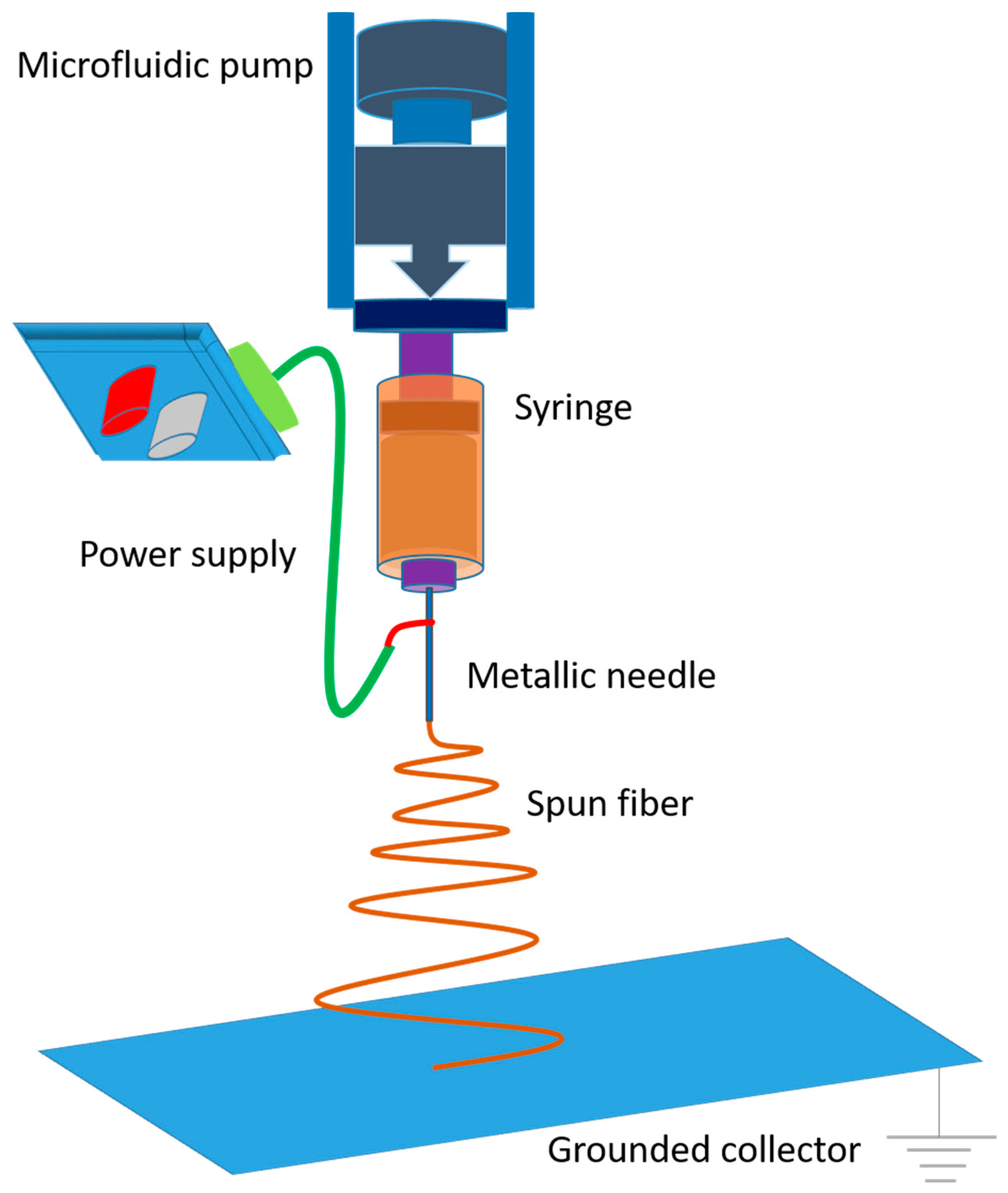
3. Electrospinning
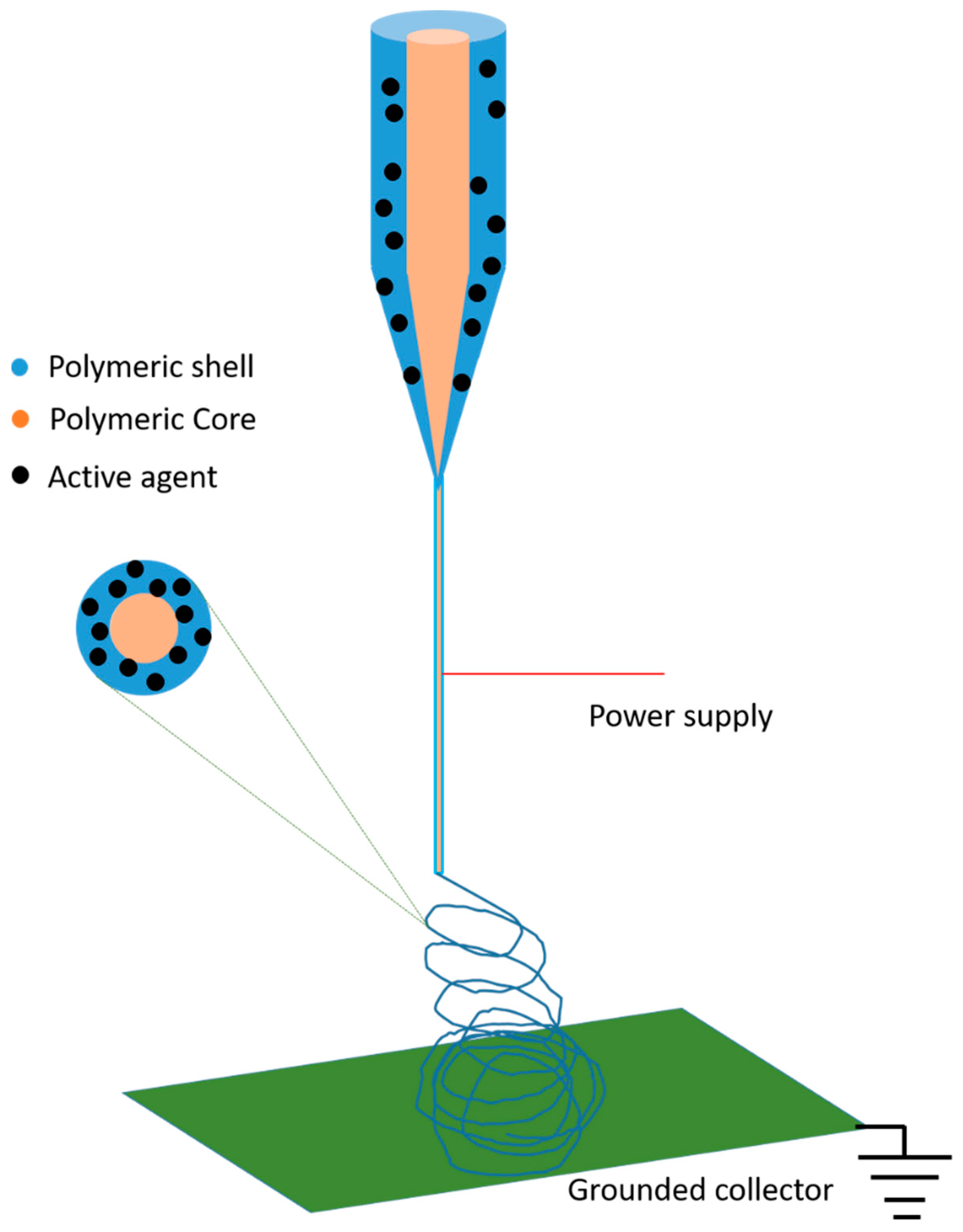
4. Core-Shell Nanofibers
5. Hollow and Porous Nanofibers
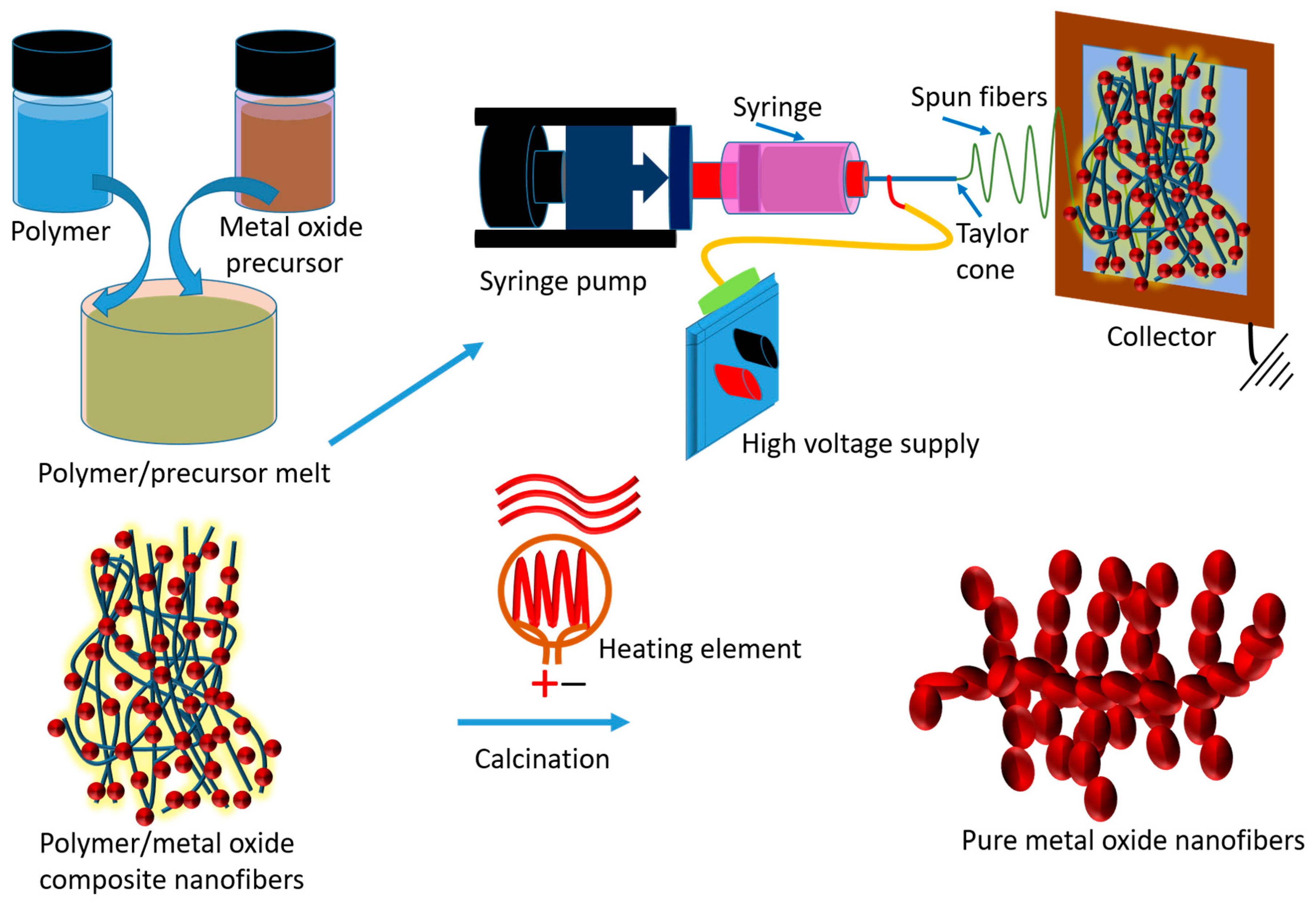
6. Metal Oxide Nanofibers
7. Photocatalysis
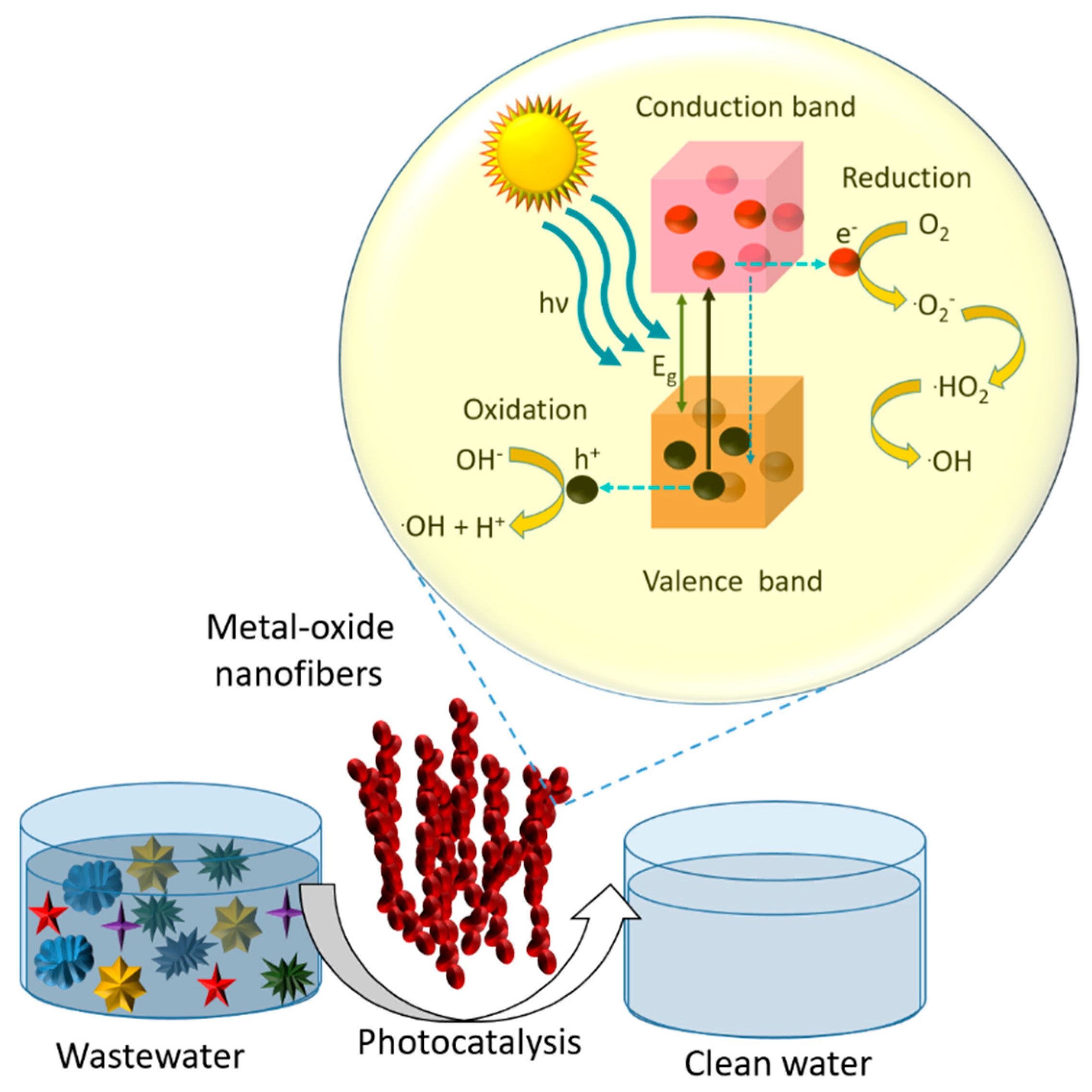
7.1. Mechanism and Kinetics of Photocatalysis by Pure Metal Oxide Nanofibers
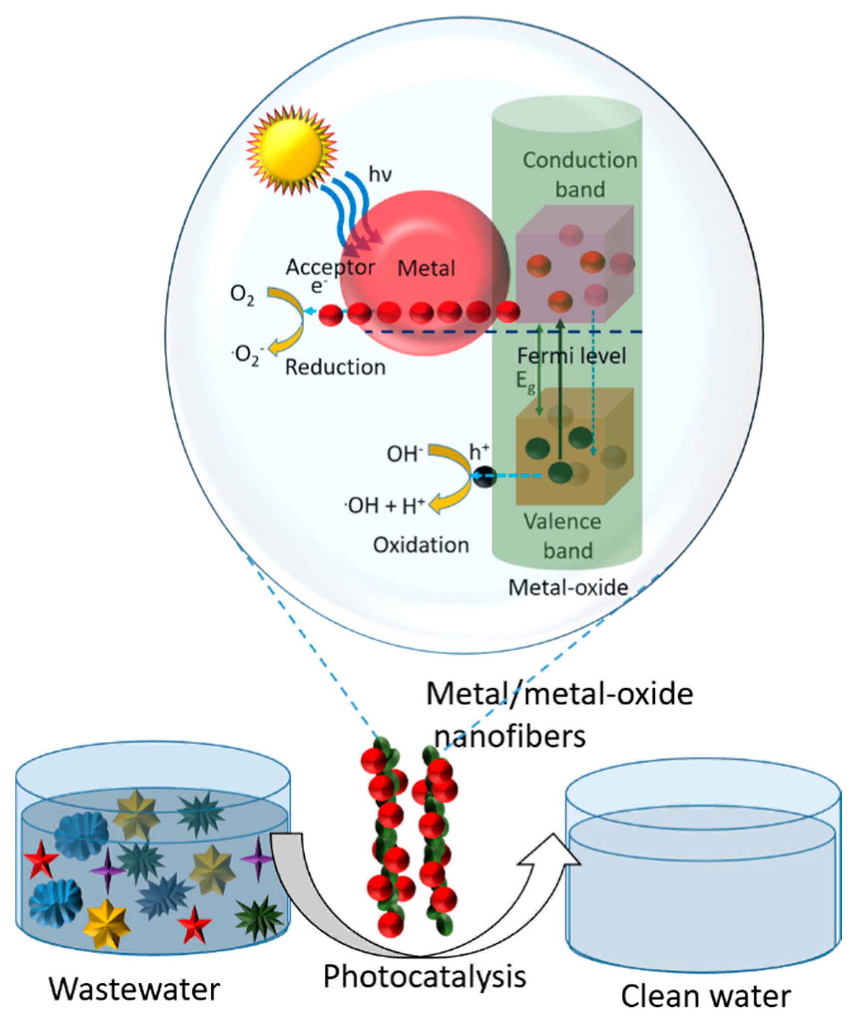
7.2. Mechanisms of Photocatalysis by Metal/Metal Oxide Composite Nanofibers
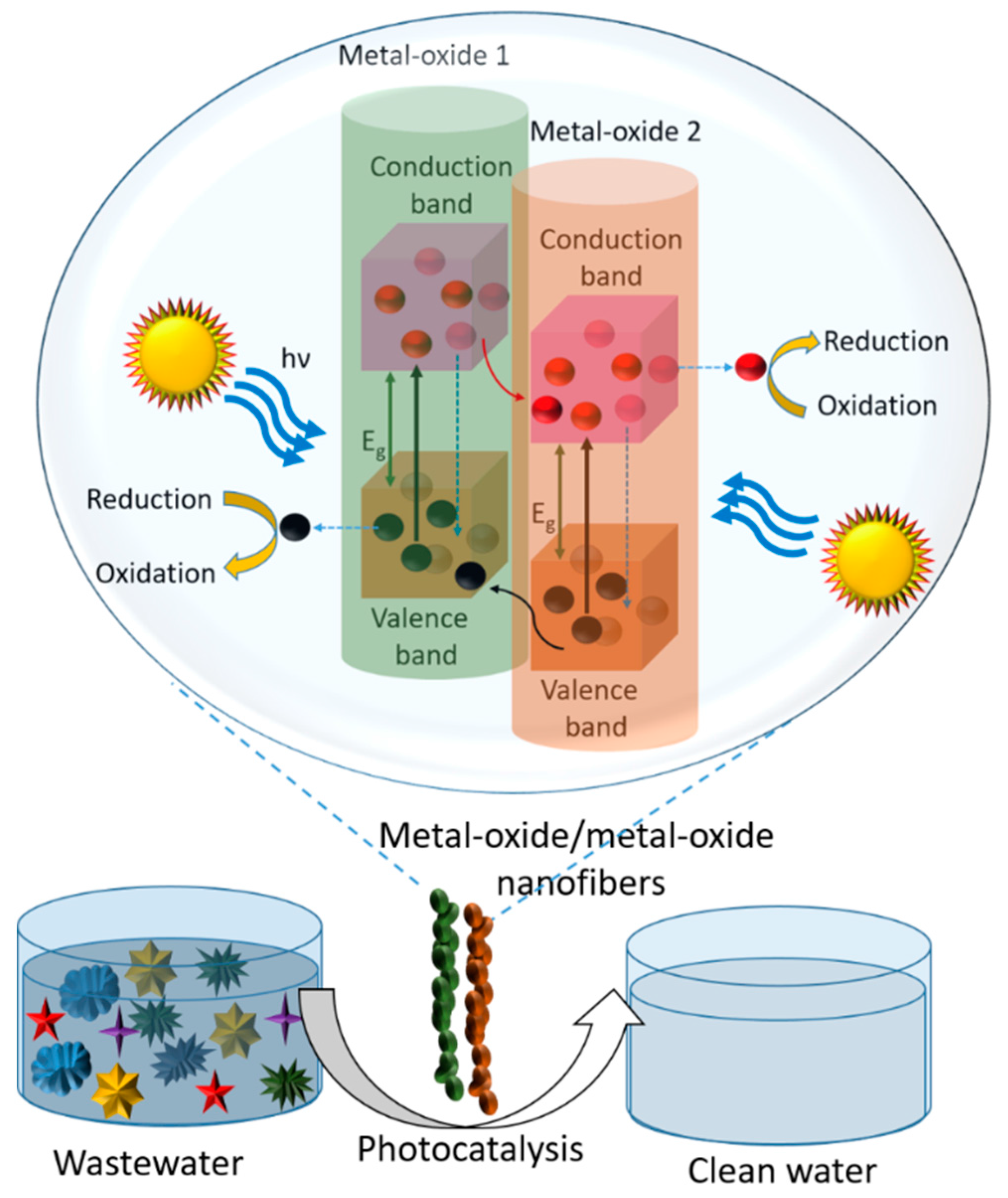
7.3. Mechanisms of Photocatalysis by Metal Oxide/Metal Oxide Composite Nanofibers
8. Environmental Remediation Application of Metal Oxide Nanofibers
8.1. Wastewater Treatment
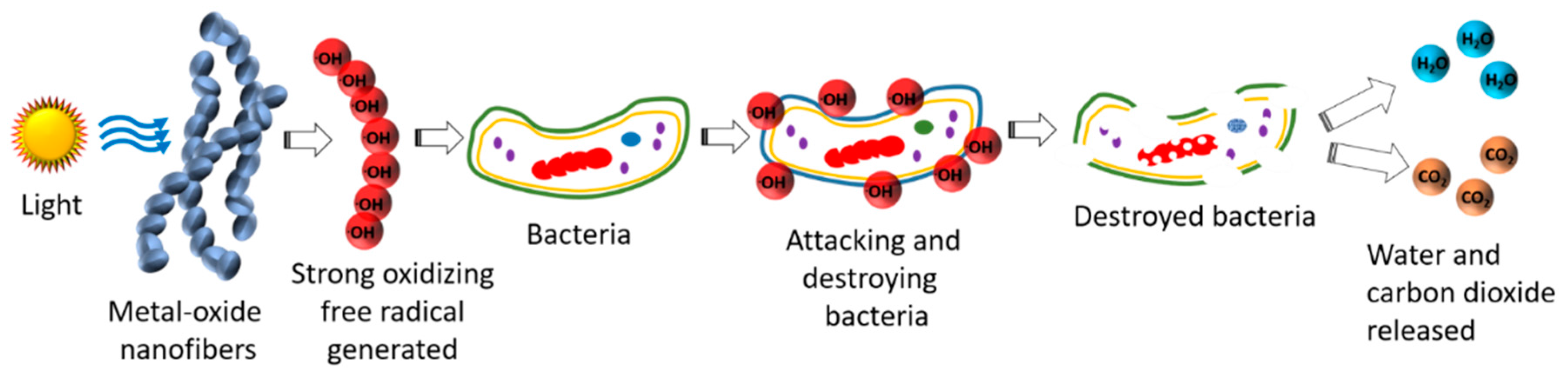
8.2. Water Disinfection and Air Cleansing
8.3. Other Applications
9. Recycling of Nanofiber Photocatalysts
10. Conclusions
Acknowledgments
Conflicts of Interest
References
- Kim, S.; Oh, K.; Lee, S.; Choi, S.; Lee, K. Study on secondary reaction and fate of hazardous chemicals by oxidants. Water Sci. Technol. 1997, 36, 325–331. [Google Scholar] [CrossRef]
- Echigo, S.; Yamada, H.; Matsui, S.; Kawanishi, S.; Shishida, K. Comparison between O3/VUV, O3/H2O2, VUV and O3 processes for the decomposition of organophosphoric acid triesters. Water Sci. Technol. 1996, 34, 81–88. [Google Scholar] [CrossRef]
- Vorontsov, A.V.; Dubovitskaya, V.P. Selectivity of photocatalytic oxidation of gaseous ethanol over pure and modified TiO2. J. Catal. 2004, 221, 102–109. [Google Scholar] [CrossRef]
- Hakki, A.; Dillert, R.; Bahnemann, D.W. Factors affecting the selectivity of the photocatalytic conversion of nitroaromatic compounds over TiO2 to valuable nitrogen-containing organic compounds. Phys. Chem. Chem. Phys. 2013, 15, 2992–3002. [Google Scholar] [CrossRef] [PubMed]
- Hu, J.Y.; Wang, Z.S.; Ng, W.J.; Ong, S.L. The effect of water treatment processes on the biological stability of potable water. Water Res. 1999, 33, 2587–2592. [Google Scholar] [CrossRef]
- Suri, R.P.S.; Liu, J.; Hand, D.W.; Crittenden, J.C.; Perram, D.L.; Mullins, M.E. Heterogeneous photocatalytic oxidation of hazardous organic contaminants in water. Water Environ. Res. 1993, 65, 665–673. [Google Scholar] [CrossRef]
- Liu, R.; Wang, P.; Wang, X.; Yu, H.; Yu, J. UV- and Visible-Light Photocatalytic Activity of Simultaneously Deposited and Doped Ag/Ag(I)-TiO2 Photocatalyst. J. Phys. Chem. C 2012, 116, 17721–17728. [Google Scholar] [CrossRef]
- Kanakaraju, D.; Glass, B.D.; Oelgemöller, M. Titanium dioxide photocatalysis for pharmaceutical wastewater treatment. Environ. Chem. Lett. 2014, 12, 27–47. [Google Scholar] [CrossRef]
- Chong, M.N.; Jin, B.; Chow, C.W.K.; Saint, C. Recent developments in photocatalytic water treatment technology: A review. Water Res. 2010, 44, 2997–3027. [Google Scholar] [CrossRef] [PubMed]
- Pincella, F.; Isozaki, K.; Miki, K. A visible light-driven plasmonic photocatalyst. Light Sci. Appl. 2014, 3, e133. [Google Scholar] [CrossRef]
- Anjum, M.; Miandad, R.; Waqas, M.; Gehany, F.; Barakat, M.A. Remediation of wastewater using various nano-materials. Arab. J. Chem. 2016. [Google Scholar] [CrossRef]
- Sugunan, A.; Guduru, V.K.; Uheida, A.; Toprak, M.S.; Muhammed, M. Radially Oriented ZnO Nanowires on Flexible Poly-l-Lactide Nanofibers for Continuous-Flow Photocatalytic Water Purification. J. Am. Ceram. Soc. 2010, 93, 3740–3744. [Google Scholar] [CrossRef]
- Burks, T.; Akthar, F.; Saleemi, M.; Avila, M.; Kiros, Y. ZnO-PLLA Nanofiber Nanocomposite for Continuous Flow Mode Purification of Water from Cr(VI). J. Environ. Public Health 2015, 2015, 1–7. [Google Scholar] [CrossRef] [PubMed]
- Singh, P.; Mondal, K.; Sharma, A. Reusable electrospun mesoporous ZnO nanofiber mats for photocatalytic degradation of polycyclic aromatic hydrocarbon dyes in wastewater. J. Colloid Interface Sci. 2013, 394, 208–215. [Google Scholar] [CrossRef] [PubMed]
- Mondal, K.; Bhattacharyya, S.; Sharma, A. Photocatalytic Degradation of Naphthalene by Electrospun Mesoporous Carbon-Doped Anatase TiO2 Nanofiber Mats. Ind. Eng. Chem. Res. 2014, 53, 18900–18909. [Google Scholar] [CrossRef]
- Hong, H.-J.; Sarkar, S.K.; Lee, B.-T. Formation of TiO2 nano fibers on a micro-channeled Al2O3–ZrO2/TiO2 porous composite membrane for photocatalytic filtration. J. Eur. Ceram. Soc. 2012, 32, 657–663. [Google Scholar] [CrossRef]
- Reddy, K.R.; Gomes, V.G.; Hassan, M. Carbon functionalized TiO2 nanofibers for high efficiency photocatalysis. Mater. Res. Express 2014, 1, 015012. [Google Scholar] [CrossRef]
- Singh, N.; Mondal, K.; Misra, M.; Sharma, A.; Gupta, R.K. Quantum dot sensitized electrospun mesoporous titanium dioxide hollow nanofibers for photocatalytic applications. RSC Adv. 2016, 6, 48109–48119. [Google Scholar] [CrossRef]
- Zhao, D.; He, Z.; Wang, G.; Wang, H.; Zhang, Q.; Li, Y. A novel efficient ZnO/Zn(OH)F nanofiber arrays-based versatile microfluidic system for the applications of photocatalysis and histidine-rich protein separation. Sens. Actuators B Chem. 2016, 229, 281–287. [Google Scholar] [CrossRef]
- Zhang, L.; Chen, P.; Gu, G.; Wu, Q.; Yao, W. Novel synthesis and photocatalytic performance of Ce1−xZrxO2/silica fiber. Appl. Surf. Sci. 2016, 382, 155–161. [Google Scholar] [CrossRef]
- Asif, S.A.B.; Khan, S.B.; Asiri, A.M. Visible light functioning photocatalyst based on Al2O3 doped Mn3O4 nanomaterial for the degradation of organic toxin. Nanoscale Res. Lett. 2015, 10. [Google Scholar] [CrossRef] [PubMed]
- Akhi, Y.; Irani, M.; Olya, M.E. Simultaneous degradation of phenol and paracetamol using carbon/MWCNT/Fe3O4 composite nanofibers during photo-like-Fenton process. J. Taiwan Inst. Chem. Eng. 2016, 63, 327–335. [Google Scholar] [CrossRef]
- Wang, J.; Yang, G.; Lyu, W.; Yan, W. Thorny TiO2 nanofibers: Synthesis, enhanced photocatalytic activity and supercapacitance. J. Alloys Compd. 2016, 659, 138–145. [Google Scholar] [CrossRef]
- Qin, D.; Lu, W.; Wang, X.; Li, N.; Chen, X.; Zhu, Z.; Chen, W. Graphitic Carbon Nitride from Burial to Re-emergence on Polyethylene Terephthalate Nanofibers as an Easily Recycled Photocatalyst for Degrading Antibiotics under Solar Irradiation. ACS Appl. Mater. Interfaces 2016, 8, 25962–25970. [Google Scholar] [CrossRef] [PubMed]
- Wongaree, M.; Chiarakorn, S.; Chuangchote, S.; Sagawa, T. Photocatalytic performance of electrospun CNT/TiO2 nanofibers in a simulated air purifier under visible light irradiation. Environ. Sci. Pollut. Res. 2016, 23, 21395–21406. [Google Scholar] [CrossRef] [PubMed]
- Ma, Z.; Hu, Z.; He, X.; Fang, Z.; Li, Y.; Qiu, J. Nano-Bi2WO6 functionalized flexible SiO2 fibrous film for water purification. Appl. Surf. Sci. 2016, 360, 174–183. [Google Scholar] [CrossRef]
- Hu, Z.; Ma, Z.; He, X.; Liao, C.; Li, Y.; Qiu, J. Preparation and characterization of flexible and thermally stable CuO nanocrystal-decorated SiO2 nanofibers. J. Sol-Gel Sci. Technol. 2015, 76, 492–500. [Google Scholar] [CrossRef]
- Ma, D.; Zhang, Y.; Gao, M.; Xin, Y.; Wu, J.; Bao, N. RGO/InVO4 hollowed-out nanofibers: Electrospinning synthesis and its application in photocatalysis. Appl. Surf. Sci. 2015, 353, 118–126. [Google Scholar] [CrossRef]
- Xie, J.; Yang, Y.; He, H.; Cheng, D.; Mao, M.; Jiang, Q.; Song, L.; Xiong, J. Facile synthesis of hierarchical Ag3PO4/TiO2 nanofiber heterostructures with highly enhanced visible light photocatalytic properties. Appl. Surf. Sci. 2015, 355, 921–929. [Google Scholar] [CrossRef]
- Ofori, F.A.; Sheikh, F.A.; Appiah-Ntiamoah, R.; Yang, X.; Kim, H. A Simple Method of Electrospun Tungsten Trioxide Nanofibers with Enhanced Visible-Light Photocatalytic Activity. Nano-Micro Lett. 2015, 7, 291–297. [Google Scholar] [CrossRef]
- Zhao, Y.; Tao, C.; Xiao, G.; Wei, G.; Li, L.; Liu, C.; Su, H. Controlled synthesis and photocatalysis of sea urchin-like Fe3O4@TiO2@Ag nanocomposites. Nanoscale 2016, 8, 5313–5326. [Google Scholar] [CrossRef] [PubMed]
- Liu, C.; Meng, D.; Li, Y.; Wang, L.; Liu, Y.; Luo, S. Hierarchical architectures of ZnS–In2S3 solid solution onto TiO2 nanofibers with high visible-light photocatalytic activity. J. Alloys Compd. 2015, 624, 44–52. [Google Scholar] [CrossRef]
- Chen, Y.-Y.; Kuo, C.-C.; Chen, B.-Y.; Chiu, P.-C.; Tsai, P.-C. Multifunctional polyacrylonitrile-ZnO/Ag electrospun nanofiber membranes with various ZnO morphologies for photocatalytic, UV-shielding, and antibacterial applications. J. Polym. Sci. Part B Polym. Phys. 2015, 53, 262–269. [Google Scholar] [CrossRef]
- Liang, P.; Zhang, L.; Zhao, X.; Li, J.; Liu, L.; Cai, R.; Yang, D.; Umar, A. Synthesis of ZnFe2O4/TiO2 Composite Nanofibers with Enhanced Photoelectrochemical Activity. Sci. Adv. Mater. 2015, 7, 295–300. [Google Scholar] [CrossRef]
- Zhang, M.; Liu, Y.; Li, L.; Gao, H.; Zhang, X. BiOCl nanosheet/Bi4Ti3O12 nanofiber heterostructures with enhanced photocatalytic activity. Catal. Commun. 2015, 58, 122–126. [Google Scholar] [CrossRef]
- Wang, X.; Gao, J.; Xu, B.; Hua, T.; Xia, H. ZnO nanorod/nickel phthalocyanine hierarchical hetero-nanostructures with superior visible light photocatalytic properties assisted by H2O2. RSC Adv. 2015, 5, 87233–87240. [Google Scholar] [CrossRef]
- Kushwaha, H.S.; Thomas, P.; Vaish, R. Polyaniline/CaCu3Ti4O12 nanofiber composite with a synergistic effect on visible light photocatalysis. RSC Adv. 2015, 5, 87241–87250. [Google Scholar] [CrossRef]
- Galkina, O.L.; Önneby, K.; Huang, P.; Ivanov, V.K.; Agafonov, A.V.; Seisenbaeva, G.A.; Kessler, V.G. Antibacterial and photochemical properties of cellulose nanofiber–titania nanocomposites loaded with two different types of antibiotic medicines. J. Mater. Chem. B 2015, 3, 7125–7134. [Google Scholar] [CrossRef]
- Liu, M.; Wang, Y.; Cheng, Z.; Song, L.; Zhang, M.; Hu, M.; Li, J. Function of NaOH hydrolysis in electrospinning ZnO nanofibers via using polylactide as templates. Mater. Sci. Eng. B 2014, 187, 89–95. [Google Scholar] [CrossRef]
- Kang, H.-J.; Shin, S.-H.; Jo, W.-K.; Chun, H.-H. Visible Light- or UV-Activated Carbon Nanotube-TiO2 Composite Nanofibers for Indoor BTEX Purification. Asian J. Chem. 2014, 26. [Google Scholar] [CrossRef]
- Kang, H.-J.; Shin, S.-H.; Chun, H.-H.; Jo, W.-K. Combined Nanofibers of Carbon Nanotube, Titania and Polymer Substrate for Oxidation of Toluene and Isopropyl Alcohol. Asian J. Chem. 2014, 26. [Google Scholar] [CrossRef]
- Szatmáry, L.; Šubrt, J.; Kalousek, V.; Mosinger, J.; Lang, K. Low-temperature deposition of anatase on nanofiber materials for photocatalytic NOx removal. Catal. Today 2014, 230, 74–78. [Google Scholar] [CrossRef]
- Ma, D.; Xin, Y.; Gao, M.; Wu, J. Fabrication and photocatalytic properties of cationic and anionic S-doped TiO2 nanofibers by electrospinning. Appl. Catal. B Environ. 2014, 147, 49–57. [Google Scholar] [CrossRef]
- Liu, Z.; Miao, Y.-E.; Liu, M.; Ding, Q.; Tjiu, W.W.; Cui, X.; Liu, T. Flexible polyaniline-coated TiO2/SiO2 nanofiber membranes with enhanced visible-light photocatalytic degradation performance. J. Colloid Interface Sci. 2014, 424, 49–55. [Google Scholar] [CrossRef] [PubMed]
- Lu, M.; Shao, C.; Wang, K.; Lu, N.; Zhang, X.; Zhang, P.; Zhang, M.; Li, X.; Liu, Y. p-MoO3 Nanostructures/n-TiO2 Nanofiber Heterojunctions: Controlled Fabrication and Enhanced Photocatalytic Properties. ACS Appl. Mater. Interfaces 2014, 6, 9004–9012. [Google Scholar] [CrossRef] [PubMed]
- Zhang, P.; Shao, C.; Zhang, Z.; Zhang, M.; Mu, J.; Guo, Z.; Sun, Y.; Liu, Y. Core/shell nanofibers of TiO2@carbon embedded by Ag nanoparticles with enhanced visible photocatalytic activity. J. Mater. Chem. 2011, 21, 17746. [Google Scholar] [CrossRef]
- Mu, J.; Shao, C.; Guo, Z.; Zhang, Z.; Zhang, M.; Zhang, P.; Chen, B.; Liu, Y. High Photocatalytic Activity of ZnO−Carbon Nanofiber Heteroarchitectures. ACS Appl. Mater. Interfaces 2011, 3, 590–596. [Google Scholar] [CrossRef] [PubMed]
- Galland, S.; Andersson, R.L.; Salajková, M.; Ström, V.; Olsson, R.T.; Berglund, L.A. Cellulose nanofibers decorated with magnetic nanoparticles—Synthesis, structure and use in magnetized high toughness membranes for a prototype loudspeaker. J. Mater. Chem. C 2013, 1, 7963. [Google Scholar] [CrossRef]
- Dzenis, Y. Materials Science: Structural Nanocomposites. Science 2008, 319, 419–420. [Google Scholar] [CrossRef] [PubMed]
- Ren, Y.; Wang, S.; Liu, R.; Dai, J.; Liu, X.; Yu, J. A novel route towards well-dispersed short nanofibers and nanoparticles via electrospinning. RSC Adv. 2016, 6, 30139–30147. [Google Scholar] [CrossRef]
- Tan, E.P.S.; Lim, C.T. Mechanical characterization of nanofibers—A review. Compos. Sci. Technol. 2006, 66, 1102–1111. [Google Scholar] [CrossRef]
- Zhang, T.; Wu, X.; Luo, T. Polymer Nanofibers with Outstanding Thermal Conductivity and Thermal Stability: Fundamental Linkage between Molecular Characteristics and Macroscopic Thermal Properties. J. Phys. Chem. C 2014, 118, 21148–21159. [Google Scholar] [CrossRef]
- Lin, T.; Lukas, D.; Bhat, G.S. Nanofiber Manufacture, Properties, and Applications. J. Nanomater. 2013, 2013, 1. [Google Scholar] [CrossRef]
- Manea, L.R.; Hristian, L.; Leon, A.L.; Popa, A. Recent advances of basic materials to obtain electrospun polymeric nanofibers for medical applications. IOP Conf. Ser. Mater. Sci. Eng. 2016, 145, 032006. [Google Scholar] [CrossRef]
- Beachley, V.; Wen, X. Effect of electrospinning parameters on the nanofiber diameter and length. Mater. Sci. Eng. C 2009, 29, 663–668. [Google Scholar] [CrossRef] [PubMed]
- Nayak, R.; Padhye, R.; Kyratzis, I.L.; Truong, Y.B.; Arnold, L. Recent advances in nanofibre fabrication techniques. Text. Res. J. 2011, 82, 129–147. [Google Scholar] [CrossRef]
- Moon, S.; Gil, M.; Lee, K.J. Syringeless Electrospinning toward Versatile Fabrication of Nanofiber Web. Sci. Rep. 2017, 7, 41424. [Google Scholar] [CrossRef] [PubMed]
- Nakielski, P.; Pawłowska, S.; Pierini, F.; Liwińska, W.; Hejduk, P.; Zembrzycki, K.; Zabost, E.; Kowalewski, T.A. Hydrogel Nanofilaments via Core-Shell Electrospinning. PLoS ONE 2015, 10, e0129816. [Google Scholar]
- Reneker, D.H.; Yarin, A.L. Electrospinning jets and polymer nanofibers. Polymer 2008, 49, 2387–2425. [Google Scholar] [CrossRef]
- Shao, H.; Ma, Q.; Dong, X.; Yu, W.; Yang, M.; Yang, Y.; Wang, J.; Liu, G. Electrospun Flexible Coaxial Nanoribbons Endowed With Tuned and Simultaneous Fluorescent Color-Electricity-Magnetism Trifunctionality. Sci. Rep. 2015, 5, 14052. [Google Scholar] [CrossRef] [PubMed]
- Lin, T.; Wang, H.; Wang, X. Self-Crimping Bicomponent Nanofibers Electrospun from Polyacrylonitrile and Elastomeric Polyurethane. Adv. Mater. 2005, 17, 2699–2703. [Google Scholar] [CrossRef]
- De Jong, K.P.; Geus, J.W. Carbon Nanofibers: Catalytic Synthesis and Applications. Catal. Rev. 2000, 42, 481–510. [Google Scholar] [CrossRef]
- Mirjalili, M.; Zohoori, S. Review for application of electrospinning and electrospun nanofibers technology in textile industry. J. Nanostruct. Chem. 2016, 6, 207–213. [Google Scholar] [CrossRef]
- Ding, B.; Wang, M.; Yu, J.; Sun, G. Gas Sensors Based on Electrospun Nanofibers. Sensors 2009, 9, 1609–1624. [Google Scholar] [CrossRef] [PubMed]
- Thavasi, V.; Singh, G.; Ramakrishna, S. Electrospun nanofibers in energy and environmental applications. Energy Environ. Sci. 2008, 1, 205. [Google Scholar] [CrossRef]
- Daniele, M.A.; Boyd, D.A.; Adams, A.A.; Ligler, F.S. Microfluidic Strategies for Design and Assembly of Microfibers and Nanofibers with Tissue Engineering and Regenerative Medicine Applications. Adv. Healthc. Mater. 2015, 4, 11–28. [Google Scholar] [CrossRef] [PubMed]
- Teo, W.E.; Ramakrishna, S. A review on electrospinning design and nanofibre assemblies. Nanotechnology 2006, 17, R89. [Google Scholar] [CrossRef] [PubMed]
- Murugan, R.; Ramakrishna, S. Nano-Featured Scaffolds for Tissue Engineering: A Review of Spinning Methodologies. Tissue Eng. 2006, 12, 435–447. [Google Scholar] [CrossRef] [PubMed]
- Khajavi, R.; Abbasipour, M. Electrospinning as a versatile method for fabricating coreshell, hollow and porous nanofibers. Sci. Iran. 2012, 19, 2029–2034. [Google Scholar] [CrossRef]
- Reneker, D.H.; Chun, I. Nanometre diameter fibres of polymer, produced by electrospinning. Nanotechnology 1996, 7, 216. [Google Scholar] [CrossRef]
- Zhou, Y.; Freitag, M.; Hone, J.; Staii, C.; Johnson, A.T.; Pinto, N.J.; MacDiarmid, A.G. Fabrication and electrical characterization of polyaniline-based nanofibers with diameter below 30 nm. Appl. Phys. Lett. 2003, 83, 3800–3802. [Google Scholar] [CrossRef]
- Pillay, V.; Dott, C.; Choonara, Y.E.; Tyagi, C.; Tomar, L.; Kumar, P.; du Toit, L.C.; Ndesendo, V.M.K. A Review of the Effect of Processing Variables on the Fabrication of Electrospun Nanofibers for Drug Delivery Applications. J. Nanomater. 2013, 2013, 1–22. [Google Scholar] [CrossRef]
- Bae, H.-S.; Haider, A.; Selim, K.M.K.; Kang, D.-Y.; Kim, E.-J.; Kang, I.-K. Fabrication of highly porous PMMA electrospun fibers and their application in the removal of phenol and iodine. J. Polym. Res. 2013, 20. [Google Scholar] [CrossRef]
- Haider, S.; Al-Zeghayer, Y.; Ahmed Ali, F.A.; Haider, A.; Mahmood, A.; Al-Masry, W.A.; Imran, M.; Aijaz, M.O. Highly aligned narrow diameter chitosan electrospun nanofibers. J. Polym. Res. 2013, 20. [Google Scholar] [CrossRef]
- Sun, Z.; Zussman, E.; Yarin, A.L.; Wendorff, J.H.; Greiner, A. Compound Core–Shell Polymer Nanofibers by Co-Electrospinning. Adv. Mater. 2003, 15, 1929–1932. [Google Scholar] [CrossRef]
- Elahi, M.F.; Lu, W. Core-shell Fibers for Biomedical Applications—A Review. J. Bioeng. Biomed. Sci. 2013, 3. [Google Scholar] [CrossRef]
- Yarin, A.L.; Zussman, E.; Wendorff, J.H.; Greiner, A. Material encapsulation and transport in core–shell micro/nanofibers, polymer and carbon nanotubes and micro/nanochannels. J. Mater. Chem. 2007, 17, 2585–2599. [Google Scholar] [CrossRef]
- Agarwal, S.; Wendorff, J.H.; Greiner, A. Use of electrospinning technique for biomedical applications. Polymer 2008, 49, 5603–5621. [Google Scholar] [CrossRef]
- Li, D.; Xia, Y. Electrospinning of Nanofibers: Reinventing the Wheel? Adv. Mater. 2004, 16, 1151–1170. [Google Scholar] [CrossRef]
- Dalton, P.D.; Klee, D.; Möller, M. Electrospinning with dual collection rings. Polymer 2005, 46, 611–614. [Google Scholar] [CrossRef]
- Hou, H.; Jun, Z.; Reuning, A.; Schaper, A.; Wendorff, J.H.; Greiner, A. Poly(p-xylylene) Nanotubes by Coating and Removal of Ultrathin Polymer Template Fibers. Macromolecules 2002, 35, 2429–2431. [Google Scholar] [CrossRef]
- Bognitzki, M.; Frese, T.; Steinhart, M.; Greiner, A.; Wendorff, J.H.; Schaper, A.; Hellwig, M. Preparation of fibers with nanoscaled morphologies: Electrospinning of polymer blends. Polym. Eng. Sci. 2001, 41, 982–989. [Google Scholar] [CrossRef]
- Zhan, S.; Chen, D.; Jiao, X.; Tao, C. Long TiO2 Hollow Fibers with Mesoporous Walls: Sol−Gel Combined Electrospun Fabrication and Photocatalytic Properties. J. Phys. Chem. B 2006, 110, 11199–11204. [Google Scholar] [CrossRef] [PubMed]
- Zhan, S.; Chen, D.; Jiao, X.; Liu, S. Facile fabrication of long α-Fe2O3, α-Fe and γ-Fe2O3 hollow fibers using sol–gel combined co-electrospinning technology. J. Colloid Interface Sci. 2007, 308, 265–270. [Google Scholar] [CrossRef] [PubMed]
- Gu, Y.; Jian, F. Hollow LiNi0.8Co0.1Mn0.1O2−MgO Coaxial Fibers: Sol−Gel Method Combined with Co-electrospun Preparation and Electrochemical Properties. J. Phys. Chem. C 2008, 112, 20176–20180. [Google Scholar] [CrossRef]
- Rahmathullah, A.M.; Jason Robinette, E.; Chen, H.; Elabd, Y.A.; Palmese, G.R. Plasma assisted synthesis of hollow nanofibers using electrospun sacrificial templates. Nucl. Instrum. Methods Phys. Res. Sect. B 2007, 265, 23–30. [Google Scholar] [CrossRef]
- Ge, L.; Pan, C.; Chen, H.; Wang, X.; Wang, C.; Gu, Z. The fabrication of hollow multilayered polyelectrolyte fibrous mats and its morphology study. Colloids Surf. Physicochem. Eng. Asp. 2007, 293, 272–277. [Google Scholar] [CrossRef]
- Zhang, T.; Ge, L.; Wang, X.; Gu, Z. Hollow TiO2 containing multilayer nanofibers with enhanced photocatalytic activity. Polymer 2008, 49, 2898–2902. [Google Scholar] [CrossRef]
- Cui, Q.; Dong, X.; Wang, J.; Li, M. Direct fabrication of cerium oxide hollow nanofibers by electrospinning. J. Rare Earths 2008, 26, 664–669. [Google Scholar] [CrossRef]
- Meng, B.; Tan, X.; Meng, X.; Qiao, S.; Liu, S. Porous and dense Ni hollow fibre membranes. J. Alloys Compd. 2009, 470, 461–464. [Google Scholar] [CrossRef]
- Sundarrajan, S.; Tan, K.L.; Lim, S.H.; Ramakrishna, S. Electrospun Nanofibers for Air Filtration Applications. Procedia Eng. 2014, 75, 159–163. [Google Scholar] [CrossRef]
- Zainoodin, A.M.; Kamarudin, S.K.; Masdar, M.S.; Daud, W.R.W.; Mohamad, A.B.; Sahari, J. High power direct methanol fuel cell with a porous carbon nanofiber anode layer. Appl. Energy 2014, 113, 946–954. [Google Scholar] [CrossRef]
- Patel, A.C.; Li, S.; Wang, C.; Zhang, W.; Wei, Y. Electrospinning of Porous Silica Nanofibers Containing Silver Nanoparticles for Catalytic Applications. Chem. Mater. 2007, 19, 1231–1238. [Google Scholar] [CrossRef]
- Smith, I.O.; Liu, X.H.; Smith, L.A.; Ma, P.X. Nanostructured polymer scaffolds for tissue engineering and regenerative medicine. Wiley Interdiscip. Rev. Nanomed. Nanobiotechnol. 2009, 1, 226–236. [Google Scholar] [CrossRef] [PubMed]
- Loh, Q.L.; Choong, C. Three-Dimensional Scaffolds for Tissue Engineering Applications: Role of Porosity and Pore Size. Tissue Eng. Part B Rev. 2013, 19, 485–502. [Google Scholar] [CrossRef] [PubMed]
- Chou, S.-F.; Carson, D.; Woodrow, K.A. Current strategies for sustaining drug release from electrospun nanofibers. J. Controlled Release 2015, 220, 584–591. [Google Scholar] [CrossRef] [PubMed]
- Mondal, K.; Ali, M.A.; Singh, C.; Sumana, G.; Malhotra, B.D.; Sharma, A. Highly sensitive porous carbon and metal/carbon conducting nanofiber based enzymatic biosensors for triglyceride detection. Sens. Actuators B Chem. 2017, 246, 202–214. [Google Scholar] [CrossRef]
- Chung, H.J.; Park, T.G. Surface engineered and drug releasing pre-fabricated scaffolds for tissue engineering. Matrices Scaffolds Drug Deliv. Tissue Eng. 2007, 59, 249–262. [Google Scholar] [CrossRef] [PubMed]
- Nayani, K.; Katepalli, H.; Sharma, C.S.; Sharma, A.; Patil, S.; Venkataraghavan, R. Electrospinning Combined with Nonsolvent-Induced Phase Separation To Fabricate Highly Porous and Hollow Submicrometer Polymer Fibers. Ind. Eng. Chem. Res. 2012, 51, 1761–1766. [Google Scholar] [CrossRef]
- Ramakrishna, S. An Introduction to Electrospinning and Nanofibers; World Scientific: Singapore; Hackensack, NJ, USA, 2005. [Google Scholar]
- Barhate, R.; Ramakrishna, S. Nanofibrous filtering media: Filtration problems and solutions from tiny materials. J. Membr. Sci. 2007, 296, 1–8. [Google Scholar] [CrossRef]
- Peng, M.; Li, D.; Shen, L.; Chen, Y.; Zheng, Q.; Wang, H. Nanoporous Structured Submicrometer Carbon Fibers Prepared via Solution Electrospinning of Polymer Blends. Langmuir 2006, 22, 9368–9374. [Google Scholar] [CrossRef] [PubMed]
- Qi, Z.; Yu, H.; Chen, Y.; Zhu, M. Highly porous fibers prepared by electrospinning a ternary system of nonsolvent/solvent/poly(l-lactic acid). Mater. Lett. 2009, 63, 415–418. [Google Scholar] [CrossRef]
- Mondal, K.; Sharma, A. Recent advances in electrospun metal-oxide nanofiber based interfaces for electrochemical biosensing. RSC Adv. 2016, 6, 94595–94616. [Google Scholar] [CrossRef]
- Mondal, K.; Ali, M.A.; Agrawal, V.V.; Malhotra, B.D.; Sharma, A. Highly Sensitive Biofunctionalized Mesoporous Electrospun TiO2 Nanofiber Based Interface for Biosensing. ACS Appl. Mater. Interfaces 2014, 6, 2516–2527. [Google Scholar] [CrossRef] [PubMed]
- Ali, M.A.; Mondal, K.; Singh, C.; Dhar Malhotra, B.; Sharma, A. Anti-epidermal growth factor receptor conjugated mesoporous zinc oxide nanofibers for breast cancer diagnostics. Nanoscale 2015, 7, 7234–7245. [Google Scholar] [CrossRef] [PubMed]
- Park, S.-H.; Jung, H.-R.; Lee, W.-J. Hollow activated carbon nanofibers prepared by electrospinning as counter electrodes for dye-sensitized solar cells. Electrochimica Acta 2013, 102, 423–428. [Google Scholar] [CrossRef]
- Crespy, D.; Friedemann, K.; Popa, A.-M. Colloid-Electrospinning: Fabrication of Multicompartment Nanofibers by the Electrospinning of Organic or/and Inorganic Dispersions and Emulsions. Macromol. Rapid Commun. 2012, 33, 1978–1995. [Google Scholar] [CrossRef] [PubMed]
- Shi, X.; Zhou, W.; Ma, D.; Ma, Q.; Bridges, D.; Ma, Y.; Hu, A. Electrospinning of Nanofibers and Their Applications for Energy Devices. J. Nanomater. 2015, 2015, 1–20. [Google Scholar] [CrossRef]
- Şimşek, M.; Rzayev, Z.M.O.; Bunyatova, U. Multifunctional electroactive electrospun nanofiber structures from water solution blends of PVA/ODA–MMT and poly(maleic acid-alt-acrylic acid): Effects of Ag, organoclay, structural rearrangement and NaOH doping factors. Adv. Nat. Sci. Nanosci. Nanotechnol. 2016, 7, 025009. [Google Scholar] [CrossRef]
- Li, L.; Meyer, W.H.; Wegner, G.; Wohlfahrt-Mehrens, M. Synthesis of Submicrometer-Sized Electrochemically Active Lithium Cobalt Oxide via a Polymer Precursor. Adv. Mater. 2005, 17, 984–988. [Google Scholar] [CrossRef]
- Lu, G.; Lieberwirth, I.; Wegner, G. A General Polymer-Based Process to Prepare Mixed Metal Oxides: The Case of Zn1-xMgxO Nanoparticles. J. Am. Chem. Soc. 2006, 128, 15445–15450. [Google Scholar] [CrossRef] [PubMed]
- Qin, D.; Gu, A.; Liang, G.; Yuan, L. A facile method to prepare zirconia electrospun fibers with different morphologies and their novel composites based on cyanate ester resin. RSC Adv. 2012, 2, 1364–1372. [Google Scholar] [CrossRef]
- Ko, J.-B.; Lee, S.W.; Kim, D.E.; Kim, Y.U.; Li, G.; Lee, S.G.; Chang, T.-S.; Kim, D.; Joo, Y.L. Fabrication of SiO2-ZrO2 composite fiber mats via electrospinning. J. Porous Mater. 2006, 13, 325–330. [Google Scholar] [CrossRef]
- Qin, D.; Liang, G.; Gu, A.; Yuan, L. Fabrication of SiO2 covered ZrO2 electrospun fibres with controllable structure and their novel high-performance composites with outstanding thermal, mechanical and dielectric properties. J. Compos. Mater. 2014, 48, 3201–3214. [Google Scholar] [CrossRef]
- Jiang, Y.; Zhang, Y.; Bai, J.; Ma, Z.; Cui, J. Facile Synthesis via Electrospinning of a Tetraethoxysilane/Polyvinylpyrrolidone Sol and Characterization of Ultrafine Crystalline SiO2 Nanofibers. J. Macromol. Sci. Part B 2014, 53, 383–390. [Google Scholar] [CrossRef]
- Chen, Y.; Zhang, Z.; Yu, J.; Guo, Z.-X. Poly(methyl methacrylate)/silica nanocomposite fibers by electrospinning. J. Polym. Sci. Part B Polym. Phys. 2009, 47, 1211–1218. [Google Scholar] [CrossRef]
- Friedemann, K.; Corrales, T.; Kappl, M.; Landfester, K.; Crespy, D. Facile and Large-Scale Fabrication of Anisometric Particles from Fibers Synthesized by Colloid-Electrospinning. Small 2012, 8, 144–153. [Google Scholar] [CrossRef] [PubMed]
- Kanehata, M.; Ding, B.; Shiratori, S. Nanoporous ultra-high specific surface inorganic fibres. Nanotechnology 2007, 18, 315602. [Google Scholar] [CrossRef]
- Horzum, N.; Taşçıoglu, D.; Okur, S.; Demir, M.M. Humidity sensing properties of ZnO-based fibers by electrospinning. Talanta 2011, 85, 1105–1111. [Google Scholar] [CrossRef] [PubMed]
- Imran, Z.; Rasool, K.; Batool, S.S.; Ahmad, M.; Rafiq, M.A. Effect of different electrodes on the transport properties of ZnO nanofibers under humid environment. AIP Adv. 2015, 5, 117214. [Google Scholar] [CrossRef]
- Subjalearndee, N.; Intasanta, V. Thermal relaxation in combination with fiberglass confined interpenetrating networks: A key calcination process for as-desired free standing metal oxide nanofibrous membranes. RSC Adv. 2016, 6, 86798–86807. [Google Scholar] [CrossRef]
- Lim, J.-M.; Moon, J.H.; Yi, G.-R.; Heo, C.-J.; Yang, S.-M. Fabrication of One-Dimensional Colloidal Assemblies from Electrospun Nanofibers. Langmuir 2006, 22, 3445–3449. [Google Scholar] [CrossRef] [PubMed]
- Li, D.; Xia, Y. Fabrication of Titania Nanofibers by Electrospinning. Nano Lett. 2003, 3, 555–560. [Google Scholar] [CrossRef]
- Kim, J.-H.; Yoo, S.-J.; Kwak, D.-H.; Jung, H.-J.; Kim, T.-Y.; Park, K.-H.; Lee, J.-W. Characterization and application of electrospun alumina nanofibers. Nanoscale Res. Lett. 2014, 9, 44. [Google Scholar] [CrossRef] [PubMed]
- Calza, P.; Minero, C.; Pelizzetti, E. Photocatalytically Assisted Hydrolysis of Chlorinated Methanes under Anaerobic Conditions. Environ. Sci. Technol. 1997, 31, 2198–2203. [Google Scholar] [CrossRef]
- Davis, A.P.; Green, D.L. Photocatalytic Oxidation of Cadmium-EDTA with Titanium Dioxide. Environ. Sci. Technol. 1999, 33, 609–617. [Google Scholar] [CrossRef]
- Schmelling, D.C.; Gray, K.A.; Kamat, P.V. The influence of solution matrix on the photocatalytic degradation of TNT in TiO2 slurries. Water Res. 1997, 31, 1439–1447. [Google Scholar] [CrossRef]
- Topalov, A.; Molnár-Gábor, D.; Csanádi, J. Photocatalytic oxidation of the fungicide metalaxyl dissolved in water over TiO2. Water Res. 1999, 33, 1371–1376. [Google Scholar] [CrossRef]
- Ku, Y.; Leu, R.-M.; Lee, K.-C. Decomposition of 2-chlorophenol in aqueous solution by UV irradiation with the presence of titanium dioxide. Water Res. 1996, 30, 2569–2578. [Google Scholar] [CrossRef]
- Serpone, N.; Emeline, A.V. Suggested terms and definitions in photocatalysis and radiocatalysis. Int. J. Photoenergy 2002, 4, 91–131. [Google Scholar] [CrossRef]
- Agustina, T.E.; Ang, H.M.; Vareek, V.K. A review of synergistic effect of photocatalysis and ozonation on wastewater treatment. J. Photochem. Photobiol. C Photochem. Rev. 2005, 6, 264–273. [Google Scholar] [CrossRef]
- Legrini, O.; Oliveros, E.; Braun, A.M. Photochemical processes for water treatment. Chem. Rev. 1993, 93, 671–698. [Google Scholar] [CrossRef]
- Gerischer, H.; Lübke, M. A particle size effect in the sensitization of TiO2 electrodes by a CdS deposit. J. Electroanal. Chem. Interfacial Electrochem. 1986, 204, 225–227. [Google Scholar] [CrossRef]
- Bard, A.J.; Fox, M.A. Artificial Photosynthesis: Solar Splitting of Water to Hydrogen and Oxygen. Acc. Chem. Res. 1995, 28, 141–145. [Google Scholar] [CrossRef]
- Baba, R.; Nakabayashi, S.; Fujishima, A.; Honda, K. Investigation of the mechanism of hydrogen evolution during photocatalytic water decomposition on metal-loaded semiconductor powders. J. Phys. Chem. 1985, 89, 1902–1905. [Google Scholar] [CrossRef]
- Vinodgopal, K.; Kamat, P.V. Enhanced Rates of Photocatalytic Degradation of an Azo Dye Using SnO2/TiO2 Coupled Semiconductor Thin Films. Environ. Sci. Technol. 1995, 29, 841–845. [Google Scholar] [CrossRef] [PubMed]
- Jiang, T.; Qin, X.; Sun, Y.; Yu, M. UV photocatalytic activity of Au@ZnO core–shell nanostructure with enhanced UV emission. RSC Adv. 2015, 5, 65595–65599. [Google Scholar] [CrossRef]
- Costi, R.; Saunders, A.E.; Banin, U. Colloidal hybrid nanostructures: A new type of functional materials. Angew. Chem. Int. Ed. 2010, 49, 4878–4897. [Google Scholar] [CrossRef] [PubMed]
- Manninen, H.E.; Flagan, R.C. A new high-transmission inlet for the Caltech nano-RDMA for size distribution measurements of sub-3 nm ions at ambient concentrations. Atmospheric Meas. Tech. 2016, 9, 2709. [Google Scholar]
- Sheldon, M.T.; Trudeau, P.-E.; Mokari, T.; Wang, L.-W.; Alivisatos, A.P. Enhanced semiconductor nanocrystal conductance via solution grown contacts. Nano Lett. 2009, 9, 3676–3682. [Google Scholar] [CrossRef] [PubMed]
- Li, H.; Liu, E.; Fan, J.; Hu, X.; Wan, J.; Sun, L.; Hu, Y. Fabrication of plasmonic Au/TiO2 nanofiber films with enhanced photocatalytic activities. Appl. Opt. 2016, 55, 221–227. [Google Scholar] [CrossRef] [PubMed]
- Kowalska, E.; Abe, R.; Ohtani, B. Visible light-induced photocatalytic reaction of gold-modified titanium(iv) oxide particles: Action spectrum analysis. Chem. Commun. 2009, 241–243. [Google Scholar] [CrossRef] [PubMed]
- Tian, Y.; Tatsuma, T. Mechanisms and Applications of Plasmon-Induced Charge Separation at TiO2 Films Loaded with Gold Nanoparticles. J. Am. Chem. Soc. 2005, 127, 7632–7637. [Google Scholar] [CrossRef] [PubMed]
- Zhang, Z.; Wang, Z.; Cao, S.-W.; Xue, C. Au/Pt Nanoparticle-Decorated TiO2 Nanofibers with Plasmon-Enhanced Photocatalytic Activities for Solar-to-Fuel Conversion. J. Phys. Chem. C 2013, 117, 25939–25947. [Google Scholar] [CrossRef]
- Wang, M.; Cui, L.; Li, S.; Li, Z.; Ma, T.; Luan, G.; Liu, W.; Zhang, F. Facile fabrication hybrids of TiO2@ZnO tubes with enhanced photocatalytic properties. RSC Adv. 2016, 6, 58452–58457. [Google Scholar] [CrossRef]
- Hou, L.-R.; Yuan, C.-Z.; Peng, Y. Synthesis and photocatalytic property of SnO2/TiO2 nanotubes composites. J. Hazard. Mater. 2007, 139, 310–315. [Google Scholar] [CrossRef] [PubMed]
- Xu, X.; Yang, G.; Liang, J.; Ding, S.; Tang, C.; Yang, H.; Yan, W.; Yang, G.; Yu, D. Fabrication of one-dimensional heterostructured TiO2@SnO2 with enhanced photocatalytic activity. J. Mater. Chem. A 2014, 2, 116–122. [Google Scholar] [CrossRef]
- Réti, B.; Péter, N.; Dombi, A.; Hernadi, K. Preparation of SnO2–TiO2/MWCNT nanocomposite photocatalysts with different synthesis parameters. Phys. Status Solidi B 2013, 250, 2549–2553. [Google Scholar] [CrossRef]
- Li, L.H.; Deng, Z.X.; Xiao, J.X.; Yang, G.W. A metallic metal oxide (Ti5O9)-metal oxide (TiO2) nanocomposite as the heterojunction to enhance visible-light photocatalytic activity. Nanotechnology 2015, 26, 255705. [Google Scholar] [CrossRef] [PubMed]
- Liu, R.; Ye, H.; Xiong, X.; Liu, H. Fabrication of TiO2/ZnO composite nanofibers by electrospinning and their photocatalytic property. Mater. Chem. Phys. 2010, 121, 432–439. [Google Scholar] [CrossRef]
- Rauf, M.A.; Ashraf, S.S. Radiation induced degradation of dyes—An overview. J. Hazard. Mater. 2009, 166, 6–16. [Google Scholar] [CrossRef] [PubMed]
- Sakkas, V.A.; Islam, M.A.; Stalikas, C.; Albanis, T.A. Photocatalytic degradation using design of experiments: A review and example of the Congo red degradation. J. Hazard. Mater. 2010, 175, 33–44. [Google Scholar] [CrossRef] [PubMed]
- Orha, C.; Manea, F.; Pop, A.; Bandas, C.; Lazau, C. TiO2-nanostructured carbon composite sorbent/photocatalyst for humic acid removal from water. Desalination Water Treat. 2016, 57, 14178–14187. [Google Scholar] [CrossRef]
- Chan, S.H.S.; Yeong Wu, T.; Juan, J.C.; Teh, C.Y. Recent developments of metal oxide semiconductors as photocatalysts in advanced oxidation processes (AOPs) for treatment of dye waste-water. J. Chem. Technol. Biotechnol. 2011, 86, 1130–1158. [Google Scholar] [CrossRef]
- Chacko, D.K.; Madhavan, A.A.; Arun, T.A.; Thomas, S.; Anjusree, G.S.; Deepak, T.G.; Balakrishnan, A.; Subramanian, K.R.V.; Sivakumar, N.; Nair, S.V.; et al. Ultrafine TiO2 nanofibers for photocatalysis. RSC Adv. 2013, 3, 24858–24862. [Google Scholar] [CrossRef]
- Gupta, A.; Nandanwar, D.V.; Dhakate, S.R. Electrospun Self-assembled ZnO Nanofibers Structures for Photocatalytic Activity in Natural Solar Radiations to Degrade Acid Fuchsin Dye. Adv. Mater. Lett. 2015, 6, 706–710. [Google Scholar] [CrossRef]
- Panthi, G.; Park, M.; Kim, H.-Y.; Lee, S.-Y.; Park, S.-J. Electrospun ZnO hybrid nanofibers for photodegradation of wastewater containing organic dyes: A review. J. Ind. Eng. Chem. 2015, 21, 26–35. [Google Scholar] [CrossRef]
- Taha, A.A.; Li, F. Porous WO3-carbon nanofibers: High-performance and recyclable visible light photocatalysis. Catal. Sci. Technol. 2014, 4, 3601–3605. [Google Scholar] [CrossRef]
- Chen, Z.; Zhao, J.; Yang, X.; Ye, Q.; Huang, K.; Hou, C.; Zhao, Z.; You, J.; Li, Y. Fabrication of TiO2/WO3 Composite Nanofibers by Electrospinning and Photocatalystic Performance of the Resultant Fabrics. Ind. Eng. Chem. Res. 2016, 55, 80–85. [Google Scholar] [CrossRef]
- Ma, G.; Chen, Z.; Chen, Z.; Jin, M.; Meng, Q.; Yuan, M.; Wang, X.; Liu, J.-M.; Zhou, G. Constructing novel WO3/Fe(III) nanofibers photocatalysts with enhanced visible-light-driven photocatalytic activity via interfacial charge transfer effect. Mater. Today Energy 2017, 3, 45–52. [Google Scholar] [CrossRef]
- Liu, G.; Liu, S.; Lu, Q.; Sun, H.; Xiu, Z. Synthesis and characterization of Bi(VO4)1−m(PO4)m nanofibers by electrospinning process with enhanced photocatalytic activity under visible light. RSC Adv. 2014, 4, 33695–33701. [Google Scholar] [CrossRef]
- Liu, H.; Hou, H.; Gao, F.; Yao, X.; Yang, W. Tailored Fabrication of Thoroughly Mesoporous BiVO4 Nanofibers and Their Visible-Light Photocatalytic Activities. ACS Appl. Mater. Interfaces 2016, 8, 1929–1936. [Google Scholar] [CrossRef] [PubMed]
- Wetchakun, N.; Chaiwichain, S.; Inceesungvorn, B.; Pingmuang, K.; Phanichphant, S.; Minett, A.I.; Chen, J. BiVO4/CeO2 Nanocomposites with High Visible-Light-Induced Photocatalytic Activity. ACS Appl. Mater. Interfaces 2012, 4, 3718–3723. [Google Scholar] [CrossRef] [PubMed]
- Misra, M.; Singh, N.; Gupta, R.K. Enhanced visible-light-driven photocatalytic activity of Au@Ag core-shell bimetallic nanoparticles immobilized on electrospun TiO2 nanofibers for degradation of organic compounds. Catal. Sci. Technol. 2017, 7, 570–580. [Google Scholar] [CrossRef]
- Hou, H.; Shang, M.; Wang, L.; Li, W.; Tang, B.; Yang, W. Efficient Photocatalytic Activities of TiO2 Hollow Fibers with Mixed Phases and Mesoporous Walls. Sci. Rep. 2015, 5, 15228. [Google Scholar] [CrossRef] [PubMed]
- Chen, D.; Liu, C.; Chen, S.; Shen, W.; Luo, X.; Guo, L. Controlled Synthesis of Recyclable, Porous FMO/C@TiO2 Core-Shell Nanofibers with High Adsorption and Photocatalysis Properties for the Efficient Treatment of Dye Wastewater. ChemPlusChem 2016, 81, 282–291. [Google Scholar] [CrossRef]
- Botes, M.; Eugene Cloete, T. The potential of nanofibers and nanobiocides in water purification. Crit. Rev. Microbiol. 2010, 36, 68–81. [Google Scholar] [CrossRef] [PubMed]
- Tong, T.; Shereef, A.; Wu, J.; Binh, C.T.T.; Kelly, J.J.; Gaillard, J.-F.; Gray, K.A. Effects of Material Morphology on the Phototoxicity of Nano-TiO2 to Bacteria. Environ. Sci. Technol. 2013, 47, 12486–12495. [Google Scholar] [CrossRef] [PubMed]
- Djurisic, A.B.; Leung, Y.H.; Ching Ng, A.M. Strategies for improving the efficiency of semiconductor metal oxide photocatalysis. Mater. Horiz. 2014, 1, 400–410. [Google Scholar] [CrossRef]
- Matsunaga, T.; Tomoda, R.; Nakajima, T.; Wake, H. Photoelectrochemical sterilization of microbial cells by semiconductor powders. FEMS Microbiol. Lett. 1985, 29, 211–214. [Google Scholar] [CrossRef]
- He, J.; Wang, W.; Shi, W.; Cui, F. La2O3 nanoparticle/polyacrylonitrile nanofibers for bacterial inactivation based on phosphate control. RSC Adv. 2016, 6, 99353–99360. [Google Scholar] [CrossRef]
- Lubasova, D.; Netravali, A.; Parker, J.; Ingel, B. Bacterial Filtration Efficiency of Green Soy Protein Based Nanofiber Air Filter. J. Nanosci. Nanotechnol. 2014, 14, 4891–4898. [Google Scholar] [CrossRef] [PubMed]
- Macagnano, A.; Zampetti, E.; Bearzotti, A.; de Cesare, F. Electrospinning for Air Pollution Control. In Electrospinning for Advanced Energy and Environmental Applications; Cavaliere, S., Ed.; CRC Press: Boca Raton, FL, USA, 2015; pp. 243–280. [Google Scholar]
- Tang, W.; Liu, G.; Li, D.; Liu, H.; Wu, X.; Han, N.; Chen, Y. Design and synthesis of porous non-noble metal oxides for catalytic removal of VOCs. Sci. China Chem. 2015, 58, 1359–1366. [Google Scholar] [CrossRef]
- Huang, Z.-M.; Zhang, Y.-Z.; Kotaki, M.; Ramakrishna, S. A review on polymer nanofibers by electrospinning and their applications in nanocomposites. Compos. Sci. Technol. 2003, 63, 2223–2253. [Google Scholar] [CrossRef]
- Fang, J.; Niu, H.; Lin, T.; Wang, X. Applications of electrospun nanofibers. Chin. Sci. Bull. 2008, 53, 2265. [Google Scholar] [CrossRef]
- Lu, P.; Ding, B. Applications of Electrospun Fibers. Recent Pat. Nanotechnol. 2008, 2, 169–182. [Google Scholar] [CrossRef] [PubMed]
- Liao, Y.; Fukuda, T.; Wang, S. Electrospun Metal Oxide Nanofibers and Their Energy Applications. In Nanofiber Research—Reaching New Heights; Rahman, M.M., Asiri, A.M., Eds.; InTech: Rijeka, Croatia, 2016. [Google Scholar]
- Drew, C.; Liu, X.; Ziegler, D.; Wang, X.; Bruno, F.F.; Whitten, J.; Samuelson, L.A.; Kumar, J. Metal Oxide-Coated Polymer Nanofibers. Nano Lett. 2003, 3, 143–147. [Google Scholar] [CrossRef]
- Dumitriu, C.; Stoian, A.B.; Titorencu, I.; Pruna, V.; Jinga, V.V.; Latonen, R.-M.; Bobacka, J.; Demetrescu, I. Electrospun TiO2 nanofibers decorated Ti substrate for biomedical application. Mater. Sci. Eng. C 2014, 45, 56–63. [Google Scholar] [CrossRef] [PubMed]
- Sabba, D.; Agarwala, S.; Pramana, S.S.; Mhaisalkar, S. A maskless synthesis of TiO2-nanofiber-based hierarchical structures for solid-state dye-sensitized solar cells with improved performance. Nanoscale Res. Lett. 2014, 9, 14. [Google Scholar] [CrossRef] [PubMed]
- Horzum, N.; Tascioglu, D.; Ozbek, C.; Okur, S.; Demir, M.M. VOC sensors based on a metal oxide nanofibrous membrane/QCM system prepared by electrospinning. New J. Chem. 2014, 38, 5761–5768. [Google Scholar] [CrossRef]
- Wang, X.; Gittens, R.A.; Song, R.; Tannenbaum, R.; Olivares-Navarrete, R.; Schwartz, Z.; Chen, H.; Boyan, B.D. Effects of structural properties of electrospun TiO2 nanofiber meshes on their osteogenic potential. Acta Biomater. 2012, 8, 878–885. [Google Scholar] [CrossRef] [PubMed]
- Wang, L.; Yu, Y.; Chen, P.-C.; Chen, C.-H. Electrospun carbon–cobalt composite nanofiber as an anode material for lithium ion batteries. Scr. Mater. 2008, 58, 405–408. [Google Scholar] [CrossRef]
- Kim, J.-C.; Kim, D.-S.; Yeo, I.-H.; Kim, D.-W. Highly Porous Electrospun ZnCo2O4 Nanofibers for Lithium Ion Battery Electrodes. In Proceedings of the 229th ECS Meeting, San Diego, CA, USA, 29 May–2 June 2016; p. 315. [Google Scholar]
- Ali, M.A.; Mondal, K.; Jiao, Y.; Oren, S.; Xu, Z.; Sharma, A.; Dong, L. Microfluidic Immuno-Biochip for Detection of Breast Cancer Biomarkers Using Hierarchical Composite of Porous Graphene and Titanium Dioxide Nanofibers. ACS Appl. Mater. Interfaces 2016, 8, 20570–20582. [Google Scholar] [CrossRef] [PubMed]
- Liu, W.; Wei, J.; Chen, Y. Electrospun poly(l-lactide) nanofibers loaded with paclitaxel and water-soluble fullerenes for drug delivery and bioimaging. New J. Chem. 2014, 38, 6223–6229. [Google Scholar] [CrossRef]
- Xiong, H.-M. ZnO Nanoparticles Applied to Bioimaging and Drug Delivery. Adv. Mater. 2013, 25, 5329–5335. [Google Scholar] [CrossRef] [PubMed]
- Amna, T.; Hassan, M.S.; Nam, K.-T.; Bing, Y.Y.; Barakat, N.A.; Khil, M.-S.; Kim, H.Y. Preparation, characterization, and cytotoxicity of CPT/Fe2O3-embedded PLGA ultrafine composite fibers: A synergistic approach to develop promising anticancer material. Int. J. Nanomed. 2012, 7, 1659–1670. [Google Scholar] [CrossRef] [PubMed]
- Maiyalagan, T.; Sundaramurthy, J.; Kumar, P.S.; Kannan, P.; Opallo, M.; Ramakrishna, S. Nanostructured α-Fe2O3 platform for the electrochemical sensing of folic acid. Analyst 2013, 138, 1779–1786. [Google Scholar] [CrossRef] [PubMed]
- Ali, M.A.; Mondal, K.; Wang, Y.; Jiang, H.; Mahal, N.K.; Castellano, M.J.; Sharma, A.; Dong, L. In situ integration of graphene foam–titanium nitride based bio-scaffolds and microfluidic structures for soil nutrient sensors. Lab Chip 2017, 17, 274–285. [Google Scholar] [CrossRef] [PubMed]
- Singh, G.; Vanangamudi, A.; Prince, J.A. Filtration Medium with electrospun Metal Oxide Nanofiber Layer. Patent WO 2013158028 A1, 2013. [Google Scholar]
- Taha, A.A. Direct synthesis of mesostructured carbon nanofibers decorated with silver-nanoparticles as a multifunctional membrane for water treatment. Adv. Nat. Sci. Nanosci. Nanotechnol. 2015, 6, 045003. [Google Scholar] [CrossRef]
- Homaeigohar, S.; Elbahri, M. Nanocomposite Electrospun Nanofiber Membranes for Environmental Remediation. Materials 2014, 7, 1017–1045. [Google Scholar] [CrossRef]
- Zhang, X.; Liu, H.; Zheng, B.; Lin, Y.; Liu, D.; Nan, C.-W. Photocatalytic and Magnetic Behaviors Observed in BiFeO3 Nanofibers by Electrospinning. J. Nanomater. 2013, 2013, 1–7. [Google Scholar]
- Zhang, R.; Wu, H.; Lin, D.; Pan, W. Photocatalytic and Magnetic Properties of the Fe-TiO2/SnO2 Nanofiber Via Electrospinning. J. Am. Ceram. Soc. 2010, 93, 605–608. [Google Scholar] [CrossRef]
- Santala, E.; Kemell, M.; Leskelä, M.; Ritala, M. The preparation of reusable magnetic and photocatalytic composite nanofibers by electrospinning and atomic layer deposition. Nanotechnology 2009, 20, 035602. [Google Scholar] [CrossRef] [PubMed]


| Nanofibers | Fiber Diameter (nm) | Fabrication Method | Light Irradiated | Application | Literature |
|---|---|---|---|---|---|
| ZnO | 50–150 | Electrospinning | UV | Photocatalysis of PAH dyes | Singh et al. [14] |
| Carbon doped TiO2 | 25–75 | Electrospinning | UV | Photocatalysis of PAH dyes | Mondal et al. [15] |
| Al2O3–ZrO2/TiO2 | 150–200 | Sol–gel synthesis | UV | Photocatalysis of methyl orange and methylene blue | Hong et al. [16] |
| C/TiO2 | 30–50 | Electrospinning | UV | Photocatalysis of methyl orange | Reddy et al. [17] |
| CdS/TiO2 | 100–140 | Electrospinning | UV and visible | Photocatalysis of para-nitrophenol dye | Singh et al. [18] |
| ZnO/Zn(OH)F | ~100 | Microfluidic chemical method | UV | Photocatalysis of methylene blue and histidine-rich protein separation | Zhao et al. [19] |
| Ce1−xZrxO2/SiO2 | 50–80 | Carbon nanofiber (CNF) template-assisted alcohol-thermal procedure | UV | Photocatalysis of methylene blue | Zhang et al. [20] |
| Al2O3-Mn3O4 | ~200 | Low-temperature stirring | Visible | Photocatalysis of brilliant cresyl blue | Asif et al. [21] |
| carbon/MWCNT/Fe3O4 | 100–150 | Electrospinning | UV | Simultaneous photocatalysis of of phenol and paracetamol | Akhi et al. [22] |
| TiO2 | 50–200 | Electrospinning-alkali-acid” combined method. | UV | Photocatalysis of rhodamine B and improved supercapacitance | Wang et al. [23] |
| graphitic carbon nitride (g-C3N4) | ~200 | Electrospinning and subsequent hydrothermal treatment | Visible solar | Photocatalysis of antibiotics | Qin et al. [24] |
| CNT/TiO2 | 266–292 | Electrospinning | UV and visible | Photocatalysis of benzene (gas phase) , methylene blue | Wongaree et al. [25] |
| SiO2–Bi2WO6 | 430 | Electrospinning Soaking and calcination | UV and visible | Photocatalysis of rhodamine B | Ma et al. [26] |
| SiO2/CuO | 300 | Electrospinning Soaking and calcination | UV and visible | Photocatalysis of rhodamine B degradation | Hu et al. [27] |
| RGO/InVO4 | 250–400 | Electrospinning | Visible | Photocatalysis of rhodamine B | Ma et al. [28] |
| Ag3PO4/TiO2 | 100–200 | Electrospinning and solution processes | Visible | Photocatalysis of rhodamine B | Xie et al. [29] |
| WO3 | 80–100 | Electrospinning | Visible | Photocatalysis of methylene blue | Ofori et al. [30] |
| Fe3O4/TiO2/Ag | 10 | Sol–gel, hydrothermal method, photoreduction | UV and visible | Photocatalysis of Ampicillin | Zhao et al. [31] |
| TiO2/ZnS–In2S3 | 130 | Electrospinning, hydrothermal method | Visible | Photocatalysis of rhodamine B | Liu et al. [32] |
| PAN-ZnO/Ag | 702–998 | Single-capillary electrospinning, hydrothermal, and reduction | UV | Photocatalysis of methylene blue | Chen et al. [33] |
| TiO2/ ZnFe2O4 | 200–300 | Hydrothermal | UV and visible | Photo-electrochemical activity | Liang et al. [34] |
| BiOCl/Bi4Ti3O12 | 80 | Electrospinning technique and solvothermal method | Visible | Photocatalysis of methyl orange and para-nitrophenol | Zhang et al. [35] |
| ZnO/nickel phthalocyanine | 610 | Two-step hydrothermal approach | Visible | Photocatalysis of rhodamine B assisted by H2O2 | Wang et al. [36] |
| Polyaniline/CaCu3Ti4O12 | 30–50 | In-situ polymerization | Visible | Photocatalysis of methyl orange, congo red dyes | Kushwaha et al. [37] |
| Cellulose/TiO2/tetracycline (TC) and phosphomycin | 3.5 | Green chemistry approach | UV | Antibacterial and photochemical application towards pathogen microorganisms: Staphylococcus aureus and Escherichia coli | Galkina et al. [38] |
| ZnO | 678 | Electrospinning, hydrolysis | UV | Photocatalysis of methyl orange | Liu et al. [39] |
| carbon nanotube/TiO2 | ~300 | Combined sol–gel and electrospinning technique | UV and visible | Indoor benzene, toluene, ethyl benzene and o-xylene (BTEX) purification | Kang et al. [40] |
| CNT-TiO2 | ~300 | Electrospinning method coupled to hydrothermal treatment | UV and visible | Oxidation of toluene and isopropyl alcohol | Kang et al. [41] |
| polyamide 6, polystyrene, polyurethane/TiO2 | 107–350 | Electrospinning | Visible | Nitrogen oxide (NOx) removal in air purification | Szatmáry et al. [42] |
| S-doped TiO2 | 2000–4000 | Electrospinning | Visible | Rhodamine B degradation | Ma et al. [43] |
| polyaniline-coated TiO2/SiO2 | ~500 | Electrospinning, calcination and in situ polymerization | Visible | Photocatalysis of methyl orange degradation | Liu et al. [44] |
| p-MoO3 Nanostructures/n-TiO2 | ~300 | Electrospinning method coupled to hydrothermal treatment | UV | Photocatalysis of rhodamine B | Lu et al. [45] |
| TiO2/carbon/ Ag | 250–350 | Electrospinning technique and hydrothermal | Visible | Photocatalysis of rhodamine B and methyl orange | Zhang et al. [46] |
| ZnO−Carbon | 400–500 | Electrospinning technique and hydrothermal | UV | Photocatalysis of rhodamine B | Mu et al. [47] |
© 2017 by the author. Licensee MDPI, Basel, Switzerland. This article is an open access article distributed under the terms and conditions of the Creative Commons Attribution (CC BY) license (http://creativecommons.org/licenses/by/4.0/).
Share and Cite
Mondal, K. Recent Advances in the Synthesis of Metal Oxide Nanofibers and Their Environmental Remediation Applications. Inventions 2017, 2, 9. https://doi.org/10.3390/inventions2020009
Mondal K. Recent Advances in the Synthesis of Metal Oxide Nanofibers and Their Environmental Remediation Applications. Inventions. 2017; 2(2):9. https://doi.org/10.3390/inventions2020009
Chicago/Turabian StyleMondal, Kunal. 2017. "Recent Advances in the Synthesis of Metal Oxide Nanofibers and Their Environmental Remediation Applications" Inventions 2, no. 2: 9. https://doi.org/10.3390/inventions2020009
APA StyleMondal, K. (2017). Recent Advances in the Synthesis of Metal Oxide Nanofibers and Their Environmental Remediation Applications. Inventions, 2(2), 9. https://doi.org/10.3390/inventions2020009