
Analysis, Design, and Control of a Novel Elastomeric Bearing Positioning Stage


Abstract
:
1. Introduction
2. Methods
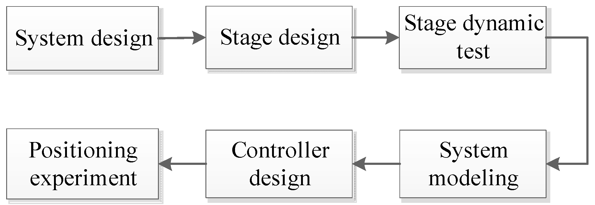
2.1. Approach
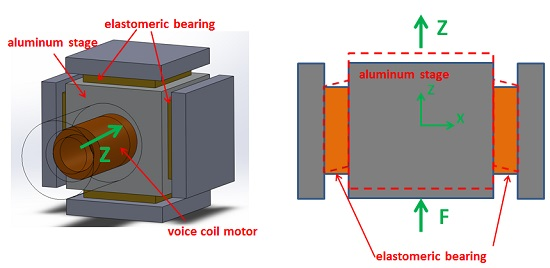
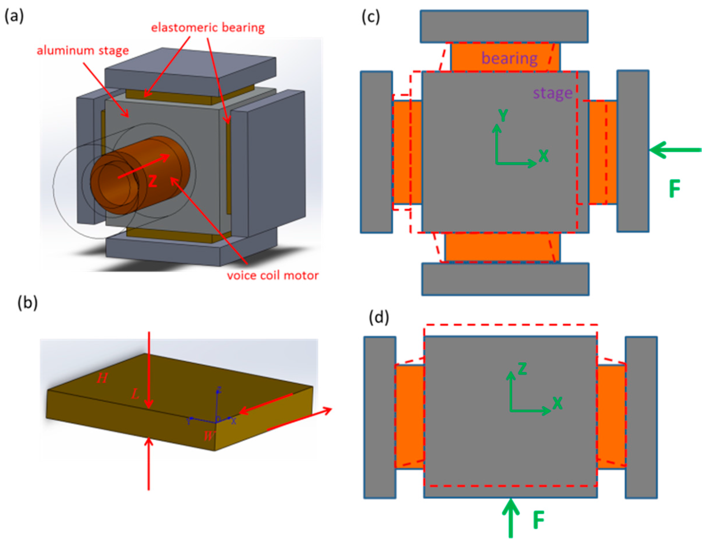
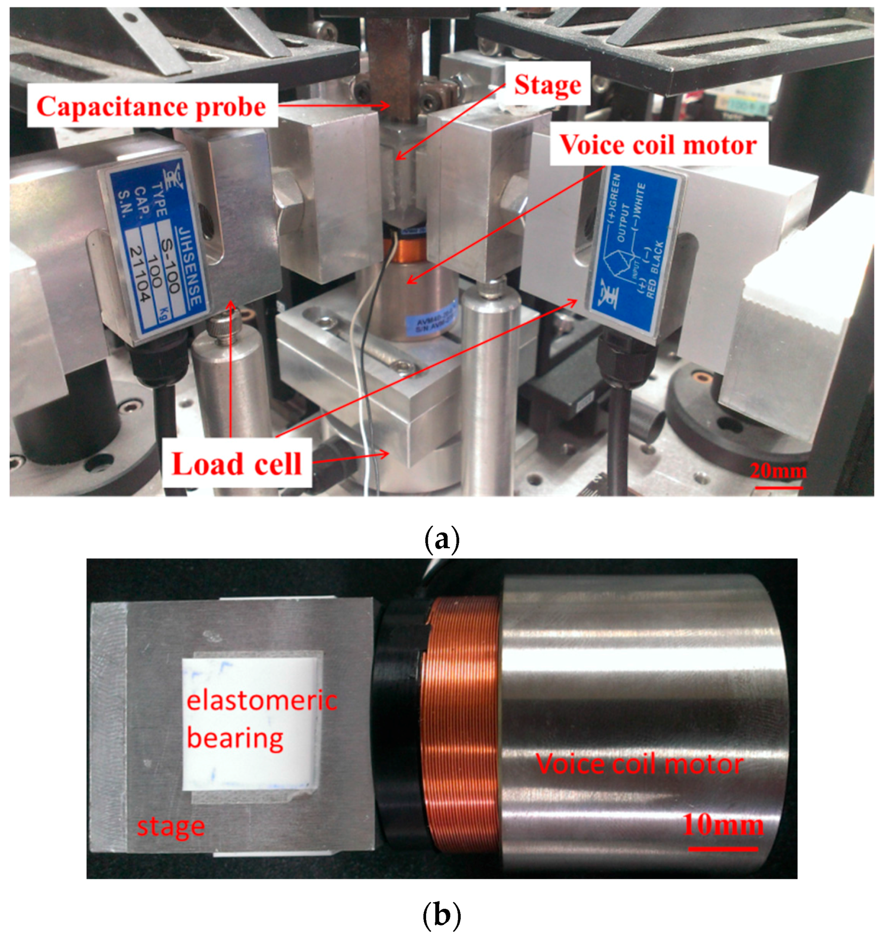
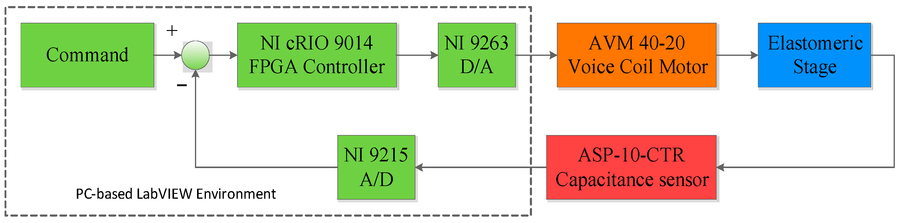
2.2. Stage Design and Realization
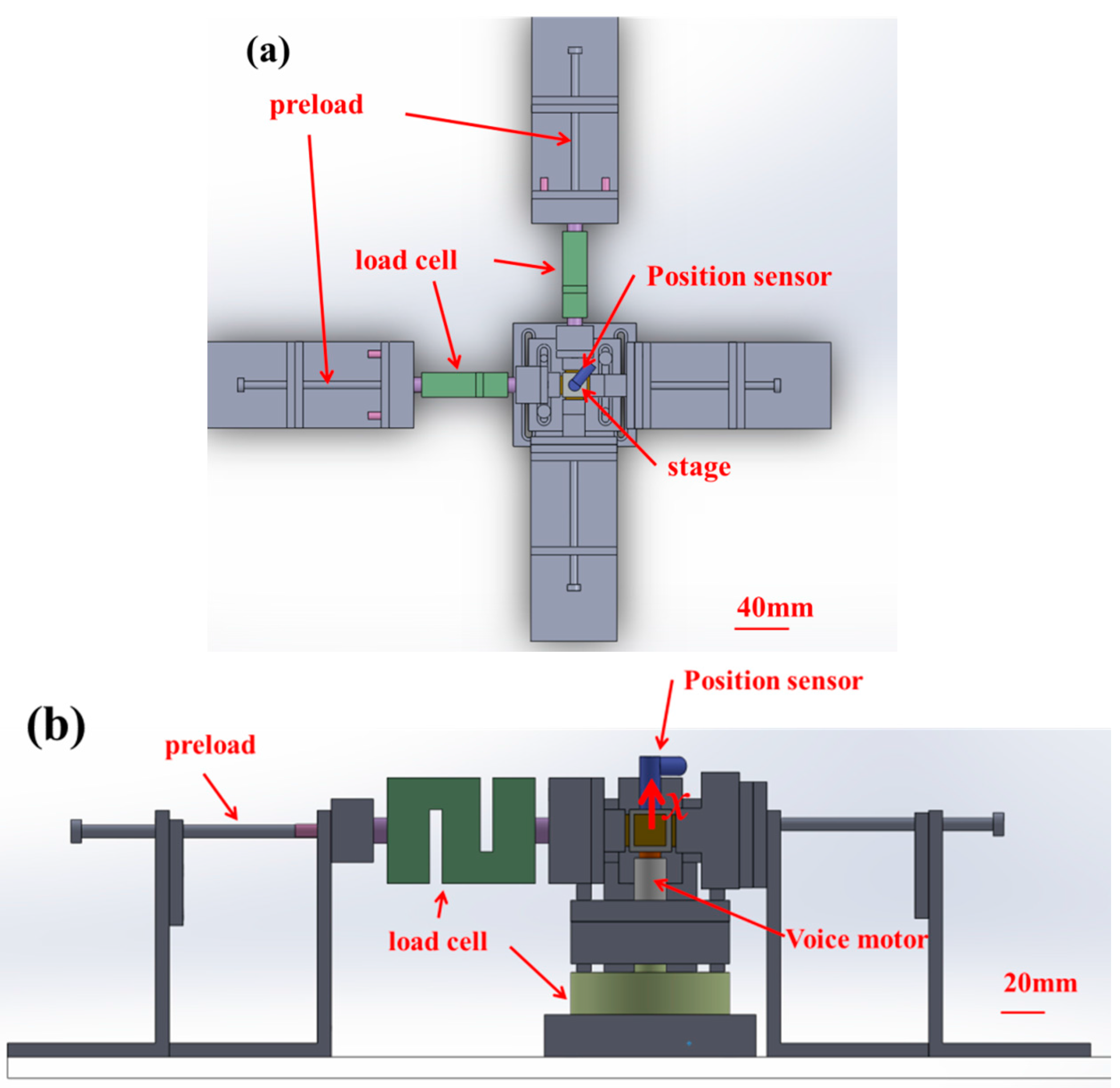
2.3. Dynamic Testing and Modeling of the Stage
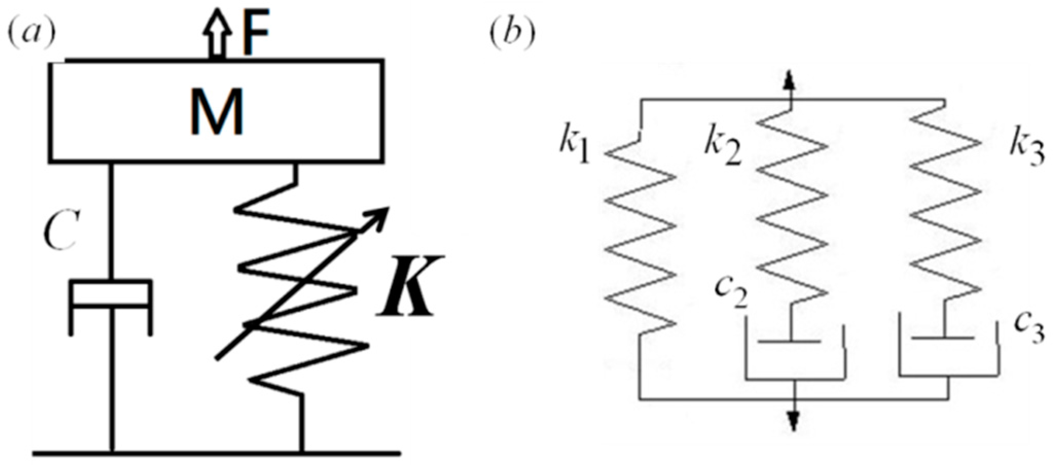
2.3.1. Stage Model
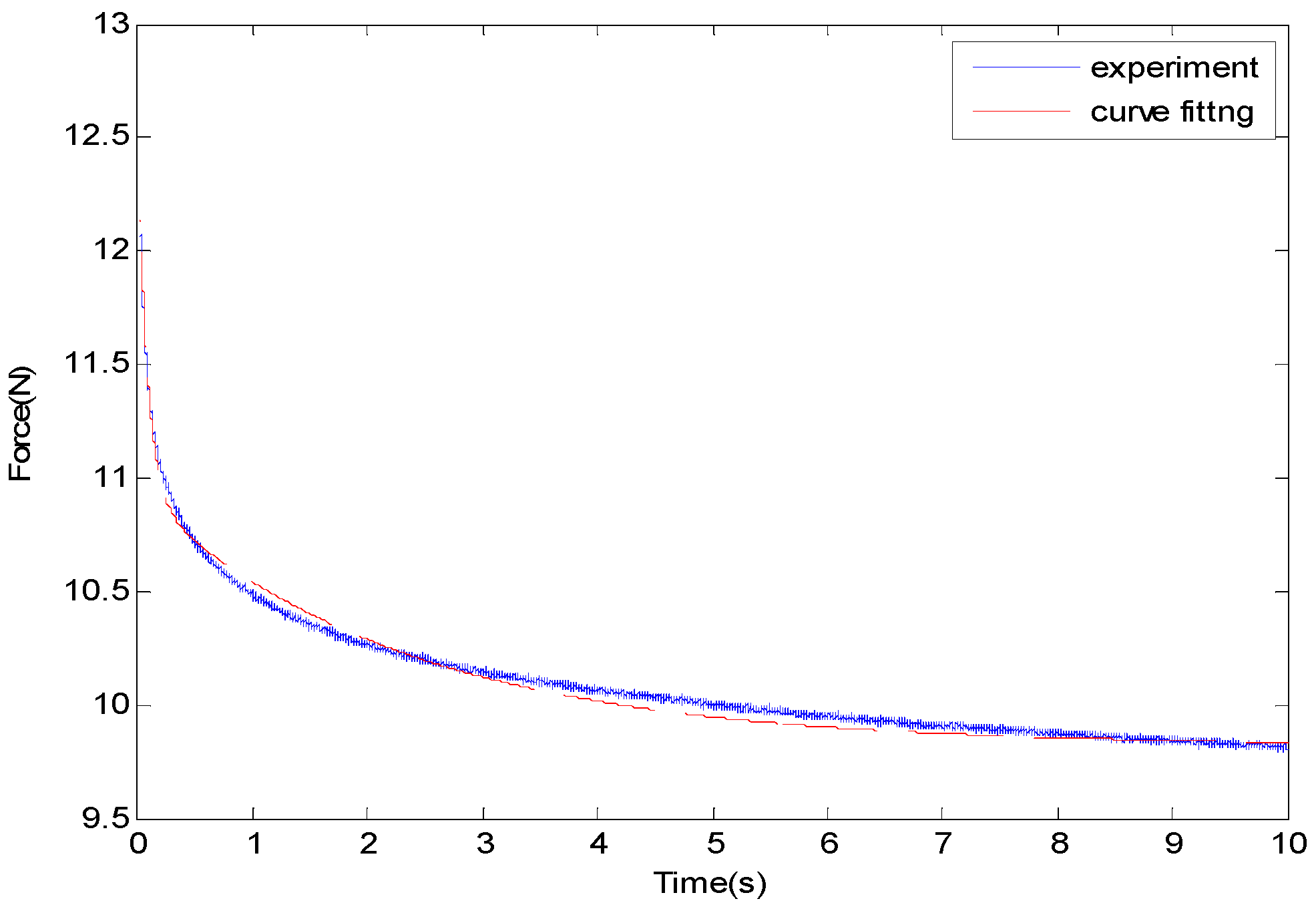
2.3.2. Stress Relaxation Experiment
2.3.3. Damping Coefficient Experiment
2.4. Controller Design
2.4.1. Proportional–Integral–Derivative (PID) Controller
2.4.2. Integral Sliding Mode Controller
3. Results
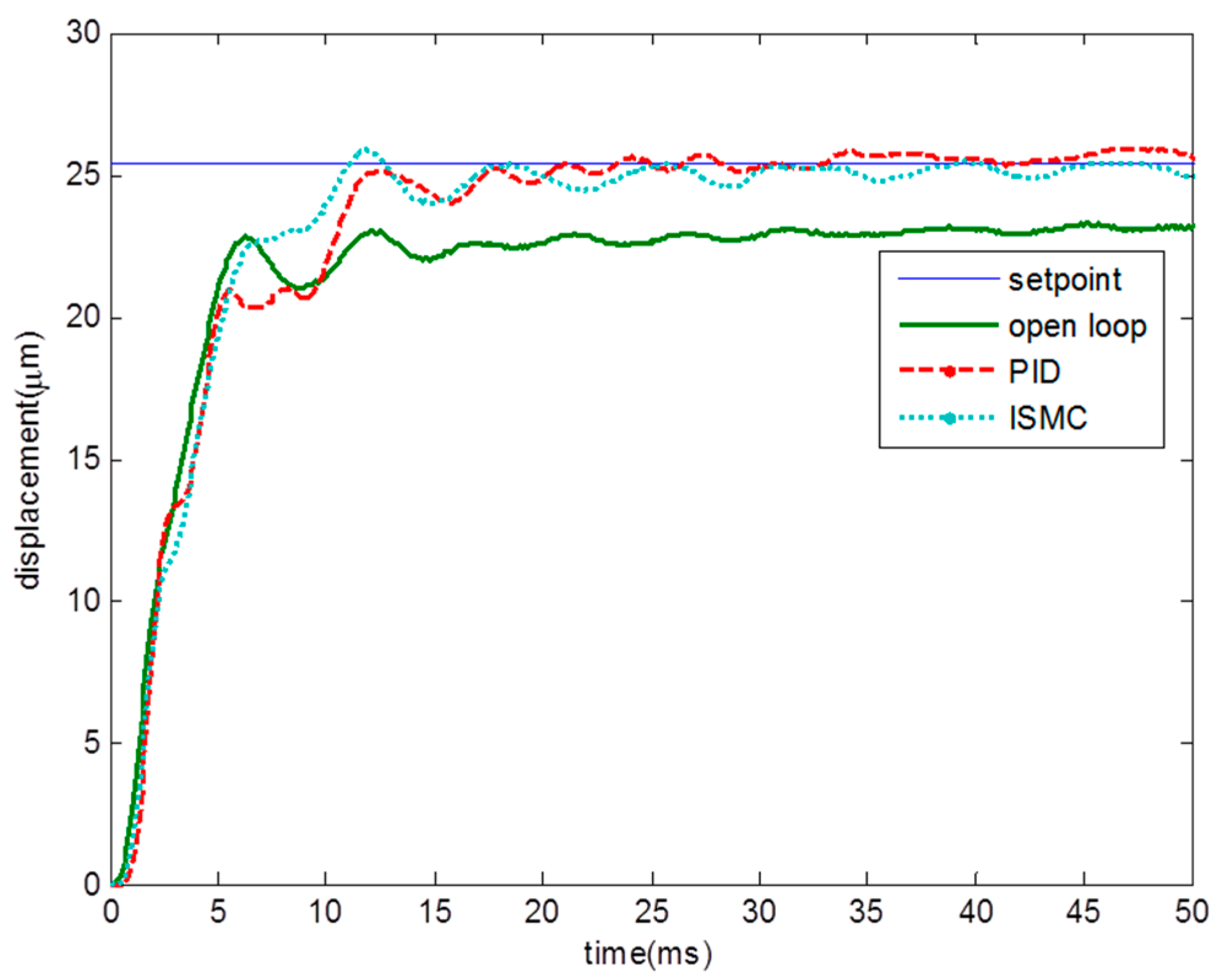
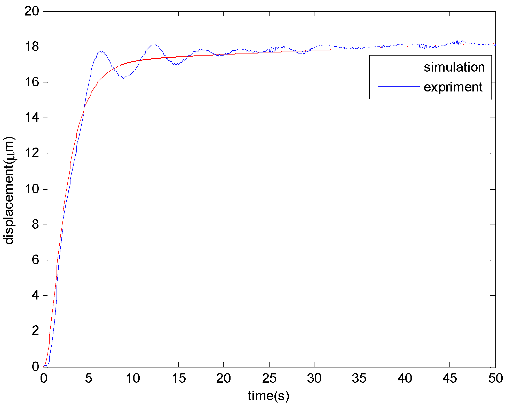
3.1. Step Response
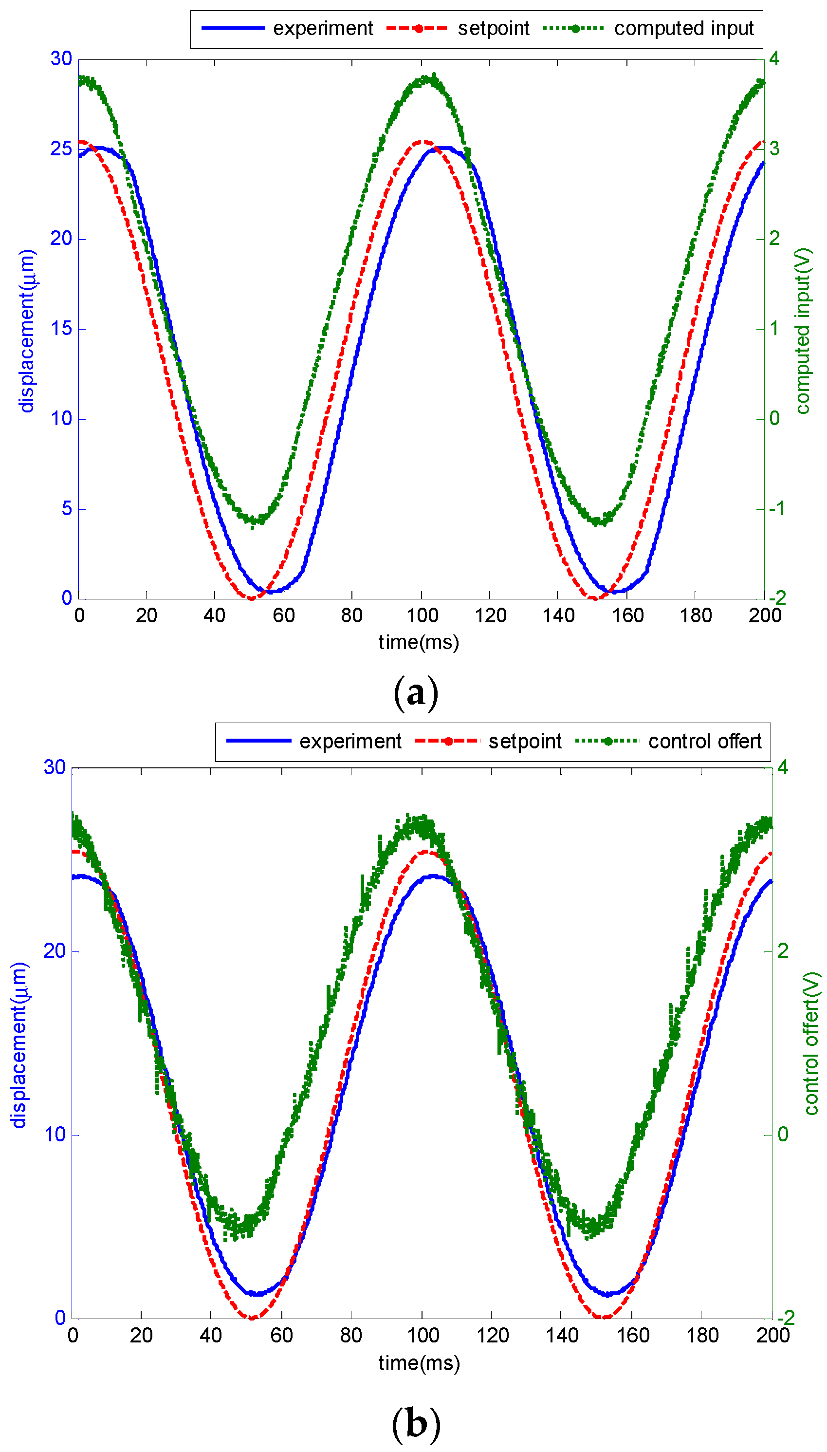
3.2. Sinusoidal Motion Tracking
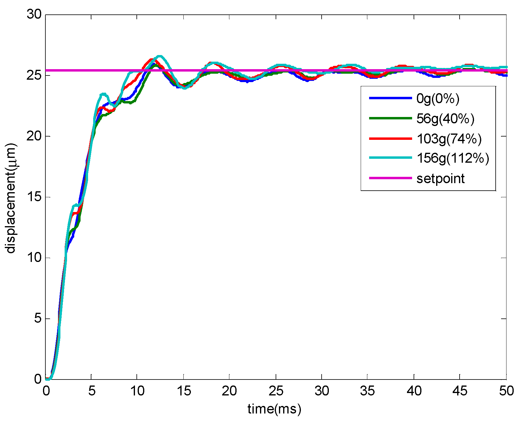
3.3. Robustness Test
4. Discussion
5. Conclusions
Acknowledgments
Author Contributions
Conflicts of Interest
References
- Woronko, A.; Huang, J.; Altintas, Y. Piezoelectric tool actuator for precision machining on conventional CNC turning centers. Precis. Eng. 2003, 27, 335–345. [Google Scholar] [CrossRef]
- Chang, C.Y.; Li, C.H.; Lin, S.Y.; Jeng, M. Application of Two Hopfield Neural Networks for Automatic Four-Element. IEEE Trans. Syst. Man Cybern. Part C Appl. Rev. 2009, 39, 352–365. [Google Scholar] [CrossRef]
- Hu, Y.; Chen, M.Z.Q.; Shu, Z.; Huang, L. Analysis and optimization for inerter-based isolators via fixed-point theory and algebraic solution. J. Sound Vib. 2015, 346, 17–36. [Google Scholar] [CrossRef] [Green Version]
- Hu, Y.; Chen, M.Z.Q.; Xu, S.Y.; Liu, Y. Semi-active inerter and its application in adaptive tuned vibration absorbers. IEEE Trans. Control Syst. Technol. 2016, in press. [Google Scholar] [CrossRef]
- Chang, S.H.; Du, B.C. A precision Piezo driven micropositioner mechanism with large travel range. Rev. Sci. Instrum. 1998, 69, 1785–1791. [Google Scholar] [CrossRef]
- Wang, W.C.; Lee, J.W.; Chen, K.S. Design and vibration control of a notch-based compliant stage for display panel inspection applications. J. Sound Vib. 2014, 333, 2701–2718. [Google Scholar] [CrossRef]
- Cuff, D.P. Electromagnetic Nanopositioner. Master’s Thesis, Massachusetts Institute of Technology, Cambridge, MA, USA, 2006. [Google Scholar]
- Kluk, D.J. An Advanced Fast Steering Mirror for Optical Communication. Master’s Thesis, Massachusetts Institute of Technology, Cambridge, MA, USA, 2002. [Google Scholar]
- Gent, A.N. Engineering with Rubber; Hanser Publications: Cincinnati, OH, USA, 2001. [Google Scholar]
- Arruda, E.M.; Boyce, M.C. A three-dimensional constitutive model for the large stretch behavior of rubber elastic materials. J. Mech. Phys. Solids 1993, 41, 389–412. [Google Scholar] [CrossRef]
- Bergström, J.S.; Boyce, M.C. Constitutive modeling of the large strain time-dependent behavior of elastomers. J. Mech. Phys. Solids 1998, 46, 931–954. [Google Scholar] [CrossRef]
- Berg, M. A non-linear rubber spring model for rail vehicle dynamics analysis. Veh. Syst. Dyn. 1998, 30, 197–212. [Google Scholar] [CrossRef]
- Boyce, M.C.; Arruda, E.M. Constitutive models of rubber elasticity: A review. Rubber Chem. Technol. 2000, 73, 504–523. [Google Scholar] [CrossRef]
- Sjöberg, M.M.; Kari, L. Non-linear behavior of a rubber isolator system using fractional derivatives. Veh. Syst. Dyn. 2002, 37, 217–236. [Google Scholar] [CrossRef]
- Cao, L.; Sadeghi, F.; Stacke, L.E. An Explicit Finite Element Model to Investigate the Effects of Elastomeric Bushing on Bearing Dynamics. J. Tribol. 2016, 138, 031104. [Google Scholar] [CrossRef]
- Claeyssen, F.; Lhermet, N.; Maillard, T. Magnetostrictive actuators compared to piezoelectric actuators. In European Workshop on Smart Structures in Engineering and Technology; International Society for Optics and Photonics: Bellingham, WA, USA, 2003; pp. 194–200. [Google Scholar]
- Flügge, W. Viscoelasticity; Springer-Verlag: New York, NY, USA, 1975. [Google Scholar]
- Ogata, K. Modern Control Engineering; Prentice Hall: Upper Saddle River, NJ, USA, 1970. [Google Scholar]
- Edwards, C.; Spurgeon, S. Sliding Mode Control: Theory and Applications; CRC Press: Boca Raton, FL, USA, 1988. [Google Scholar]
- Li, Y.; Xu, Q. Adaptive Sliding Mode Control with Perturbation Estimation and PID Sliding Surface for Motion Tracking of a Piezo-Driven Micromanipulator. IEEE Trans. Control Syst. Technol. 2010, 18, 798–810. [Google Scholar] [CrossRef]


| C (N·s/m) | k1 (N/m) | k2 (N/m) | k3 (N/m) | c2 (N·s/m) | c3 (N·s/m) |
|---|---|---|---|---|---|
| 800 | 3.86 × 10⁵ | 6.3 × 10⁴ | 4.4 × 10⁴ | 504 | 101,200 |
| Performance | PID | ISMC |
|---|---|---|
| Steady State Error (nm) | 13 | 203 |
| Overshoot (%) | 1.9 | 2.01 |
| Rise Time (ms) | 9 | 6 |
| Settling Time (ms) | 20 | 29 |
| Bandwidth (Hz) | 27 | 350 |
© 2016 by the authors; licensee MDPI, Basel, Switzerland. This article is an open access article distributed under the terms and conditions of the Creative Commons Attribution (CC-BY) license (http://creativecommons.org/licenses/by/4.0/).
Share and Cite
Teng, Y.-C.; Chen, K.-S. Analysis, Design, and Control of a Novel Elastomeric Bearing Positioning Stage. Inventions 2016, 1, 17. https://doi.org/10.3390/inventions1030017
Teng Y-C, Chen K-S. Analysis, Design, and Control of a Novel Elastomeric Bearing Positioning Stage. Inventions. 2016; 1(3):17. https://doi.org/10.3390/inventions1030017
Chicago/Turabian StyleTeng, Yen-Chu, and Kuo-Shen Chen. 2016. "Analysis, Design, and Control of a Novel Elastomeric Bearing Positioning Stage" Inventions 1, no. 3: 17. https://doi.org/10.3390/inventions1030017