1. Introduction
The high tracking accuracy and the calorimetric features have made Time Projection Chambers (TPCs) based on liquefied noble gases an established detector type for many experiments running or planned on neutrino physics [
1,
2,
3] and direct dark matter searches [
4,
5,
6].
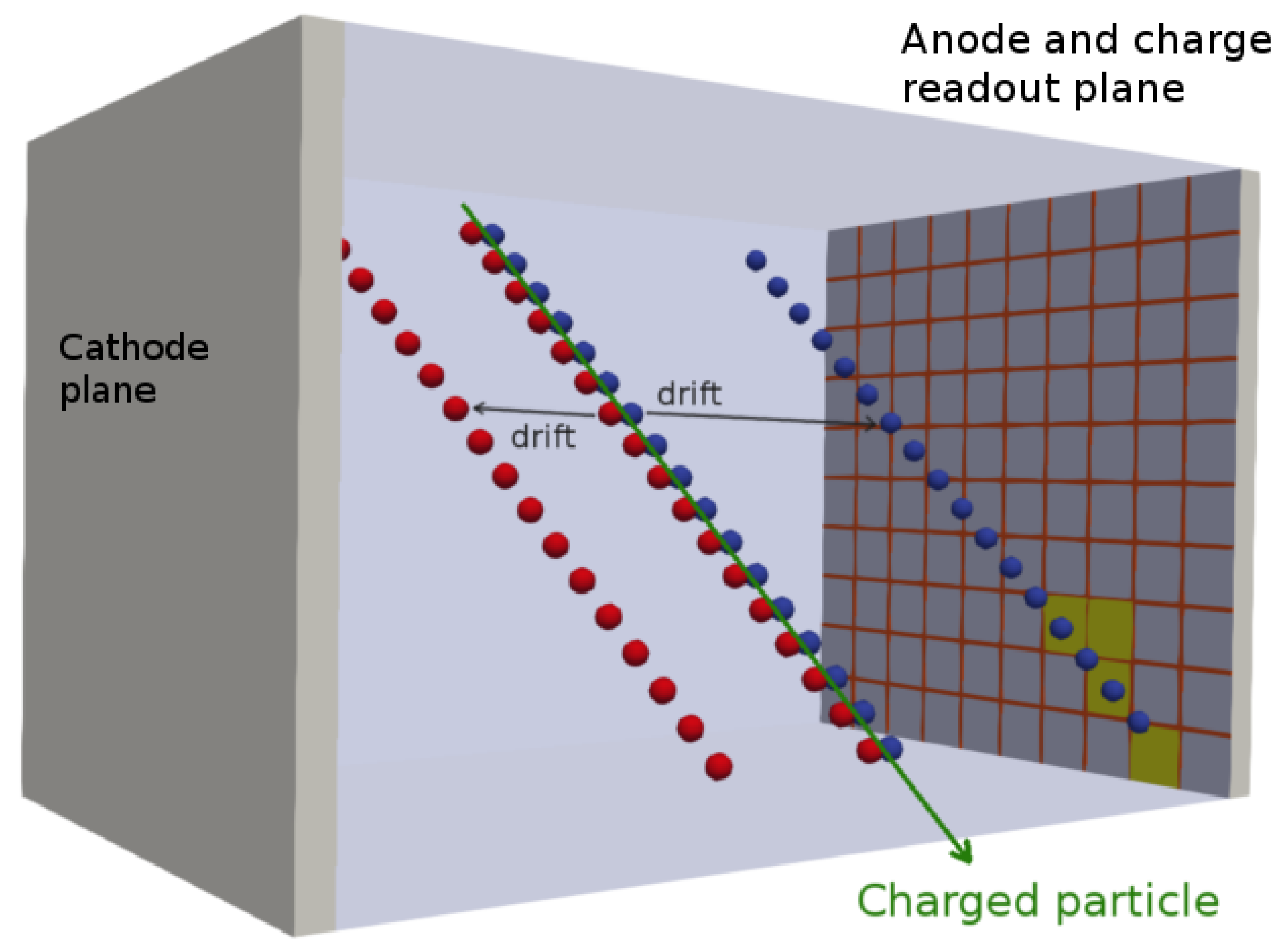
The basic working principle of a TPC is illustrated in
Figure 1: Charged particles travelling through a medium lose their energy by ionising its atoms. Due to the ionisation prompt scintillation light is produced. An electric field applied between an anode and a cathode placed in the medium (gas or liquid) forces the ionisation electrons to move (drift) towards a charge-collection device at the anode. Combining charge readout with the time signal from the scintillation light allows for a full 3D reconstruction of the events.
Conventional TPC designs [
5,
7,
8] employ metallic field cage structures to produce a uniform electric field between the anode and the cathode; these consist of a sequence of conductive elements surrounding the TPC drift region. The segments are electrically connected by resistors that produce the required voltage drop between consecutive field cage units.
The next generation of experiments will require detectors with active volume masses ranging from for neutrino-less double beta decay studies and direct dark matter searches up to for long baseline neutrino experiments, with drift lengths up to several meters.
The electrostatic energy stored in a TPC of such dimensions can be up to
[
9]. Hence, the occurrence of accidental discharges between the cathode or one of the closest field cage elements and the grounded environment around the field cage poses a serious risk of damage to the readout electronics.
The ArgonCube LAr TPC detector concept [
10] was developed among other goals to address the risks associated with high voltage (HV) [
11] and long drift distances [
12,
13] through modularisation; separating the detector volume into a number of self-contained TPCs sharing a common cryostat. Modularisation reduces the stored energy, simplifies electric-field stability and lowers the requirements for LAr purity. Additionally, it brings the benefit of a reduced track multiplicity per TPC unit which simplifies the event reconstruction. This approach requires all components of the TPC to be as compact as possible to maximise the active volume. Advancements have already been made in the charge and light readout [
14,
15,
16]; here, we present a new approach for field shaping.
We propose as an alternative to the conventional field cage, a continuous resistive plane forming a so-called “resistive shell”. This will provide a continuous linear potential distribution along the drift direction, paired with a rather simple mechanical design. By eliminating the resistor chain the component count is drastically reduced and, therefore, also the number of potential points of failure. In the case of an electric breakdown a resistive shell will limit the power release. The continuous voltage drop from the anode to the cathode requires no electric-field optimisation of the passive electric components as in a conventional field cage. At a temperature of 87 , a material would usually be expected to have a uniform sheet resistance of to be suitable for use as a resistive shell at the desired field intensity of 1 . The resistive shell can be produced with solely resistive material in the form of a thick foil or as a laminate with a resistive layer on a dielectric substrate.
The TPC presented here represents a proof of principle. The experimental setup of the prototype TPC used for the measurements is detailed in
Section 2. The results of a data taking period of 5 days carried out in July 2018 are presented in
Section 3, followed by
Section 4 with the conclusion and outlook.
2. Setup of the Prototype TPC
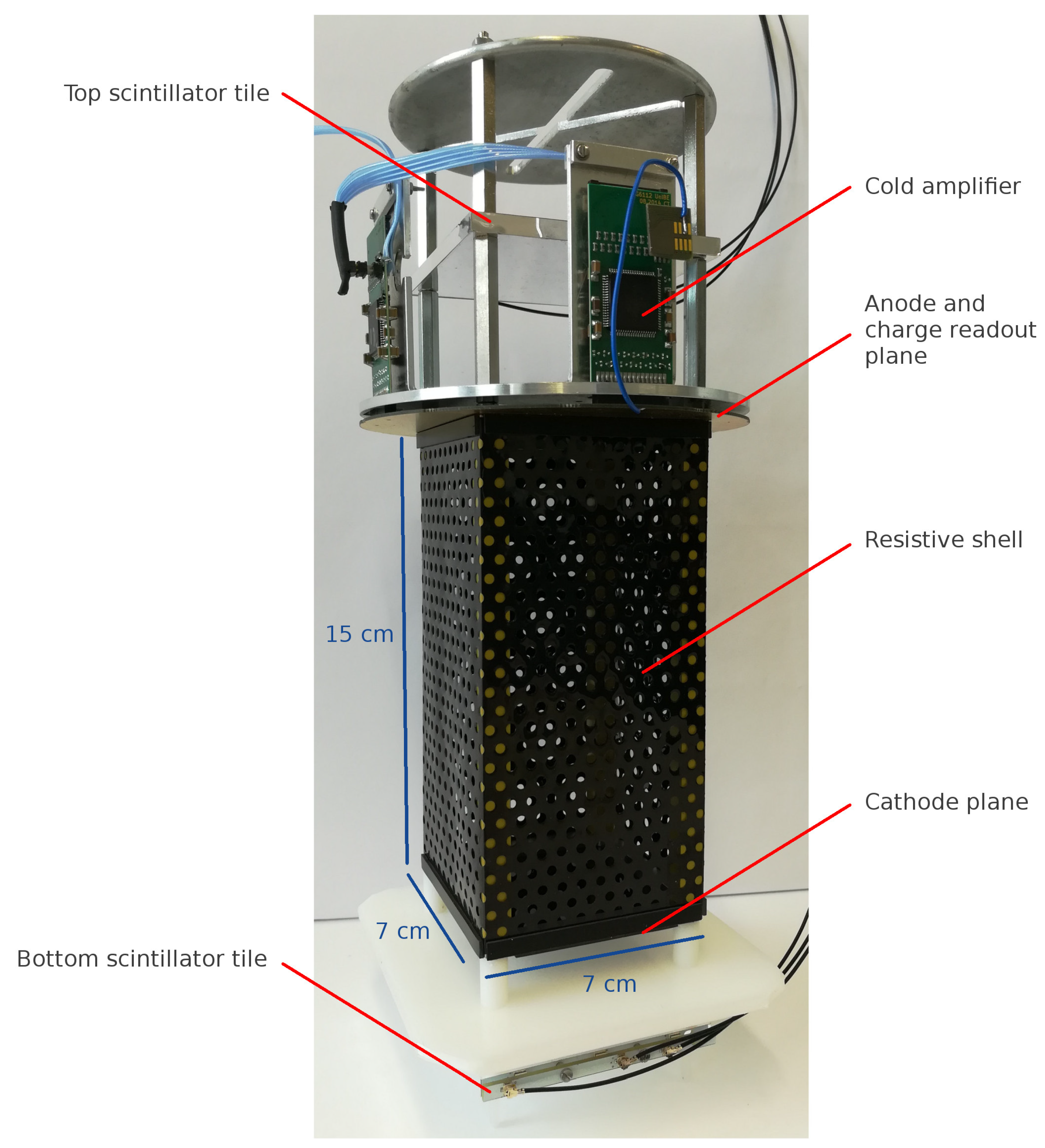
The resistive shell TPC prototype built at LHEP (Laboratory for High Energy Physics), University of Bern, is shown in
Figure 2. The TPC has a
footprint and a 15
drift length with the resistive shell constructed from a single sheet of
50
thick carbon-loaded Kapton (DuPont™, Kapton® polyimide film, E. I. du Pont de Nemours and Company,
www.dupont.com) foil. The cathode plane is made of the same material. The shell as well as the cathode were manufactured in the US before their deployment in Bern. In this application the resistive shell was perforated to allow for an adequate circulation of purified LAr in the TPC volume.
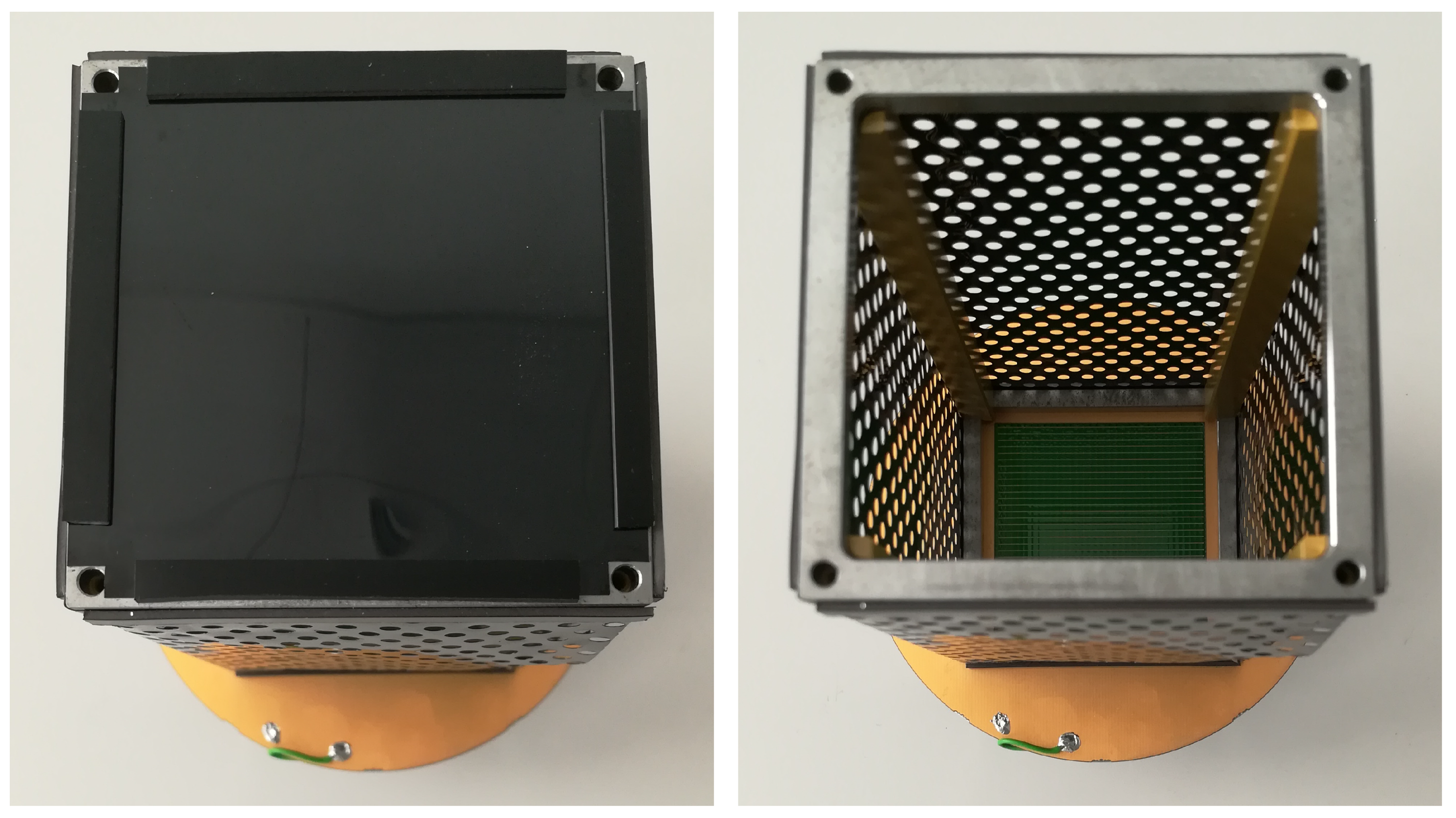
The structure of the TPC is provided by a frame as shown in
Figure 3. The frame consists of mild steel squares at both the anode and the cathode with the squares separated by four sections of Polyamide-imide that run through the length of the TPC. The resistive shell is attached with permanent magnet stripes (Halbach arrays) to a top and a bottom steel square which provide the electrical connection of the shell to the anode and the cathode. Since the electric field intensity is much larger than the field intensity produced by the magnetic stripes it is estimated that the effect of the magnets to the drifting electrons is negligible. Incorporating a conducting steel frame reduces the actual length of the resistive shell to
. Dividing this length by the shell’s 28
periphery gives a square of
sq.
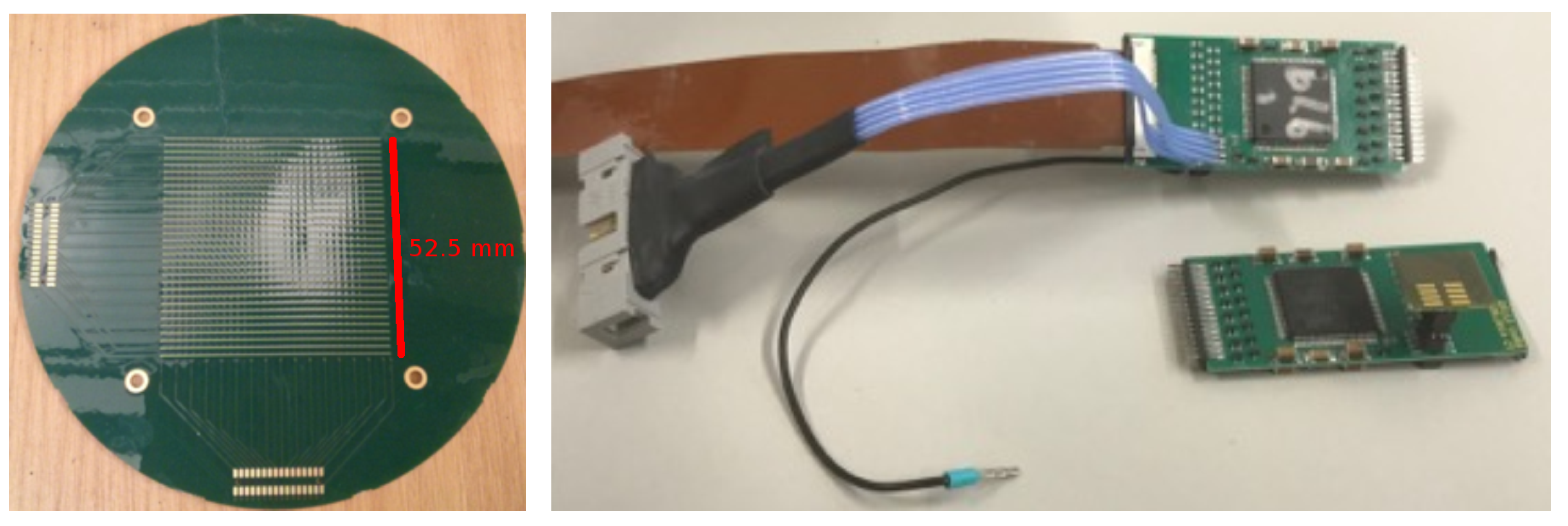
The TPC charge-readout system consists of two planes of conducting strips printed as parallel lines on either side of a 50
thick Kapton foil, as shown in
Figure 4. Each of those planes, collection and induction, are oriented at 90
and count 32 paths with a pitch of
mm. Both planes are coupled to four cryogenic preamplifiers in total: one LARASIC4* [
17] and three LARASIC7 each providing the amplification for 16 channels. The data acquisition (DAQ) was altered from that described in Ref. [
18] in order to include differential signalling. Ground loops are avoided by not connecting the signal sink to the same ground as the signal source.
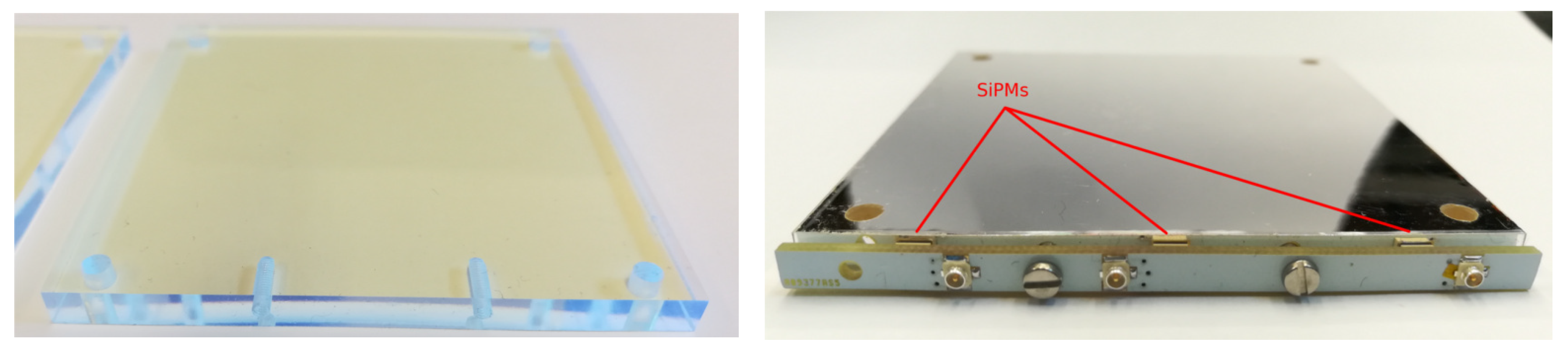
A system of two scintillator tiles with dimensions
, shown in
Figure 5, mounted above and below the TPC provides the trigger for the charge readout. Each tile is wrapped with a dielectric specular reflecting foil (VM2000, former name for Vikuiti ESR, 3M Inc). The reflector foil has a reflectance of 98 [] to the visible light spectrum [
19]. At one edge of the scintillator tile, three Hamamatsu S13360-3050VE (
http://www.hamamatsu.com/us/en/product/category/3100/4004/4113/S13360-3050PE/index.html) Silicon Photo-Multipliers (SiPMs) are used to detect the scintillation light produced by crossing cosmic muons. The construction is based on that of the ArCLight light-readout system [
16].
In order to perform the experiment, the same cryostat and HV feed-through system as in Ref. [
11] were used, where a concentration of about 1 ppm of oxygen-equivalent was achieved by continuous recirculation of LAr through purification filters. The HV power-supply (Spellmann, SL130PN150,
https://www.spellmanhv.com) readout-uncertainty is limited to
.
3. Experimental Results
The resistive shell TPC was continuously operated for 80 h at electric field intensities up to
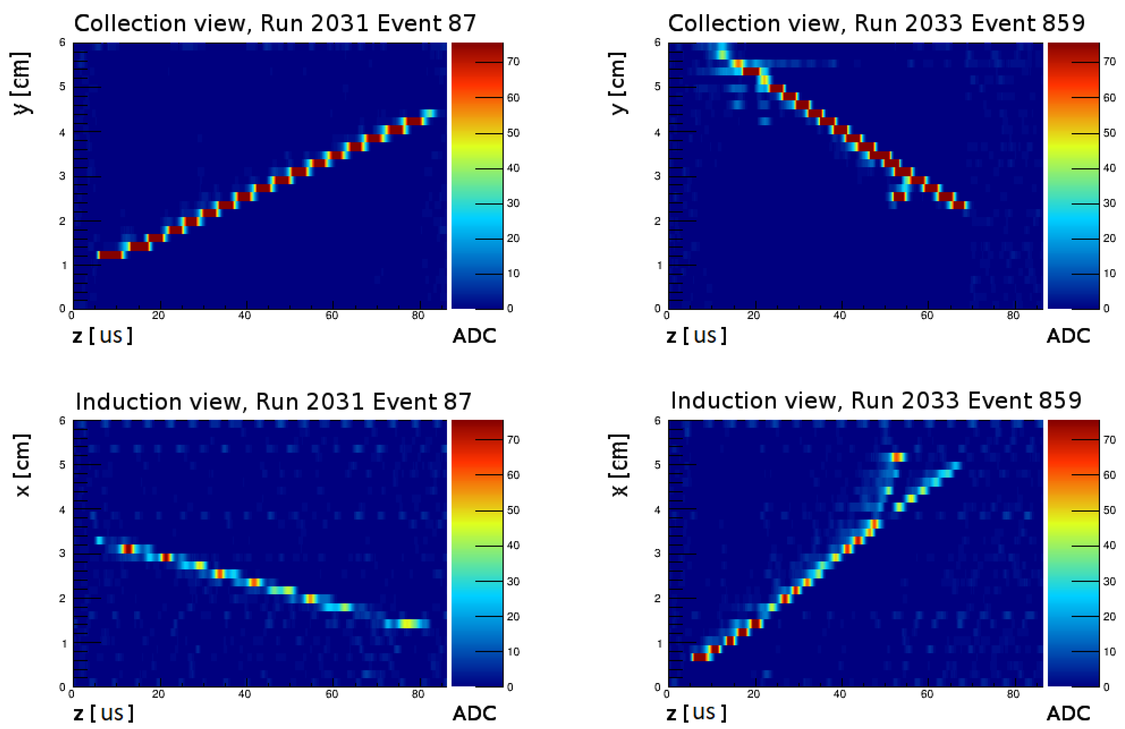
. Visual inspections showed that no local LAr boiling occurred due to power dissipation across the resistive shell. The charge-readout acquisition-trigger is based on a two-fold coincidence between the signals coming from the top and bottom scintillator tiles. This setup was chosen in order to acquire events originating from cosmic muons crossing the entire TPC drift length. Particle tracks like those shown in
Figure 6 were observed across a range of various electric field intensities.
The electric properties of the resistive foil were measured prior to the TPC construction. In particular, the sheet resistance of a sample with dimensions of was measured by applying a 100 bias voltage at both room temperature and in liquid nitrogen (LN2). In LN2 a value of 16 sq was measured, significantly higher than the value of 350 sq obtained at room temperature. This indicates a temperature dependence of the shell’s sheet resistance.
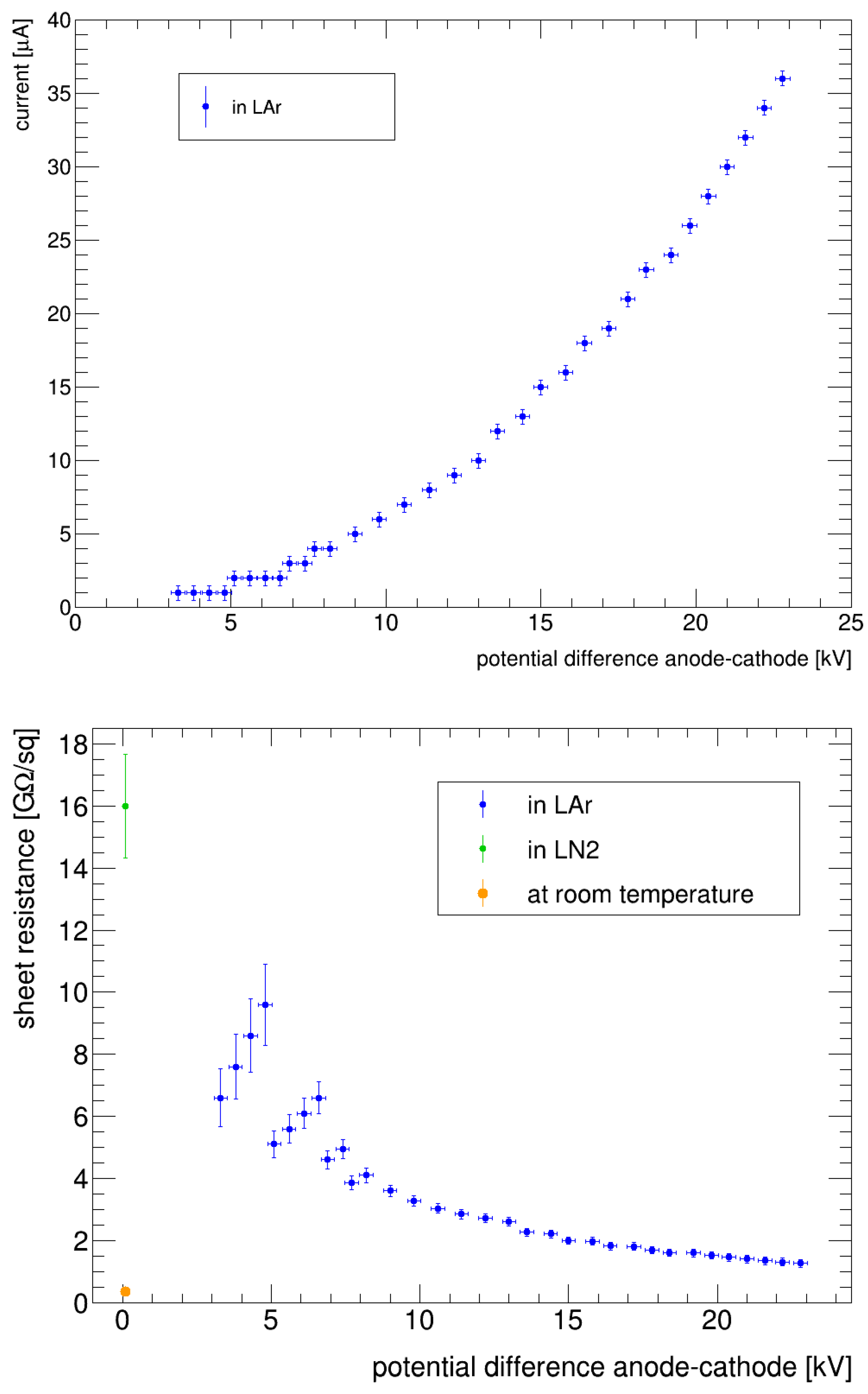
The relevant electrical properties of the resistive shell, e.g., its sheet resistance and power dissipation, can be determined by measuring the current drawn as a function of the cathode bias voltage. For this purpose, the power supply was operated up to 30
bias voltage while logging the current shown on the device.
Figure 7 shows the measured currents as well as the derived values for the shell’s sheet resistance. The power dissipated across the resistive shell for a field intensity of 1
was calculated to be
under the assumption of no local boiling. At the maximum applied cathode bias voltage the corresponding value for the power dissipation was calculated to be
. The sheet resistance of the resistive shell was found to be
sq
for a field value of 1
, as shown in
Figure 7.
Due to the limited resolution of the current drawn at the HV power supply, the measured sheet resistance has relatively large uncertainties for cathode bias voltages around 5 where the measured current was small. Furthermore, to avoid singularities, values for the sheet resistance at cathode bias voltages below 3 have been excluded since the corresponding values of the current vanished. Measuring the current with a higher accuracy would allow for a much more precise characterisation of the foil’s electrical properties.
The performance of the resistive shell has been assessed by using cosmic muon events generating long and straight ionisation tracks. For each event a set of charge pulses with the corresponding timing information was obtained from the waveforms acquired with all 64 readout strips. A collection of hits (3D space points) defined as the couples of unambiguous time coincident pulses from an induction (
x coordinate) and a collection (
y coordinate) strip was reconstructed for each event. Events with delta electron candidates and/or more than one track were rejected resulting in a final selection sample of 280 muon track events with an average of
hits per track and a most probable track length of 130 mm. Since the track lengths are comparable to the liquid argon radiation length of 140 mm the expected hits’ transverse spread due to Multiple Coulomb Scattering described in Ref. [
20] is of
and thus was neglected. For this calculation we assumed a muon energy of 4
as taken from Ref. [
20].
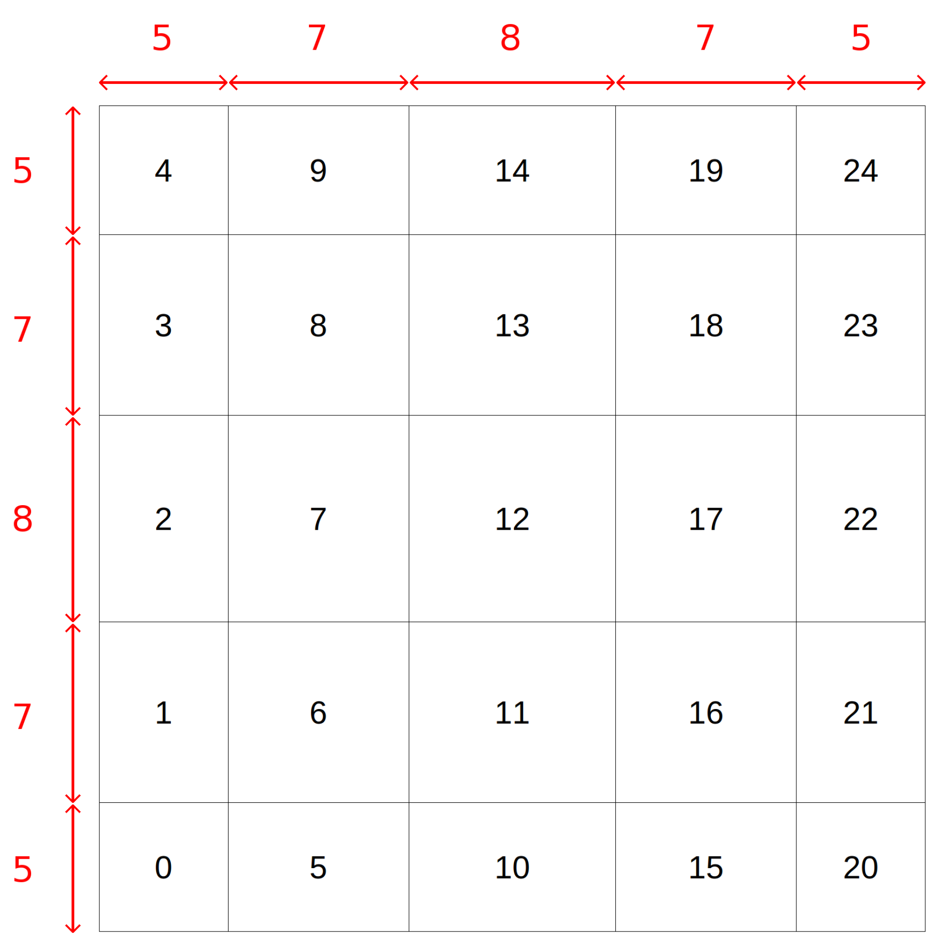
Following the event selection the parameters of a straight line corresponding to the muon candidate track were determined by using the Principal Components Analysis (PCA) applied on the set of one event’s hits. As possible electric-field non-uniformities would induce observed muon tracks with discrepancies from straight lines the hits’ deviations from the obtained principal components were studied as a function of their reconstructed position. For this study the active TPC volume was partitioned in 25 cubic regions (cuboids between the anode and the cathode), as shown in
Figure 8.
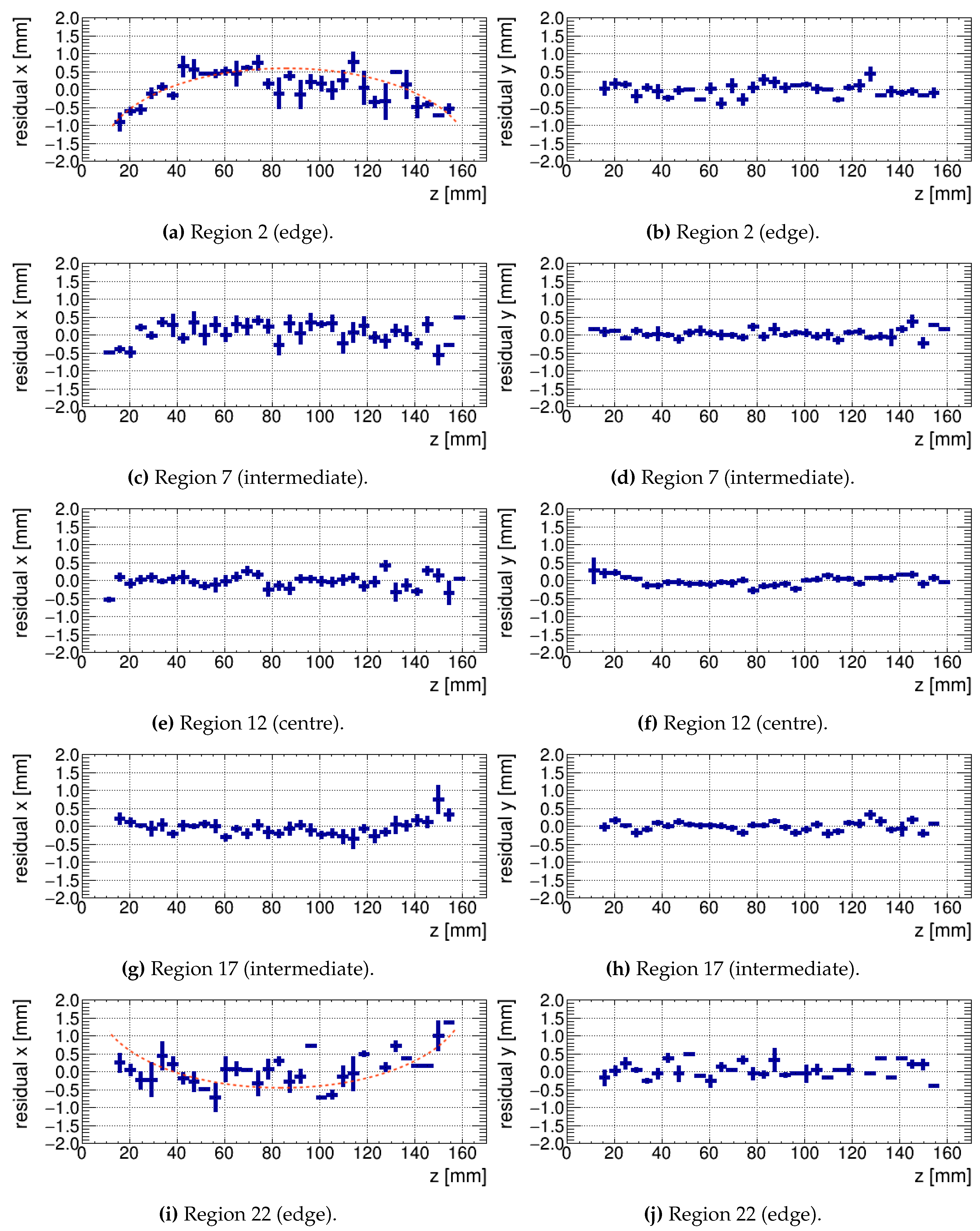
The distributions of the three coordinates of the shortest vector (residual) from the hits to the principal component were obtained for each region as functions of the
z-axis, corresponding to the drift direction. Those distributions for the 8 most central collection and induction strips are shown in
Figure 9 and
Figure 10, respectively, as profile plots showing the mean
x and
y components of the residuals for all 280 selected events. Those Figures only show the statistical uncertainties.
The
x and
y coordinates of the residuals appear to be distributed around zero with almost no dependence from the
z coordinate which signalises that the hits are distributed along a rather straight line. However, the slightly bent profile plots for the residual’s
x component in the edge regions 2 and 22 (
Figure 9) indicate some electric-field distortions in
x direction near the anode (
mm) and the cathode (
mm). Despite the small statistics of hits in the peripheral regions of the TPC, where a lower field uniformity is expected, the
x component of the residuals tend to have opposite signs for region 2 and region 22. Since for the same two regions the bespoken effect is not apparent in the profile plot of the residual’s
y component the distortion of the electric field must be rather uniform in
y direction.
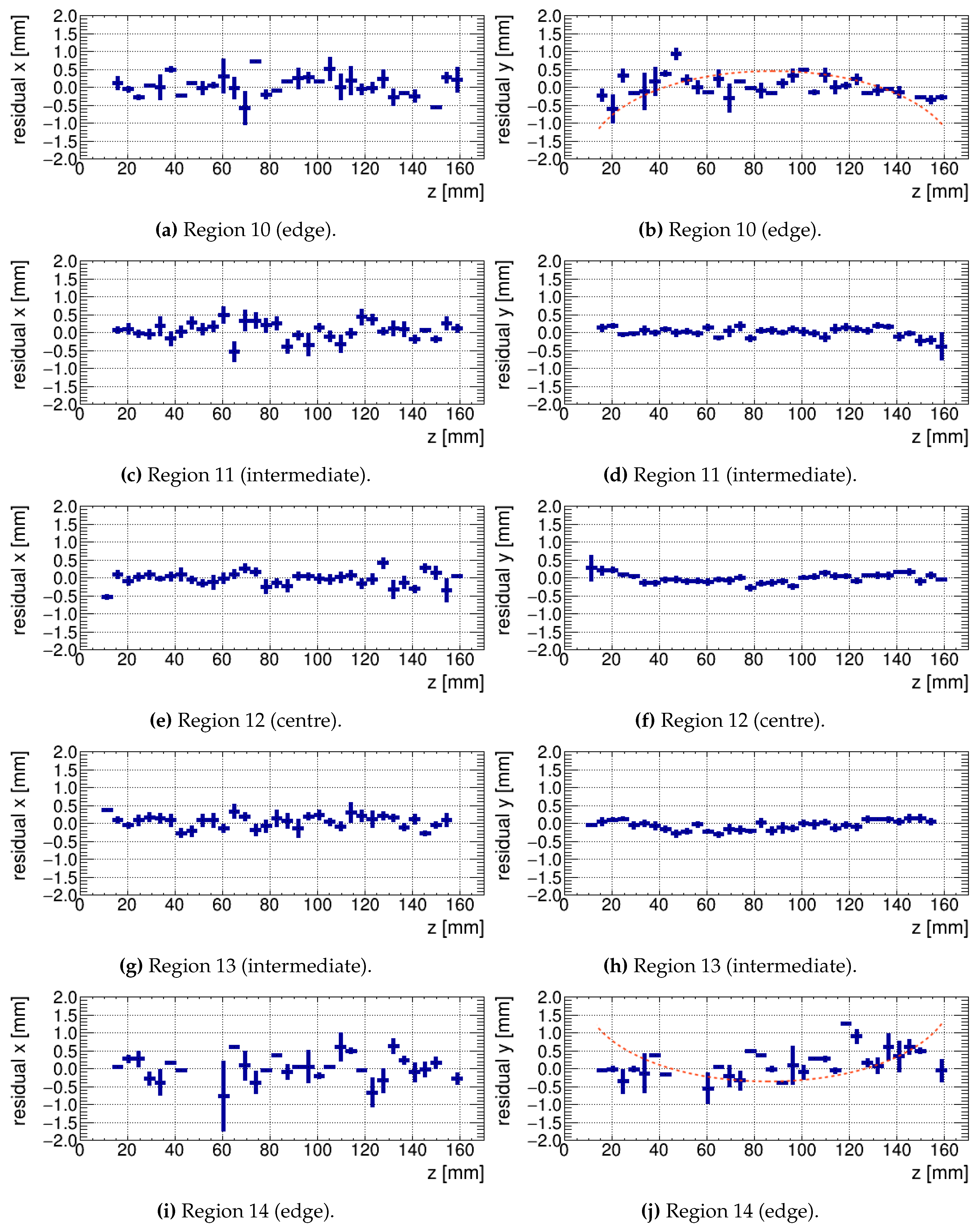
A similar but less pronounced behaviour is observed for the regions 7 and 17 (
Figure 10) where the profile plots of the
y component of the residuals appear to be slightly bent for hits close to the electrodes. This bending hints for small electric field distortions in
y direction. In analogy to the observations made before, the residual’s
x component for region 7 and 17 do not deviate significantly from zero, indicating vanishing field distortions in the
x direction.
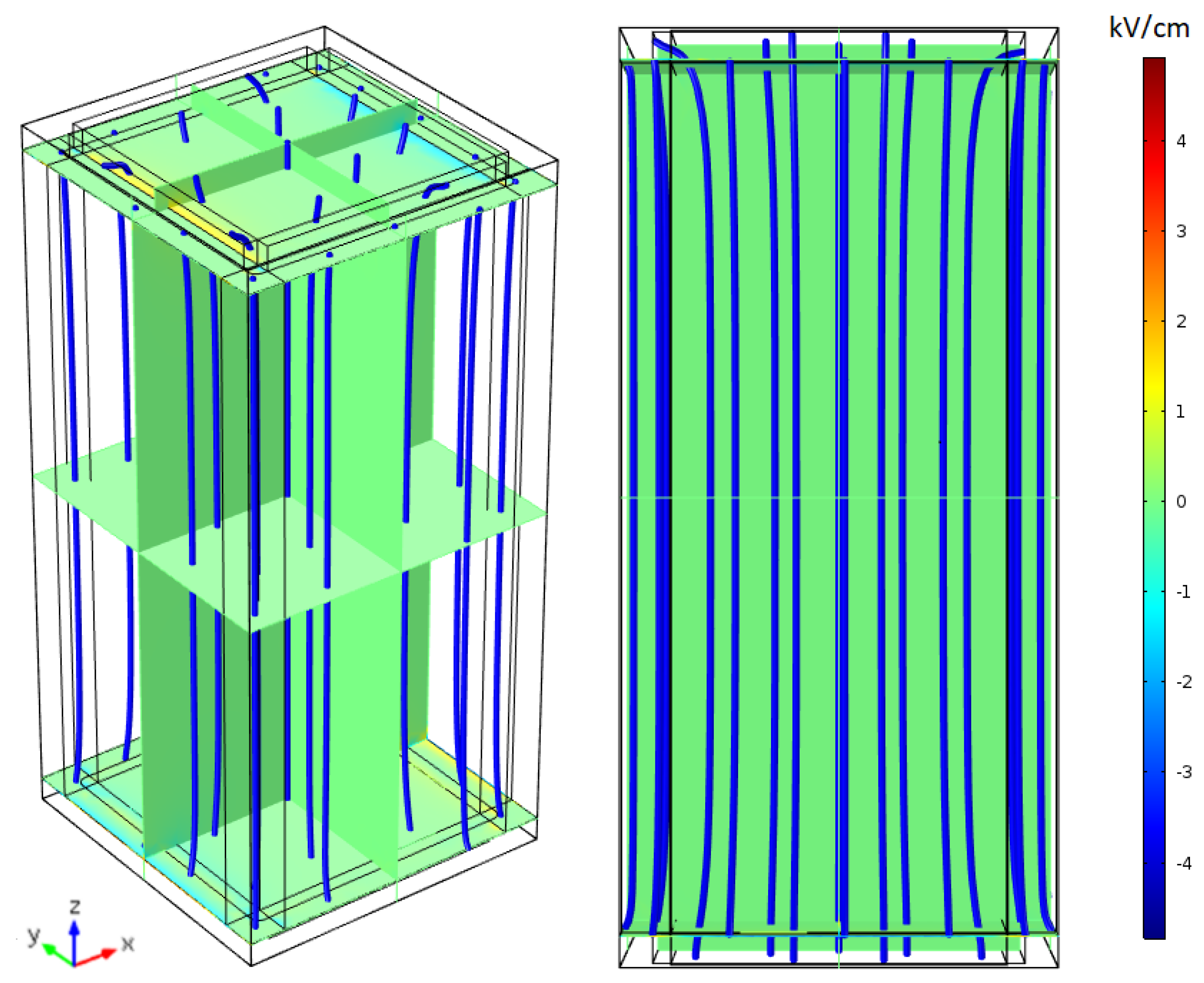
The observation that some hits near the anode or the cathode plane have larger deviations from the principal component than hits far from the electrodes motivated us to simulate the electric field within the drift volume of the TPC. For this purpose the COMSOL Multiphysics (
https://www.comsol.com) code version 5.2 was used. As a result, the electric-field lines as well as its
x components within the TPC drift volume are shown in
Figure 11. It appears that the magnitude of the electric field is a few percent higher at the edge of the drift volume than in the middle. The field lines therefore are bent towards the centre of the TPC’s active volume. Furthermore, the field’s
x and
y components are largest near the anode and the cathode and rapidly vanish at larger distances from the electrodes. The maximum electric-field distortions in
x (similar for the
y direction) are about
at the very top and bottom of the drift volume.
When simulating the TPC without any iron frame the electric-field lines are no longer bent but describe straight lines between the anode and the cathode. Hence, the observed distortions can likely be ascribed to the two iron frames and not to some features of the resistive shell.
As the ionisation electrons drift along the electric field lines, electrons produced at the edges of the TPC drift volume tend to move more outwards and are expected to have larger deviations from the principal component than electrons produced at the centre of the TPC. In addition, electrons that start to drift from regions closer to the electrodes will be reconstructed with smaller
x-
y deviation than those starting from the middle of the TPC. This is qualitatively consistent with the bent profile plots of the
x and
y components of the residuals observed in the most peripheral regions 2, 22, 10 and 14 (
Figure 9 and
Figure 10). However, for a deeper quantitative comparison between the predictions from simulations and the observed deviations a higher statistics of hits in the outer regions of the active volume, where these effects are stronger, would be needed.
4. Conclusions
A prototype liquid argon TPC instrumented with the novel approach of the resistive shell for field shaping was built and tested at LHEP, University of Bern. The shell consists of a highly resistive,
, carbon-loaded Kapton foil with a thickness of 50
. The measured electrical properties and performance of the TPC prototype showed that this innovative design is suitable for applications that require low-power consumption, minimisation of the TPC material for field shaping and maximisation of the active TPC volume. Furthermore, the high resistivity of the shell and the reduced number of components reduces the power release as well as the potential number of failure points during operating the TPC at high bias voltages. Detailed studies for the characterisation of the resistive foil’s power dissipation in the case of an electric breakdown are still missing and will be object of future experimental works employing similar modalities as in Ref. [
11]. Finally, compared to a conventional field cage with a resistor chain the resistive shell with its larger surface minimizes the heat load per unit area and thus reduces local boiling of the noble liquid.
During a measurement campaign of about 4 days in July 2018, straight ionisation tracks induced by cosmic muons were detected. Since the prototype TPC is rather small, with a drift-field volume of only
, the characterisation of the electric-field uniformity obtained with the experiment is limited. Further limitations come from the small sample of only 280 analysed muon candidate tracks. However, the analysis discussed in
Section 3 shows mean deviations from the hits to the track’s principal component of less than 1
, which are largest in regions close to the edges of the TPC and near the anode or the cathode plane. This can be qualitatively explained with the COMSOL simulated electric-field distortions introduced by two iron frames connecting the anode and the cathode with the resistive shell. According to simulations the electric-field distortions vanish when removing the frames showing that this effect does not depend on any specific features of the adopted technique.
In order to further characterise the capabilities of the resistive shell to shape electric fields in TPCs a larger device without iron frames and able to collect larger samples of straight muon tracks will be required. Another possibility to characterise the electric-field distortions would be the use of a steerable UV laser, such as presented in Refs. [
21,
22].
We observed that the sheet resistance of the shell depends in a non-linear way on the applied bias voltage. Since this behaviour would affect the heat load and thus the diffusion of the noble liquid when the applied voltage is changed, future experiments should test and quantify the long term stability of the foil’s electric properties when a constant bias voltage is applied to it.
The tested TPC design can be easily scaled to several square meters of surface area of the shell as needed by the next generation of detectors for neutrino physics as well as for neutrino-less double beta decay experiments and direct dark matter searches. For this purpose we will adopt this novel TPC technology for the upcoming ArgonCube 2x2 Demonstrator as well as for the possible development of one of the far-detector modules of the DUNE experiment.

 ,
, 


