Proton Radiography by Multiple Coulomb Scattering with Nuclear Emulsion Detectors


1
Albert Einstein Center for Fundamental Physics, Laboratory for High Energy Physics, University of Bern, 3012 Bern, Switzerland
2
Department of Physics “Ettore Pancini”, University of Napoli Federico II, Complesso Universitario di Monte S. Angelo, 80126 Napoli, Italy
*
Author to whom correspondence should be addressed.
†
Current address: Department of Physics, University of Rome “La Sapienza”, P.le Aldo Moro 5, 00185 Roma, Italy.
Instruments 2019, 3(1), 19; https://doi.org/10.3390/instruments3010019
Submission received: 14 January 2019
/
Revised: 7 February 2019
/
Accepted: 15 February 2019
/
Published: 17 February 2019
(This article belongs to the Collection Selected Papers from Instruments’ Editorial Board Members)
Abstract
:The possibility of performing proton radiography by using the proton angular spread due to Coulomb multiple scattering was investigated, for the first time, with an emulsion film detector. Two different phantoms were irradiated with the therapeutic proton beam at the Paul Scherrer Institut (PSI) in Villigen, Switzerland. The first one is a simple polymethylmethacrylate (PMMA) block having two different thicknesses (4 cm and 3 cm), and the second one is a PMMA cube with five aluminum rods embedded along a diagonal. Only one emulsion film was needed to perform the radiography, an important issue as the analysis of this kind of detector is time-consuming. Furthermore, the method showed an enhanced contrast when high atomic-number materials are traversed. This gives an advantage, when compared to proton range radiography.
1. Introduction
Proton radiography is an imaging technique undergoing a growing development, following the widespread use of proton-therapy for cancer treatment. This modality would definitely improve with a clinical use of proton radiography, which provides direct information on the density of the tissues, enhancing the precision of treatment planning. In this framework, different proton radiography systems have been tested [1,2,3]. Our group investigated the possibility of using emulsion detectors [4] to image different phantoms of the proton therapeutic beam at the Paul Scherrer Institut (PSI) in Villigen, Switzerland. The proton radiography was successfully performed with an Emulsion Cloud Chamber (ECC), a sandwich of emulsion films interleaved with tissue-equivalent plates, that allowed for the assessment of the proton residual range [5]. The same experimental setup also allowed us to evaluate the dose distribution in the halo region of the proton clinical pencil beam [6]. In the present study, we exploit an alternative method to perform the radiography, based on the evaluation of Coulomb multiple scattering of protons while traversing different materials. This approach requires a detector with a high angular resolution, for which emulsion films represent the optimal solution. In fact, one double-layer nuclear emulsion film allows for high precision tracking of charged particles, and the angular distribution can be reconstructed with a resolution of 1 mrad [5]. With this methodology, only a single emulsion film is needed for the proton multiple scattering evaluation, with the clear advantage of a faster data scanning and analysis procedure. Furthermore, the method also features, with respect to the proton range radiography, an increased contrast when different atomic number materials are investigated. In this paper, we report on the first results of proton radiography by means of multiple Coulomb scattering with nuclear emulsions. On this basis, the contrast is compared for proton range radiography and proton scattering radiography, with the same phantoms and irradiation conditions.
2. Materials and Methods
For the detector description and irradiation of the phantom, we refer to [5]. Briefly, we imaged the two objects, shown in Figure 1: Phantom 1, a step of polymethylmethacrylate (PMMA) with density 1.20 g·cm, featuring the two thicknesses of 3 cm and 4 cm; Phantom 2 was a 4.5 cm thick PMMA block containing five rods of aluminum ( 5 × 5 mm section) equally spaced along a diagonal.
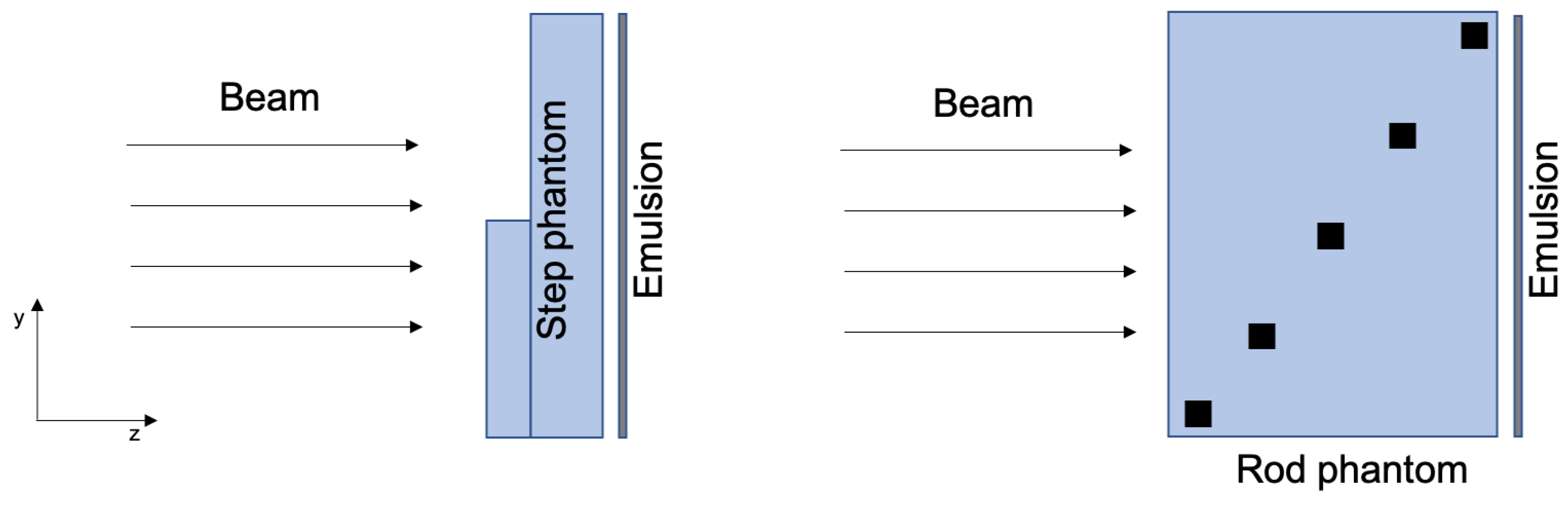
The radiography was performed using the Gantry 1 of the PSI, delivering a therapeutic proton beam with kinetic energy of 138 MeV [5,6]. The geometry of the irradiation is shown in Figure 2. In order avoid track overlapping in the emulsion, the particle flux was limited to about 100 protons/mm.
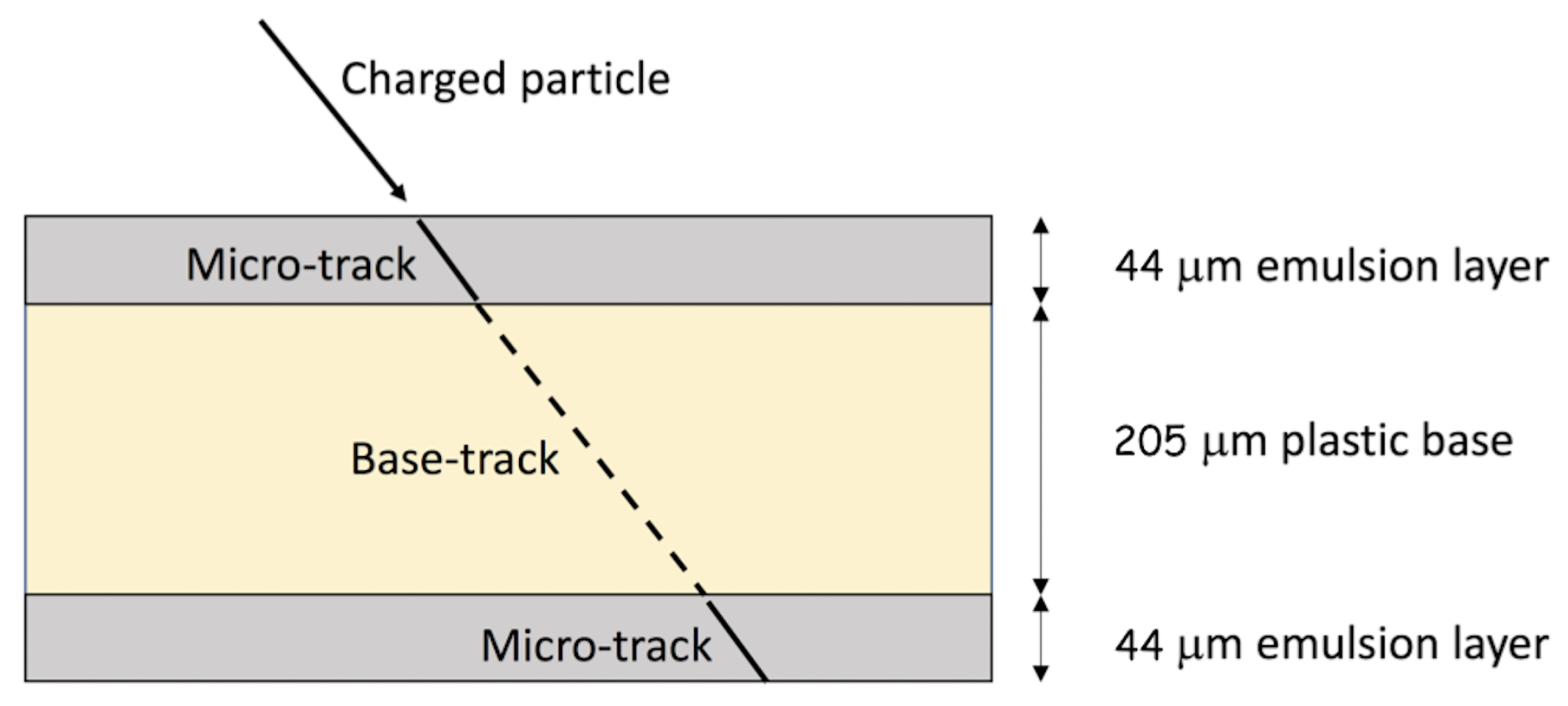
The emulsion film used for this work consists of two layers of 44 m thick sensitive gel, coated on both sides of a 205 m thick triacetate base (See Figure 3). Ionising particles produce tracks in the two sensitive layers that, once developed through a chemical process, result in a column of silver grains (micro-tracks), visible under an optical microscope. After irradiation and development, the emulsions were scanned at the Laboratory for High Energy Physics (LHEP) in Bern, using an automatic microscope [7] optimised for the reconstruction of highly ionising particles. The signals of protons were clearly visible over a negligible background, thus allowing an efficient track reconstruction.
The assessment of the scattering angle can provide useful information on the object to be imaged. The root-mean-square scattering angle projected onto any plane is given by [8]:
with for protons, and where c is the light velocity, is the ratio between the particle velocity and c, p is the particle momentum in MeV/c, x is the thickness of the traversed material, and is the radiation length of the considered material, which can be expressed by means of the approximated formula [8]:
where Z and A are the atomic number and weight, respectively. Differences due to the type of traversed materials translate into a difference in the root mean square (RMS) of the scattering angles. If x and y are the two planar dimensions on the emulsion film, the angles, with respect to the normal direction of the incident beam (z), can be given as and :
where d is the distance between the two layers, and and are the proton coordinate in the first and second emulsion layer, respectively. The scattering angle RMS can be assessed from and .
Protons crossing the phantoms were simulated by means of the software package SRIM [9], providing the directional cosines of the trajectory of the transmitted ions, starting from a perfectly collimated beam with the initial energy of 138 MeV. The unit vector of the emerging trajectory is then given by:
where , , and are the angles between the unit vector and the corresponding axis of the reference frame. and are related to the unit vectors, according to:
where z is the direction of the beam.
3. Results
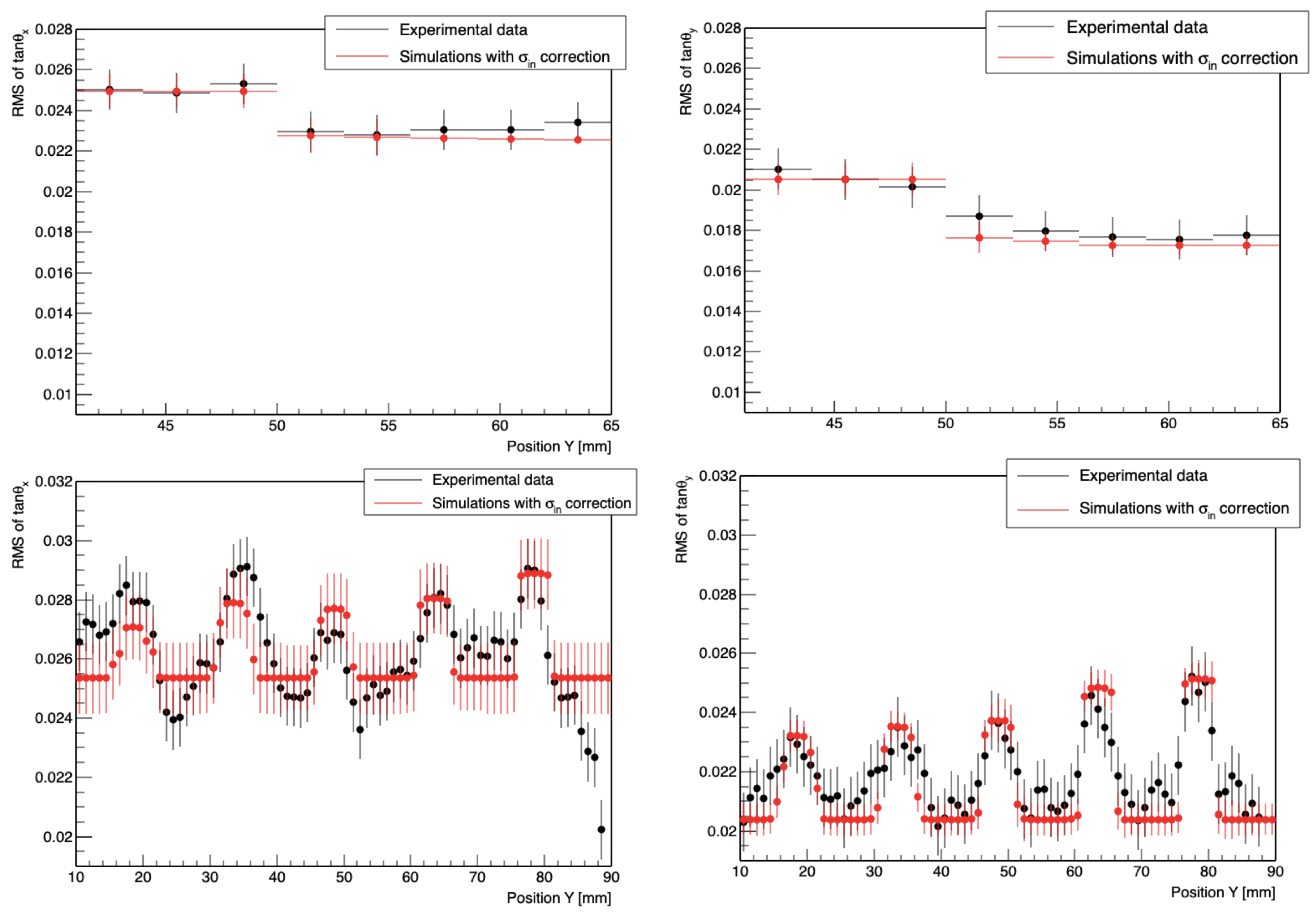
The RMS values of and are reported, in Figure 4, as a function of the y coordinate of the phantoms. The step of Phantom 1 (top) and the rods of Phantom 2 (bottom) are clearly visible. The plots in the top row of Figure 4 show that the experimental data were concentrated around two mean scattering angle values, corresponding to the two thicknesses, 4 cm and 3 cm, of Phantom 1. In the bottom row of Figure 4, the scattering profiles of Phantom 2 clearly show the presence of aluminum rods. The scattering angle, due to the rods, was found to be dependent on the rod depth inside the PMMA block. The first peak on the left corresponds to the aluminum rod closest to the incident protons. As expected, the RMS had an increasing trend, going from the first to the fifth rod, according to the inverse relationship between the Coulomb scattering and the velocity of the particle, which was slowed down in PMMA.
In the same figure, the red points represent the results of the simulation, which takes into account the proton beam spread. Indeed, the RMS angle of the initial beam () and the spread due to scattering inside the target of a given material () contributed to the RMS of (), such that:
where was evaluated by means of the simulations based on a perfectly collimated beam, and had to be determined by using the experimental data. It should be noted that was a property of the beam and equally affected all the points. was then calculated by minimising the function:
where is the experimental data uncertainty, and N the number of experimental points. The obtained values along the x and y axes were, then, added in quadrature to the simulated values.
On the basis of the angle RMS values, we can define the contrast as a parameter for the quality of the radiography. In the case of the step phantom, we can assess how well we can distinguish the boundary between the two different thicknesses. For the rod phantom, we have to assess how well we can distinguish between the aluminum rods and the PMMA block where they are inserted. We then define the contrast as:
In the case of Phantom 1, and were the RMS angle values corresponding to the two thicknesses. For Phanotm 2, the contrast was calculated in correspondence with each rod (), with respect to the PMMA block (). In Table 1, we report the contrast values experimentally obtained and those calculated by means of the simulation for the two phantoms. For comparison, the contrast values for proton range radiography with the same phantoms were calculated on the basis of our previous work [5], and shown in Table 1.
It is clear that, for Phantom 1, the contrast for the two methods was comparable; while, for Phantom 2, the contrast obtained with the method described in the present paper was about , while with the contrast with proton residual range measurements was only about . Therefore, when there is a substantial difference in the atomic number, the knowledge of mean scattering angle provides complementary information that can be valuable for clinical applications.
4. Conclusions
Proton radiography by multiple Coulomb scattering was performed, for the first time, using one double-layer emulsion film detector. The clinical proton beam of the Gantry 1, in the Centre for Proton Therapy (CPT) of the Paul Scherrer Institut (PSI) in Switzerland, was used.
Two different phantoms were imaged, one featuring a 1 cm step in PMMA and one constituted of five aluminum rods embedded into a PMMA block and located at different distances from the detector. The results obtained with this technique were compared with proton range radiography images of the same phantoms. Proton Coulomb scattering radiography was found to be characterised by a much higher contrast for materials of different atomic number—a potential advantage for clinical applications. The two techniques led to a similar contrast, when only PMMA was considered.
Proton radiography with nuclear emulsion films has the advantage of not requiring complex electronic detectors, but has the drawback of being off-line. Furthermore, the chemical development and scanning timing represent a limiting factor for clinical applications. This is mostly the case of the proton range technique, in which a large number of emulsion films are required to assess the path of the protons. On the other hand, the proton scattering technique requires only one film, representing a much faster and simpler solution. The novel imaging methodology described in this paper could be attractive for future developments in proton therapy.
Author Contributions
Conceptualization, S.B. and P.S.; methodology, S.B. and P.S.; formal analysis, G.P.; investigation, S.B.; data curation, T.S.C.; writing—original draft preparation, G.P.; writing—review and editing, S.B. and P.S.; supervision, S.B. and P.S.
Funding
This research received no external funding.
Acknowledgments
The authors would like to acknowledge the kind collaboration of the colleagues of the Center for Proton Therapy (CPT) at the Paul Scherrer Institute and contributions by our mechanical workshop at LHEP. One of the authors, T.S.C., was financially supported by the Swiss National Science Foundation (Grant CR23I2_156852).
Conflicts of Interest
The authors declare no conflict of interest.
References
- Johnson, R.P. Review of medical radiography and tomography with proton beams. Rep. Prog. Phys. 2018, 81, 016701. [Google Scholar] [CrossRef] [PubMed]
- Plautz, T.; Bashkirov, V.; Feng, V.; Hurley, F.; Johnson, R.P.; Leary, C.; Macafee, S.; Plumb, A.; Rykalin, V.; Sadrozinskim, H.F.-W.; et al. 200 MeV proton radiography studies with hand phantom using a prototype proton CT scanner. IEEE Trans. Med. Imaging 2014, 33, 875. [Google Scholar] [CrossRef] [PubMed]
- Taylor, J.T.; Poludniowski, G.; Price, T.; Waltham, C.; Allport, P.P.; Casse, G.L.; Esposito, M.; Evans, P.M.; Green, S.; Manger, S.; et al. An experimental demonstration of a new type of proton computed tomographyusing a novel silicon tracking detector. Med. Phys. 2016, 43, 6129. [Google Scholar] [CrossRef] [PubMed]
- Ereditato, A. The Study of Neutrino Oscillations with Emulsion Detectors. Adv. High Energy Phys. 2013, 81, 382172. [Google Scholar] [CrossRef]
- Braccini, S.; Ereditato, A.; Kreslo, I.; Moser, U.; Pistillo, C.; Studer, S.; Scampoli, P.; Coray, A.; Pedroni, E. First results on proton radiography with nuclear emulsion detectors. JINST 2010, 5, P09001. [Google Scholar] [CrossRef]
- Ariga, A.; Braccini, S.; Ereditato, A.; Giacoppo, F.; Nesteruk, K.P.; Pistillo, C.; Scampoli, P. Characterization of the dose distribution in the halo region of a clinical proton pencil beam using emulsion film detectors. JINST 2015, 10, P01007. [Google Scholar] [CrossRef]
- Kreslo, I.; Cozzi, M.; Ereditato, A.; Hess, M.; Knuesel, J.; Laktineh, I.; Messina, M.; Moser, U.; Pistillo, C.; Pretzl, K.; et al. High-speed analysis of nuclear emulsion films with the use of dry objective lenses. JINST 2008, 3, P04006. [Google Scholar] [CrossRef]
- Tanabashi, M.; Hagiwara, K.; Hikasa, K.; Nakamura, K.; Sumino, Y.; Takahashi, F.; Tanaka, J.; Agashe, K.; Aielli, G.; Amsler, C.; et al. (Particle Data Group). Review of Particle Physics. Phys. Rev. D 2018, 98, 030001. [Google Scholar] [CrossRef]
- Ziegler, J.F.; Manoyan, J.M. The stopping of ions in compounds. Nucl. Instrum. Methods B 1988, 35, 215. [Google Scholar] [CrossRef]
Figure 1.
Phantom 1 (left) and Phantom 2 (right) used for proton radiography from [5].
Figure 1.
Phantom 1 (left) and Phantom 2 (right) used for proton radiography from [5].

Figure 2.
Scheme of the irradiation of the step (left) and rod (right) phantoms.

Figure 3.
Schematic view of an emulsion film with two micro-tracks: In yellow, the triacetate base and, in grey, the two sensitive emulsion layers.
Figure 3.
Schematic view of an emulsion film with two micro-tracks: In yellow, the triacetate base and, in grey, the two sensitive emulsion layers.

Figure 4.
Root mean square (RMS) of and for Phantom 1 (top) and Phantom 2 (bottom). Experimental data are reported in black, while the simulation results are in red. The difference in the average RMS of in x and y is due to the divergence for the pristine beam.
Figure 4.
Root mean square (RMS) of and for Phantom 1 (top) and Phantom 2 (bottom). Experimental data are reported in black, while the simulation results are in red. The difference in the average RMS of in x and y is due to the divergence for the pristine beam.


Table 1.
Experimental data and Monte Carlo simulation of contrast for Phantom 1 and Phantom 2, calculated with proton scattering radiography (PSR) and proton range radiography (PRR). The PRR data and simulation are taken from [5].
Table 1.
Experimental data and Monte Carlo simulation of contrast for Phantom 1 and Phantom 2, calculated with proton scattering radiography (PSR) and proton range radiography (PRR). The PRR data and simulation are taken from [5].
| RMS of | PSR Simulation | PSR Data | PRR Simulation | PRR Data |
| Step | 0.08 | 0.10 | 0.12 | 0.11 |
| Rod 1 | 0.15 | 0.18 | 0.06 | 0.03 |
| Rod 2 | 0.18 | 0.20 | 0.06 | 0.03 |
| Rod 3 | 0.17 | 0.12 | 0.06 | 0.03 |
| Rod 4 | 0.18 | 0.17 | 0.06 | 0.03 |
| Rod 5 | 0.21 | 0.20 | 0.06 | 0.03 |
| RMS of | PSR Simulation | PSR Data | PRR Simulation | PRR Data |
| Step | 0.17 | 0.15 | 0.12 | 0.11 |
| Rod 1 | 0.13 | 0.13 | 0.06 | 0.03 |
| Rod 2 | 0.14 | 0.11 | 0.06 | 0.03 |
| Rod 3 | 0.15 | 0.15 | 0.06 | 0.03 |
| Rod 4 | 0.20 | 0.18 | 0.06 | 0.03 |
| Rod 5 | 0.20 | 0.18 | 0.06 | 0.03 |
© 2019 by the authors. Licensee MDPI, Basel, Switzerland. This article is an open access article distributed under the terms and conditions of the Creative Commons Attribution (CC BY) license (http://creativecommons.org/licenses/by/4.0/).
Share and Cite
MDPI and ACS Style
Braccini, S.; Carzaniga, T.S.; Pisegna, G.; Scampoli, P. Proton Radiography by Multiple Coulomb Scattering with Nuclear Emulsion Detectors. Instruments 2019, 3, 19. https://doi.org/10.3390/instruments3010019
AMA Style
Braccini S, Carzaniga TS, Pisegna G, Scampoli P. Proton Radiography by Multiple Coulomb Scattering with Nuclear Emulsion Detectors. Instruments. 2019; 3(1):19. https://doi.org/10.3390/instruments3010019
Chicago/Turabian StyleBraccini, Saverio, Tommaso S. Carzaniga, Giulia Pisegna, and Paola Scampoli. 2019. "Proton Radiography by Multiple Coulomb Scattering with Nuclear Emulsion Detectors" Instruments 3, no. 1: 19. https://doi.org/10.3390/instruments3010019