Electrical Modelling and Investigation of Laser Beam Welded Joints for Lithium-Ion Batteries
by
 , ,
, ,
Sören Hollatz
1,* ,
,
Sebastian Kremer
1,2,
Cem Ünlübayir
2,
Dirk Uwe Sauer
2,3,4,5 ,
,
Alexander Olowinsky
1 and
Arnold Gillner
1,6 1
Fraunhofer Institute for Laser Technology ILT, Steinbachstr. 15, 52074 Aachen, Germany
2
Chair for Electrochemical Energy Conversion and Storage Systems, Institute for Power Electronics and Electrical Drives (ISEA), RWTH Aachen University, Jägerstrasse 17-19, 52066 Aachen, Germany
3
Institute for Power Generation and Storage Systems (PGS), E.ON ERC, RWTH Aachen University, Mathieustrasse 10, 52074 Aachen, Germany
4
Jülich Aachen Research Alliance, JARA-Energy, Templergraben 55, 52056 Aachen, Germany
5
Helmholtz Institute Münster (HI MS), IEK 12, Forschungszentrum Jülich, 52425 Jülich, Germany
6
Chair for Laser Technology, RWTH Aachen University, Steinbachstr. 15, 52074 Aachen, Germany
*
Author to whom correspondence should be addressed.
Batteries 2020, 6(2), 24; https://doi.org/10.3390/batteries6020024
Submission received: 13 March 2020
/
Revised: 9 April 2020
/
Accepted: 10 April 2020
/
Published: 21 April 2020
(This article belongs to the Special Issue Lithium-Ion Batteries: Latest Advances and Prospects)
Abstract
:The growing electrification of vehicles and tools increases the demand for low resistance contacts. Today’s batteries for electric vehicles consist of large quantities of single battery cells to reach the desired nominal voltage and energy. Each single cell needs a contacting of its cell terminals, which raises the necessity of an automated contacting process with low joint resistances to reduce the energy loss in the cell transitions. A capable joining process suitable for highly electrically conductive materials like copper or aluminium is the laser beam welding. This study contains the theoretical examination of the joint resistance and a simulation of the current flow dependent on the contacting welds’ position in an overlap configuration. The results are verified by examinations of laser-welded joints in a test bench environment. The investigations are analysing the influence of the shape and position of the weld seams as well as the influence of the laser welding parameters. The investigation identifies a tendency for current to flow predominantly through a contact’s edges. The use of a double weld seam with the largest possible distance greatly increases the joint’s conductivity, by leveraging this tendency and implementing a parallel connection. A simplistic increase of welded contact area does not only have a significantly smaller effect on the overall conductivity, but can eventually also reduce it.
1. Introduction
Over the past years, the demand for large battery packs for electric vehicles (EV) has steadily increased with the ongoing electrification of the transportation sector and a growing demand for greater ranges. State of the art EV battery packs consist of a large quantity of cells connected in series to achieve the desired voltage level and in parallel in order to enable higher charge- and discharge-currents. For example, the EV Tesla Model S comprises of total count of over 7000 type 18,650 battery cells inside its battery pack [1]. A single defective connection can lead to failure or a reduction in performance. The quality of the joint has a decisive influence on the already discussed sustainability and safety of electric vehicles [2] Increased resistance at a welded joint causes more heat loss at this spot and leads to an increased electrical and thermal load on the individual cells, which in turn can lead to failure or accelerated aging. Laser beam welding is a promising technology to contact battery cells enabling automated, fast and precise production of conductive joints. In comparison to other conventional welding techniques, such as resistance spot welding, the laser beam welding has a reduced thermal energy input [3]. Compared to ultrasonic welding, the laser beam welding technique does not induce a mechanical force [4]. The resulting transition resistances are in the range of the basic material resistances. The overall performance of the battery pack is therefore improved by the reduction of the ohmic resistance of the joints and heat loss inside the battery cell.
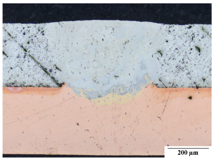
Furthermore, laser beam welding produces a small heat-affected zone. In the context of production, laser beam welding is well suited to be integrated into almost fully automated production lines in the manufacturing process of battery packs and EVs. The joining of aluminium and copper is particularly challenging in laser welding as the metal pair forms intermetallic phases, which can yield lower weld qualities [5,6,7]. These phases can be identified in cross sections, see Figure 1. For the investigation, the different colours in the mixing zone (dark grey and yellow areas) give a first indication on the concentration of the metals. For further investigation an energy dispersive X-ray spectroscopy can be performed, but will not part of this study.
This paper showcases an evaluation of various laser welded joints for the connection of pouch cell terminals to the battery pack in an overlap configuration. The specimen design is related to pouch cells. Due to the focus on the connection quality, no functional cells are used for this investigation. First, an ohmic-resistance model for the joints is introduced. With the help of this model the current flow across the overlap transition is analysed. Lastly different geometries of welds were chosen and compared in terms of their conductivity.
2. State of the Art
2.1. Measurement of Electrical Resistance of Laser-Welded Joints
A current passing through a conductor encounters an electrical resistance, analogous to an opposing force by mechanical friction. This resistance is defined in Ohm’s law as the proportion of voltage across and current through the same conductor. It is dependent on the specific electrical resistance of the conductor’s material and its dimensions according to [8].
: resistance (Ω); : specific resistivity (Ω·m2/mm); : conductor’s length (mm) and A: conductor’s cross-sectional area (m2).
The specific electrical resistance is furthermore dependent on the material’s temperature and exact chemical composition. Hence impurities can have an effect on the resistivity.
The measurement of an electrical resistance can be executed by a combined measurement of the voltage and current, as suggested by Ohm’s law. A popular method for this combined measurement is the so called four-terminal sensing. The four-terminal sensing describes the introduction of a defined current through the conductor and a separated voltage measurement. By separating the sensing wires the measured voltage does not falsely include the voltage across the current carrying wires. As a voltage measurement usually has a high impedance the current through the voltmeter can be neglected for significantly lower measured resistances.
In view of laser-welded joints of battery contacts, the analysis of the electrical resistance might present a suitable indicator for the weld quality. This postulation is based on the effect of impurities in the material and the dimension of the actual contact area on the joints conductivity. However, solely the quantity of the resistance might result in incorrect results when comparing different laser-welded joints. For instance, a joint of worse quality can show a significantly higher conductivity due to a larger cross-sectional area of the conductor. To allow valid comparisons between joints of different dimensions, the electrical resistance must be further processed to yield the so-called contact quality index.
The contact quality index (CQI, or resistance equivalence factor) describes the proportion of the joint’s resistance in respect to its base materials and dimensions [9,10]. To calculate the CQI of a lap joint an additional measurement of the material’s resistances is necessary, besides determination of the actual joint resistance. Assuming a constant cross-sectional area of the conductors and constant measurement distances, these can be acquired as per [9,11] shown in Figure 2.
The base resistance for the joint is derived by assuming a seamless, resistance-less joint from one material into the other over its length. The expected resistance for this geometrically optimal case would equal half the sum of the measured material’s resistances, namely the average. The CQI can now be calculated by dividing the actual joint’s resistance by the base joint’s resistance. The equation is shown in (4).
: measured conductor resistance (Ω); : conductor resistance for length (Ω); : measured joint resistance (Ω); : corrected joint resistance (Ω); : voltage across conductor (V); : voltage across joint (V); : measuring current (A); : measuring distance (mm); : joint distance (mm); : contact quality index (1).
A CQI value of 1 can be interpreted as a joint of similar conductivity as the base materials; a value less than 1 indicates a higher, a value higher than 1 a lower conductivity. With the CQI joints of different materials and dimensions can now be compared for its joining method and effect on electrical resistivity.
2.2. Laser Beam Welding with Spatial Power Modulation
For the joining of materials with high thermal conductivity, laser beam welding is a suitable process. Using small focus diameters of a few 10 µm, the resulting high intensities are able to melt and vaporize the material to achieve deep and narrow weld seams. The process is defined with two process stages, the heat conduction welding and the deep penetration welding. For heat conduction welding the material is molten due to the absorption of the laser beam’s energy on the surface. This process significantly depends on the absorptivity of the material. Significantly higher welding depths can be achieved by exceeding a characteristic intensity threshold using a deep penetration welding process. Therefore the material is vaporized and a keyhole is formed inside the molten pool. Multiple interactions of the laser beam inside this keyhole lead to an increase of the energy input resulting in a higher weld seam depth [12].
To manipulate the shape of the weld seam cross section and to stabilize the process during a deep penetration weld, a spatial power modulation can be used. Therefore the linear feed is superposed with a circular oscillation movement. The path is then characterized by an oscillation amplitude , frequency and feed rate . In [13] a change from a v-shaped to a rectangular shaped weld seam cross section has been seen. Furthermore, an influence on the hardness, on the mixing of the materials in overlap configurations and on the roughness of the weld seam surface have been identified [13,14].
2.3. Laser Beam Welding of Electrical Contacts
For laser welding of electrical contacts, the contact resistance is the most important index, particularly indicated by the previously defined CQI. Therefore [15] has investigated similar material joints and reached a CQI of 0.55 for a copper connection and 0.57 for aluminium. In this case the joining partners have been connected by two parallel weld seams in an overlap configuration. By using two lines with the highest distance possible, the material in the overlap area is connected in parallel and shows a reduced transition resistance due to the higher current-carrying cross-section.
The investigation of [16] focuses on welding of dissimilar materials using a pulsed Nd:YAG laser. Weld seam depth and temperature gradient in the melt pool are controlled by a temporal power modulation. The investigations show a reduced mixing of the materials, higher process stability and higher seam quality.
Depending on the application, aluminium or copper is usually used to conduct electricity. Due to the reduced density, aluminium is used for lightweight applications, while copper with its higher conductivity is used when space is limited. Joining aluminium to copper, leads to numerous challenges. The differences in melting point, thermal conductivity and expansion cause tensions during the solidification, which can lead to cracks in the weld seam. Furthermore, the materials are soluble in the liquid state and form intermetallic phases inside the mixing zone of the weld seam. Besides the increase of hardness and crack sensitivity, the intermetallic phases increase the electrical resistance [5,6,7,17].
3. Electrical Equivalent Model for Joint
The investigation focused on laser-welded lithium ion pouch cells. The relatively broad contacts of these cells consist of aluminium and copper and offer a large contact area. Hence, in the joining of lithium ion pouch cells the overlap joint represents a suitable joining method. The joint in this investigation was aligned along the current direction, producing a straight junction with an expected homogenous current density in the conductors’ cross-sectional areas (Figure 2).
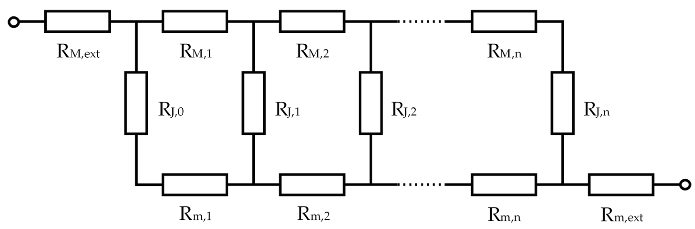
The given lap joint can be modelled by using electrical equivalent circuit diagram from [4]. Each joining partner, M and m, was subdivided into equally sized stretch elements resistances. The partners were joined by bridge elements (indexed with J) representing the current-carrying interconnections. The resulting equivalent circuit is shown in Figure 3. The dimensions of each resistance in the equivalent circuit could be mapped according to regarded materials, joining methods and joint areas to represent the equivalent, real lap joint. All simulation results were based on basic electrical equations implemented in Python.
The simulation of an electrical current through the equivalent diagram of a joint with homogenous resistance revealed a significant phenomenon. The current had an inherent tendency to flow along the edges of the joint, represented by the first and last bridge elements of index 0 and n. The tendency increased with decreasing bridge resistance in comparison to the joining partners’ resistances (indexed with C). This phenomenon was explained by comparing the given equivalent circuit to a cascaded bridge circuit. With decreasing bridge resistance, the model approximated a cascaded bridge circuit, which by definition did not carry any current through the bridges when balanced (of equal resistance ratio). In fact, it is theoretically impossible for the current to be equal across all bridges in the equivalent circuit with n > 1 of a given joint, if no variance in the resistances is introduced. This can be proven mathematically by assuming equal bridge currents and overall equal resistances in the model (n > 1) and yielding a contradiction by calculating the overall joint resistance via circuit diagram simplification and the mesh current method.
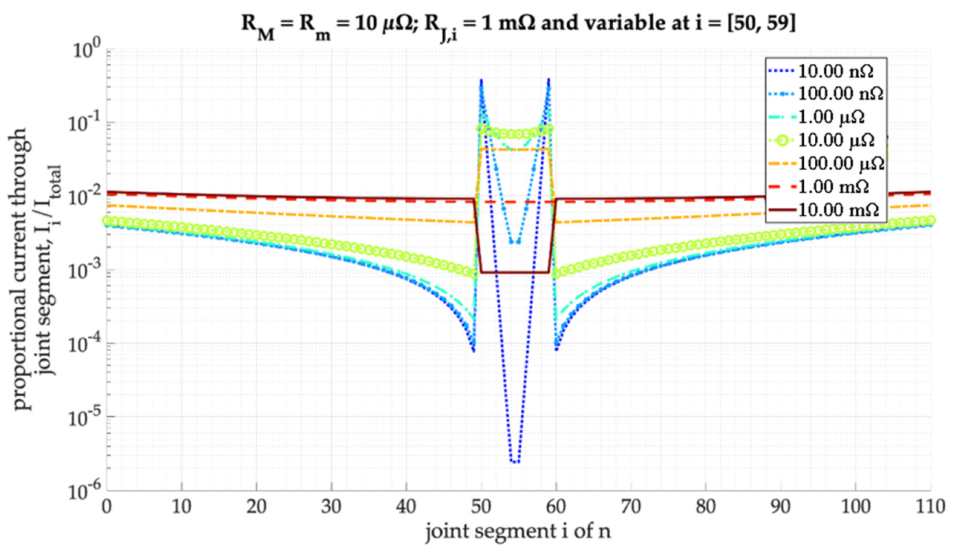
For the simulation of laser-welded seams on the joint, the electrical values for the model were determined experimentally. Considering the limitations of the two-dimensional model, the bridge elements modelled a contact line across the whole conductor’s width. The model was set to be of order n = 110, hence having 111 distinct bridge resistances (indices 0 through 110). The bridge elements RJ,i, representing either a weld or a purely frictional contact across the joint, could be determined by combining the measurements of a representative laser-welded joint, a purely frictional contact joint and a joint consisting solely of a laser welded seam. The produced bridge resistances show an improvement in conductivity for laser-welded bridges as compared to frictional contacts by a factor of 9800, 8750 and 178,000 for aluminium–copper, copper–copper and aluminium–aluminium joints respectively. The significantly higher factor in the pure aluminium joint can be explained by high resistances of its frictional contact due to surface oxidation [18]. A simulation of current through a joint with simplified resistances yields the proportional current through each bridge element RJ,i presented in Figure 4 (model of order n = 110 model with RM,i = Rm,i = RM/n).
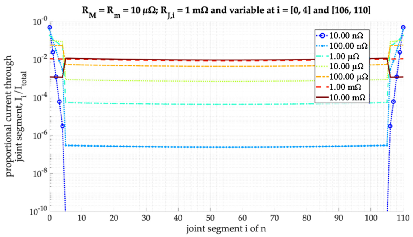
The figure clearly shows the higher conductivity of the laser-weld, spanning over the central ten bridge elements. Additionally, the previously explained tendency of the current flowing through the joint’s edges could be identified in the rising current rates towards the bridge indices of 0 and 110. Modifying the identical model to have the laser-welded bridges to be divided to the joint’s edges, yields simulated current rates as shown in Figure 5.
The first five and last five slots were now assigned to the laser-welded resistances and hence represented a joint of overall similar cross-sectional surface area to the central weld example. Due to the tendency of edge currents the overall carried current through the weld was significantly higher than in the example of the central weld; the current through the frictional contact was negligibly small. As a result, the implementation of a “double weld” not only effectively doubled the conductivity of the joint (by connecting the materials in parallel, increasing the conductor’s cross-sectional area in direction of main current flow) but also complemented the current to predominantly flow through the laser-welded seams on the joints edges.
A variance of the resistances for the modelled materials introduced a shift in the bridges’ current densities, whereas higher densities were found at the side of the lower conductive material (and accordingly the end of the material with higher conductivity). The distribution roughly resembled the rate of currents found in parallel resistances of different magnitude. Overall the simulations yield an understanding of current distribution in the overlap joint and its variance introduced by weld placement or different materials.
4. Metrological Investigation of Resistances of Laser Welded Joints
The experimental part of the investigation focused on the comparison of different welding characteristics and geometries on overlap joints. The equipment consisted of a laser welding machine, a micro-ohmmeter and a custom test bench. The laser machine was an IPG YLR 1000 SM, single-mode fibre laser with a maximum emission power rating of 1 kW. The ohmmeter was a LoRe precision micro-ohmmeter from Werner Industrielle Elektronik and had a resolution of 1 nΩ in low measurement ranges starting at 10 nΩ. The custom test bench was designed to measure overlap joints in a manner to obtain both the joints resistance and CQI in respect to the materials, while retaining a maximum standard deviation of ±45 µm in the measurement tips’ placement.
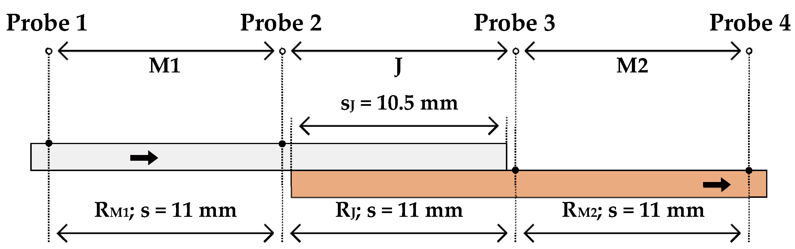
The investigation included the survey of different welding parameters and of different weld geometries altogether. The specimens were fabricated from aluminium Al99.5 and copper Cu-ETP metal strips of dimensions 20 mm width, 85 mm length and 0.3 mm strength. The specimen geometry and material were based on a connection of pouch cell batteries. As per Figure 6 the joints overlap sJ was dimensioned to be of 10.5 mm length.
The measuring sections span over s = 11 mm; the deviation between measurement and actual joint distance (s and sJ respectively) was eliminated mathematically post measurement. The produced joints included Al–Al, Cu–Cu and Al on Cu joining; Cu on Al joints were averted due to high instabilities in the welding process. The differences in material properties and the occurrence of intermetallic phases led to weld defects such as cracks.
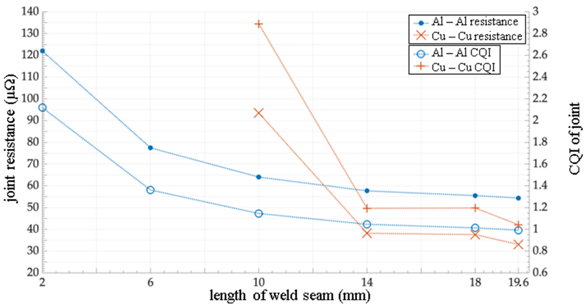
The investigation of different welding parameters was conducted on the geometry of a central weld. Variances were introduced in respect to weld length across the joint, weld width along the joint and for the case of Al–Cu joints the induction of resistive intermetallic phases by altering the laser’s power. The joint’s resistance progressively increased with a reduction of weld length (Figure 7).
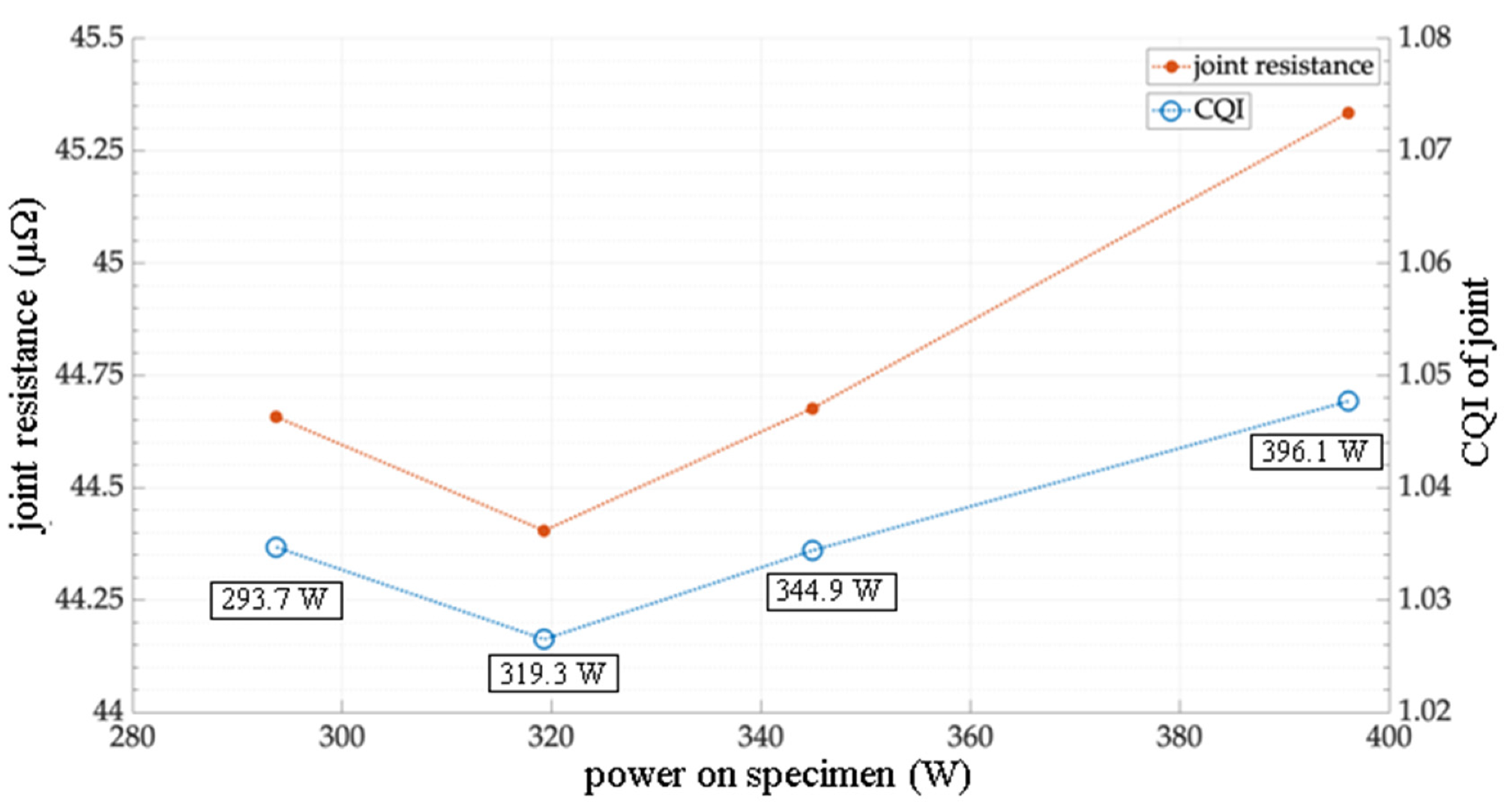
Although the variation of weld widths introduced instabilities in the welding process, an overall slight resistance reduction was also measured with the increase of weld width. The intentional introduction of intermetallic phases was to test the measurability of such. The measured resistances did indeed show a dependency to the introduced laser power and hint a local minimum for optimal parametrization (Figure 8).
The weld geometries and their measured CQIs are presented in Table 1. They were categorized by central, long-side and double geometries; additionally, asymmetrical geometries for Al–Cu joints were examined. The values for each configuration indicate the CQI for each material combination Al–Al (A), Cu–Cu (C) and Al–Cu (M). The long-sided and the sawtooth welds were only tested with a copper–copper connection as they were not expected to yield significantly different results across material combinations. The double weld with pattern and the asymmetrical configurations were likewise only implemented as an aluminium–copper connection.
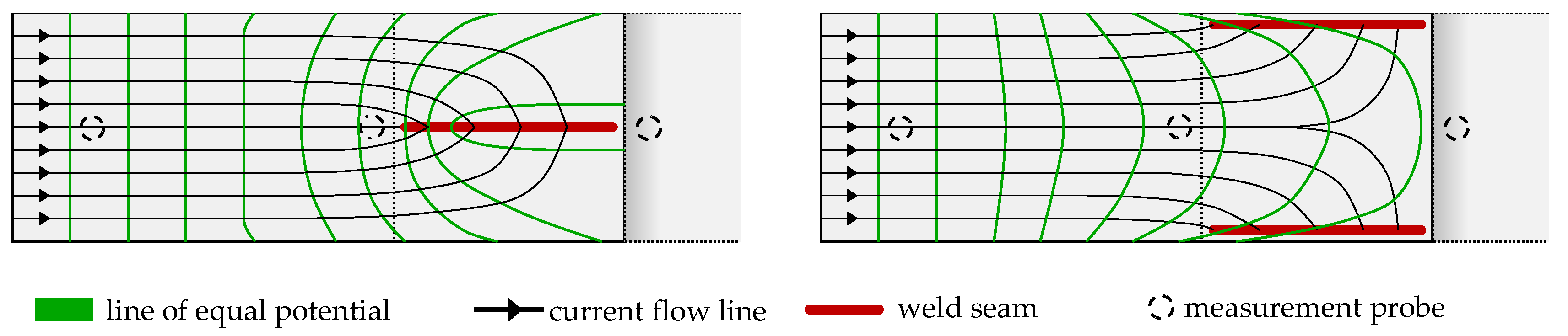
As presented in the table, a single central weld could reach sufficient contact quality with respect to the reference materials. All material combinations could achieve values close to a CQI of 1, emulating the conductance of the materials. All long-sided joints show a higher CQI compared to the single central line. This may result due to inhomogeneous current densities, not utilizing the full extent of the available material as shown in Figure 9 below. The inhomogeneous current flow could be corrected by recalculating the inner two measurement point. Those measurement points were expected to be affected by the current flow as presented in Figure 8. The recalculation was done by taking the measured total resistance between the outer measurement points and subtracting the expected resistances of the metals on both sides. The expected resistances were calculated by averaging the respective measurements of the remaining, unaffected specimens. The resulting substitute resistances were expected to deliver more resembling and comparable estimates in cases of inhomogeneous current flow.
By using double welds positioned on the joint’s edges, the CQI was reduced to the near theoretical optimum value of 0.5. With this configuration, the available material was utilized as a parallel connection, effectively doubling the conducting cross sectional area. As seen with the double weld with pattern, a further increase of the connection area by an additional weld seam did not lead to a further reduction of the CQI for an aluminium copper connection.
Due to the materials’ differing resistivity, the current was predominantly through the more conductive material, in this case copper. To determine the influence of the different material properties and the weld seam geometry, three asymmetrically configurations were investigated. By shifting the weld seam closer to the copper edge, an increase of the CQI was measured. A slight increase was also seen with a reduced weld seam length on the aluminium edge. By using an arrow geometry, the CQI was increased significantly due to the use of just one weld seam instead of two, but was still lower compared to a single central weld seam.
5. Discussion
During the investigation the model could be verified to represent the single and double joints, when initialized with representative data. However, it cannot represent more complex joints, where the conductor’s cross-sectional areas did not predominantly carry strictly perpendicular currents. For the simulation of such joints a more complex three-dimensional model is required. The phenomenon of current distributions within the joint, as seen in the model, provides implications for the manufacturing of battery joints.
For applying a laser welding process in electrical applications, the results lead to following design guide lines. To achieve a CQI of 1, it is sufficient to apply a single weld seam along the whole width of the joining partners. Requirement is a stable welding process for contacting the joining partners. The width of the weld seam, rectangular to the current flow direction did not have a significant influence (compare central slim double line in Table 1). The measured values indicate a slight CQI reduction for the similar aluminium and the aluminium copper connection.
By greatly increasing the distance between the two weld seams the CQI was reduced to nearly 0.5 leading to the assumption that the position of the weld seams had a greater effect on the resistance than increasing the connection width and accordingly seam area with additional weld seams. That concludes that weld seams should be positioned as wide apart as possible to use the parallel connection of the two conductors. This measurement result is further supported by the simulation, which identified a predominant current flow through the joint’s edges.
The identified dependency of the laser power on the resistance, leads to the assumption that an increased weld depth is not improving the CQI. The measurements showed higher values with increased laser power and therefore weld depths. The reason for this behaviour might be an increased mixing of the copper and aluminium, which leads to an increased occurrence of intermetallic phases. These phases inhibit the current flow in the weld seam and lead to an increase of the measured resistances. Furthermore, besides affecting the weld seam’s resistance, it can supposedly reduce the materials’ conductivity. As seen with the joint “Double with pattern” from Table 1, the addition of a pattern to the normal double joint increases the CQI. The introduction of further intermetallic phases deals a greater effect on conductivity, than the increase of welded area, in the joint’s central area, less significant to the bridge-currents.
6. Conclusions
To reduce the electric loss in the connection of battery cells for electric vehicles, the joining process and the resulting transition resistance are essential. By introducing a model representing the joints’ partial resistances, the current flow through the connection could be investigated. As a consequence, various joint geometries were investigated using a laser welding process to leverage and examine the observed edge current phenomenon. Naturally the current density along the material edges of the overlap, which are perpendicular to the current flow, was predominantly higher compared to the inner contact area. By measuring a CQI for each proposed connection, the influence of different weld seam geometries could be identified. Using double welds close to the edges of the overlapped materials yielded the investigations minimum CQI of about 0.52 and should hence be considered for manufactural purposes. The sheer increase of the welded contact area should be critically assessed, as it had a significantly smaller influence to the CQI and could even reduce the joint’s conductivity.
Author Contributions
Idea, study design and laser welding were done by S.H. The development of the measurement system and measurements have been performed by S.K. The electrical modelling and theoretical background was contributed by C.Ü. A.O. contributed to the laser welding process and study design. A.G. and D.U.S. contributed to all parts. All authors have read and agreed to the published version of the manuscript.
Funding
This research received no external funding.
Conflicts of Interest
The authors declare no conflict of interest.
References
- Shi, W.; Hu, X.; Jin, C.; Jiang, J.; Zhang, Y.; Yip, T. Effects of imbalanced currents on large-format LiFePO4/graphite batteries systems connected in parallel. J. Power Sour. 2016, 313, 198–204. [Google Scholar] [CrossRef]
- Mauger, A.; Julien, C.M. Critical review on lithium-ion batteries: Are they safe? Sustainable? Ionics 2017, 23, 1933–1947. [Google Scholar] [CrossRef] [Green Version]
- Katayama, S. Introduction: Fundamentals of laser welding. In Handbook of Laser Welding Technologies; Woodhead Publishing: Cambridge, UK, 2013; pp. 3–17. [Google Scholar]
- Brand, M.J.; Schmidt, P.A.; Zaeh, M.F.; Jossen, A. Welding techniques for battery cells and resulting elextrical contact resistances. J. Energy Storage 2015, 1, 7–14. [Google Scholar] [CrossRef]
- Poprawe (Hrsg.), R. Tailored Light 2—Laser Application Technology; Springer: Heidelberg, Germany, 2011. [Google Scholar]
- Bliedtner, J.; Müller, H.; Barz, A. Lasermaterialbearbeitung; Carl Hanser: München, Germany, 2013. [Google Scholar]
- Standfuß, J.; Rath, W.; Valentin, M.; Falldorf, H. Laserschweißen von Mischverbindungen. Laser Tech. J. 2011, 8, 24–26. [Google Scholar] [CrossRef]
- Frielingsdorf, H.; Lintermann, F.J. Elektrotechnik—Allgemeine Grundbildung, 2nd ed.; Stam: Köln, Germany, 1993. [Google Scholar]
- Schmalen, P.; Plapper, P. Resistance Measurement of Laser Welded Dissimilar Al/Cu Joints. JLMN-J. Laser Micro Nanoeng. 2017, 2, 189–194. [Google Scholar]
- Schmidt, J.P. Verfahren zur Charakterisierung und Modellierung von Lithium-Ionen-Zellen; KIT Scientific Publishing: Karlsruhe, Germany, 2013. [Google Scholar]
- Schmidt, P.A.; Schweier, M.; Zaeh, M.F. Joining of Lithium-Ion Batteries Using Laser Beam Welding: Electrical Losses of Welded Aluminum and Copper Joints. In Proceedings of the 31st International Congress on Applications of Lasers & Electro-Optics, Anaheim, CA, USA, 23–27 September 2012; p. 915. [Google Scholar]
- Hügel, H.; Graf, T. Laser in der Fertigung; Vieweg + Teubner: Wiesbaden, Germany, 2009. [Google Scholar]
- Schmitt, F. Laserstrahl-Mikroschweißen mit Strahlquellen hoher Brillanz und örtlicher Leistungsmodulation; RWTH Aachen University: Aachen, Germany, 2012. [Google Scholar]
- Häusler, A.; Mehlmann, B.; Olowinsky, A.; Gillner, A.; Poprawe, R. Efficient Copper Microwelding with Fibre Lasers using Spatial Power Modulation. In Lasers in Enginneering 36; Old City Publishing: London, UK, 2017; pp. 133–146. [Google Scholar]
- Schmidt, P.A. Laserstrahlschweißen elektrischer Kontakte von Lithium-Ionen-Batterien in Elektro- und Hybridfahrzeugen; Technischen Universität München: München, Germany, 2015. [Google Scholar]
- Gedicke, J.; Olowinsky, A.; Artal, J.; Gillner, A. Influence of temporal and spatial laser power modulation on melt pool dynamics. In Proceedings of the 26th International Congress on Applications of Lasers & Electro-Optics, Orlando, FL, USA, 29 October–1 November 2007; pp. 816–822. [Google Scholar]
- Mys, I.; Schmidt, M.; Eßer, G.; Geiger, M. Verfahren zum Schweißen Artungleicher Metallischer Fügepartner, Insbesondere von Aluminium-Kupfer-Verbindungsstellen. Deutschland Bayern Patent Application No. DE102004009651B4, 9 October 2008. [Google Scholar]
- Mercier, D.; Mandrillon, V.; Volpi, F.; Verdier, M.; Bréchet, Y. Quantitative evolution of electrical contact resistance between Aluminum thin films. In Proceedings of the 2012 IEEE 58th Holm Conference, Portland, OR, USA, 23–26 September 2012. [Google Scholar]
Figure 1.
Cross section of a laser welded aluminium and copper joint (P = 294 W, v = 120 mm/s, A = 0.15 mm, f = 1000 Hz).
Figure 1.
Cross section of a laser welded aluminium and copper joint (P = 294 W, v = 120 mm/s, A = 0.15 mm, f = 1000 Hz).

Figure 2.
Schematic illustration for the calculation of the contact quality index (CQI).

Figure 3.
Model of the lap joint using an electrical equivalent circuit diagram.

Figure 4.
Simulation of current through a simplified model with a central weld seam.

Figure 5.
Simulation of current through a simplified model with weld seams on the joint’s edges.

Figure 6.
Schematic set-up of measuring the specimen.

Figure 7.
Resistance and CQI of the central weld joints with varying length.

Figure 8.
Resistance and CQI of central weld joints with varying laser powers and hence intermetallic phases (vf = 100 mm/s, A = 0.2 mm, f = 1000 Hz).
Figure 8.
Resistance and CQI of central weld joints with varying laser powers and hence intermetallic phases (vf = 100 mm/s, A = 0.2 mm, f = 1000 Hz).

Figure 9.
Schematic of proposed inhomogeneous current densities affecting voltage measurements.


Table 1.
CQIs of different weld geometries for Al–Al (A), Cu–Cu (C) and Al–Cu (M). Laser parameters: amplitudes AA = AC = AM = 0.2 mm unless specified; frequencies fA = fC = fM = 1 kHz; feed rates vf,A = vf,C = vf,M = 100 mm/s unless specified and power (on specimen) PA = 243 W, PC = 498 W, PM = 294 W.
| Joint | Central | Long-Side | Double | Asymmetrical |
|---|---|---|---|---|
 Single Single |  Single Single |  Double Double |  Shifted double Shifted double | |
| A | 0.9924 | - | 0.5250 | - |
| C | 1.0010 1 | 1.1831 3 | 0.5220 3 | - |
| M | 1.0051 2 | - | 0.5321 | 0.5809 |
 Close double Close double |  Double Double |  Double with pattern Double with pattern |  Shrunk double Shrunk double | |
| A | 0.9713 | - | - | - |
| C | 1.2271 3 | 1.17781 3 | - | - |
| M | 0.9824 | - | 0.5436 | 0.5550 4 |
 Sawtooth Sawtooth |  Arrow Arrow | |||
| A | - | - | ||
| C | 0.9946 | - | ||
| M | - | 0.9414 |
1A = 0.1 mm, vf = 120 mm/s. 2. A = 0.15 mm and vf = 120 mm/s. 3. Process produced unexpectedly high resistances. Hypothesis: Higher thermal impact affected material deformations and hence elevated frictional contact resistances. 4 Values after correction for inhomogeneous current flow. Raw measurements show higher resistance for single and lower resistance for double long-side welds.
© 2020 by the authors. Licensee MDPI, Basel, Switzerland. This article is an open access article distributed under the terms and conditions of the Creative Commons Attribution (CC BY) license (http://creativecommons.org/licenses/by/4.0/).
Share and Cite
MDPI and ACS Style
Hollatz, S.; Kremer, S.; Ünlübayir, C.; Sauer, D.U.; Olowinsky, A.; Gillner, A. Electrical Modelling and Investigation of Laser Beam Welded Joints for Lithium-Ion Batteries. Batteries 2020, 6, 24. https://doi.org/10.3390/batteries6020024
AMA Style
Hollatz S, Kremer S, Ünlübayir C, Sauer DU, Olowinsky A, Gillner A. Electrical Modelling and Investigation of Laser Beam Welded Joints for Lithium-Ion Batteries. Batteries. 2020; 6(2):24. https://doi.org/10.3390/batteries6020024
Chicago/Turabian StyleHollatz, Sören, Sebastian Kremer, Cem Ünlübayir, Dirk Uwe Sauer, Alexander Olowinsky, and Arnold Gillner. 2020. "Electrical Modelling and Investigation of Laser Beam Welded Joints for Lithium-Ion Batteries" Batteries 6, no. 2: 24. https://doi.org/10.3390/batteries6020024
Note that from the first issue of 2016, this journal uses article numbers instead of page numbers. See further details here.