Article

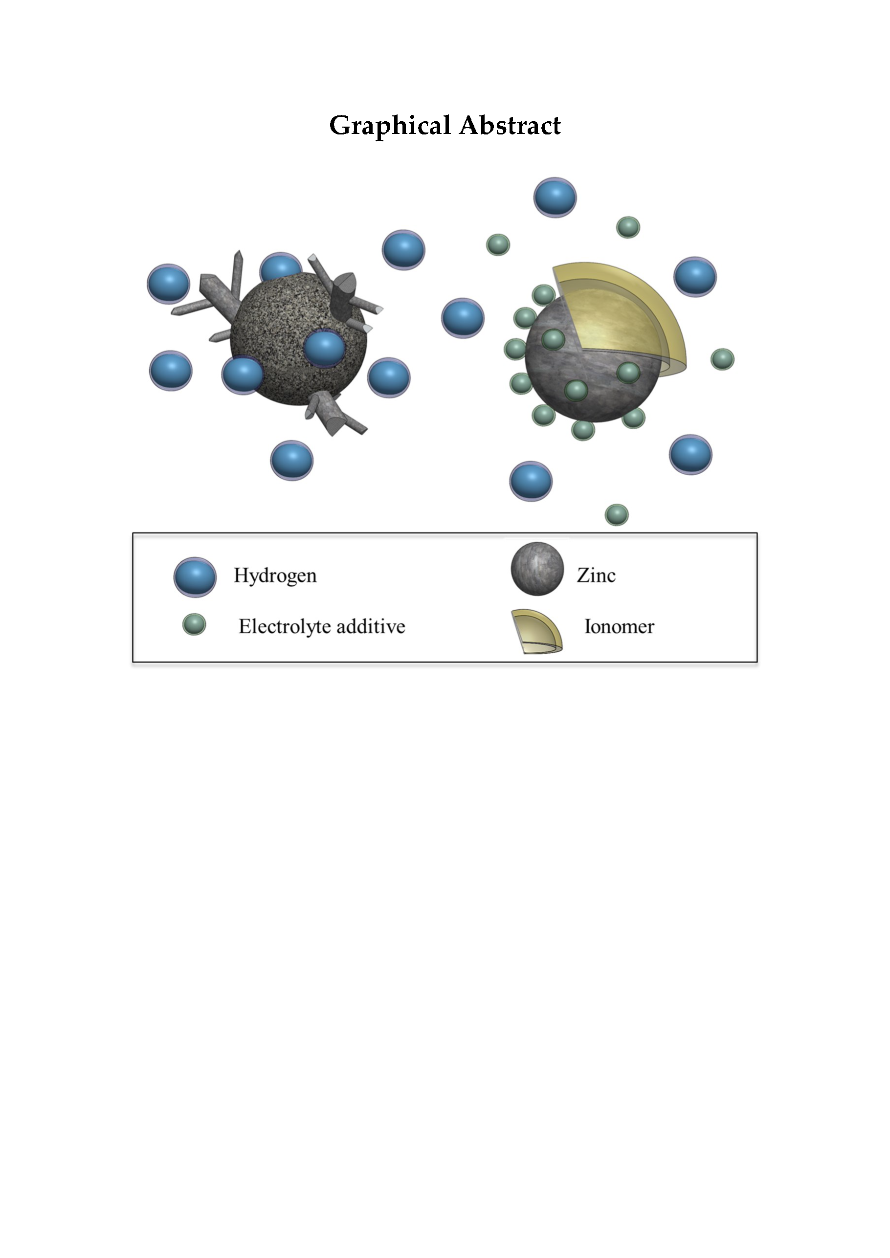
Enhancing the Cycle Life of a Zinc–Air Battery by Means of Electrolyte Additives and Zinc Surface Protection

by
Aroa R. Mainar
1,2,
Luis C. Colmenares
1,
Hans-Jürgen Grande
1,2 and
J. Alberto Blázquez
1,*
1
CIDETEC Energy Storage, P° Miramón, 196, 20014 Donostia-San Sebastián, Spain
2
Departamento de Ciencia y Tecnología de Polímeros, Facultad de Química, UPV/EHU, P° Manuel de Lardizábal 3, 20018 Donostia-San Sebastián, Spain
*
Author to whom correspondence should be addressed.
Batteries 2018, 4(3), 46; https://doi.org/10.3390/batteries4030046
Submission received: 27 July 2018 / Revised: 4 September 2018 / Accepted: 10 September 2018 / Published: 13 September 2018
(This article belongs to the Special Issue Rechargeable Aqueous Zinc-ion Batteries)

Abstract

:
The commercialization of rechargeable alkaline zinc–air batteries (ZAB) requires advanced approaches to improve secondary zinc anode performance, which is hindered by the high corrosion and dissolution rate of zinc in this medium. Modified (with additives) alkaline electrolyte has been one of the most investigated options to reduce the high solubility of zinc. However, this strategy alone has not been fully successful in enhancing the cycle life of the battery. The combination of mitigation strategies into one joint approach, by using additives (ZnO, KF, K2CO3) in the base alkaline electrolyte and simultaneously preparing zinc electrodes that are based on ionomer (Nafion®)-coated zinc particles, was implemented and evaluated. The joint use of electrolyte additives and ionomer coating was intended to regulate the exposition of Zn, deal with zincate solubility, minimize the shape change and dendrite formation, as well as reduce the hydrogen evolution rate. This strategy provided a beneficial joint protective efficiency of 87% thanks to decreasing the corrosion rate from 10.4 (blank) to 1.3 mgZn cm−1·s−1 for coated Zn in the modified electrolyte. Although the rate capability and capacity are limited, the ionomer-coated Zn particles extended the ZAB cycle life by about 50%, providing battery roundtrip efficiency above 55% after 270 h operation.

Graphical Abstract

1. Introduction

Energy storage systems that are based on secondary zinc electrodes are potential candidates to fulfill the need for light-weight and high discharge rate applications. The zinc anode has many merits such as low cost, low toxicity, high specific energy, high electrochemical reversibility, easy availability, and handling [1], which make it suitable for various applications in alkaline battery systems [2]. However, despite a few commercialization cases of rechargeable zinc-based energy storage systems (e.g., Evercel, ZPower, Fluidic Energy, ZincFive, EOS, ZAF, Zinium (ZnR Batteries), etc.), Fluidic Energy is the only current company commercializing reversible zinc–air technology. Therefore, in general, one can consider that the zinc electrode still suffers from a limited cycle life [3]. This long-term limitation is usually assigned to zinc corrosion [4] (associated to the evolution of hydrogen), high dissolution rate of zinc [5] in the traditional aqueous alkaline electrolytes (32 wt. % KOH), dendrite formation, and zinc electrode shape change. In addition, limitations arise from the stability and performance of the bifunctional air electrode, which needs to support significant cell voltage changes during the cycle life due to its large overpotential towards both the reduction and evolution of oxygen [1].
During the charging, re-deposition of zinc-active material is a non-homogeneous process, and hence high local current density occurs. This uneven redistribution of zinc on the electrode surface provokes changes in the electrode shape and dendritic diffusion-controlled deposition. Dendrite growth may cause short-circuit over time [6]. In this sense, these detrimental processes will induce the loss of the capacity retention and cycle life in the long term. Fluidic Energy claimed to solve these technology drawbacks by implementing ionic liquid as the electrolyte, in addition to other developments at the engineering level.
In the last few years, many attempts have been made to develop, modify, and/or optimize zinc electrodes with reduced solubility of zinc discharge products. The majority has included the use of additives either to the electrode itself or to the electrolyte [4,5,7,8,9,10,11]. Unfortunately, one of the principal disadvantages of this strategy is that some anode additives may reduce the initial content of available zinc-active species in the zinc electrode, and thus, they negatively influence the capacities and the specific energy of the battery [9,12]. Therefore, in the interest of limiting the amount of dissolved zinc that diffuses into the alkaline electrolyte, it is necessary to find different strategies. In zinc-based batteries, modified alkaline electrolyte has been one of the most used strategies to reduce the high solubility of zinc in the strongly alkaline electrolyte. The pursuit of an extended cycle life has enabled this technology to, for example, adjust the alkalinity and ionic strength of the electrolyte [13], thus reducing zinc solubility as well as minimizing shape change and dendrite formation [11,13,14,15,16,17,18,19].
On the other hand, researchers have also investigated the formulations of zinc electrodes by means of adding alternative binders [20], i.e., conductive organic and/or inorganic additives [3,19,21,22,23,24,25,26]. As mentioned above, the common aim is to overcome anode limitations, thus increasing the reversibility (i.e., cycle life) of the system. In this regard, J.-L. Zhu et al. [27] evaluated the suppression of dendrite growth by coating lanthanum and neodymium hydroxides on zinc electrodes through electrolysis, while L. Zhu et al. also demonstrated the benefit of modifying zinc powder with neodymium, but via the ultrasonic impregnation technique [2]. Vastalarani and co-workers [23] reported that the reversibility and corrosion protection of the zinc electrode in alkaline medium were improved by electrostatic deposition of a conducting polymer onto the electrode. On the other hand, K. Miyazaki et al. [25] mitigated the dendrite formation of zinc electrodes by means of anion-exchange ionomers as a surface protective layer of zinc particles. J. Zhu et al. [24] tried different ionomer films that were coated on zinc electrodes, demonstrating, in general for all of them, an effective reduction of dissolved zinc discharge products into the electrolyte. In the same way, D. Stock et al. [28] demonstrated an effective increment of the cycle life for Zn model electrodes coated with a homogeneous layer of an anion-exchange ionomer. They explained such an increment by a greater amount of restored zinc during electrodeposition thanks to a confinement of oxidized zinc species near the electrode surface. Table 1 summarizes some of the different approaches that were reported in the state-of-the-art, describing the benefits of the zinc surface protection.
In order to satisfy the market demand and depending on the operating conditions of which battery is requested, it is necessary to make a compromise among the specifications of the battery. For example, the implementation of different strategies to improve the battery cycle life could impact its capacity. Thus, such an impact should be assumed during the development and optimization of mitigation strategies. Having that in mind, and even knowing that the use of additives would reduce the initial content of zinc active material and may lower the specific energy (or power) of the battery, the combination of strategies to mitigate any of the detrimental processes in the secondary zinc–air battery is the main idea of this work.
In this sense, the present contribution will deal with a combined strategy in order to improve the cycle life of a rechargeable zinc electrode, and hence, a zinc–air battery (ZAB). To achieve this target, optimized alkaline electrolyte formulation, including additives [9,13,15], is implemented together with the use of different amounts of Nafion® as a protective ionomer layer. Zn-reversibility, lifecycle performance, capacity retention, and battery roundtrip efficiency are assessed to improve the electrochemical performance of a secondary ZAB.

2. Materials and Methods

2.1. Selection of the Aqueous Alkaline Electrolyte Systems

Since a deeper understanding of the use of additives in the standard aqueous alkaline electrolyte for Zn-based batteries is beyond the scope of this publication, the readers are referred to earlier (e.g., [11] and refs. therein) and more recent [9] publications that are related to this topic. Therefore, while taking into account that, in the state-of-the-art, the aqueous alkaline electrolyte system formulation is composed of 6–8 M of KOH due to its higher ionic conductivity (above 600 mS cm−1 [9,15]), the aqueous alkaline electrolytes used in the present work were (i) the standard 6.6 M KOH (637 mS cm−1 [9,15]) and (ii) the modified alkaline electrolyte based on 4 M KOH with 2 M KF and 2 M K2CO3 saturated with ZnO (i.e., dissolution of ZnO in KOH until no more ZnO can be dissolved) (370 mS cm−1 [9,11,13,33]), thereafter referred to as 4s-2. In the case of the 4s-2 electrolyte, the selection of 4 M KOH was derived from the approach developed by Adler et al., based on reduced-alkalinity electrolytes [13] and also implemented by [16,33]. Recently, A. Mainar et al. have confirmed the benefits of this concentration. Moreover, additives reduce the hydrogen evolution contribution during Zn deposition [9]. The authors have also demonstrated the uniform deposition of zinc in the presence of zincate-KF-K2CO3 additives, as well as the reduction of hydrogen generation (ca. 30%) in comparison to additive-free KOH electrolyte [9]. B. Hwang et al. have also reported 4 M KOH as the most suitable concentration to minimize the corrosion of zinc, and hence, promote the extended cycle life of zinc electrodes [34].
The chemicals that were used for the electrolyte preparation were KOH (Sigma-Aldrich, St. Louis, MO, USA, 85% pure), ZnO (Sigma-Aldrich, 99% pure), KF (Sigma-Aldrich, 99% pure), and K2CO3 (Sigma-Aldrich, 99% pure). All electrolyte systems were prepared while using deionized water. Hereafter, the electrolyte (i) is labelled as “blank” and electrolyte (ii) as 4s-2 (where 4 represents 4 M KOH; s represents ZnO saturated; 2 represents 2 M KF and 2 M K2CO3).

2.2. Zinc Powder and Ionomer-Coated Zinc Particles (ICZP)

The purchased zinc powder (Grillo GmbH, Ratingen, Germany) with battery specification grade (meaning 300 ppm In and 330 ppm Bi incorporated to suppress H2 evolution) was used as received. The morphology was observed while using Zeiss Gemini Ultraplus field emission scanning electron microscopy (FE-SEM; 4.00 kV EHT; secondary electron (SE) image). The surface composition of the un- and coated zinc particles was examined through energy dispersion spectrometry (EDS) with an Ametek® (Berwyn, PA, USA) Edax Apollo X instrument.
The ionomer-coated zinc particles (ICZP) were prepared by adding 20 g of zinc powder (Grillo GmbH) into 100 mL of a given stirred alcoholic-based Nafion® (Ion Power, New Castle, DE, USA, LiquionTM 5 wt. %) solution (0; 1 and 5 wt. % Nafion® in isopropanol as solvent) at room temperature. After 60 min of stirring, the zinc dispersion was filtered and then dried under vacuum at 70 °C for 17 h. The ICZP samples that were used in this work are labelled as a function of the amount of Nafion® added, namely ICZP-0, ICZP-1, and ICZP-5 for 0, 1, and 5 wt. % Nafion®, respectively.

2.3. Electrodes Preparation

Zn-Pellets: 0.3 g of zinc powder (uncoated and coated) was compressed applying a pressure of 2 tons for 5 min. The resulting pellets had a thickness of 0.1 cm and a diameter of 0.8 cm.
Zn-Paste: it consisted of 46.28 wt. % zinc (ionomer-free or ICZP), 24.12 wt. % ZnO, 28.2 wt. % electrolyte system (blank or 4s-2) and 1.4 wt. % carboxymethyl cellulose (CMC, Cekol) as gelling agent. This formulation is based on recipes from Malone et al. [35] for primary Zn–air batteries, and from Kainthla et al. [36] who incorporated ZnO in a ratio of Zn:ZnO between 33 and 40 wt. %. The addition of ZnO is intended to reduce the build-up of internal pressure due to volume changes during discharge (1.6 times from Zn to ZnO based on their molar density) and/or facilitates the nucleation of ZnO during battery discharge [37]. The paste components were properly mixed and stored in a syringe during the electrode preparation. Electrodes that were based on Zn-paste (45 mgZn cm−2) with a geometric surface area of 2.5 cm2 were prepared.
Bifunctional air electrode (BAE): it consisted of a monolayer prepared by mixing 20 wt. % α-MnO2 catalyst (see [38] for more details), 70 wt. % undoped multi-wall carbon nanotube (CNT, Arkema, Colombes, France) and 10 wt. % PTFE (Dyneon, Gendorf, Germany, TF 5032 PTFE). The mixture was pressed against a carbon gas diffusion layer (Freudenberg, Weinheim, Germany, H2315) applying 20 bar twice for 1 min. The resulting catalyst loading was ca. 5.5 mg cm−2 based on active material (α-MnO2).

2.4. Electrochemical Characterization

The electrochemical measurements for the characterization of zinc electrodes were performed with a multichannel potentiostat/galvanostat (MPG) from Biologic. Corrosion test and dendrite formation were investigated using the zinc pellet as the working electrode (WE), platinum wire as the counter electrode (CE) and Hg/HgO as the reference electrode (RE). A corrosion study was performed by lineal sweep voltammetry (LSV) that was conducted from 1.55 V to −1.35 V at a scan rate of 0.5 mV s−1. Tafel plots were generated and the corrosion potential (Ecorr) and current (icorr), corrosion (or Zn-dissolution) rate, and Nafion® protective additive efficiency (Eff) were determined for each sample. Dendrite formation was investigated by potentiostatic measurements, while applying a negative voltage (−200 mV) with respect to OCV for 4000 s. Afterwards, the WE (Zn-pellet) was carefully cleaned with ultrapure water and dried at 40 °C for 1 h. Finally, the zinc electrode surface morphology was analyzed in the FE-SEM and compared to the pristine sample. Zn-pellets of ionomer-free and ICZP were also used for determining zinc reversibility via cyclic voltammetry (CV) at 10 mV s−1 in the potential range between −0.85 and −1.9 V (vs. Hg/HgO) in 4s-2 electrolyte. Cycle life was also investigated for WE made of zinc-paste (for ICZP-0 and ICZP-5) placed on a copper foil used as a substrate and current collector. In this case, a symmetric Zn/Zn homemade cell (especially designed to place the paste) was used as the testing vehicle. A zinc foil (Alfa Aesar, Haverhill, MA, USA, 99.98%, 250 μm thickness) was used as the counter electrode whereas a glass fiber filter (Whatman, Maidstone, UK, GF/D) that was embedded with the electrolyte was used as the separator. CVs were carried out from −0.35 V to 0.30 V (vs. Zincate/Zn; E0 = −1.24 V [33,34]) at 5 mV·s−1 in 4s-2 electrolyte.
Finally, the zinc-paste electrodes were analyzed under conditions closer to battery operating conditions through a zinc–air homemade cell (electrodes in the horizontal configuration with the positive electrode exposed to ambient air). It consisted of zinc-paste as the negative electrode (45 mgZn cm−2), a glass fiber separator embedded with 300 μL given electrolyte systems (blank or 4s-2), and the BAE as the positive electrode. First of all, a full discharge test was performed at a current density of 10 and 2 mA cm−2 in order to determine the battery-specific capacity and to assess the rate capability of the cell in the absence and presence of electrolyte and electrode additives. Based on this evaluation, galvanostatic pulse cycling was carried out in an accelerated mode. The latter includes a discharge time (td) equal to charge time (tc) = 10 min at current density jd = jc of 5 mA cm−2, requesting a shallow discharge/charge (d/c) capacity of 2.1 mAh. The most lasting cell configuration was identified and then cycled at current density jd = jc = 1 mA cm−2 for td = tc = 13.5 h (capacity = 35 mAh), and the number of cycles was determined.
The Coulombic efficiency (CE) and the round trip battery efficiency (RTE) were determined by Equations (1) and (2), respectively.
C E =   D i s c h a r g e   c a p a c i t y C h a r g e   c a p a c i t y   × 100 ,  
R T E   = E n e r g y   o u t p u t E n e r g y   i n p u t × 100 ,  

3. Results and Discussion

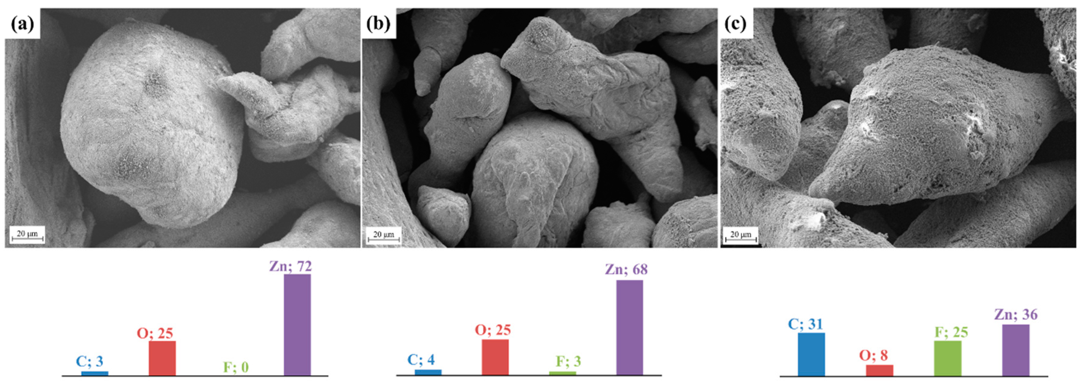
3.1. Coating of Zn Powder with Nafion® as the Protective Ionomer Layer

The surface micrographs of bare zinc powder and Nafion®-coated zinc particles (ICZP) are presented in Figure 1. As the ionomer content increases (from 1 wt. % in Figure 1b to 5 wt. % in Figure 1c), an apparent dark rough surface when compared to the clean surface of ICZP-0 (Figure 1a) appears. These dark areas have been associated to the deposition of the ionomer on the zinc surface. Therefore, EDS-mapping was performed in order to confirm the ionomer presence. The EDS results (included as colored bars in the corresponding samples in Figure 1) certificate the increase of fluorine and carbon, both associated to the increased content of Nafion®, which contains fluoro-carbon backbone (Nafion® molecular formula: C9HF17O5S). Moreover, this measurement also corroborates the steady decrease of zinc signal from ICZP-0 (72 wt. %) to ICZP-5 (36 wt. %) in those dark regions due to Nafion® coating on the zinc surface.
As observed in Figure 1c, the protective ionomer layer is apparently more uniformly distributed due to the higher Nafion® content (5 wt. % in ICZP-5). Hence, it is expected that this Nafion® layer spread on zinc particle surfaces would act as a barrier to reduce the diffusion of discharge products (i.e., zincate ions) to the bulk electrolyte. This would keep zincate ions in the proximity of the electrode surface, minimizing the dissolution of zinc (closely related to shape change and dendrite formation), and favoring zinc deposition during battery charging processes [28].
However, it is reasonable to foresee that this type of ionomer (cation exchange) layer reduces the diffusion of hydroxide ions (OH) from the electrolyte to the zinc surface. Some authors have determined the low transport of OH and minimal diffusion of zincate ions (D = 4 × 10⁻⁸ cm2 min−1) through the Nafion® membrane [39]. This fact supports our intention of reducing the loss of zinc by keeping it partially protected with the ionomer. Nevertheless, our approach presents an important difference: the zinc particles are partially coated with Nafion®, while the use of a membrane or modified/coated separator [3,39,40] placed between electrodes will cover the complete electrode surface.
In this context, a gradient of hydroxide and zincate ions concentration may occur at the boundaries of uncoated and coated regions. As will be demonstrated in Section 3.4, it will slightly impact the practical discharge capacity of the battery since localized ionomer-coated zinc would slow down its reactivity with hydroxide, owing to the lessened mobility of this anion across the ionomer layer (Nafion® has a OH transfer number of 0.14 [39]). However, as intended with this approach, its cycle life should be extended by limiting the full exposition of the zinc surface to the electrolyte over long-term cycling. On the other hand, the hydrogen evolution rate can be controlled by the water content in the near zinc surface. The latter might be somehow achieved by ionomer water/electrolyte uptake [41,42,43,44,45], or the reduced activity of water induced by the presence of fluoride and carbonate ions [9,46]. Side reactions, such as zinc corrosion, would be slowed down during charging.

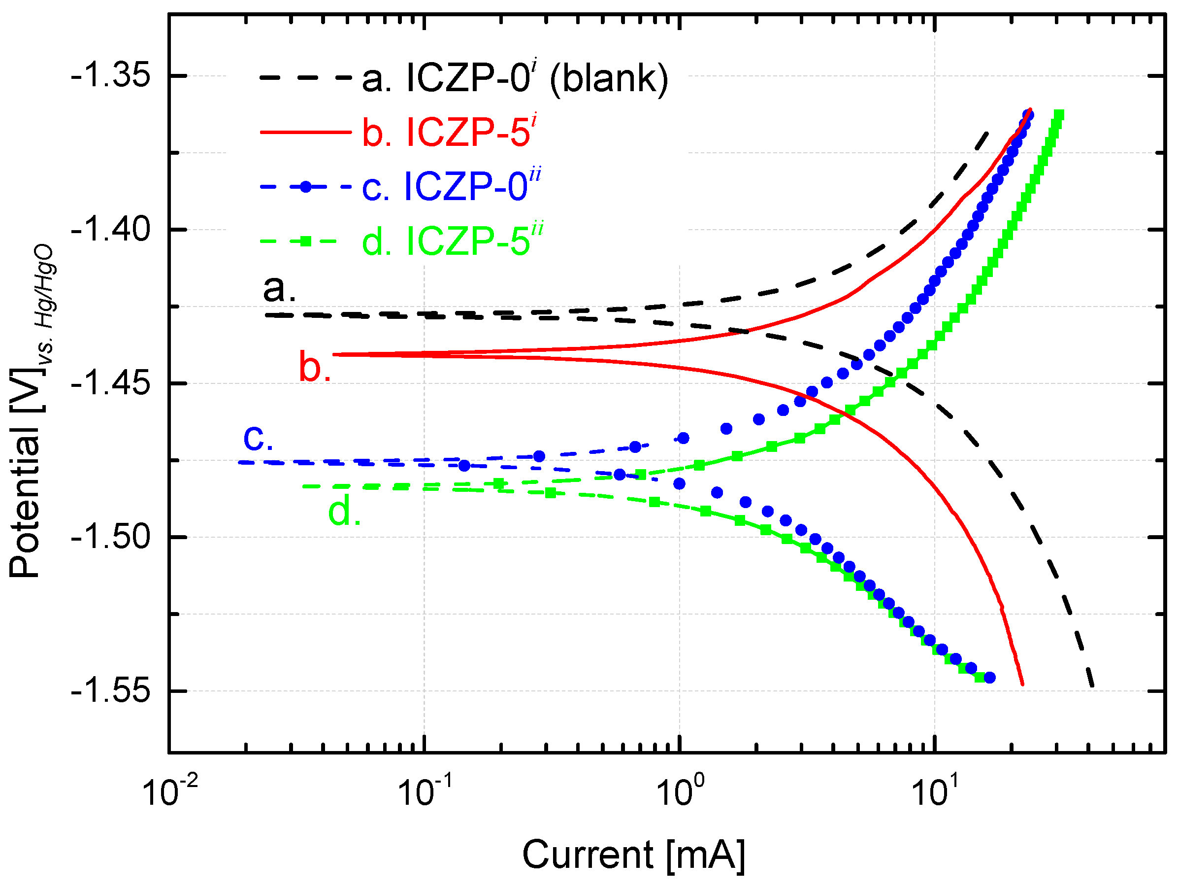
3.2. Polarization Behavior of Uncoated and Coated Zinc Particles

The polarization behaviors of ICZP-0 and ICZP-5 in aqueous alkaline electrolyte without (i: blank) and with additives (ii: 4s-2) are illustrated in Figure 2. The corrosion potential (Ecorr) and the corrosion current (icorr) are obtained by extrapolation of anodic and cathodic Tafel lines. Straightaway, the corrosion rate (CR) and the protective efficiency (Eff) of additives are determined and are listed in Table 2.
As shown in Figure 2 and summarized in Table 2, the blank (ICZP-0 in 6.6 M KOH) has an Ecorr of −1.427 VHg/HgO (1.329 V vs. SHE) in good agreement with the literature [19,47]. In this case, the redox potential of the pair Zn2+/Zn (E0 = −0.763 V vs. SHE) is negatively shifted because of higher pH, formation of ZnO (E0 for ZnO/Zn pair) and/or the formation of zincate (viz. Zincate/Zinc redox couple) [46] through coordination of Zn2+ with hydroxides ions. For the same electrolyte, the ionomer coating (curve b. in Figure 2) induces a slight negative shift (13 mV) of the corrosion potential (third column in Table 2). In this respect, the local ionomer coating may provoke an accumulation of zincate ions at the vicinity of the coated zinc surface [28], thus promoting the negative shift of the potential.
As the concentration of zincates increases (and/or OH ions decreases) in the zinc-surface/electrolyte interface, the redox potential becomes more negatives due to its dependence on the concentration of both ions. Thus, in the 4s-2 electrolyte, ICZP-0 (curve c. in Figure 2) shows an Ecorr of −1.476 VHg/HgO which is 49 mV more negative than that of the traditional electrolyte (curve a.). In the same 4s-2 electrolyte, the coated ICZP-5 sample (curve d.) has an Ecorr = −1.484 VHg/HgO. As observed, these results suggest that the electrolyte and electrode additives lead to a cathodic shift of the corrosion potential with respect to the blank electrolyte (curve a. in Figure 2), suggesting that zinc corrosion is mainly inhibited by suppressing the cathodic reaction, namely the hydrogen evolution reaction. This shift will also expand the electrochemical stability window of the aqueous electrolyte [9].
Nevertheless, in comparison to the blank electrolyte, the corrosion current (icorr) and the cathodic current (Figure 2) are lower for all the systems containing additives (electrolyte and/or electrode). This trend supports the fact that, in alkaline media, the presence of zincate ions lowers the activity of water and it hence reduces the hydrogen evolution rate. Therefore, as mentioned above, joint additives (electrolyte + electrode) could be considered as a cathodic inhibitor. In this process, the Nafion® coating plays the role of mitigating the corrosion by locally preserving a high concentration of zincate ions, which cannot easily diffuse into the bulk electrolyte. Consequently, the corrosion rate (CR) of the zinc electrode decreased from 10.4 (blank) to 1.3 mgZn cm−1·s−1 (ICZP-5ii), due to the beneficial synergistic effect of combining electrolyte and electrode additives.
All in all, this strategy (combining electrolyte and electrode additives) provides a beneficial joint protective efficiency of 87%. Even so, the Ecorr for sample ICZP-5 in 4s-2 electrolyte presents a cathodic shift (57 mV) in comparison to the blank ICZP-0 in 6.6 M KOH. From a technical point of view, this issue can be controlled by properly setting a cut-off voltage [34]. Nevertheless, for long-term battery cycle life, the water depletion, ZnO formation, and variation of OH concentration may lead to an increase of cell internal resistance, thus affecting the cell voltage.
On the other hand, to determine the effectiveness of the Nafion® coating on mitigating the zinc redistribution (shape change or dendrite growth), a potentiostatic polarization (−200 mV with respect to OCV) was applied to the uncoated and coated samples in modified aqueous alkaline electrolyte (4s-2). Figure 3 shows the FE-SEM images of zinc pellets that are composed of uncoated (ICZP-0) and coated (ICZP-1 and ICZP-5) zinc particles. A clear formation of dendrites is noticed for ICZP-0 (Figure 3a) in comparison to ICZP-1 (Figure 3b) and ICZP-5 (Figure 3c). Inserted magnified micrographs show, without any doubt, how effectively the presence of ionomers mitigates the dendrite growth until the point at which they are avoided, as shown by the ICZP-5 sample. The uniform electrode surface that was observed in the ICZP-5 sample can be associated to the better spread of the Nafion® coating. This minimizes the uneven distribution of zincate ions in the electrode surface/electrolyte interface, allowing for a homogeneous zinc deposition at the applied cathodic polarization.
This preliminary characterization shows that coating zinc particles with Nafion® in conjunction with implementing electrolyte additives could be an effective strategy to mitigate the corrosion of zinc (via low HER rate), minimize the shape change and the formation of dendrites, and hence promote an extended battery cycle life. In order to explore the latter, and before testing this approach in a zinc–air battery, the cycle life of ionomer-coated zinc particles in 4s-2 electrolyte is initially investigated by cyclic voltammetry in a symmetric Zn/Zn cell, as shown in the following section.

3.3. Cyclic Voltammetry and Reversibility of Zn Electrodes

In order to minimize the dissolution of discharge products from the zinc electrode into the bulk electrolyte and hence decrease the shape change and dendrite formation, a combined strategy, including electrolyte and electrode additives, is implemented. This approach was initially investigated with a compressed dried uncoated (ICZP-0) and ionomer-coated Zn (ICZP-1; ICZP-5) battery grade powder (pellets) and then validated with more realistic electrodes made of a zinc paste containing electrolyte and binder. All of the characterizations were performed with 4s-2 electrolyte, since it will be difficult to compare peak currents between electrolytes with different ionic conductivities (IC) due to the fact that less conductive solutions may induce lower currents.

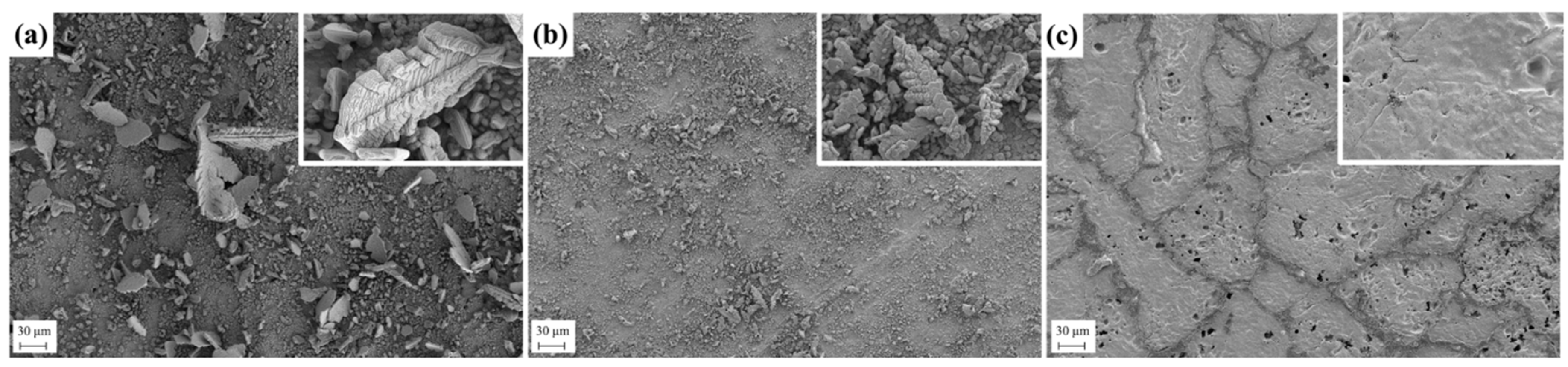
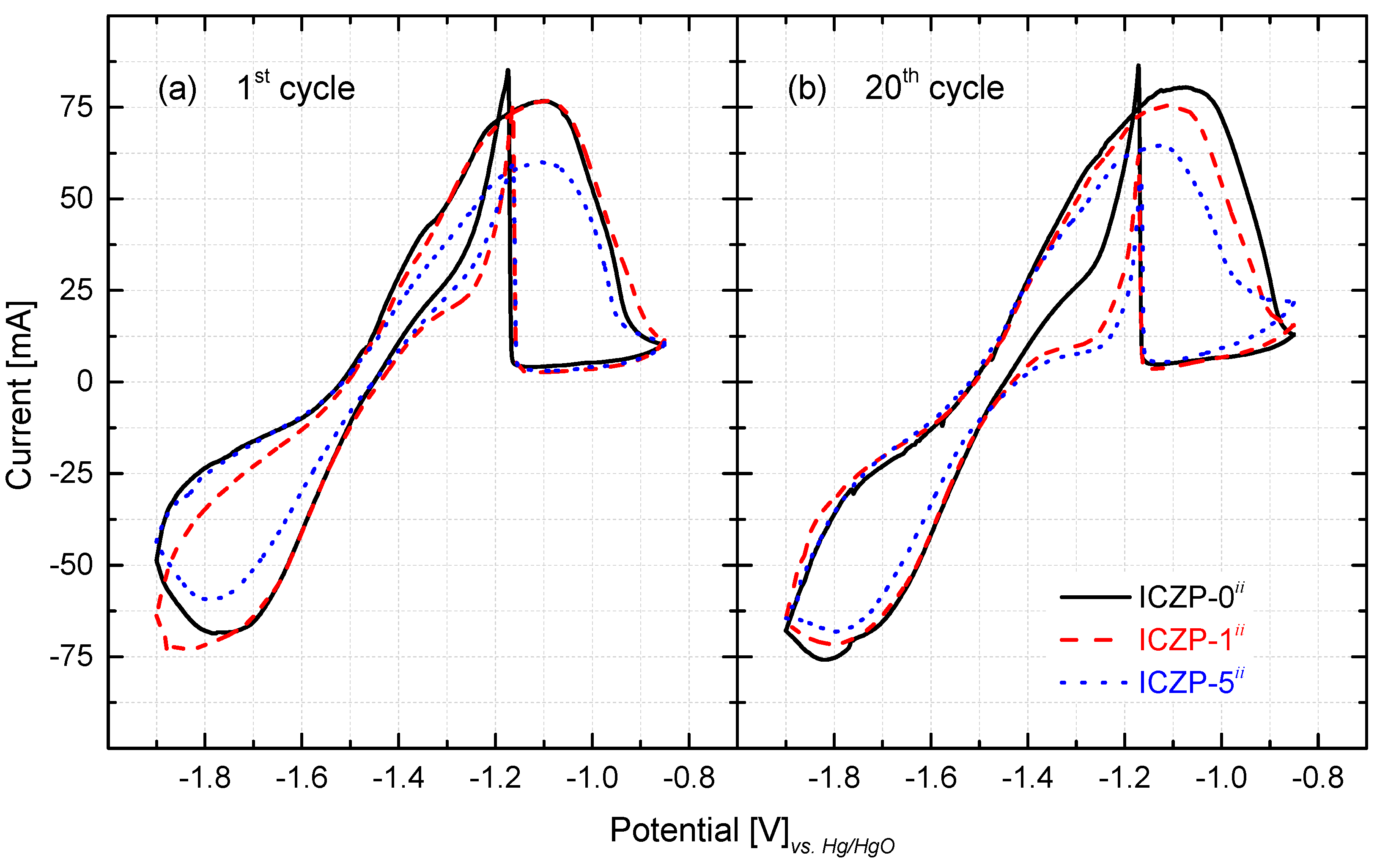
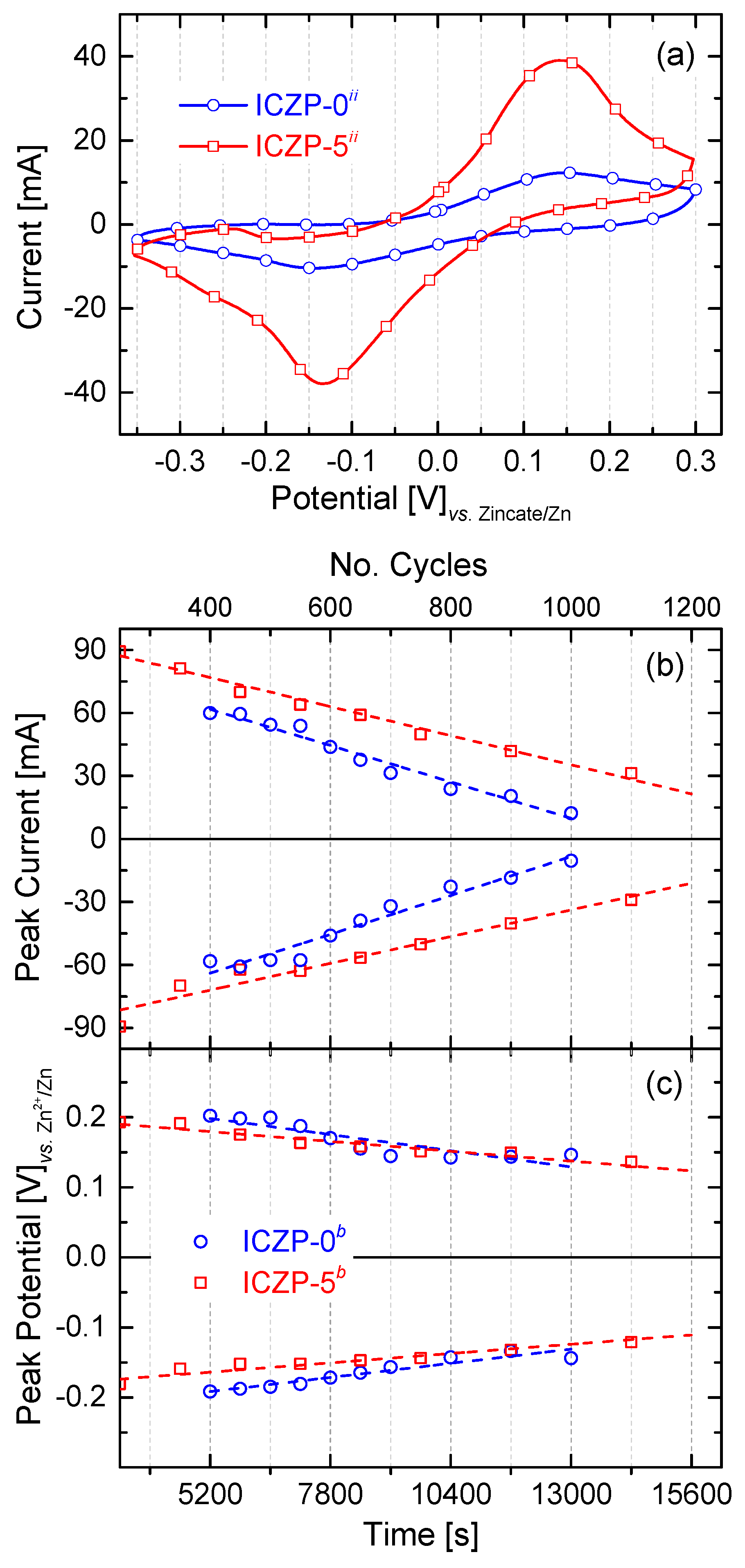
3.3.1. Zn-Pellet Electrodes

The cyclic voltammogram (CV) characteristics for the three zinc-pellet electrodes in aqueous alkaline 4s-2 electrolyte are presented in Figure 4. As observed, in the positive-going scan (10 mV s−1), an anodic current peak appears in the voltage range compressed between −1.2 and −1.0 V (vs. Hg/HgO) for all three samples at the first (Figure 4a) and at the 20th cycle (Figure 4b). This broad peak is assigned to the electrochemical oxidation of Zn to form a zincate complex (viz. Zn + 4OH ↔ Zn(OH)42− + 2e). As soon as the zincate ion reaches its solubility limit in the electrolyte, precipitation of porous ZnO takes place (viz. Zn(OH)42− ↔ 4ZnO(s) + H2O + 2OH). The latter slows down the further oxidation of Zn due to the depletion (diffusion limitation by the formed ZnO layer) of OH at the electrode/electrolyte interface. Gradually, a ZnO layer is formed on the Zn electrode surface, and hence, as soon as a thick layer is formed, the current decreases sharply due to the passivation of the Zn electrode surface.
During the negative-going sweep, a sharp peak is observed (close to −1.2 V). As reported elsewhere [19,48], this peak is assigned to the re-establishment of the zinc oxidation process after breakage (partial removal) of the ZnO passive film (viz. ZnO(s) + H2O + 2OH → Zn(OH)42−) [49,50]. Subsequently, a less defined peak cathodic current emerges in the potential region from −1.7 to −1.9 V (vs. Hg/HgO). This is related to the reduction of the accumulated ZnO that remains on the electrode surface, which is not dissolved into the electrolyte [27,51,52], as well the reduction of the zincate ion to Zn metal (viz. Zn(OH)42− + 2e → Zn(s) + 4OH). Both of these processes seem to hinder the H2 evolution current that apparently does not contribute to the CV characteristics [34]. Furthermore, the presence of zincate ions, as well as of the given concentration (2 mol L−1) of additives KF and K2CO3 promotes a delay in the HER onset or hinders its contribution (neglected current) [9].
It is noteworthy that, as the ionomer content increases (from 1 to 5 wt. %), the cathodic/anodic current peak decreases in comparison to the ionomer-free ICZP-0 sample (Figure 4). In that sense, as the capacity value is proportional to the peak area (charge, q), it can be assumed that the coated zinc sample would have lower capacity in comparison to the uncoated sample. In fact, at the 20th cycle, the ICZP-0 sample presented an anodic charge (qA) of 3.29 C, while ICZP-1 and ICZP-5 have charges of 3.14 C and 2.96 C, respectively. This characteristic can be associated to a less active Zn surface that was directly exposed to the electrolyte and/or due to a lower concentration of OH at the electrode/electrolyte interface [34] due to the presence of Nafion®. The latter is most likely due to the barrier effect of the ionomer, which may induce concentration gradients at the interface. After 20 cycles, the CV characteristics remain similar for all samples but with slight changes in the peak currents and positions. These changes might be assigned to the variation of OH concentration, the water depletion (viz. less activity) and/or irreversible ZnO formation (passivation) at the interface [19].
From the CV’s features, the anodic and cathodic peak potentials (EA and EC) and currents (iA and iC) can be determined (Table 2). This information provides a preliminary idea about the effect of the ionomer coating on the reversibility of the redox reaction pair Zn(OH)42−/Zn. As is known, the separation between the two peak potentials (∆Ep) can be used to define the electrochemical reversibility of a redox couple, with 0.058 n−1 (where ‘n’ denotes the number of electrons) being the value for an electrochemical reversible case [53]. From Figure 4 and Table 2 (sixth and seventh column), it is very clear that it is not the case for the current redox reaction. Thus, in this case, reversibility retention might be better associated to the preservation of the anodic and cathodic charge (Coulombic efficiency). This reversibility could also be assessed by the relative ratio of the reduction peak current to its paired oxidation peak current (iC/iA), which, in the case of being equal to one, can be interpreted as a fully reversible system [53].
As observed in Table 2, after 20 cycles, ∆Ep increases, whereas the reduction current ratio (iC/iA) decreases for the ICZP-0 and ICZP-1 samples. In contrast, (∆Ep) and (iC/iA) decrease and increase, respectively, for the ICZP-5 sample. This trend indicates that for ICZP-0 and ICZP-1 the equilibrium at the surface is no longer swiftly established, so the anodic reaction becomes dominant over cycling, while for the ICZP-5 Zn sample, recovery can be effectively improved during reduction. With these preliminary results, it can be assumed that the strategy of combining electrolyte and electrode additives may favor the reversibility, and hence, coating zinc particles with Nafion® effectively delays the zinc dissolution into the electrolyte by means of creating a reservoir of zincate in the electrode/electrolyte interface [28]. The latter induces a homogeneous deposition of Zn (Figure 3c) and it may promote an extended cycle life of more realistic zinc-paste electrodes.

3.3.2. Zn-Paste Electrodes

In order to assess the long-term effectivity of this approach, realistic Zn-paste electrodes were prepared based on uncoated (ICZP-0) and 5 wt. % Nafion®-coated (ICZP-5) Zn particles. The samples were extensively cycled (5 mV s−1 between −0.3 V and 0.30 V vs. Zn2+/Zn) in 4s-2 electrolyte while using a symmetric (Zn/Zn) homemade cell.
Similar to what was performed with Zn-pellet electrodes, cyclic voltammetry was initially carried out in order to determine the reversibility of realistic Zn electrodes before implementing it into a full cell. Samples were cycled until typical zinc CV features (anodic and cathodic peaks) were not more appreciable. As shown in Figure 5a, there is a clear enhancement of the electrode cycle life when Zn particles are coated with the ionomer. Whereas, uncoated ICZP-0 samples could not be cycled beyond 1000 times, the coated ICZP-5 samples reached over 1200 cycles. However, both samples had a progressive loss of active material, as shown by the lower CV currents during cycling.
In that respect, Figure 5b illustrates the gradual decrease of cathodic and anodic peak currents during cycling (over time). Whereas, ICZP-0 has a slope (degradation rate) of 71.3 × 10⁻⁴ and 66.6 × 10⁻⁴ mA s−1 for the cathodic and anodic processes, respectively, ICZP-5 shows a slowdown of both the cathodic and anodic reactions (i.e., 48.9 × 10⁻⁴ and 53.2 × 10⁻⁴ mA s−1, respectively) in comparison with ICZP-0. The slopes, as shown in Figure 5b for the ionomer-free sample ICZP-0, indicate that the anodic processes are becoming dominant (lower slope) over the cathodic ones. This behaviour indicates that the ICZP-0 sample still presents anodic limitations such as metal dissolution, passive layer formation, etc., although an advanced electrolyte based on additives is used. However, the opposite trend is observed for the ionomer-coated sample ICZP-5 where the cathodic (reduction) reactions are slightly dominant, thus the recovery of Zn is favorable. This allows for the Zn-coated sample to extend its cycle life by about 20% in comparison to the uncoated zinc particle. These results confirm the additional protection efficiency (Table 2) of the ionomer coating. Both of the samples have shown a similar trend with respect to the cathodic and anodic peak potentials and their differences (∆Ep), as illustrated in Figure 5c.
Analyzing further the data provides for the extended cycling test (Figure 5), which enables the capacity retention and the coulombic efficiency to be calculated. The capacity retention is considered the relation between the initial capacity of the reference cycle and the capacity of the cycle to be evaluated. Thus, for this analysis, the initial capacity has been selected for the 100th cycle in order to secure a full activation of the Zn-paste electrodes. On the other hand, the Coulombic efficiency is the relation between the charge and discharge capacities at the same cycle, which provides information about the reversibility of the electrochemical reactions, similar to the function of the ratio (iC/iA). A low Coulombic efficiency will mean the presence of irreversible reactions.
In this context, the reversibility (Coulombic efficiency) of both electrodes is high (close to 100% over the entire cycle life). However, the principal difference between them is observed in the capacity retention. As is known, the loss of the capacity retention can be related with degradation phenomena, such as the passivation of active surface sites or the loss of active material itself. Thus, a loss of 20% of the initial capacity is reached by ICZP-0 samples after 400 CV cycles, while ICZP-5 needed over 500 CV cycles to have the same capacity loss. Cycling of ICZP-0 was stopped when the sample lost 80% of its initial capacity (after 1000 CV cycles). At that CV cycle number, ICZP-5 presented a 50% loss of its initial capacity. With these enhanced results, the strategy of using ionomers as the protective layer is again confirmed, since it will diminish the dendrite formation, mitigate anode shape changes, slow down the corrosion (diffusion) rate, and will minimize the loss of active material over the long-term cycle life.
All in all, these results validate the favorable combination of simultaneously using electrolyte and electrode additives to enhance the cycle life of a Zn electrode for secondary battery applications. In this sense, in the next section, a lab-scale homemade Zn–air battery (2.5 cm2 active site) is used to assess this approach under more realistic battery operating conditions.

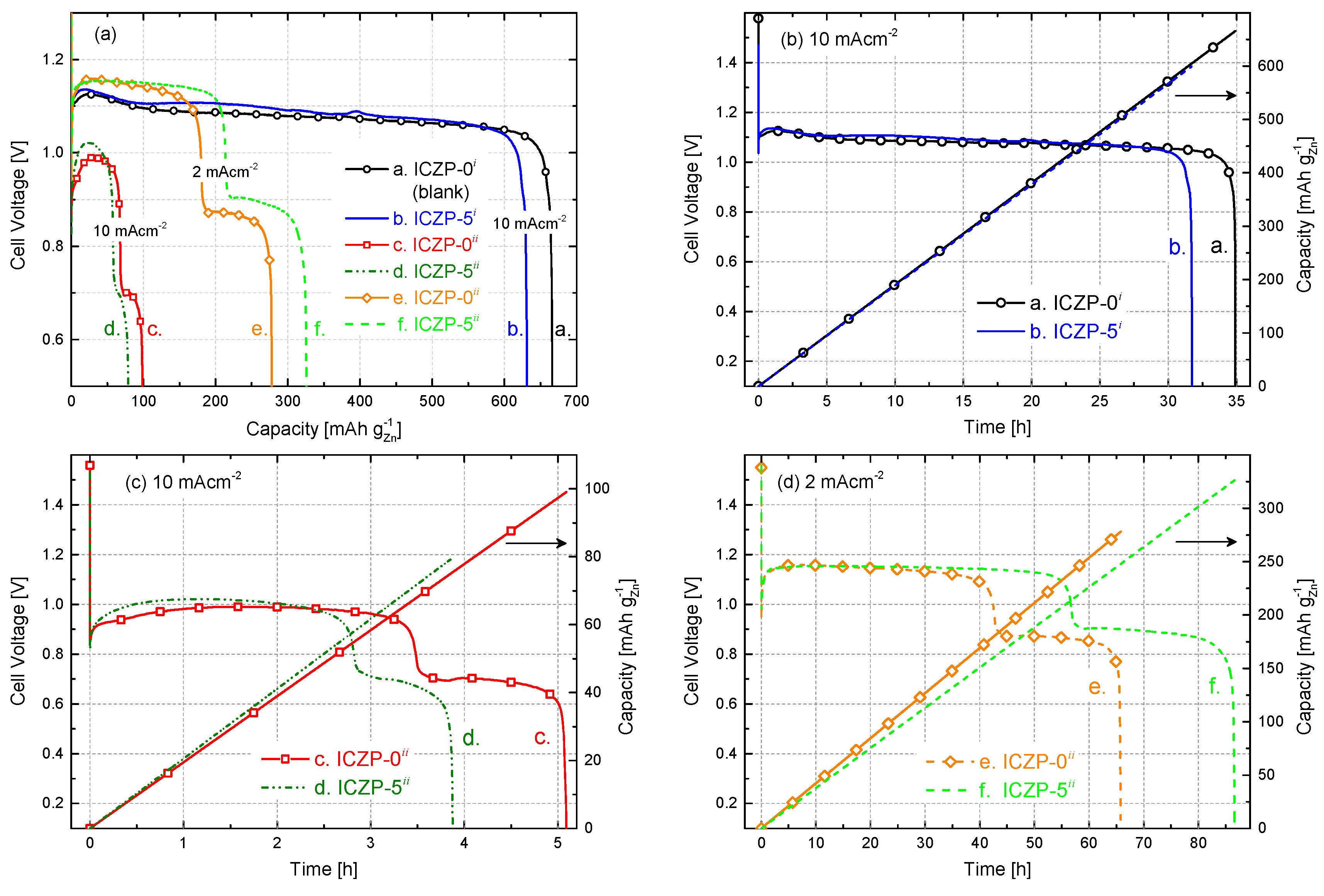
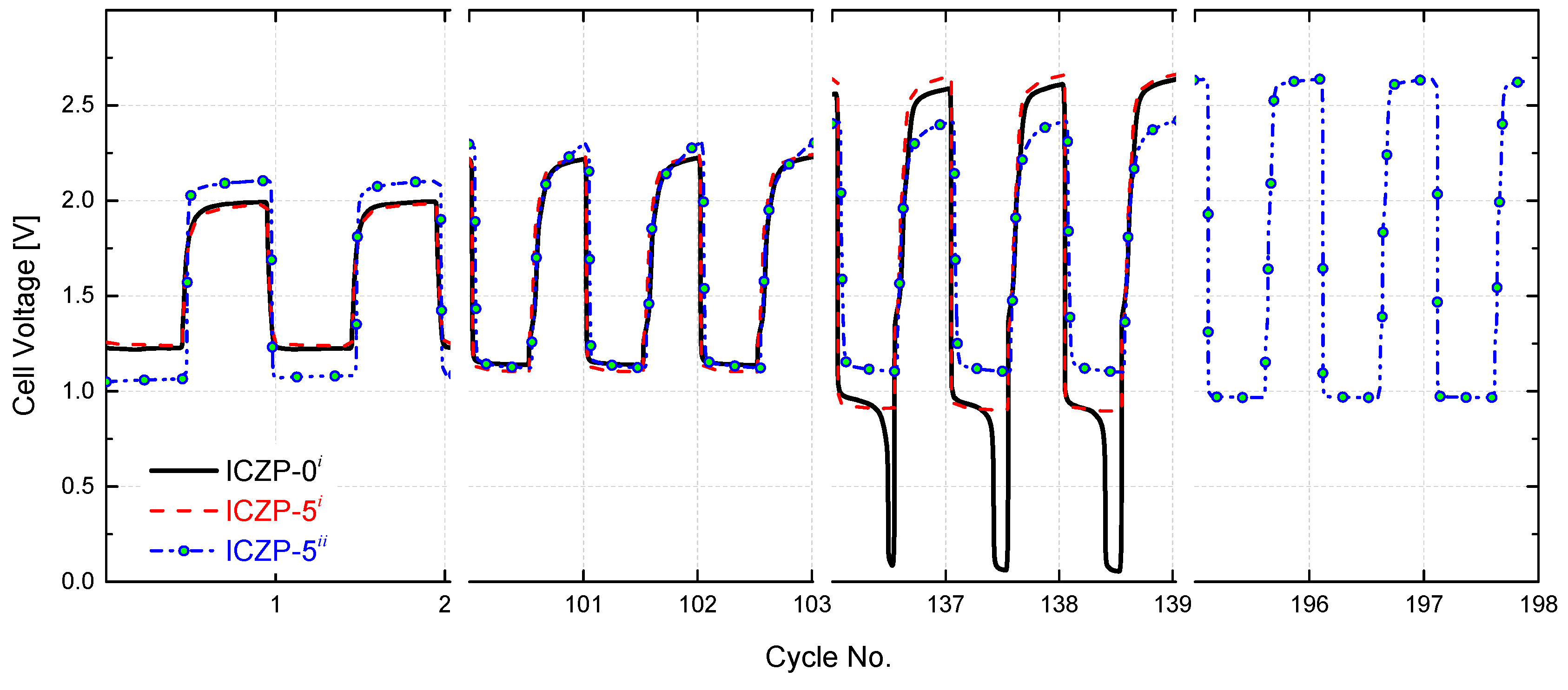
3.4. Full Cell Cycle Life Assessment under Closer Battery Operating Conditions

Galvanostatic discharge curves of uncoated (ICZP-0) and ionomer-coated (ICZP-5) Zn particles in 6.6 M KOH (i: blank) and modified (ii: 4s-2) aqueous alkaline electrolyte at two current densities are displayed in Figure 6a. Figure 6b shows the ionomer coating effect in the blank electrolyte system. As observed, for the ICZP-0i sample (curve a.), the practical specific capacity was 666 mAh g Z n 1 , which represents an active material utilization of 81.2% according to the theoretical zinc-specific capacity (820 mAh g Z n 1 ). In contrast, ICZP-5 delivered a practical specific capacity of 631 mAh g Z n 1 (77% active material utilization) in blank electrolyte. In this context, the material utilization of uncoated zinc particles (ICZP-0) is 5% higher than that for ionomer-coated zinc particles (ICZP-5) at 10 mA cm−2. This difference can be attributed to the zinc metal exposed to the aqueous electrolyte that is partially inhibited by the ionomer coating as mentioned above.
In contrast, when both samples are discharged in 4s-2 electrolyte (ii) at the same applied current density (Figure 6c), the active material utilization dropped to 12% (98.5 mAh g Z n 1 ) and 10% (79.2 mAh g Z n 1 ) for ICZP-0ii (curve c.) and ICZP-5ii (curve d.), respectively. This means a reduction in the active material utilization of around 85–88% in comparison to the discharge curves in blank electrolyte (curve a. in Figure 6b).
This drastic decrease in active material utilization can be initially attributed to both the lower ionic conductivity and KOH concentration (where Zn is less soluble) of 4s-2 electrolyte in comparison to the blank electrolyte. Moreover, in 4s-2, a faster passivation process might occur, as indicated by the discharging time (Figure 6c vs. Figure 6b) limiting the zinc utilization. One reason for that is the initial zincate concentration (from ZnO-saturated electrolyte) near the electrode surface. As proposed by J. Stamm et al. [37], this will induce a faster nucleation of ZnO, and hence precipitation occurs due to the supercritical concentration being swiftly reached. The latter is also accelerated by the applied current density (Figure 6c vs. Figure 6d). In that way, the presence of zincate shortens the passivation time and promotes the precipitation of so-called Type I ZnO (in principle, a porous film which allows, to a lesser extent, the diffusion of ions to/from the electrode surface).
All of the discharge profiles exhibit an initial drop in cell voltage, followed by a pronounced increase at the beginning of discharge processes. The voltage dip right after OCV is explained by J. Stamm et al. [37] as a consequence of the slow oxygen reduction and a faster nucleation and precipitation of ZnO. The latter is induced by an initial increment of zincate concentration and a simultaneous decrease of the hydroxide concentration. In the following, the cell voltage recovers because of the increasing surface area for precipitation, which induces a decrease of zincate and an increase of hydroxide concentrations. The same authors pointed out that the cell voltage step (200 mV cell voltage loss between 2 and 4 h observed in Figure 6c) can be assigned to the swift change from the oxidation of the uncovered to ZnO-covered Zn surface where the Zn underneath the formed ZnO layer takes over the oxidation process [37,54]. As soon as this ZnO film becomes sufficiently thick and compact, it blocks the migration of hydroxide ions to the electrode surfaces and impedes the diffusion away from zincate and water (similar to what is assumed to be done by the ionomer layer). This condition will then promote the formation of an irreversible Type II ZnO passivation layer [55,56,57], and hence a sudden drop of the cell voltage is observed. As shown in Figure 6c, this cell voltage drop occurs earlier on ICZP-5 (curve d.) than ICZP-0 (curve c.). It is assumed that, similar to both types of ZnO layers, the ionomer coating contributes to the mass transfer limitations, hampering the further Zn dissolution.
Despite the fact that the addition of specific additives, such as ZnO, KF, and K2CO3 to the electrolyte help to lessen Zn corrosion (Table 2), dendrite formation, shape change, etc., they could have a negative impact on the resulting nominal capacity (Figure 6) if the electrolyte/additive concentrations and battery operating conditions are not determined and optimized [9]. The main reason for those unfavorable effects is the consumption of hydroxide and water, i.e., decrease of the ionic conductivity and increase of viscosity promoted by the additives [9,14,37]. For example, the addition of KF removes water by hydration and this loss of water lowers the mobility of OH ([58] and refs. therein); however, such a process will also decrease the corrosion rate of Zn, enhancing its resistance towards self-discharge. Therefore, a balance among base electrolyte, additives, and battery performance must be found [9].
Figure 6d illustrates how the cell practical capacity in 4s-2 electrolyte (ii) can be increased by adjusting the applied current density. When current density was decreased five times (from 10 to 2 mA cm−2), the capacity of the ICZP-0 sample (curve e.) increased from 98.5 to 277.6 mAh g Z n 1 (i.e., 2.8-times), while for the coated ICZP-5 sample (curve f.), the increment was four times higher (from 79.2 to 325.8 mAh g Z n 1 ) extending 17 times the discharging time of the battery (Figure 6c vs. Figure 6d). Of note, the discharge features in Figure 6d are similar to those in Figure 6c, indicating that the reaction mechanisms and transport processes are still the same but at a lower rate. Nevertheless, a lower current density also induces lower overpotentials, and hence, a higher constant flat discharge voltage can be obtained (Figure 6), although delivered power/energy might be less in this case.
In order to assess the effect of combining the benefits of electrolyte and electrode additives on the cycle life of a homemade ZAB, the uncoated ICZP-0 and ionomer-coated ICZP-5 samples were cycled at 5 mA cm−2 (discharging time, td, and charging time, tc, set each at 10 min) in the blank and 4s-2 electrolytes up to the discharge voltage drop-off, below the reference (not set) cut-off voltage (0.95 V). Figure 7 displays the cell voltage profiles for the tested samples. As shown over 100 cycles, the use of Nafion® as a protective ionomer coating layer in ICZP-5i does not alter the cell voltage features in comparison to ICZP-0i in blank electrolyte. In this electrolyte, the battery using ICZP-0 performed 135 cycles smoothly before the discharge voltage fell steadily beyond 0.95 V. Although the ICZP-5 sample did not significantly extend the cycle life (140 cycles) in that electrolyte, the voltage drop was gradual and less sudden. Nevertheless, when ICZP-5 was cycled in 4s-2 electrolyte, the battery achieved 198 cycles (intentionally stopped) with an end-of-test discharge voltage of 0.97 V. This result represents a ca. 1.5-times enhancement of the cycle life of the zinc–air battery by implementing a joint mitigation strategy by means of electrolyte additives and ionomer-coated zinc particles.
Furthermore, the extended accelerated cycling shows that coating the Zn particle with an ionomer promotes better battery roundtrip efficiency in comparison to the uncoated samples by regulating the exposition of zinc to the electrolyte during the cycling. That efficiency is improved when, in addition to the protective ionomer layer, additives in the electrolyte are used. Thus, the sample ICZP-5 cycle in 4s-2 electrolyte initially provides a battery roundtrip-efficiency of 50% (lower in comparison to the same sample in blank electrolyte, but preserved over 100 cycles), which decreases to 37% after 198 cycles, while ICZP-5 in the blank electrolyte showed 64% roundtrip efficiency at the first cycle that decreased to 50% after 100 cycles and then to 34% after 140 cycles. The worst result was obtained by uncoated ICZP-0 in blank electrolyte. This sample lost almost all of its initial roundtrip efficiency (62%) due to the significant discharge voltage drop-off associated, in principle, to the passivation process, and hence limited mass transport rate over cycling.
This accelerated test confirms the benefits of extending the ZAB cycle life by combining mitigation strategies in one joint approach by using additives in the base electrolyte and simultaneously preparing electrodes that are based on ionomer-coated zinc particles [9,28].
As a next step to approach more realistic cell operating conditions, and, based on the practical capacity value (~350 mAh) that was obtained at the cut-off voltage of 1.0 V for sample ICZP-5 in 4s-2 electrolyte (Figure 6d, curve f.), the homemade secondary zinc–air battery was cycled at 1 mA cm−2, demanding 35 mAh (td = 13.5 h) and storing the same capacity (tc = 13.5 h).
As displayed in Figure 8, the cell was based on ionomer-coated ICZP-5 and 4s-2 electrolyte. The battery lasted over 300 h (10 cycles) before the charging voltage increased suddenly due to electrolyte dry-out in our non-optimized homemade cell design. Nevertheless, this cell initially presented a battery roundtrip-efficiency of 59% with an overvoltage (ΔV = VOER − VORR) of 0.82 V. After 10 cycles (270 h), the battery round-efficiency decreased to 55%. This loss was associated to an increment of 100 mV in the charging voltage (limited OER kinetics and/or promotion of HER) and to a decrease of 30 mV at the discharging voltage (most likely due to ohmic and mass transport losses). In any case, the homemade lab-scale zinc-air cell was able to deliver a specific energy density of 25 Wh k g Z n 1 ten times. However, the cell design and electrolyte formulation should be optimized in order to further improve the battery performance.

4. Conclusions

An alternative procedure to enhance the cycle life of a rechargeable zinc–air battery (ZAB) has been presented. By combining mitigation strategies in one joint approach, zinc electrodes that are based on ionomer (Nafion®)-coated zinc particles were manufactured and the cycle life was assessed in a base electrolyte (KOH) modified with ZnO, KF and K2CO3 as additives (in this work, ZnO-saturated 4 M KOH + 2 M KF + 2 M K2CO3). The joint use of electrolyte additives and ionomer coating was intended to deal with zincate solubility, to minimize shape change and dendrite formation, as well as to reduce the HER.
In this process, Nafion® ionomer mitigated the corrosion by locally preserving a high concentration of zincate ions (also lowering the water activity and hence altering the HER rate), which cannot easily diffuse into the bulk electrolyte. Consequently, the corrosion rate (CR) of the zinc electrode decreased from 10.4 to 1.3 mgZn cm−1·s−1 (coated Zn in 4s-2 electrolyte). That means an overall protective efficiency of 87%. The reduction of the dissolution rate was associated to the formation of domains with an even distribution of zincate ions in the electrode surface/ionomer/electrolyte interface. The latter allowed for a homogeneous zinc deposition, mitigating the shape change and dendrite formation.
All in all, although the rate capability and capacity are limited, with this approach, ionomer-coated Zn particles extended the ZAB cycle life by about 50% in shallow cycling as compared to uncoated zinc particles in additive-free KOH. The homemade lab-scale secondary zinc-air cell was then able to deliver ten times a stable (13 h) specific energy density of 25 Wh k g Z n 1 , in spite of the fact that the battery roundtrip efficiency decreased from 59% to 55% after 270 h of operation. Nevertheless, high-performing Nafion®-coated zinc particles, as electrode material for secondary zinc-based energy storage systems in the modified base electrolyte, have been obtained.

Author Contributions

Conceptualization, A.R.M. and J.A.B.; A.R.M. performed the experiments; A.R.M. and L.C.C. analyzed the data and wrote the paper; H.-J.G. and J.A.B. provided guidance. All authors discussed the data.

Funding

This research was funded by the University of the Basque Country under the program ZABALDUZ2012; the European Commission through the project ZAS: “Zinc Air Secondary innovative nanotech based batteries for efficient energy storage” (grant number 646186) and by the Basque Government through the program ELKARTEK 2016.

Conflicts of Interest

The authors declare no conflict of interest.

References

  1. Pei, P.; Wang, K.; Ma, Z. Technologies for extending zinc–air battery’s cyclelife: A review. Appl. Energy 2014, 128, 315–324. [Google Scholar] [CrossRef]
  2. Zhu, L.; Zhang, H.; Li, W.; Liu, H. New modification procedure of zinc powder in neodymium nitrate solution for improving the electrochemical properties of alkaline zinc electrodes. J. Phys. Chem. Solids 2009, 70, 45–54. [Google Scholar] [CrossRef]
  3. Vatsalarani, J.; Trivedi, D.C.; Ragavendran, K.; Warrier, P.C. Effect of Polyaniline Coating on “Shape Change” Phenomenon of Porous Zinc Electrode. J. Electrochem. Soc. 2005, 152, A1974–A1978. [Google Scholar] [CrossRef]
  4. Devyatkina, T.I.; Gunko, Y.L.; Mikhalenko, M.G. Development of Ways to Diminish Corrosion of Zinc Electrode. Russ. J. Appl. Chem. 2001, 74, 1122–1125. [Google Scholar] [CrossRef]
  5. Banik, S.J.; Akolkar, R. Suppressing Dendritic Growth during Alkaline Zinc Electrodeposition using Polyethylenimine Additive. Electrochim. Acta 2014, 179, 475–781. [Google Scholar] [CrossRef]
  6. Li, Y.; Dai, H. Recent advances in zinc-air batteries. Chem. Soc. Rev. 2014, 43, 5257–5275. [Google Scholar] [CrossRef] [PubMed]
  7. Yu, J.; Yang, H.; Ai, X.; Zhu, X. A study of calcium zincate as negative electrode materials for secondary batteries. J. Power Sources 2001, 103, 93–97. [Google Scholar] [CrossRef]
  8. Jo, Y.N.; Kang, S.H.; Prasanna, K.; Eom, S.W.; Lee, C.W. Shield effect of polyaniline between zinc active material and aqueous electrolyte in zinc-air batteries. Appl. Surf. Sci. 2017, 422, 406–412. [Google Scholar] [CrossRef]
  9. Mainar, A.R.; Iruin, E.; Colmenares, L.C.; Blázquez, J.A.; Grande, H.-J. Systematic cycle life assessment of a secondary zinc–air battery as a function of the alkaline electrolyte composition. Energy Sci. Eng. 2018, 6, 174–186. [Google Scholar] [CrossRef]
  10. Mainar, A.R.; Colmenares, L.C.; Blázquez, J.A.; Urdampilleta, I. A brief overview of secondary zinc anode development: The key of improving zinc-based energy storage systems. Int. J. Energy Res. 2017, 42, 903–918. [Google Scholar] [CrossRef]
  11. Mainar, A.R.; Leonet, O.; Bengoechea, M.; Boyano, I.; de Meatza, I.; Kvasha, A.; Guerfi, A.; Blázquez, J.A. Alkaline aqueous electrolytes for secondary zinc–air batteries: An overview. Int. J. Energy Res. 2016, 40, 1032–1049. [Google Scholar] [CrossRef]
  12. Bass, K.; Wicox, P.J.; Smith, J. Methods for the reduction of shape change and dendritic growth in zinc-based secondary cells. J. Power Sources 1991, 35, 333–351. [Google Scholar] [CrossRef]
  13. Adler, T.C.; McLarnon, F.R.; Cairns, E.J. Investigations of a New Family of Alkaline-Fluoride-Carbonate Electrolytes for Zinc/Nickel Oxide Cells. Ind. Eng. Chem. Res. 1998, 37, 3237–3241. [Google Scholar] [CrossRef]
  14. Sato, Y.; Niki, H.; Takamura, T. Effects of Carbonate on the Anodic Dissolution and the Passivation of Zinc Electrode in Concentrated Solution of Potassium Hydroxide. J. Electrochem. Soc. 1971, 118, 1269–1272. [Google Scholar] [CrossRef]
  15. Adler, T.C.; McLarnon, F.R.; Cairns, E.J. Low-Zinc-Solubility Electrolytes for Use in Zinc/Nickel Oxide Cells. J. Electrochem. Soc. 1993, 140, 289–294. [Google Scholar] [CrossRef]
  16. Parker, J.F.; Pala, I.R.; Chervin, C.N.; Long, J.W.; Rolison, D.R. Minimizing Shape Change at Zn Sponge Anodes in Rechargeable Ni–Zn Cells: Impact of Electrolyte Formulation. J. Electrochem. Soc. 2016, 163, A351–A355. [Google Scholar] [CrossRef]
  17. Thornton, R.F.; Carlson, E.J. Properties of Alternate Electrolytes for Secondary Zinc Batteries. J. Electrochem. Soc. 1980, 127, 1448–1452. [Google Scholar] [CrossRef]
  18. Jorné, J.; Adler, T.C.; Cairns, E.J. Visual Observations of Early Shape Changes in a Zinc/Nickel Oxide Cell. J. Electrochem. Soc. 1995, 142, 771–774. [Google Scholar] [CrossRef]
  19. Shivkumar, R.; Kalaignan, G.P.; Vasudevan, T. Effect of additives on zinc electrodes in alkaline battery systems. J. Power Sources 1995, 55, 53–62. [Google Scholar] [CrossRef]
  20. Hilder, M.; Winther-Jensen, B.; Clark, N.B. The effect of binder and electrolyte on the performance of thin zinc-air battery. Electrochim. Acta 2012, 69, 308–314. [Google Scholar] [CrossRef]
  21. Jain, R.; Adler, T.C.; McLarnon, F.R.; Cairns, E.J. Development of long-lived high-performance zinc-calcium/nickel oxide cells. J. Appl. Electrochem. 1992, 22, 1039–1048. [Google Scholar] [CrossRef]
  22. Luo, Z.; Sang, S.; Wu, Q.; Liu, S. A Conductive Additive for Zn Electrodes in Secondary Ni/Zn Batteries: The Magneli Phase Titanium Sub-Oxides Conductive Ceramic TinO2n−1. ECS Electrochem. Lett. 2013, 2, A21–A24. [Google Scholar] [CrossRef]
  23. Vatsalarani, J.; Geetha, S.; Trivedi, D.C.; Warrier, P.C. Stabilization of zinc electrodes with a conducting polymer. J. Power Sources 2006, 158, 1484–1489. [Google Scholar] [CrossRef]
  24. Zhu, J.; Zhou, Y. Effects of ionomer films on secondary alkaline zinc electrodes. J. Power Sources 1998, 73, 266–270. [Google Scholar] [CrossRef]
  25. Miyazaki, K.; Lee, Y.S.; Fukutsuka, T.; Abe, T. Suppression of Dendrite Formation of Zinc Electrodes by the Modification of Anion-Exchange Ionomer. Electrochemistry 2012, 80, 725–727. [Google Scholar] [CrossRef] [Green Version]
  26. Zhou, H.; Huang, Q.; Liang, M.; Lv, D.; Xu, M.; Li, H.; Li, W. Investigation on synergism of composite additives for zinc corrosion inhibition in alkaline solution. Mater. Chem. Phys. 2011, 128, 214–219. [Google Scholar] [CrossRef]
  27. Zhu, J.-L.; Zhou, Y.-H.; Yang, H. Effects of lanthanum and neodymium hydroxides on secondary alkaline zinc electrode. J. Power Sources 1997, 69, 169–173. [Google Scholar] [CrossRef]
  28. Stock, D.; Dongmo, S.; Walther, F.; Sann, J.; Janek, J.; Schröder, D. Homogeneous Coating with an Anion-Exchange Ionomer Improves the Cycling Stability of Secondary Batteries with Zinc Anodes. ACS Appl. Mater. Interfaces 2018, 10, 8640–8648. [Google Scholar] [CrossRef] [PubMed]
  29. Feng, Z.; Yang, Z.; Huang, J.; Xie, X.; Zhang, Z. The superior cycling performance of the hydrothermal synthesized carbon-coated ZnO as anode material for zinc/nickel secondary cells. J. Power Sources 2015, 276, 162–169. [Google Scholar] [CrossRef]
  30. Gan, W.; Zhou, D.; Zhao, J.; Zhou, L. Stable zinc anodes by in situ polymerization of conducting polymer to conformally coat zinc oxide particles. J. Appl. Electrochem. 2015, 45, 913–919. [Google Scholar] [CrossRef]
  31. Huang, J.; Yang, Z. Synthesis of ZnO/polypyrrole composites and an application in Zn/Ni rechargeable batteries. RSC Adv. 2014, 4, 19205–19209. [Google Scholar] [CrossRef]
  32. Lee, S.-H.; Yi, C.-W.; Kim, K. Characteristics and Electrochemical Performance of the TiO2-Coated ZnO Anode for Ni-Zn Secondary Batteries. J. Phys. Chem. C 2011, 115, 2572–2577. [Google Scholar] [CrossRef]
  33. Bonnick, P.; Dahn, J.R. A Simple Coin Cell Design for Testing Rechargeable Zinc-Air or Alkaline Battery Systems. J. Electrochem. Soc. 2012, 159, A981–A989. [Google Scholar] [CrossRef]
  34. Hwang, B.; Oh, E.-S.; Kim, K. Observation of electrochemical reactions at Zn electrodes in Zn-air secondary batteries. Electrochim. Acta 2016, 216, 484–489. [Google Scholar] [CrossRef]
  35. Malone, E.; Berry, M.; Lipson, H. Freeform fabrication and characterization of Zn-air batteries. Rapid Prototyp. J. 2008, 14, 128–140. [Google Scholar] [CrossRef]
  36. Kainthla, R.; David, C.; Manko, J. Anodic Zinc Electrode for Use in an Alkaline Based Electrochemical Cell. U.S. Patent 2003/0113630 A1, 19 June 2003. [Google Scholar]
  37. Stamm, J.; Varzi, A.; Latz, A.; Horstmann, B. Modeling nucleation and growth of zinc oxide during discharge of primary zinc-air batteries. J. Power Sources 2017, 360, 136–149. [Google Scholar] [CrossRef] [Green Version]
  38. Mainar, A.R.; Colmenares, L.C.; Leonet, O.; Alcaide, F.; Iruin, J.J.; Weinberger, S.; Hacker, V.; Iruin, E.; Urdanpilleta, I.; Blazquez, J.A. Manganese oxide catalysts for secondary zinc air batteries: From electrocatalytic activity to bifunctional air electrode performance. Electrochim. Acta 2016, 217, 80–91. [Google Scholar] [CrossRef]
  39. Kim, H.-W.; Lim, J.-M.; Lee, H.-J.; Eom, S.-W.; Hong, Y.T.; Lee, S.-Y. Artificially engineered, bicontinuous anion-conducting/-repelling polymeric phases as a selective ion transport channel for rechargeable zinc–air battery separator membranes. J. Mater. Chem. A 2016, 4, 3711–3720. [Google Scholar] [CrossRef]
  40. Krejčí, I.; Vanýsek, P.; Trojánek, A. Transport of Zn(OH)42− ions through modified microporous polypropylene membranes. J. Electrochem. Soc. 1993, 140, 2279–2283. [Google Scholar] [CrossRef]
  41. Zawodzinski, T.A., Jr.; Derouin, C.; Radzinski, S.; Sherman, R.J.; Smith, V.T.; Springer, T.E.; Gottesfeld, S. Water Uptake by and Transport Through Nafion® 117 Membranes. J. Electrochem. Soc. 1993, 140, 1041–1047. [Google Scholar] [CrossRef]
  42. Hou, H.; Wang, S.; Jin, W.; Jiang, Q.; Sun, L.; Jiang, L.; Sun, G. KOH modified Nafion112 membrane for high performance alkaline direct ethanol fuel cell. Int. J. Hydrogen Energy 2011, 36, 5104–5109. [Google Scholar] [CrossRef]
  43. Majsztrik, P.; Bocarsly, A.; Benziger, J. Water permeation through nafion membranes: The role of water activity. J. Phys. Chem. B 2008, 112, 16280–16289. [Google Scholar] [CrossRef] [PubMed]
  44. Ito, H.; Maeda, T.; Nakano, A.; Takenaka, H. Properties of Nafion membranes under PEM water electrolysis conditions. Int. J. Hydrogen Energy 2011, 36, 10527–10540. [Google Scholar] [CrossRef]
  45. Duan, Q.; Wang, H.; Benziger, J. Transport of liquid water through Nafion membranes. J. Memb. Sci. 2012, 392–393, 88–94. [Google Scholar] [CrossRef]
  46. Zhang, X.G. Corrosion and Electrochemistry of Zinc; Spring Street: New York, NY, USA, 1996; ISBN 0306453347. [Google Scholar]
  47. Ko, Y.; Park, S.-M. Zinc Oxidation in Dilute Alkaline Solutions Studied by Real-Time Electrochemical Impedance Spectroscopy. J. Phys. Chem. C 2012, 116, 7260–7268. [Google Scholar] [CrossRef]
  48. Shivkumar, R.; Kalaignan, G.P.; Vasudevan, T. Studies with porous zinc electrodes with additives for secondary alkaline batteries. J. Power Sources 1998, 75, 90–100. [Google Scholar] [CrossRef]
  49. Renuka, R.; Srinivasan, L.; Ramamurthy, S.; Veluchamy, A.; Venkatakrishnan, N. Cyclic voltammetric study of zinc and zinc oxide electrodes in 5.3 M. KOH. J. Appl. Electrochem. 2001, 31, 655–661. [Google Scholar] [CrossRef]
  50. Mele, C.; Bozzini, B. Spectroelectrochemical investigation of the anodic and cathodic behaviour of zinc in 5.3 M. KOH. J. Appl. Electrochem. 2015, 45, 43–50. [Google Scholar] [CrossRef]
  51. Ghaemi, M.; Amrollahi, R.; Ataherian, F.; Kassaee, M.Z. New advances on bipolar rechargeable alkaline manganese dioxide–zinc batteries. J. Power Sources 2003, 117, 233–241. [Google Scholar] [CrossRef]
  52. Ghavami, R.K.; Rafiei, Z. Performance improvements of alkaline batteries by studying the effects of different kinds of surfactant and different derivatives of benzene on the electrochemical properties of electrolytic zinc. J. Power Sources 2006, 162, 893–899. [Google Scholar] [CrossRef]
  53. Brett, C.M.A.; Brett, A.M.O. Electrochemistry. Principle, Methods and Applications; Oxford University Press Inc.: New York, NY, USA, 1993; pp. 176–185. ISBN 0198553889. [Google Scholar]
  54. Thomas, S.; Cole, I.S.; Sridhar, M.; Birbilis, N. Revisiting zinc passivation in alkaline solutions. Electrochim. Acta 2013, 97, 192–201. [Google Scholar] [CrossRef]
  55. Liu, M.B.; Cook, G.M.; Yao, N.P. Passivation of zinc anodes in KOH electrolytes. J. Electrochem. Soc. 1981, 128, 1663–1668. [Google Scholar] [CrossRef]
  56. Horn, Q.C.; Shao-Horn, Y. Morphology and Spatial Distribution of ZnO Formed in Discharged Alkaline Zn/MnO2 AA Cells. J. Electrochem. Soc. 2003, 150, A652–A658. [Google Scholar] [CrossRef]
  57. Schmid, M.; Willert-Porada, M. Electrochemical behavior of zinc particles with silica based coatings as anode material for zinc air batteries with improved discharge capacity. J. Power Sources 2017, 351, 115–122. [Google Scholar] [CrossRef]
  58. Bockelmann, M.; Reining, L.; Kunz, U.; Turek, T. Electrochemical characterization and mathematical modeling of zinc passivation in alkaline solutions: A review. Electrochim. Acta 2017, 237, 276–298. [Google Scholar] [CrossRef]
Figure 1. Field emission scanning electron microscopy (FE-SEM) images (SE2, 20 µm scale) and energy dispersion spectrometry (EDS) (color bars in wt. %) of (a) uncoated; (b) 1 wt. %; and, (c) 5 wt. % Nafion®-coated zinc particles (ICZP).
Batteries 04 00046 g001
Figure 2. Tafel plot from potentiodynamic polarization curves (0.5 mV s−1) of uncoated Zn particles (ICZP-0) and 5 wt. % ionomer-coated (ICZP-5) in 6.6 M KOH (i: blank) and modified (ii: 4s-2) aqueous alkaline electrolytes.
Batteries 04 00046 g002
Figure 3. FE-SEM images (SE2, 30 µm scale) of potentiostatic polarized zinc pellets: (a) uncoated, (b) 1 wt. % and (c) 5 wt. % ionomer-coated zinc particles in modified aqueous alkaline electrolytes (ii: 4s-2).
Batteries 04 00046 g003
Figure 4. Cyclic voltammetric characteristics at (a) the 1st and (b) 20th cycle of uncoated (ICZP-0) and coated (ICZP-1 and ICZP-5) zinc particles in modified (ii: 4s-2) aqueous alkaline electrolytes. Scan rate: 10 mV s−1.
Batteries 04 00046 g004
Figure 5. Comparison of (a) the 1000th cyclic voltammogram (5 mV s−1) of uncoated (ICZP-0) and 5 wt. % ionomer-coated (ICZP-5) Zn particles in modified (ii: 4s-2) aqueous alkaline electrolytes. Variation of (b) the anodic/cathodic current and (c) voltage peaks as a function of time (number of cycles).
Batteries 04 00046 g005
Figure 6. (a) Depth of discharge profiles of zinc–air cells based on uncoated (ICZP-0) and 5 wt. % ionomer-coated (ICZP-5) Zn particles in 6.6 M KOH (i: blank) and modified (ii: 4s-2) aqueous alkaline electrolytes at different current densities and (bd) a comparison of the discharge capabilities for each cell as a function of the time.
Batteries 04 00046 g006
Figure 7. Cell voltage features for uncoated (ICZP-0) and 5 wt. % ionomer-coated (ICZP-5) Zn particles in 6.6 M KOH (i: blank) and modified (ii: 4s-2) aqueous alkaline electrolytes accelerated cycled at current density jd = jc = 5 mA cm−2 for td = tc = 10 min (capacity(d/c) = 2.1 mAh).
Batteries 04 00046 g007
Figure 8. Cell voltage features for 5 wt. % ionomer-coated (ICZP-5) Zn particles in modified aqueous alkaline electrolyte (ii: 4s-2) cycled at current density jd = jc = 1 mA cm−2 for td = tc = 13.5 h (capacity(d/c) = 35 mAh).
Batteries 04 00046 g008
Table 1. List * of some of the reported state-of-the-art coating materials and methods investigated for secondary zinc electrode applications.
Coating MaterialCoating MethodActive MaterialRef.
CarbonHydrothermal synthesisZnO[29]
Hydroxide coatingsApplying a negative currentZinc foil[27]
Ionomer solutionSpin coaterZnO[25]
PolyanilineApplying thin layerZnO[3]
PolypyrroleIn situ polymerizationZnO[30]
PolypyrroleUltrasound-assisted chemical polymerizationZnO[31]
PolypyrroleElectropolymerizationZinc foil[23]
TiO2Sol-gelZnO[32]
* The aim of this list is to merely illustrate some of the applied coating materials for secondary zinc electrodes. Therefore, many other approaches have been omitted due to restrictions of table size. We apologize to the authors of those excellent works.
Table 2. Zinc electrode reversibility and protective additive efficiency for the modified aqueous alkaline electrolyte and Nafion® ionomer as the coating.
SampleBET (m2 g−1)Ecorr (VHg/HgO)Icorr (mA)CR * (mgZn cm−1·s−1)Eff** (%)∆Ep (VHg/HgO)|iC/iA|
1st20th1st20th
ICZP-0i0.199−1.4273.08710.4
ICZP-5i0.052−1.4402.2312.081
ICZP-0ii0.199−1.4761.3484.5560.6310.7800.940.86
ICZP-1ii0.201−1.4601.8426.3400.6130.7171.030.96
ICZP-5ii0.052−1.4841.4891.3870.7310.6630.911.06
i: Blank electrolyte: 6MKOH. ii: Electrolyte 4s-2: ZnO-saturated 4 M KOH with 2 M KF and 2 M K2CO3. * CR: Corrosion (dissolution) rate. ** Eff: protective efficiency of additives.

