Article

Lithium-Ion Battery Aspects on Fires in Electrified Vehicles on the Basis of Experimental Abuse Tests †

by
Fredrik Larsson
1,2,*,
Petra Andersson
3 and
Bengt-Erik Mellander
1
1
Department of Physics, Chalmers University of Technology, Kemivagen 9, SE-41296 Goteborg, Sweden
2
Electronics, SP Technical Research Institute of Sweden, Brinellgatan 4, SE-501 15 Boras, Sweden
3
Fire Research, SP Technical Research Institute of Sweden, Brinellgatan 4, SE-501 15 Boras, Sweden
*
Author to whom correspondence should be addressed.
This paper is based on the one that was originally presented at FIVE 2014. The paper has been modified and is republished with permission from the editors of the FIVE 2014 conference proceedings.
Batteries 2016, 2(2), 9; https://doi.org/10.3390/batteries2020009
Submission received: 25 February 2016 / Revised: 29 March 2016 / Accepted: 31 March 2016 / Published: 11 April 2016
(This article belongs to the Special Issue Battery Safety)

Abstract

:
Safety issues concerning the use of large lithium-ion (Li-ion) batteries in electrified vehicles are discussed based on the abuse test results of Li-ion cells together with safety devices for cells. The presented abuse tests are: overcharge, short circuit, propane fire test and external heating test (oven). It was found that in a fire, cells with higher state of charge (SOC) gave a higher heat release rate (HRR), while the total heat release (THR) had a lower correlation with SOC. One fire test resulted in a hazardous projectile from a cylindrical cell. In the fire tests, toxic gas emissions of hydrogen fluoride (HF) were measured for 100%, 50% and 0% SOC.

Graphical Abstract

1. Introduction

Lithium-ion (Li-ion) battery technology can enable a broad introduction of electrified vehicles, mainly due to its high energy capacity. Li-ion batteries also have other important properties, e.g., long lifetime and the possibility of fast charging. However, Li-ion batteries have a drawback compared to most other battery technologies in that the electrolyte is flammable and the battery may go into a thermal runaway, that is, the battery may self-heat, resulting in a rapid pressure and temperature increase in the cell; this will release flammable and toxic gases but can also cause projectiles and fire [1,2,3,4,5,6,7]. Thermal runaway may happen when the battery moves out of the stable operating window of the Li-ion cell and can be caused by, e.g., short circuiting, overheating, overcharging or mechanical damage.
Li-ion batteries are used in very large numbers for consumer products like cell phones, laptop computers, etc. Incidents have occurred with these batteries, but the consequences are in most cases not that serious due to the limited size of the batteries. With the increased number of electric vehicles (EVs) on the roads, the safety issues surrounding Li-ion technology have become more important, taking into consideration the large size of the batteries in automotive applications. Incidents involving EVs have indeed happened, some of them resulting in fires. But these fires have not yet resulted in any more serious consequences.
Notable EV fires include three car fires involving the battery EV (BEV) Tesla Model S that occurred in 2013. In two of them, the driver hit road debris at highway speed, while one was caused by a crash into a concrete barrier and a tree resulting in significant deformations. The first fire was a result of penetration from beneath of the battery pack. Mass media attention was high regarding these incidents and the fires caused a drop in Tesla Motors stock prices. Up to the present time, the authors are aware of three additional incidents involving the Tesla Model S, however, possibly caused by electrical faults outside of the vehicle. In any case, compared to the annual average number of automobile fires in the USA, of the order of 1/1000 automobiles [8], the number of car fires in the Tesla Model S is significantly lower. Larsson et al. [9] estimated in 2014 the number of fires in the Tesla Model S as 1/10,000 cars. With the increased statistics now available, although with still limited amounts of data, and with the sales numbers of more than 100,000 Model S vehicles, the estimate deceases somewhat to about 1/20,000 cars. This comparison does not take into account the age of the cars involved, as older cars may be more prone to fires, but it still shows that the risks involving EVs should not be overstated. In 2014, the National Highway Traffic Safety Administration (NHTSA) investigated the fires and did not find any defect trends [10], but Tesla did voluntarily chose to reinforce the underbody of their cars with arming plates [11] in order to lower the frequency and the effect of hitting road debris.
Other incidents include the Fisker Karma plug-in hybrid EV (PHEV). In October 2012, Hurricane Sandy caused the flooding of a harbor in Newark, New Jersey. The flooding lasted several hours and, thereafter, 16 brand-new Fisker Karma were destroyed by fire. The cars were completely covered with salt water during the flooding, an extreme situation where electrical short circuits are likely to occur. Mass media attention was high on the Fisker Karma fires even though other vehicles including other PHEVs/hybrid EVs (HEVs) also burnt. Prior to Hurricane Sandy, some other fire incidents occurred involving Fisker Karma, one of them outside a supermarket shortly after the driver left the car. These incidents are examples where EV fires have been the focus of the mass media. Other fires have happened, during charging or as spontaneous fires, but have not gained as much media interest.
Besides the few incidents in electrified vehicles, incidents have occurred in other situations. The Boeing 787 Dreamliner Li-ion battery fire incidents in 2013–2014 [12], as well as serious accidents on cargo airplanes involving Li-ion batteries in the cargo hold, have increased the awareness of the safety risks associated with this type of battery [13]. In 2016, the Federal Aviation Administration (FAA) warned that there is a risk of catastrophic aircraft loss if a Li-ion battery fire or explosion occurs in the cargo hold since existing fire suppression systems cannot control such a fire [14]. As a consequence, the ICAO Air Navigation Commission (ANC) has issued strict regulations, effective 1 April 2016, for the transportation of Li-ion batteries as cargo on passenger aircraft [15].
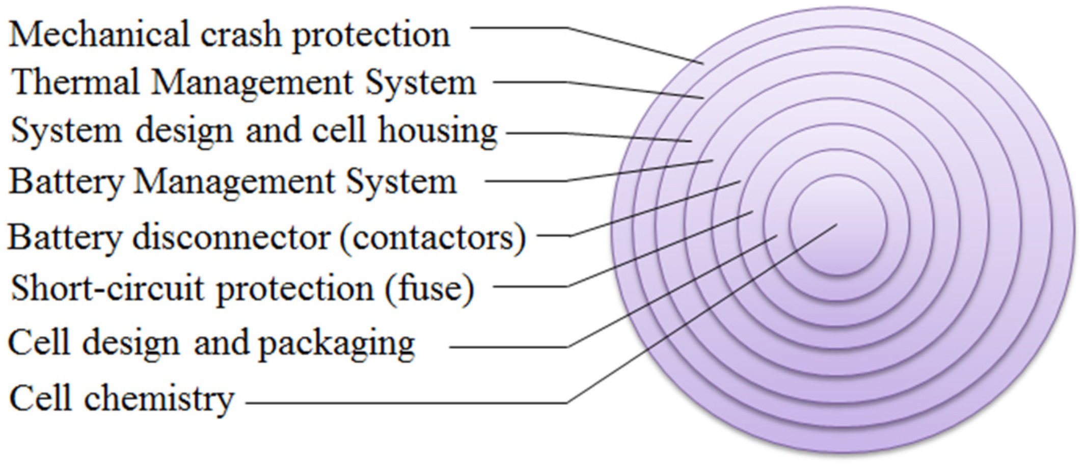
These incidents and their consequences clearly demonstrate the necessity of putting safe vehicles on the market, not only for the safety of humans in or near the vehicles, but also for economic and environmental reasons. The EV has the potential to be safer than conventional combustion engine cars, simply because the main fire source, gasoline/diesel, is removed [16]. In any case, the safety of a battery system depends on several things, e.g., cell chemistry, cell design and system design, including thermal management system and control strategies. Common cathode chemistries contain cobalt, e.g., lithium cobalt oxide (LCO), LiCoO2, lithium nickel manganese cobalt (NMC), LiNixMnyCozO2, and lithium nickel cobalt aluminum (NCA), LiNixCoyAlzO2. Lithium phosphates [17] are also used, e.g., lithium iron phosphate (LFP), LiFePO4. For the anode, various forms of carbon are dominant, while lithium titanate oxide (LTO), Li4Ti5O12, is used in lower volumes. This paper focuses mainly on carbon-LFP cells, which are currently seen as state of the art on the market when it comes to safety, although many battery systems for automotive applications use less stable chemistries in order to obtain, e.g., higher energy density. Abuse test results from cell level are presented and their impact is discussed on battery system and vehicle level.

2. Cells Studied

Cylindrical cells as well as pouch and soft-can prismatic cells have been tested. Cylindrical cells have a spirally wound layers inside an outer metal cylinder. The soft-can prismatic cell has a block shape and an outer cell packaging made of plastic material, in contrast to the hard-can prismatic cell, which has an outer metal packaging. In the pouch cell, the layers are stacked on top of each other and sealed by an aluminum-polymer bag. The pouch cell is often called a coffee bag cell or a polymer cell. Figure 1 shows an X-ray photo of the EiG pouch cell. The layered structure is clearly visible, where the white-/gray-colored layers are the separator material.
Table 1 shows the cells and their specifications for the abuse tests presented in this paper and Figure 2 shows photos of the cells. Most of the cells have a LFP-cathode and a carbon-based anode as seen from Table 1. The initial state of charge (SOC) level of the cells was achieved by charge/discharge procedures using a Digatron battery test equipment or an ordinary laboratory power aggregate. The cells had not been used prior to the measurements, but had different calendar ageing. The EiG and Lifetech cells had approximately two to three years of calendar aging, while the European Battery cells were less than six months old and the Samsung, EVE and GBS cells were about one year old. Cylindrical cells of type 18650, i.e., 18 mm in diameter and 65 mm long, are produced in very large volumes and are traditionally used in laptops, power tools and electric bikes. Laptop computers are nowadays often too thin to use 18650 cells and use instead pouch cells. Besides the use of 18650 cells in portable devices, Tesla Motors has chosen the 18650 cell format as a basis for its serial-production of EVs, while other vehicle manufacturers have chosen the prismatic or pouch cell type.

3. Thermal Runaway

Thermal runaway was studied using the external heating abuse test for a commercial 18650 laptop cell that is produced in large quantities by Samsung. The cell was fastened to a brick and placed inside a thermostatically controlled oven, the Binder FED 115, and heated up in about 1 h to the thermal runaway temperature [3]. The cell voltage and the cell surface temperature (measured by four type K thermocouples) as well as the oven air temperature (measured with one type K thermocouple) were measured with 1 Hz. Figure 3 shows the cell voltage and the differential temperature, ΔT, as a function of the oven temperature. The differential temperature is the difference between the average cell surface temperature and the oven temperature. Before the thermal runaway, the cell voltage breakdown occurs due to melting of the separator, an endothermic process which is observable as a small local decrease of ΔT. ΔT has negative values up to 220 °C due to higher oven temperature than cell temperature, while the thermal runaway occurs at 220 °C. The cell surface temperature increases to close to 800 °C (ΔT above 500 °C), with a maximum rate of around 5000 °C/min. Observations from the video recording showed that the thermal runaway is accompanied with a pressure wave (i.e., shaking the video camera) and instant ignition. The duration of the fire is approximately 1 min.

4. Fire Characteristics on Cell Level

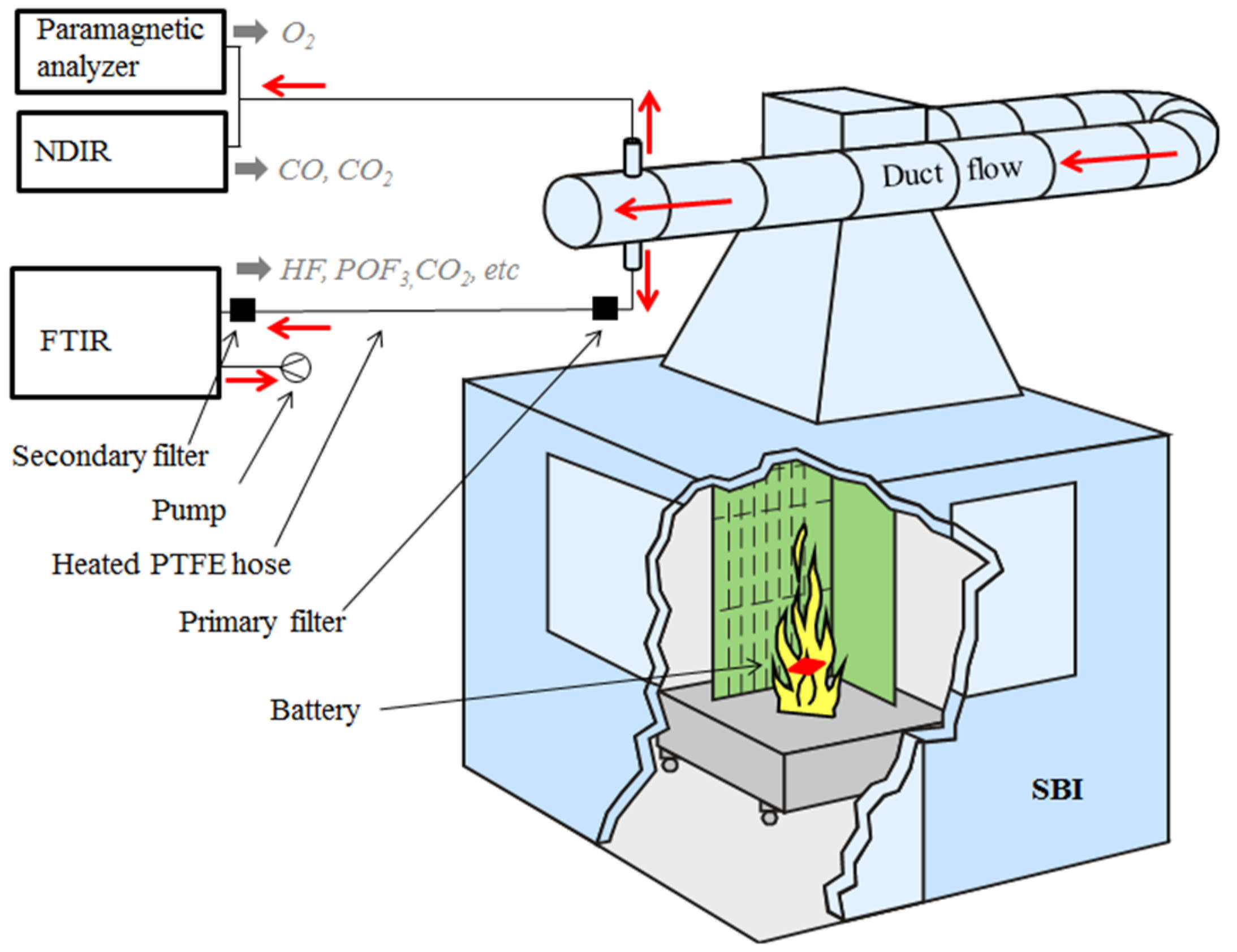
The measurement and gas collection system of the single burning item (SBI) apparatus were used for the fire tests. The SBI apparatus is normally used for the classification of building materials according to the European Classification scheme EN13823 [
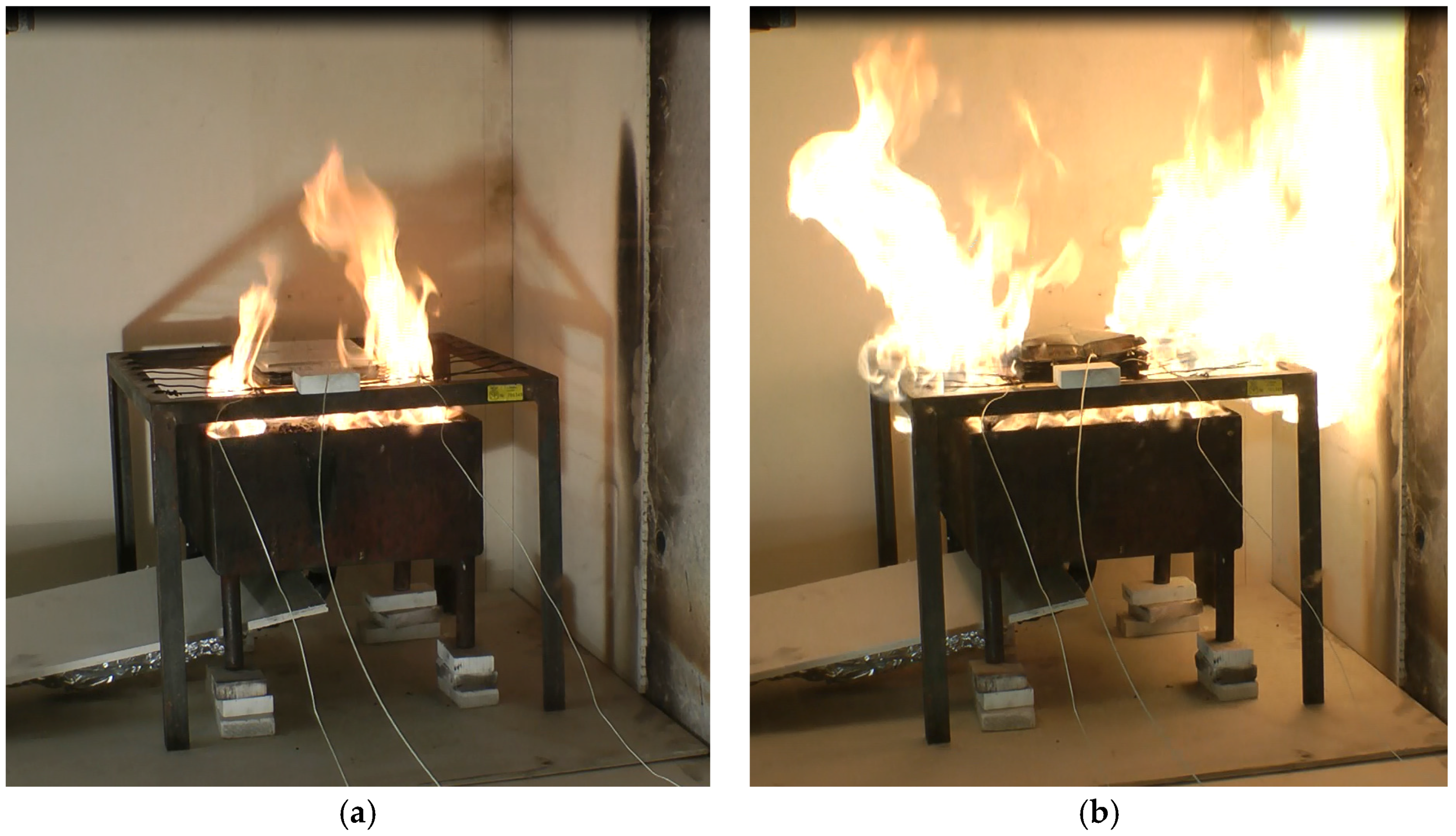
18]. The experimental setup is shown in 
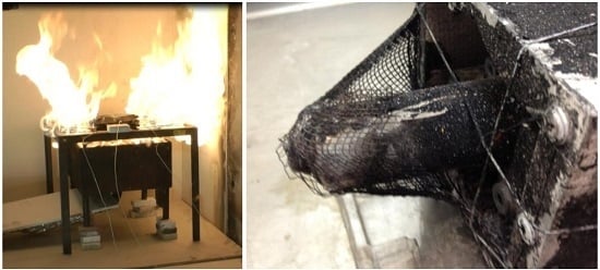
Figure 4. The battery cells were placed on a wire grating. A 15 kW propane burner was placed underneath the cells and was ignited 2 min after the start of the test.
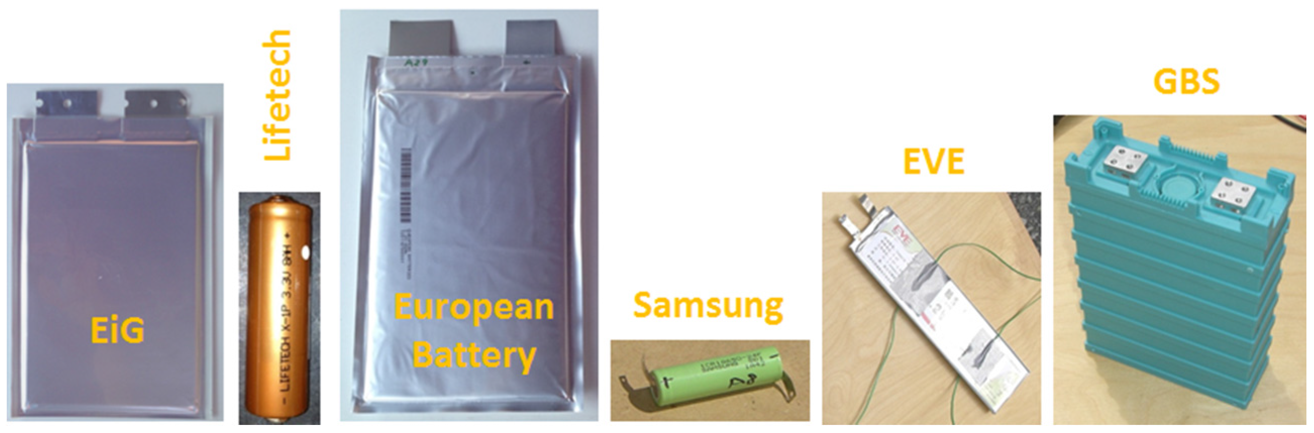
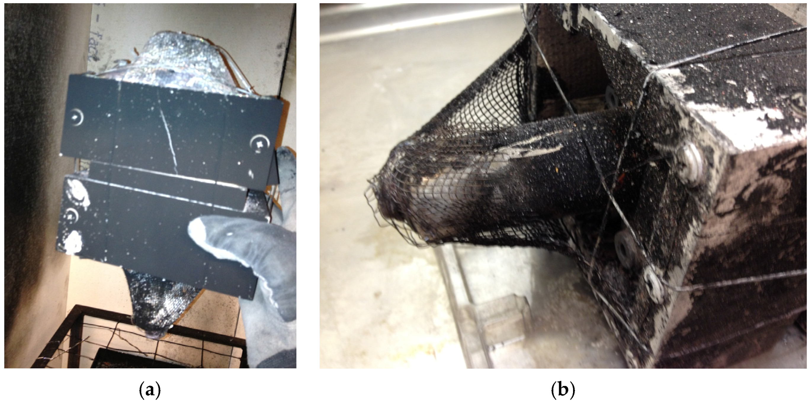
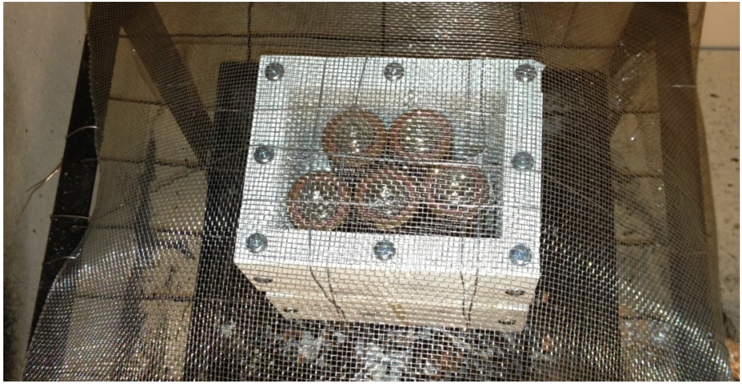
Tests were performed on EiG and Lifetech cells. Five cells were tested at the same time. The EiG cells were fastened together with steel wire, while the Lifetech cells were placed inside a protection box made of walls of non-combustible silica board and steel net at the bottom and top. Additionally, a secondary layer of steel net was used at the top, nailed to the wire grating to protect from hazardous projectiles (Figure 5). A blank test was conducted at the beginning of each test day in order to make a blank for the gas analysis and to measure the burner influence on the heat release rate (HRR). HRR values were calculated by the oxygen consumption method and corrected for CO2 [18]. The gases from the fire were collected in the duct flow as seen in Figure 4. In the tests of EiG cells with 100% SOC a duct flow of 0.6 m3/s was used, while for the other tests of EiG cells and for the Lifetech cells, the flow was decreased to 0.4 m3/s in order to increase emission concentrations. All tests were video recorded. A heated (180 °C) sub-flow was taken out to the Fourier transform infrared spectroscopy (FTIR, Thermo Fisher Scientific, Waltham, MA, USA) with an Antaris IGS analyzer (Nicolet), with a gas cell (heated to 180 °C), that measured gases, e.g., hydrogen fluoride (HF). Each test used a fresh primary filter (heated to 180 °C) which was analyzed for fluoride content after the test. All fluoride found was assumed to be in the form of HF. For the measured HRR the combined expanded uncertainty is +/−5 kW. The detection limit was 2 ppm for HF. For a detailed description of the experiment, see Larsson et al. [4] and Andersson et al. [19].
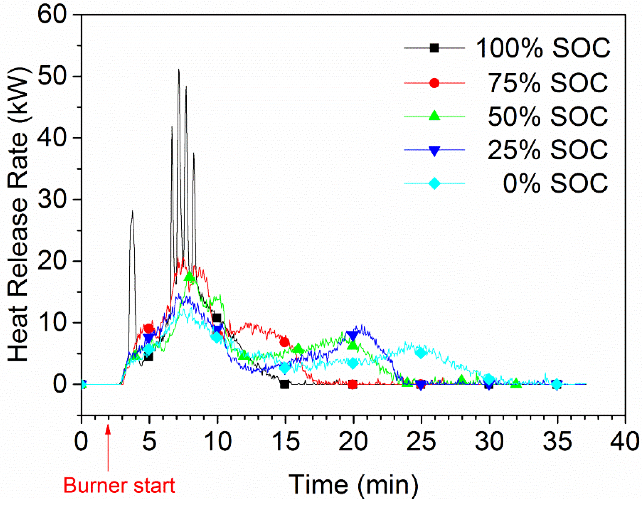
The HRR for various SOC levels for a five-cell-pack of EiG cells is shown in Figure 6. A strong dependence between SOC and HRR can be observed, and lower SOC values result in lower HRR peaks. For a 100% SOC, there are rapid heat releases and outbursts, one per cell, while no outburst or HRR peak can be seen for cells with a lower SOC.
For an example of an outburst see Figure 7. The total heat release (THR) has a relatively low dependence on SOC and was roughly 8 MJ for the five-cell-pack, corresponding to 6.5 MJ/kg battery cell. Ribière et al. [5] found, based on an 11 Wh pouch cell with LiMn2O4 (LMO) cathode, a heat of combustion of 4 MJ/kg, which is in the same order as that measured in our study.
The nominal energy content of the five-cell-pack is 112 Wh. Electrified vehicles typically have 10–30 kWh of batteries, and an extrapolation of our values to the energy released for this size of battery pack gives a THR of 700–2100 MJ, which corresponds to a fire of about 20–50 L of gasoline.

5. Projectile Hazards

Batteries can also cause projectile risks, which was demonstrated in one of the fire tests. Even though the cells were equipped with a safety valve, this did not prevent the explosion of one of the five Lifetech cylindrical cells as shown in Figure 8. Material from the cell interior was expelled while the cell moved backwards with a clear bang and a pressure wave formed a crater in the bed of small stones in the propane burner. No visual flaws of any kind could be observed for any of the five Lifetech cells before the test.
A simple teardown was conducted but no indications were found to understand why that cell exploded. Figure 9 shows photos during teardown. No separator could be observed in the cell, which was expected due to the high fire temperatures. The positive current collector of aluminum foil seemed to have melted completely. The copper foil was still present. The weight loss of the cell was 27%.

6. Cell Venting and Toxic Gases

The gases released from a Li-ion battery cell can be toxic, e.g., CO, but the fluoride emissions are of most concern. Hydrogen fluoride (HF) is one of them, but there are also others, e.g., phosphorous oxyfluoride (POF3). They are formed from the fluorine content used in the Li-ion cell; the binder (e.g., PVdF) and the commonly used Li-salt, hexafluorophosphate (LiPF6). The reaction formulas for the salt decomposition can be seen in the following equations [20]:
LiPF6 → LiF + PF5
PF5 + H2O = POF3 + 2HF
LiPF6 + H2O → LiF + POF3 + 2HF
HF has a relatively well-known toxicity [21], while the toxicity of POF3 is unknown. However, POF3 might be more toxic than HF as in the case of the chlorine analogue POCl3/HCl [22]. POF3 could not be observed in the fire tests on Li-ion cells reported here, but a fire study on electrolytes in a Cone calorimeter by Andersson et al. [19] indicated that the POF3 production might be approximately 1:20 of the HF production, which indicates that POF3 may also have been released in the present tests, but that the concentration was below the detection limit (6 ppm). In the previous study [
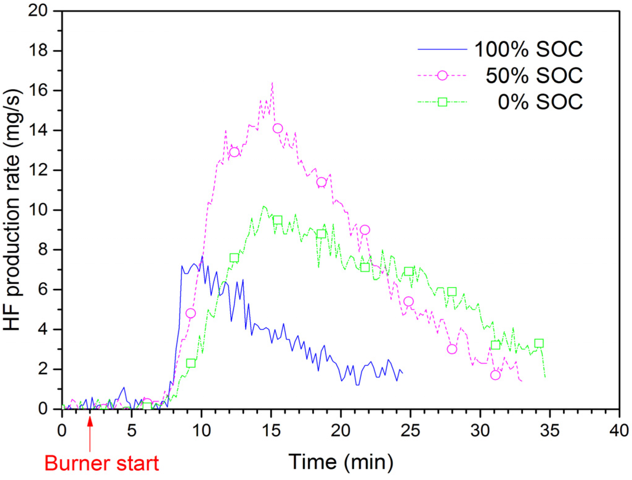
4], the real time HF production rate for EiG cells was determined. Figure 10 shows the HF production rate for EiG cells with different SOC during the fire tests. The highest rate is for 50% SOC, while 100% SOC has the lowest rate. The total amount of HF from both FTIR and the sampling filter is shown in Table 2, and values are between 5.6 g and 14 g HF for a five-cell-pack. Ribière et al. [5] measured HF in their studies of another type of pouch cell and, if we normalize their values against the cell electrical energy, a value of 37–69 mg/Wh is obtained, with the higher HF amounts for lower SOC, as seen in Table 2. These amounts are in the same order as our results, 50–120 mg/Wh; however, in contrast to this study, Ribière et al. [5] found the highest HF production rate for the fully charged (100% SOC) cells.
The extrapolation of the Larsson et al. [4] data to a larger battery pack size typically used in EVs gives an indication of the potential amount of released HF. A battery pack for an EV, based on the tested EiG cell, could, for example, have 432 cells. This corresponds to 108 cells in series and four cells in parallel, which results in a battery pack with 9.7 kWh and a 346 V nominal voltage. The extrapolation factor is then 432/5 = 86.4, resulting in about 400–1200 g HF, depending on the SOC level. These values are in the same order of magnitude as those reported by Lecocq et al. [23] for fire tests on a complete EV.

7. Cell Safety Mechanisms

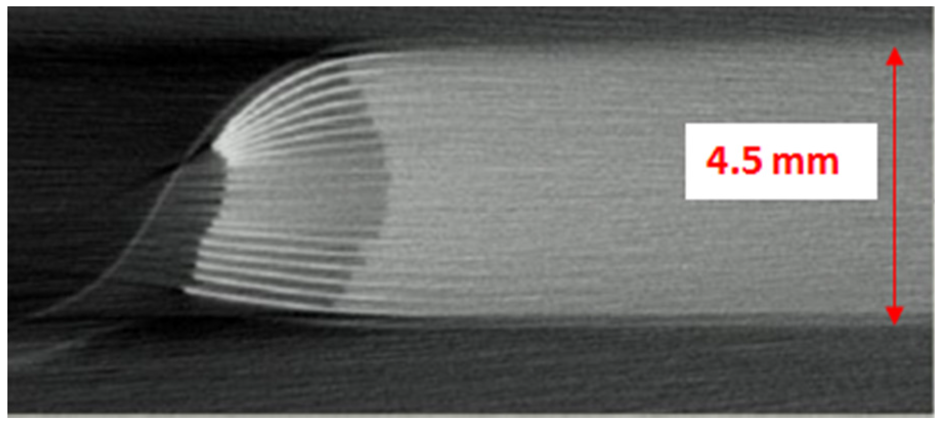
Cylindrical 18650 cells for consumer products typically have a cobalt or cobalt mixture-based cathodes (e.g., NMC, NCA), which are not as thermally stable as LFP [24]. A number of safety mechanisms [
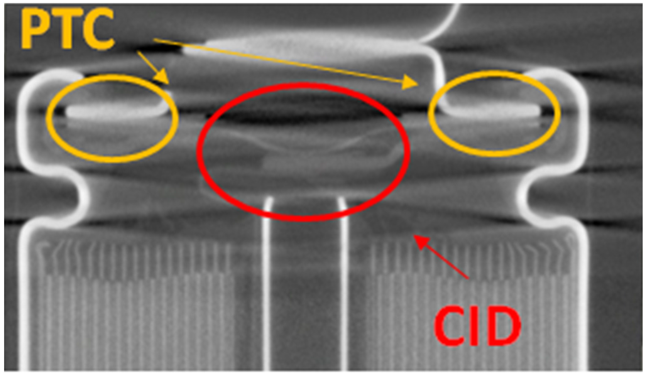
25] are often included in 18650 cells used in consumer products for low voltage systems. An example of such a safety mechanism is the current interrupter device (CID). The CID is a disc which is part of the current pathway. In case of overpressure in the cell, the CID is mechanically released due to the pressure, letting the cell go into open circuit mode. The CID is typically activated at a predesigned stage, before the cell can go into thermal runaway, by using shutdown additives [26]. Positive temperature coefficient (PTC) is another safety mechanism, which protects the cell by rapidly increasing the resistance in the current pathway when trigged by an overtemperature, significantly lowering the current passing through the cell. In any case, the CID and PTC do not work that well in battery systems with multiple cells that are electrically connected in a series and thereby at a higher voltage [27], e.g., in batteries used in electrified vehicles. Figure 11 shows a cross section X-ray photo of an 18650 cell where PTC and CID are shown.
Shutdown separators are widely used in commercial Li-ion batteries as a safety protection for some abuse situations, e.g., overcharge and short circuit. The pores in the separator are closed at overtemperatures, which lead to a hindered ion transport between cathode and anode and thus an open circuit. The shutdown separator usually consists of a layered structure where one layer has a lower melting temperature than the other layer. When the first layer melts the pores in the separator are closed, while the second layer sustains the cell integrity, thereby prohibiting internal short circuit. Figure 12 shows differential scanning calorimetry (DSC) measurements of a polypropylene (PP) separator and of a shutdown separator with polyethylene (PE) and PP; the latter exhibits two melting temperatures, corresponding to the two materials. In case of, e.g., an overcharge leading to an increased cell temperature, the PE will melt at around 130 °C, lowering the current and thereby the heating process. It may work less well in some situations, e.g., when the current is interrupted too late or when the cooling is poor due to the battery system design. In those cases, the melting temperature of the second layer of PP, around 160 °C, can be reached, leading to the total disintegration of the separator, followed by an internal cell short circuit. The use of shutdown separators in large battery systems has shown not to have the same safety benefits as in small batteries, since the higher battery voltage in cases where many cells are electrically connected in a series, as with EV batteries, for example, can lead to separator breakdown [28].
In order to account for the drawback that some of the typical safety devices used in cells for consumer products cannot be used in Li-ion cells for EVs, other safety mechanisms such as special additives in the electrolyte are used. Li-ion cells for EV typically use cells which have higher quality manufacturing, more pure raw materials and safer chemistry such as the LFP, which can withstand abuse better [3]. Figure 13 and 
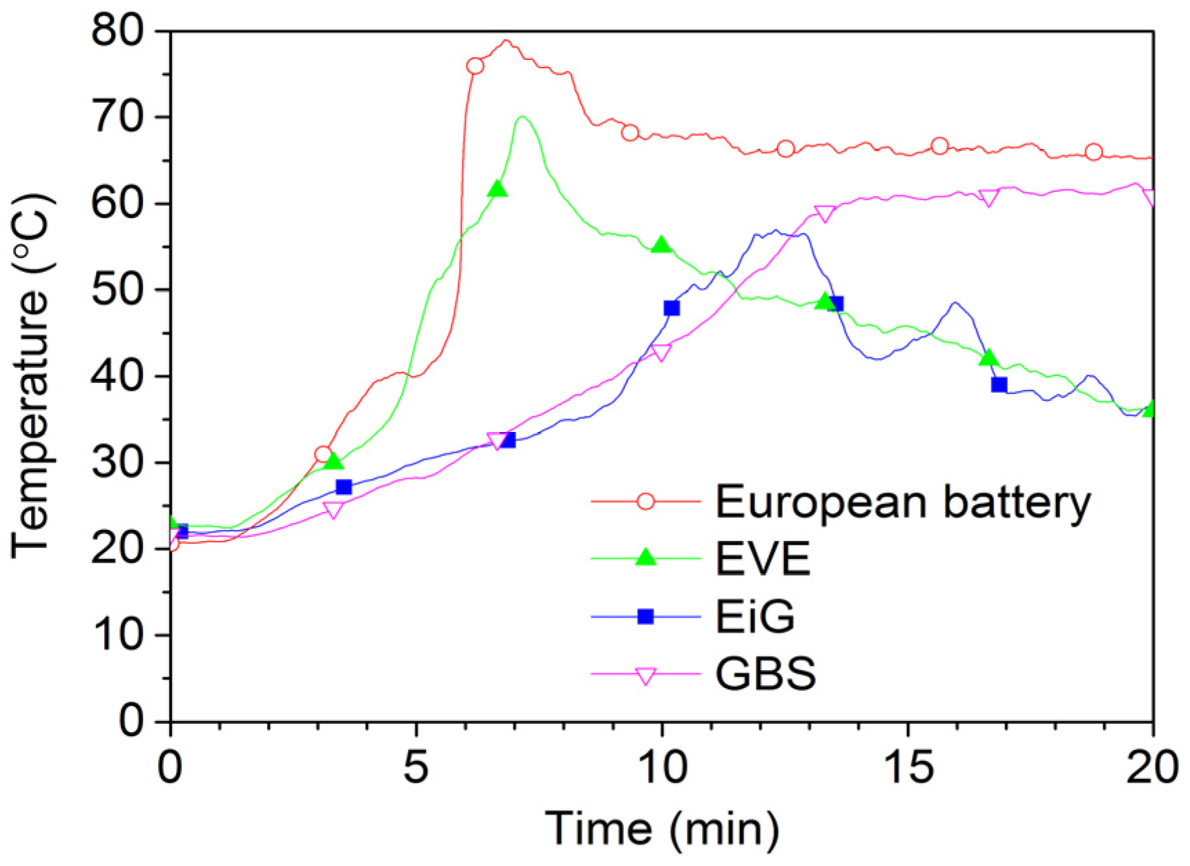
Figure 14 show 2C-rate overcharging of four LFP-based cells with a capacity between 7 Ah and 45 Ah. The GBS cell has a cathode of LFMP, i.e., LFP with manganese. The charger voltage was max 15.3 V and the charger was started after 1 min and was active during the complete test; however, for the overcharge of EVE, the charger was switched off at around 17 min, as seen by the voltage drop in Figure 14. The temperatures reached less than 80 °C, well below the onset temperature of the thermal runaway. However, the cells swell and gases are emitted. Four European battery cells were tested and the result from one of them is shown in Figure 13 and Figure 14. In fact, one of the European Battery cell unexpectedly caught fire. A situation of an overcharge abuse in the field might occur in case of a failure in the battery management system (BMS). High charge currents can occur, e.g., during fast charging or during breaking (recuperation) of an EV, which makes those cases especially sensitive to errors in the overcharge protection. In principle, the consequences for overcharging of LFP cells are less dramatic than for other Li-ion chemistries, but the temperature increase starts at a lower state of overcharge [24].
In the case of a short circuit of a Li-ion battery, the current can be very high [3]. A measurement of a low-ohmic short circuit on a single pouch cell from European Battery is shown in Figure 15. The voltage and current were measured with 1 kHz by an oscilloscope and cell surface temperatures (by 18 type K thermocouples on both sides of the cell) by a data logger at 1 Hz. The short circuit peak current is close to 1100 A and then lowered to a plateau of about 700 A. High currents generate a lot of heat, but for this cell the average temperature increase is only about 5 °C since the short circuit is stopped when the positive terminal burns off from the cell. In the case of a large battery pack with cell terminals that do not burn off, the current and the generated heat can be substantial, and in the case of burnt off terminal tabs the flames might ignite vented flammable battery gases or plastic parts inside a battery system.

8. Battery System and Electric Vehicle Level

High battery safety is accomplished by using many layers of actions of various safety techniques. Figure 16 shows the safety onion with examples of diverse safety actions used to ensure a low probability for fault, and to minimize the consequences of a fault. First, the cell chemistry is essential since this is the basis of the thermal stability. Second comes the cell design and packaging. In principle, there are three main levels: cell, battery system and vehicle level.

9. Conclusions

There is relatively good knowledge about the safety risks and safety devices used in consumer cells. Using Li-ion in the automotive sector puts higher demands on the battery since the batteries are significantly larger and have harsher environmental conditions, e.g., vibrations, humidity, larger temperature variations. The different Li-ion chemistries show diverse hazards where the LFP is less reactive but safety measures are still needed for all Li-ion batteries. A high level of safety is achieved by adding several safety layers from the cell to vehicle level; however, the risk for a cascading fire in a complete battery pack starting from a single cell is not yet well studied, and the knowledge about possible counteractions is thus also limited. Sometimes things go wrong even though smart safety strategies are used. The exploded cylindrical cell due to a cell vent malfunction showed this and underlines the importance of using many safety layers.
The toxic gas emissions from Li-ion batteries, e.g., HF and POF3, can pose a serious risk for a person. A replacement of the Li-salt LiPF6 to a non-fluorine salt and change of fluorine binder could resolve this risk. Intense research is ongoing in this field, but the required properties for a Li-ion battery in EVs are complex and demanding.

Acknowledgments

The Swedish Energy Agency is gratefully acknowledged for financial support. We are also indebted to several colleagues at SP and Chalmers who have contributed to this work.

Author Contributions

Fredrik Larsson conceived, designed and performed the experiments for all abuse types except for the fire tests where Petra Andersson and Fredrik Larsson did it together. All three authors were involved in the analyses of the data and wrote the paper.

Conflicts of Interest

The authors declare no conflict of interest.

References

  1. Golubkov, W.; Fuchs, D.; Wagner, J.; Wiltsche, H.E.; Stangl, C.; Fauler, G.; Voitic, G.; Thaler, A.; Hacker, V. Thermal-runaway experiments on consumer Li-ion batteries with metal-oxide and olivin-type cathodes. RSC Adv. 2014, 4, 3633–3642. [Google Scholar] [CrossRef]
  2. Long, R.T., Jr.; Blum, A.F.; Bress, T.J.; Cotts, B.R.T. Best Practices for Emergency Response to Incidents Involving Electric Vehicles Battery Hazards: A Report on Full-Scale Testing Results; Fire Protection Research Foundation: Quincy, MA, USA, 2013. [Google Scholar]
  3. Larsson, F.; Mellander, B.-E. Abuse by external heating, overcharge and short circuiting of commercial lithium-ion battery cells. J. Electrochem. Soc. 2014, 161, A1611–A1617. [Google Scholar] [CrossRef]
  4. Larsson, F.; Andersson, P.; Blomqvist, P.; Lorén, A.; Mellander, B.-E. Characteristics of lithium-ion batteries during fire tests. J. Power Sources 2014, 271, 414–420. [Google Scholar] [CrossRef]
  5. Ribière, P.; Grugeon, S.; Morcrette, M.; Boyanov, S.; Laruelle, S.; Marlair, G. Investigation on the fire-induced hazards of Li-ion battery cells by fire calorimetry. Energy Environ. Sci. 2012, 5, 5271–5280. [Google Scholar] [CrossRef]
  6. Fu, Y.; Lu, S.; Li, K.; Liu, C.; Cheng, X.; Zhang, H. An experimental study on burning behaviors of 18650 lithium ion batteries using a cone calorimeter. J. Power Sources 2015, 273, 216–222. [Google Scholar] [CrossRef]
  7. Huang, P.; Wang, Q.; Li, K.; Ping, P.; Sun, J. The combustion behavior of large scale lithium titanate battery. Sci. Rep. 2015, 5. [Google Scholar] [CrossRef] [PubMed]
  8. Ahrens, M. Automobile Fires in the U.S.: 2006–2010 Estimates. In Proceedings of the Fires in Vehicles (FIVE) Conference 2012, Chicago, IL, USA, 27–28 September 2012; Andersson, P., Sundström, B., Eds.; SP Technical Research Institute of Sweden: Borås, Sweden, 2012; pp. 95–104. [Google Scholar]
  9. Larsson, F.; Andersson, P.; Mellander, B.-E. Battery Aspects on Fires in Electrified Vehicles. In Proceedings of the Fires in Vehicles (FIVE) 2014 Conferences, Berlin, Germany, 1–2 October 2014; Andersson, P., Sundström, B., Eds.; SP Technical Research Institute of Sweden: Borås, Sweden, 2014; pp. 209–220. [Google Scholar]
  10. Investigation PE 13-037; National Highway Traffic Safety Administration (NHTSA): Washington, DC, USA, 2014. Available online: http://www-odi.nhtsa.dot.gov/acms/cs/jaxrs/download/doc/UCM452870/INCLA-PE13037-2071.PDF (accessed on 7 April 2016).
  11. Musk, E. Tesla Adds Titanium Underbody Shield and Aluminum Deflector Plates to Model S, 2014. Available online: http://www.teslamotors.com/blog/tesla-adds-titanium-underbody-shield-and-aluminum-deflector-plates-model-s (accessed on 10 February 2016).
  12. Aircraft Serious Incident Investigation Report; JA804A; Japan Transport Safety Board: Tokyo, Japan, 2014; Available online: http://www.mlit.go.jp/jtsb/eng-air_report/JA804A.pdf (accessed on 7 April 2016).
  13. Auxiliary Power Unit Battery Fire, Japan Airlines Boeing 787-8, JA829J, Boston, Massachusetts; NTSB/AIR-14/01; National Transportation Safety Board: Washington, DC, USA, 2014. Available online: http://www.ntsb.gov/investigations/AccidentReports/Reports/AIR1401.pdf (accessed on 7 April 2016).
  14. U.S. Department of Transportation, Federal Aviation Administration. Safety Alert for Operators, SAFO 16001, 1/19/2016. Available online: http://www.faa.gov/other_visit/aviation_industry/airline_operators/airline_safety/safo/all_safos/media/2016/SAFO16001.pdf (accessed on 7 April 2016).
  15. International Air Transport Association (IATA). Lithium Batteries as Cargo in 2016 Update III, 2016. Available online: http://www.iata.org/whatwedo/cargo/dgr/Documents/lithium-battery-update.pdf (accessed on 25 February 2016).
  16. Larsson, F.; Andersson, P.; Mellander, B.-E. Are electric Vehicles Safer than Combustion Engine Vehicles? In Systems Perspectives on Electromobility; Sandén, B., Wallgren, P., Eds.; Chalmers University of Technology: Göteborg, Sweden, 2014; pp. 33–44. [Google Scholar]
  17. Padhi, A.K.; Nanjundaswarmy, K.S.; Goodenough, J.B. Phospho-olivines as positive-electrode materials for rechargeable lithium batteries. J. Electrochem. Soc. 1997, 144, 1188–1194. [Google Scholar] [CrossRef]
  18. Reaction to Fire Tests for Building Products—Building Products Excluding Floorings Exposed to the Thermal Attack by a Single Burning Item; EN 13823:2010; European Committee for Standardization: Brussels, Belgium, 2010.
  19. Andersson, P.; Blomqvist, P.; Lorén, A.; Larsson, F. Investigation of Fire Emissions from Li-ion Batteries; SP Report 2013:5; SP Technical Research Institute of Sweden: Borås, Sweden, 2013. [Google Scholar]
  20. Yang, H.; Zhuang, G.V.; Ross, P.N., Jr. Thermal stability of LiPF6 salt and Li-ion battery electrolytes containing LiPF6. J. Power Sources 2006, 161, 573–579. [Google Scholar] [CrossRef]
  21. Documentation for Immediately Dangerous to Life or Health Concentrations (IDLHs) for Hydrogen Fluoride (As F); The National Institute for Occupational Safety and Health (NOISH): Washington, DC, USA, 1994.
  22. Middelman, A. Hygiensiska Gränsvärden AFS 2011:18, Hygieniska Gränsvärden Arbetsmiljöverkets Föreskrifter och Allmänna råd om Hygieniska Gränsvärden; Swedish Work Environment Authority: Stockholm, Sweden, 2011. (In Swedish) [Google Scholar]
  23. Lecocq, A.; Bertana, M.; Truchot, B.; Marlair, G. Comparison of the Fire Consequences of an Electric Vehicle and an Internal Combustion Engine Vehicle. In Proceedings of the International Conference on Fires in Vehicles (FIVE) 2012, Chicago, IL, USA, 27–28 September 2012; Andersson, P., Sundström, B., Eds.; SP Technical Research Institute of Sweden: Borås, Sweden, 2012; pp. 183–194. [Google Scholar]
  24. Doughty, D.; Roth, E.P. A general discussion of Li ion battery safety. Electrochem. Soc. Interface 2012, 2012, 37–44. [Google Scholar]
  25. Balakrishnan, P.G.; Ramesh, R.; Kumar, T.P. Safety mechanisms in lithium-ion batteries. J. Power Sources 2006, 155, 401–414. [Google Scholar] [CrossRef]
  26. Zaghib, K.; Dubé, J.; Dallaire, A.; Galoustov, K.; Guerfi, A.; Ramanathan, M.; Benmayza, A.; Prakash, J.; Mauger, A.; Julien, C.M. Lithium-Ion Cell Components and Their Effect on High-Power Battery Safety. In Lithium-Ion Batteries: Advances and Applications; Pistoia, G., Ed.; Elsevier: Amsterdam, The Netherlands, 2014; Chapter 19; pp. 437–460. [Google Scholar]
  27. Jeevarajan, J. Safety of Commercial Lithium-Ion Cells and Batteries. In Lithium-Ion Batteries: Advances and Applications; Pistoia, G., Ed.; Elsevier: Amsterdam, The Netherlands, 2014; Chapter 17; pp. 387–407. [Google Scholar]
  28. Orendorff, C.J. The role of separators in lithium-ion cell safety. Electrochem. Soc. Interface 2012, 2012, 61–65. [Google Scholar]
Figure 1. X-ray photo of EiG pouch cell seen at one of the edges.
Batteries 02 00009 g001
Figure 2. Photo of tested cells, not at same physical scale.
Batteries 02 00009 g002
Figure 3. External heating test of a Samsung 18650 laptop cell.
Batteries 02 00009 g003
Figure 4. Schematic illustration of the experimental setup. NDIR: non-dispersive infrared; FTIR: Fourier transform infrared spectroscopy; and SBI: single burning item.
Batteries 02 00009 g004
Figure 5. Lifetech single cells before the fire test at 100% SOC with external propane burner.
Batteries 02 00009 g005
Figure 6. Heat release rate (HRR) for the five-cell pack of EiG 7 Ah cell, using an external propane burner (burner HRR has been subtracted from the graph). Cell SOC varied from 0% to 100%.
Batteries 02 00009 g006
Figure 7. Photo in the beginning (a) of the fire test of a 100% SOC EiG five-cell-pack, and photo of an outburst (b) during the fire test.
Batteries 02 00009 g007
Figure 8. Photos of the exploded Lifetech cell in the protection box after the fire test at 100% SOC with external propane burner: (a) seen from the side of the box; and (b) close up of bottom of the box.
Batteries 02 00009 g008
Figure 9. Photos of the exploded Lifetech cell during tear-down: (a) the exploded cell and part of the protection box and two adjacent cells; and (b) exploded cell alone.
Batteries 02 00009 g009
Figure 10. The rate of hydrogen fluoride (HF) production for an EiG five-cell pack for 100%, 50% and 0% SOC.
Batteries 02 00009 g010
Figure 11. X-ray photo of an 18650 cell with the positive temperature coefficient (PTC) and current interrupter device (CID) marked.
Batteries 02 00009 g011
Figure 12. Differential scanning calorimetry (DSC) measurements of two different separator materials, one shutdown separator with polyethylene-polypropylene (PE-PP) and one with only PP. The DSC measurements used a liquid N2 cooled Mettler DSC-30 (Greifensee, Switzerland), the samples were purged with N2, and heated between 25 °C and 185 °C with a heating rate of 5 °C/min.
Batteries 02 00009 g012
Figure 13. Overcharge tests of LFP and LFMP cells, with charge current of 2C-rate, showing average cell surface temperature development.
Batteries 02 00009 g013
Figure 14. Overcharge tests of LFP and LFMP cells, with charge current of 2C-rate, showing cell voltage (solid lines) and SOC development (dashes lines). SOC is calculated by cumulative integration of the measured current and time, divided by the nominal capacity.
Batteries 02 00009 g014
Figure 15. Short circuit of a European Battery pouch cell.
Batteries 02 00009 g015
Figure 16. The safety onion showing examples, layer by layer, of different safety actions that can be used to establish a safe battery system in electric vehicles (EVs).
Batteries 02 00009 g016
Table 1. Cell and test specifications. SOC: state of charge; LFP: lithium iron phosphate; and LFMP: LFP with manganese.
CellNominal Cell Capacity (Ah)Nominal Cell Voltage (V)Cathode/AnodeCell PackagingTest Type Presented in This PaperInitial SOC (%)
EiG ePLB-F007A73.2LFP/carbonPouchPropane fire, overcharge0–100
Lifetech X-1P83.3LFP/carbonCylindricalPropane fire100
European Battery453.2LFP/carbonPouchShort circuit, overcharge100
Samsung ICR18650-24F2.43.6Cobalt based/carbonCylindricalExternal heating (oven)100
EVE F7568270103.2LFP/carbonPouchOvercharge100
GBS LFMP40Ah403.2LFMP/carbonPrismaticOvercharge100
Table 2. Emissions of hydrogen fluoride for 100%, 50% and 0% SOC based on results from Larsson et al. [4].
SOC (%)Max Rate of HF Production (mg/s)Total Amounts of HF (g)Total Amount of HF (mg/Wh)
Our MeasurementsCalculated from Ribière et al. [5]
1008.35.65037
50161412039
0101110069

