
Comprehensive Review of Energy Storage Systems Characteristics and Models for Automotive Applications
by
 , , and
Armel Asongu Nkembi
1 ,
,
Marco Simonazzi
1,
Danilo Santoro
1,
Paolo Cova
1,2 and
Nicola Delmonte
1,2,* 1
Department of Engineering and Architecture, University of Parma, 43124 Parma, Italy
2
CIDEA—Centro Interdipartimentale per l’Energia e l’Ambiente, University of Parma, 43124 Parma, Italy
*
Author to whom correspondence should be addressed.
Batteries 2024, 10(3), 88; https://doi.org/10.3390/batteries10030088
Submission received: 25 December 2023
/
Revised: 21 February 2024
/
Accepted: 28 February 2024
/
Published: 2 March 2024
Abstract
:Currently, the electrification of transport networks is one of the initiatives being performed to reduce greenhouse gas emissions. Despite the rapid advancement of power electronic systems for electrified transportation systems, their integration into the AC power grid generates a variety of quality issues in the electrical distribution system. Among the possible solutions to this challenge is the inclusion of continuous storage systems, which can be located either onboard or offboard. The rapid development of energy storage devices has enabled the creation of numerous solutions that are leading to ever-increasing energy consumption efficiency, particularly when two or more of these storage systems are linked in a cascade and a hybrid mode. The various energy storage systems that can be integrated into vehicle charging systems (cars, buses, and trains) are investigated in this study, as are their electrical models and the various hybrid storage systems that are available.
1. Introduction
Due to the increasing greenhouse gas emissions from the burning of carbon-containing fossil fuels like crude oil, coal, and natural gas, climate change and global warming are becoming an increasingly serious threat to our environment and health. A quick switch away from fuels based on carbon is necessary to reduce greenhouse gas emissions and stop further climatic instability [1]. Renewable energy sources like solar power, wind power, hydroelectric power, biomass, and ocean power are being increasingly recognized as a means of lowering the carbon footprint due to their abundant supply and low emissions. However intermittent renewable energy sources like wind and solar energy also raise new concerns about the AC grid’s reliability, flexibility, and power quality. As a result, energy storage systems (ESSs) are being developed to deal with these problems [2]. Additionally, in the transportation industry, internal combustion engines (ICEs) that depend on the consumption of fossil fuels are being replaced by electric vehicles (EVs). Consequently, EVs have a significant impact on reducing the environmental issues brought about by the use of ICEs. As a result, energy storage is required in these EVs to provide the electric power needed to drive the electric motors and perform other functions such as air conditioning and navigation lighting [3].
ESSs are classified into five types: electromagnetic, electrochemical, mechanical, chemical, and thermal. Some of the most commonly used ESSs for automotive applications include Supercapacitors (SCs), flywheels, batteries, Compressed Air Energy Storage (CAES), and hydrogen tanks [4]. Each storage system is unique in terms of its power rating, discharge time, power and energy density, response speed, self-discharge losses, life and cycle time, etc. These characteristics should be considered when determining their suitability for various support roles. In order to carry out these functions, power electronic converters are crucial in managing the flow of power between the AC grid, EV electric motors, and ESSs. Additionally, different bidirectional converters (DC–DC, DC–AC, and AC–AC) are used to enhance system performance characteristics like efficiency, reliability, output harmonic distortion, and power density [5].
When two or more ESSs are combined, a hybrid energy storage system (HESS) is formed, which aids in overcoming the shortcomings of each energy storage device. There has been a lot of research on the best architecture for HESSs, and solutions vary depending on system complexity, flexibility, and cost [6]. Batteries and supercapacitors are the most common HESS, and numerous works in the literature explain their operation, sizing, and control principles [7,8]. Ref. [9] proposes a new bidirectional DC–DC converter which can be used in hybrid electric vehicle (HEV) systems to connect a main storage block with an auxiliary storage, and a DC-bus with many voltages. The proposed converter is capable of operating in both step-up and step-down modes, with bidirectional power flow control. Furthermore, ref. [10] proposes a new regenerative braking system (RBS) for EVs powered by a brushless DC (BLDC) motor with HESS (battery and supercapacitor). The authors employ a suitable switching algorithm to increase the DC-link voltage and transfer energy to the battery or SC via the inverter, which is used to improve vehicle acceleration and prevent the battery pack from discharging while driving uphill. In addition, the authors of [11] propose a model predictive-control-based standalone energy management system for HESS in EVs that does not require knowledge of vehicle speed or future demands and thus does not require interfacing with the motor drive system.
There are review papers in the literature that focus on separate aspects of energy storage systems, such as highlighting the characteristics of these storage systems [12,13] or providing only their electrical circuit models [14,15], while others only briefly discuss some possible schemes for connecting these storage systems in hybrid mode for power electronic applications [16]. However, given the importance of this topic, it is necessary to have a single paper that comprehensively surveys all these aspects of energy storage systems, beginning with their operational principles, characteristics, and how they compare with each other, as well as their various electric models, and the different schemes for connecting them in a hybrid mode. All of these aspects are presented in this paper for the first time, and are thus regarded as the paper’s major contribution.
The rest of this paper is organized as follows: Section 2 provides the characteristics of the most commonly used energy storage systems that can be integrated into e-mobile systems, while Section 3 presents the different power electronic models used to emulate the behavior of these storage systems in simulations. Section 4 talks about the different hybrid topologies that can be used to cascade the various energy storage devices (ESDs) while Section 5 presents the different challenges facing the adoption of energy storage at present. The work is finally concluded in Section 6.
2. Characteristics of Energy Storage Technologies for Automotive Systems
In the automotive industry, many devices are used to store energy in different forms. The most commonly used ones are batteries and supercapacitors, which store energy in electrical form, as well as flywheels, which store energy in mechanical form. Other less commonly used storage devices include fuel cell hydrogen tanks and compressed-air systems, which store energy in chemical and mechanical forms, respectively.
2.1. Batteries
Batteries are the most commonly used energy storage devices in power systems and automotive applications. They work by converting their stored internal chemical energy into electrical energy. Currently, three types of batteries are used in automotive applications: lead–acid batteries, nickel-based batteries, and lithium-ion batteries. Other less popular ones on the market include sodium sulfur batteries, metal–air batteries, and flow batteries, which will not be looked at in this paper [17]. Aqueous zinc-ion batteries (AZIBs), which use water electrolytes instead of organic electrolytes, are also worthy of mention. Even though they are still only in the experimental phase, they have attracted substantial scientific and industrial attention due to their safety (they are non-flammable), good thermal stability, great cycling performance, cost-effectiveness, and environmental friendliness when compared to other organic-based batteries. AZIBs have energy densities of up to 361 Wh/kg due to the use of zinc metal anodes with high gravimetric and volumetric capacities of 820 mAh/g and 5855 mAh cm–3, respectively, and low redox potential −0.762 V [18,19,20].
Lead–acid batteries are the most traditional rechargeable electrochemical devices for both residential and commercial use. The lead–acid battery types more commonly used are the Vented Lead Acid (VLA), also known as “flooded”, and the Valve Regulated Lead Acid (VRLA) which is shortly called “sealed”. The first type is less expensive than the second one; however, it requires some maintenance due to the need for monthly checks and replacement of the battery’s distilled water, as well as ventilation due to the formation of flammable gases [21]. Lead–acid batteries are currently employed in a variety of applications, including vehicle starter battery services, UPS units, mobile power applications like forklifts, and small photovoltaic (PV) systems [22]. Lead–acid batteries have low capital costs (60–200 USD/kWh), high energy efficiency (63–90%), a quick response, and low self-discharge rates (about 2% of rated capacity per month at 25 °C). Lead–acid batteries, however, are characterized by low specific energy density (25–50 Wh/kg) and short cycle life (500–1500 cycles). Because they contain harmful elements, environmental issues also occur during the production or disposal of these batteries [17]. They are also hefty and have poor low-temperature properties, and they cannot be left discharged for too long without causing harm [21,22]. These disadvantages limit the widespread commercial use of lead–acid batteries.
Batteries based on nickel are of four major types: nickel-cadmium (NiCd), nickel-metal hydride (NiMH), nickel-iron (NiFe), and nickel-zinc (NiZn) batteries. Nickel-based batteries offer good ruggedness/robustness characteristics. They can resist to different electrical uses as they can be left in a discharged condition for long periods without permanent damage, although they need to be primed before use, and they also offer good performance in high ambient temperatures [23] as well as low temperatures [24].
NiCd batteries in some applications can compete with lead–acid batteries because they offer similar features but have greater cycling capabilities (>3500 cycles), power densities, and energy densities (40–75 Wh/kg) [25]. Despite the advantages that they possess, they have some limitations. NiCd has a memory effect that causes a loss of capacity when it is not periodically fully discharged [24]. They also possess higher self-discharge rates compared to lead–acid batteries and hence need recharging after storage. In addition, cadmium is a toxic metal; hence, there are issues associated with the disposal of Ni-Cd batteries. Furthermore, they possess a low cell voltage of 1.20 V and require many cells to achieve a high voltage. Finally, they have relatively high costs because the manufacturing process is expensive (about 5–10 times the cost of a comparable lead–acid battery) [26].
Ni-MH batteries have about 1.5–2 times higher specific energy (70–100 Wh/kg) and relatively higher energy density (100–320 Wh/L) than NiCd. They exhibit high specific power (>200 W/kg) and a higher power density compared to lead–acid batteries, but these qualities are lower than those of NiCd [27]. They also show tolerance to overcharge/discharge, and are environmentally compatible and safe since they contain only mild toxins [28]. Also, they are less prone to memory effects than NiCd and have a longer cycle life in comparison with lithium-ion batteries [25]. Probably, the main problem of nickel–metal hydride batteries is their high cost. Other concerns include their high self-discharge rates due to active material decomposition, low-temperature operation, and higher cooling requirements. They also tend to generate heat during fast charge and high-load discharge and their service life is reduced if they are deeply discharged [24].
NiFe batteries are resilient to overcharge and over-discharge and can last for more than 20 years in standby applications. They also exhibit high resistance to vibrations and high temperatures. They can remain discharged for long periods without damage. They are also environmentally friendly and safe. NiFe batteries, however, have a low specific energy of about 50 Wh/kg and a low energy density of about 30 Wh/L, poor low-temperature performance, and exhibit a high self-discharge of 20–40 percent a month. In addition, they have high manufacturing costs as they cost almost four times as much as lead–acid and lithium batteries [29] although they are less expensive than NiCd batteries. They are also very heavy and bulky and have a low coulombic efficiency, typically less than 65%. Finally, the open-circuit voltage of these cells is 1.4 V and their discharge voltage is about 1.2 V; therefore, they require many stacked cells to achieve higher voltages [30].
NiZn provides 1.65 V/cell rather than 1.20 V, which NiCd and NiMH deliver. Currently, NiZn batteries have contained specific energies of about 50–60 Wh/kg and energy densities of about 80–120 Wh/L depending on the specific design. They also exhibit good cycle characteristics as they can deliver more than 500 cycles at 100% Depth of Discharge (DoD) and up to several thousand cycles at a low DoD [31]. NiZn has no heavy toxic materials and can easily be recycled. The chemistry of NiZn batteries is excellent when discharge rates are high (since their internal resistance is low) while maintaining thermal stability. They are also capable of fast recharging [32]. Despite the above-mentioned advantages, they tend to be much more costly than lead–acid batteries.
Lithium-ion batteries are one of the most popular types of rechargeable batteries available on the market for use in automotive applications due to the advantages they possess. They have one of the highest specific energies (150–350 Wh/kg) and energy densities (100–800 Wh/L) of any battery technology, as shown in Figure 1, a high open-circuit voltage (they can deliver up to 3.6 V, which is three times higher than technologies like NiCd and NiMH), a low self-discharge rate of about 1.5–2% per month, no memory effect, which is an advantage over NiCd and NiMH, both of which display this effect, and also exhibit a slow loss of charge when not in use [33,34]. They do not contain toxic cadmium, which makes them easier to dispose of than Ni-Cd batteries. Despite their technological promise, Li-ion batteries have a number of flaws, most notably in terms of safety. Li-ion batteries tend to overheat and are susceptible to damage at high voltages. Thermal runaway and combustion can occur in some cases. For these reasons, Lithium-ion batteries require safety mechanisms to limit voltage and internal pressure, which can increase their weight and, in some cases, limit their performance. They too are subject to aging with loss of capacity. Often, if not used carefully, they fail after a few years. Another barrier to widespread adoption is their high cost, which is approximately 40% higher than that of Ni-Cd [34].
2.2. Supercapacitors
SCs, also called ultracapacitors (UCs), are energy storage devices operating with a behavior that fits between that of batteries and that of conventional capacitors. Supercapacitors can be classified into three main categories that consider the cell configuration, the charge storage mechanism, and the electrode and electrolyte materials: electric double-layer capacitors (EDLCs), pseudocapacitors (PCs), and hybrid supercapacitors (HSCs) [35]. They can store more energy than capacitors and provide more power than batteries (their specific power is between 2 and 10 kW/kg and power densities are in the range of 40–120 kW/L). These characteristics, along with their exceptionally high cyclability (typically higher than 500,000 cycles, which gives them a long life) and long-term stability, make SCs appealing energy storage devices [36]. SCs are required to have a high working voltage, large capacitance, and low resistance for use in pulse power applications. However, the working voltage of existing supercapacitors is typically less than 3.5 V. This necessitates that they are stacked together in series to increase the voltage, but this inevitably reduces the total capacitance of the system and increases the internal resistances, which account for more power losses [37]. The capacitance and internal resistance of supercapacitors could be enhanced by connecting them in parallel [22]. Supercapacitors also have very short charge/discharge times, usually between a few seconds and minutes, and have efficiencies between 90 and 94%. However, they cannot be used for long-term storage applications because of their very high self-discharge per day (about 20–40%); therefore, they are only suitable for short-term storage applications [38]. They also have a low specific energy (2–5 Wh/kg) and energy density (10–30 Wh/L) when compared to traditional batteries. As a result of this, they can be used in hybrid applications with batteries, where batteries provide the long-term energy demanded by the system whereas the supercapacitors provide the short-term power. Another challenging problem for SCs is their high capital costs, which are usually about 10,000 USD/kWh [39].
2.3. Flywheels
Flywheels are systems capable of storing energy in rotational kinetic form [40]. A flywheel energy storage system (FESS) is shown in Figure 2 and is made up of five primary components: a flywheel (rotating disc), a group of bearings, a reversible electrical motor/generator, a power electronic unit, and a vacuum chamber [41]. This technology is based on the fact that the electricity whose energy we want to store drives an electric motor that turns a flywheel for thousands of revolutions per minute, maintaining kinetic energy over time. [42]. During the discharge process, i.e., when you want to extract electricity from the system, the flywheel rotates the shaft connected to that of the electric generator which produces electricity [43]. Placing the flywheel to rotate in a vacuum chamber helps to ensure there are no losses due to aerodynamic resistance, hence improving the efficiency of energy conversion [44].
The amount of energy stored in a flywheel depends on the speed of rotation of the flywheel, as well as its moment of inertia, as defined by Equation (1).
where EK is the rotational kinetic energy stored in the flywheel, Im is the moment of inertia, mf is the flywheel mass, ωf is the flywheel speed, rf is the radius of the flywheel, and K is the form factor, which depends on the shape of the flywheel.
There are two main groups of FESS: low-speed and high-speed. Low-speed FESS uses steel as a material and rotates below 6 × 10³ rpm. It has a specific energy of about 5 Wh/kg. On the other hand, high-speed FESS uses advanced composite materials like carbon fiber and can rotate at speeds up to about 105 rpm. It also uses non-contact magnetic bearings to reduce the wear of bearings, thereby improving the efficiency. It has been shown to achieve a specific energy of about 100 Wh/kg. However, it has higher costs when compared with low-speed FESS [41].
FESSs have many advantages, such as their high roundtrip efficiency (90–95%), exceptionally long lifetime (15–20 years), low maintenance cost, and fast response [42,45]. No greenhouse emissions or toxic material are produced when flywheels are working, so they are very environmentally friendly [44]. Moreover, compared with batteries, this storage system can operate under a wider range of temperatures [43]. Some issues associated with FESS include its high capital cost (1000–5000 USD/kWh) [45], and high self-discharge rates (3–20% of stored capacity per hour) resulting from idling losses during periods when the flywheel is not being used [41,46]. As a result of their high self-discharge, FESSs are effective only when storing energy for short periods. Therefore, they cannot be used as a standalone backup power unless operated with another ESS, like a battery. Another issue is that they have limited capacities (3–130 kWh) [42].
2.4. Hydrogen Tank Storage
The notion of using hydrogen as a raw material to power future cars has recently attracted attention due to its abundance, clean nature, and high energy density of 120 MJ/kg, which is almost three times that of diesel or gasoline. While battery electric vehicles (BEVs) have grown in popularity and sales globally over the last decade, the adoption of hydrogen vehicles has been gradual, with one of the main reasons being difficulties in the onboard storage of the flammable hydrogen [47]. Compressed hydrogen storage presents itself as the most promising on-board storage solution because of its superior performance and convenience. It entails the storage of gaseous hydrogen in high-pressure tanks which include five standard types: Type I, II, III, IV, and V. This classification depends on the weight and low-cost tank material that can hold out against the severe pressure requirements, the material’s capacitance to withstand hydrogen diffusion, and the possible damage caused by the stored hydrogen. Nevertheless, further technologies, such as liquid and cryo-compressed hydrogen, are still in development. To make hydrogen feasible, the energy density of hydrogen storage systems must be increased, costs must be reduced, and interoperability between vehicle systems must be improved [48]. The authors of [49] provide a comparative assessment of various hydrogen storage systems based on density, pressure, temperature, and cost.
The hydrogen stored in the tanks is then fed into a fuel cell (FC), which generates low-voltage DC electrical energy that may be utilized to power AC electrical motors in cars via an appropriate high step-up DC–AC power electronic converter. A fuel cell does not require any mechanical or heat processes, and only air (oxygen) is necessary to start the operation. Figure 3 depicts the fuel cell’s operating principle.
An FC, as shown in Figure 3, is made up of an anode, a cathode, and an electrolyte that permits ions, mostly positively charged hydrogen ions (protons), to travel between the two sides of the fuel cell. Hydrogen gas passes through channels to the anode, where a catalyst oxidizes the hydrogen molecules to produce protons (hydrogen ions) and electrons. The hydrogen ions then pass through the electrolyte from the anode to the cathode, while electrons flow through an external circuit to produce direct current (DC). Another catalyst at the cathode reduces hydrogen ions, air, and external electrons to produce water [50]. Equations (2)–(4) summarize these reactions.
Anode: 2H2(g) → 4H+ + 4e−
Cathode: O2(g) + 4H+ + 4e− → 2H2O(l)
Overall: 2H2(g) + O2(g) → 2H2O(l) + heat
A single FC generates a low voltage (<1.0 V); hence, a serial stack of these cells is required to achieve a greater voltage that is suitable for the application. Generally, fuel cells are classified according to the electrolyte that is utilized. The electrolyte determines the cell’s operating temperature and other features. The higher the operating temperature, the greater the tolerance for impurities and pollutants in the fuel (for example, carbon dioxide or carbon monoxide). However, as temperatures rise, so do the demands on system technology and materials, as well as the time necessary for startup. Several fuel cell types have recently been investigated for on-board applications, yielding encouraging results. These include proton-exchange membrane fuel cells (PEMFC), solid-oxide fuel cells (SOFC), direct methanol fuel cells (DMFC), alkaline fuel cells (AFC), molten carbonate fuel cells (MCFC), and phosphoric acid fuel cells (PAFC). An overview of the major technical characteristics, pros and shortcomings, operational parameters, and fuel cell efficiency of the various types of fuel cells has been reported by [51].
2.5. Compressed Air Energy Storage System
CAES has previously demonstrated enormous potential in stationary energy storage applications, but its application in sustainable mobility is being investigated as a potential game-changer. A compressed-air-powered vehicle uses compressed air stored in a tank to operate. It drives the piston by expanding air rather than combining air with fuel and pushing the piston with hot expanding gases, as in traditional ICE.
Figure 4 depicts a schematic of the air-powered vehicle’s power train. It is primarily made up of a tank where the air is stored at high-pressure by means of a compressor, and an air-powered engine. Typically, the high pressure of the tank is reduced to the operating pressure needed by the engine with a relief valve. Within the air engine, the compressed air that is injected into it expands to perform mechanical work at the shaft’s output. There are three types of air-to-mechanical-energy conversion devices: air motors, reciprocating piston-type air engines, and rotating air piston engines. There are several varieties of air motors on the market today that can be utilized for a variety of applications; however, scroll and rotary vane-type air motors are most commonly employed in automotive applications [52].
The reciprocating piston-type air engine is the most popular way to extract mechanical energy from compressed air. The engine is similar to a traditional ICE, with some variations in the air injection method, timing management, and the absence of the spark plug/fuel injector. The engine’s operational cycle consists of two strokes: expansion and exhaust. When the piston reaches the Top Dead Centre (TDC), compressed air is pumped into the cylinder via the intake valve, pushing the piston towards the Bottom Dead Centre (BDC), as illustrated in Figure 5. The air inside the piston expands as it travels, producing work transmitted to the shaft through a crank connecting rod. On the return stroke, the exhaust valve opens, causing the piston to move from BDC to TDC and expel air. The exhaust air has a lower pressure and temperature than the incoming air [53].
The work that is carried out (WAE) by the air engine is given by the following equation [54]:
where Pin and Pout are the input and output pressures, respectively, while Vin and Vout are the input and output volumes of the air engine, respectively.
WAE = PinVin − PoutVout
This work carried out by the air engine during the expansion process can also be given by the following equation:
The ratio of temperatures of the compressed air before (Tin) and after expansion (Tout) in the air engine can be expressed as follows:
Some automotive manufacturers have made various attempts to produce compressed-air vehicles. Motor Development International (Luxembourg, Luxembourg) and Tata Motors (Mumbai, India), India’s largest manufacturer, are developing the world’s first commercial vehicle, the AirPod, which will run exclusively on compressed air [55]. MDI developed two versions: a single-fuel engine that works solely on compressed air, and a dual-fuel engine that runs on compressed air and combustible fuel. Other firms developing compressed-air-powered engines include EngineAir Pty Ltd. (Hoppers Crossing, Australia), Honda Motor (Tokyo, Japan), Matrix Comsec Pvt (Vadodara, India), Phinergy (Kefar Sava, Israel), and Stellantis NV (Hoofddorp, The Netherlands).
Despite the technology of compressed-air vehicles being environmentally friendly and economically viable, it has certain severe drawbacks, such as a low energy density. Furthermore, compressed air is held at extremely high pressure in the main tank, which is controlled with a valve for providing the air at the engine’s operating pressure. However, this regulating process wastes a significant quantity of energy, resulting in extremely low energy efficiency. Implementing compressed air hybrid systems, as discussed in [56], can increase the system’s efficiency.
Table 1 provides a summary of the main merits and demerits of the ESSs spoken about in this section.
3. Power Electronic System Models for Energy Storage Systems
Recently, there has been an increase in the use of batteries and supercapacitors in electrical production and distribution system and in the automotive field. The abstract model became extremely useful because they facilitate the design and accurate simulation of the systems in which the storage tanks are embedded. For this reason it is good to remember that it is necessary to use accurate and validated models.
3.1. Batteries
Battery modeling is a very complex and challenging process. The models are needed to build the battery management systems that are required to monitor and maximize battery performance parameters like its state of charge (SoC), state of health (SoH), temperature, terminal voltage, etc. [66]. In the literature, depending on the phenomena to be studied, batteries are modeled in an abstract form with different types of models: empirical (or analytical) ones, which describe the behavior in mathematical form, electrochemical ones and electric circuits equivalent to lumped parameters. Equivalent electrical circuits are the models preferred by electronic designers when developing energy management control systems and BMS. This is because equivalent circuits are simple with linear structures and include a limited number of parameters, such as capacitances and resistances. The parameters are typically derived from experimental data and the circuits are designed to describe the dynamic characteristics of the batteries with good accuracy. This type of modeling can be applied to different types of batteries and allows you to free yourself from the specific chemistry of the battery [67]. The lumped parameters are extracted with measurement under different operating conditions such as temperature, current rate and direction, state of charge, and aging. Models based on electrochemical behavior produce a set of non-linear partial differential equations with a large number of unknown parameters; therefore, a lot of resources and computation time are required for simulations, which usually take hours or days [68].
For power electronic simulations, equivalent circuit models are mainly used, and several models have been proposed by different researchers for this purpose. Some of the models are shown in Figure 6.
The model shown in Figure 6a is also known as the Rint model and is the basis of all other equivalent circuit models consisting of only a variable voltage source and a series resistor [69]. The voltage source depicts the open-circuit voltage VOC of the battery, which is a function of SoC and temperature. Ri is the internal resistance of the battery and mimics the ohmic resistance of the contacts, the electrodes, and electrolytes [70]. This model represents only the static behavior of the battery. The main limitation of this model is that it does not take cell dynamics into consideration [71]. This limitation can be overcome by using the Thevenin model of Figure 6b, which includes a parallel RC branch to describe the transient response of the cell during charging/discharging, as well as the resistance, in parallel to the variable voltage source to represent the self-discharge phenomenon of the cell when no load is attached [72]. This leakage resistance can be neglected depending on the application, as shown in Figure 6c [73,74]. The accuracy of the model can be further improved by adding another RC branch, as shown in Figure 6d. This second-order model is known as a dual-polarization model (DP). In this case, one of the branches models the fast dynamics of the cell while the other branch models the slow dynamics of the cell [75]. Adding RC networks up to a fifth-order RC can increase the accuracy of the battery model but this comes at the expense of increased computational complexity [76].
Another commonly used battery model establishes the partnership for a new generation of vehicle (PNGV) models, as shown in Figure 6e [77]. It has similar characteristics to that presented in Figure 6c aside from the fact that a large capacitance (Cb) is added to characterize the variation in battery open-circuit voltage caused mainly by the accumulation and integration of load current over time during the battery’s charge and discharge process [78,79]. The order of the PNGV model can be increased by adding more RC parallel branches [80,81]. This helps to better reflect the dynamic characteristics of the cell during charging and discharging.
The battery models shown in Figure 6f–h differ from the previous ones in that the charging and discharging processes have different transient paths that are selected by the two diodes, which are assumed to be ideal [66]. This means that the values of the internal resistance and the RC network vary and depend on the two operating modes: charging/discharging [82]. Just like the previous models, the RC circuits in either path are used to model the dynamic responses to load current.
Another battery model proposed by [83] and adopted by other researchers [84,85,86] is the runtime model shown in Figure 6i, consisting of two separate circuits. The left circuit, which consists of a capacitor (Ccap, used to denote the total charge stored in the battery), the self-discharge resistor (Rdis), and a current-controlled current source (Ibat), models the capacity, the SoC, and the lifetime of the battery. The right circuit is equivalent to the Thevenin-based models where the RC network simulates the transient response of the circuits [82]. The voltage-controlled voltage source linking the two circuits is used to represent the nonlinear relationship between the SoC and the open-circuit voltage (VOC) of the battery [84].
Figure 6.
Battery equivalent circuit models: (a) zero-time-constant model [68]; (b) first-order model with self-discharge effect [71]; (c) simplified first-order model [73,74]; (d) second-order model [75]; (e) first-order PNGV model [77]; (f) modified Rint model with path selection [67]; (g) first-order Thevenin model with path selection [67]; (h) second-order model with path selection [67]; (i) runtime-based model [83,86]; (j) NREL RC battery model [80].

Finally, the model shown in Figure 6j was developed by the SAFT battery company (Valdosta, GA, USA) on behalf of the National Renewable Energy Laboratory (NREL) and is the model used in the Advisor simulation tool developed by NREL in MATLAB/Simulink [77]. The model consists of two capacitors (Cb and Cc) and three resistors (Rb, Rc, and R). The capacitor Cb, known as the bulk capacitor, models the main storage capacity of the battery and has a very large capacitance while capacitor Cc, also called the surface capacitor, captures the fast charge/discharge behavior of the battery and is much smaller than Cb. In such a configuration, the SoC of the battery is determined by the voltage variation across the bulk capacitor. R is the terminal resistor and represents the internal resistance of the battery, Rb is the surface resistor and mimics the propagation effect found in a battery, while Rc is the end resistor and represents the diffusion effect of the battery [87,88].
When modeling the above battery equivalent circuits, more accurate results will be obtained if the circuit component values (resistors and capacitors) are made to be functions of SoC, SoH, current direction, and temperature.
In determining the parameters of the equivalent circuit models mentioned above, an experimental test needs to be performed. A commonly used time-domain test is the Hybrid Pulse Power Characterization (HPPC) technique. This is a current pulse technique and is used to calculate the dynamic properties of a battery. The battery is first discharged and then charged under a controlled condition, and the terminal voltage, current, and temperature measurements are monitored [89]. A typical HPPC current and voltage profile is shown in Figure 7.
3.2. Supercapacitors
Given the increasing use of supercapacitors in electric mobility, the terminal modeling describing their dynamic behavior is essential. This model could be used for their performance evaluation, condition monitoring, estimations of internal energy loss, estimations of SoC/SoH, and efficiency determination. All these aspects are essential in the design of an intelligent energy management system [90]. In the literature, numerous SC models can be found, which are mainly divided into electrochemical models, equivalent circuit models, fractional-order models, thermal models, and intelligent or data-driven models based on artificial neural networks (ANN) and fuzzy logic [91,92].
For the design and control of power electronic systems, as well as real-time energy management simulations, equivalent circuit models are of interest to the design engineer, and hence shall be the focus of this section. These models mimic the electrical dynamic behavior of the SCs (voltage–current characteristics) by using parameterized RC networks. These are simple and easy to implement since they are based on ordinary differential equations (ODE). The most-used SC equivalent circuit models that can be found in the literature are shown in Figure 8.
Figure 8a shows the classical equivalent circuit model, which is made up of only three components: a capacitor (C), an equivalent series resistance (Rs), which represents the ohmic losses in the EDLC during charge/discharge, and a parallel resistance (Rp), which denotes the leakage current effect in the EDLC over a long period of time. This model is the most used due to its simplicity and the ease of parameter identification [93]. For experiments lasting only for short time intervals, the parallel leakage resistance can be ignored since its value is much larger than the series resistance, simplifying the circuit even further to just a series RC network [93].
Figure 8.
SC equivalent circuit models: (a) classical equivalent circuit model (CECM) [94]; (b) first-order model [95,96]; (c) SC model using a Debye polarization [97]; (d) integer-order dynamic electrical circuit model [98]; (e) modified CECM [96]; (f) ladder circuit model [99]; (g) two-branch model [100]; (h) transmission line model [101]; (i) Zubieta Model [102]; (j) Rafik model [103]; (k) Faranda model [104]; (l) high-frequency model considering the temperature-dependency.

The first-order model or Randle model shown in Figure 8b is a little bit different from the equivalent circuit traditionally used. Here an equivalent series inductance (L) has been introduced to account for the inductance of the capacitor lead wires and the inductance of the currents that are formed in the capacitor [95,96]. This inductive effect becomes dominant at high frequencies (typically above 100 kHz). In [97], the authors modeled a supercapacitor via the use of a Debye polarization cell, as shown in Figure 8c. This is a modified version of the classical equivalent circuit with a Faraday capacitance added in series with the parallel resistance (in this case, called charge transfer resistance) [105]. This circuit depicts the behavior of the actual chemical kinetics taking place within the EDLC.
The model in Figure 8d is made up of a series resistance Rs that represents the contact resistance at current collectors, as well as the electrode and electrolyte resistances [106], and accounts for the instantaneous voltage drop, a bulk capacitor C that represents the supercapacitor’s primary capacitance, and an unknown number of RC networks. RC impedance networks aim to represent capacitance and charge distributions across double-layer interfaces [98]. These models are appropriate for capturing high-frequency dynamics, such as fast charge/discharge cycles or high-level fluctuating power pulses [92].
Figure 8e shows another SC model proposed by [96], which is a variation of the classical equivalent circuit. According to the authors, this model can adequately describe the performance of the DLC in slow discharge applications, i.e., it can be used to describe the terminal behavior of the EDLC. The total cell capacitance (Ccell) was split into two parts: a constant part (Co) and a variable part whose value depends on the voltage across the cell (Vc), as shown in Equation (8), where K denotes a proportionality constant. In this model, the circuit parameters Resr, Rp, and L have the same meaning as was previously seen with the classical equivalent circuits.
Ccell = Co + K·Vc,
Furthermore, the authors of [99] used the ladder circuit of Figure 8f to model an SC. As can be observed, part of the circuit resembles that of the classical equivalent circuit model. Based on the results obtained using the ladder network, it has been found that the classical equivalent circuit model better predicts the SC voltage under slow discharge than the ladder circuit one, and the reason for this has been associated with the number of rungs that are used in the ladder network.
Another widely used circuit model is the two-branch model shown in Figure 8g. RC branch 1, consisting of R1 and a variable capacitor C1, is called the fast branch or main branch. This branch determines the immediate behavior/response of the SC during charge and discharge cycles lasting just a few seconds [100]. As with the model of Figure 8e, the variable capacitor (C1) is made up of a constant part (Co) and a variable part whose value depends on the voltage V1, and is written as C1 = Co + KV1. RC branch 2, consisting of R2 and C2, is called the slow branch and determines the internal energy distribution at the end of the charge or discharge cycles in the time range of minutes [107,108]. The parallel resistance Rf accounts for the self-discharge of the SC during standby and can be neglected for fast charge and discharge cycles. The accuracy of this model can be improved by considering the inductive effect, especially if operating at high frequencies.
An improved version of the two-branch model is the transmission line model shown in Figure 8h. This complex model considers the distributed nature of the non-linear capacitances and the electrolytic resistance resulting from the porous electrode structure of the DLC, and also the origin of the charge redistribution process [101]. This is required to be able to simulate the long-term and transient behavior of the circuit [91,92]. However, the inconvenience of this model is the complex determination of the different elements and the simulation time that is required, which is bounded to the large number of RC branches. Aside from this, its parameters are typically determined from impedance spectroscopy analysis, which is not able to demonstrate the effect of high currents [109].
Another popular SC equivalent circuit model is that proposed by Zubieta et al. [102], as shown in Figure 8i. It is composed of three RC branches to represent three distinct time constants that occur during the EDLC’s charge and discharge, as well as a large parallel leakage resistance for modeling its self-discharge [110]. The last RC branch (Ri, Ci0, and Ci1×V) governs the DLC’s behavior during the first few seconds of operation. The second RC branch (Rd and Cd), known as the delayed branch, is in charge of the cell’s response immediately following the initial time of operation, which can range from a few seconds to about 10 min. The first RC branch (R1 and C1) models the behavior for periods longer than 10 min [111]. The RC networks simulate the charge transfer (ion diffusion) and charge redistribution through the porous electrodes of the EDL over time.
Rafik et al. [103] proposed an improved version of the Zubieta model, which is shown in Figure 8j. It considers the EDLC’s frequency, voltage, and temperature-dependent parameters. Despite the addition of new components, it bears many similarities to the Zubieta model. The model is made up of four subcircuits in addition to L (equivalent inductance for high-frequency ranges), Re (parasitic resistance of all electrical metallic connections), and Ca (the principal capacitance). Circuit 1 models the voltage behavior at low frequencies using Rv and Cv (Cv is a variable capacitance that increases linearly with voltage), whereas Circuit 2 considers the temperature dependency of the electrolytic resistance in the low-frequency range. Circuit 3 is used to increase the principal capacitance value for average frequencies. Finally, Circuit 4, which is identical to Zubieta’s model intermediate and long-term RC branch, describes the leakage current and internal charge redistribution, i.e., the self-discharge behavior of the SC, which is temperature-dependent. The main disadvantage of this model is the large number of EIS tests required to determine the parameters, which takes considerable time [112,113].
Faranda et al. [104] proposed a simplified version of the Zubieta model with one fewer RC branch, as shown in Figure 8k. This model, according to the authors, simplifies parameter estimation and reduces the number of measurements, lowering the possibility of errors. The first RC branch, like the Zubieta model, consists of two different capacitors and is responsible for the main energy storage, while the second branch is responsible for the EDLC’s medium- and long-term response [93]. Faranda also proposes a method for determining the model’s parameters based on measurements. The complexity of the parameters determined in the Zubieta model makes its implementation difficult. As a result, using the simplified Faranda model provides adequate relevance to the measurements in addition to good accuracy [110].
Finally, the authors of [114] proposed the SC model shown in Figure 8l, which can accurately mimic the dynamic behavior of SC up to frequencies of 1 kHz. It also considers the SC’s self-discharge, charge redistribution, and thermal effects. This model is functionally similar to the Rafik model that was previously presented, with the exception that its parameter determination process is much more complex, which is one of the model’s limitations [115].
4. Hybrid Energy Storage Systems Applied to E-Mobility
In Section 2, we presented a panorama of energy storage technologies for E-mobility systems. In this section, we discuss how these technologies can be combined to build HESSs with enhanced performance [116] and reliability [117].
EVs require high-capacity energy storage to achieve an extended driving range as well as high peak power availability to allow for rapid acceleration or regenerative braking. As previously discussed, in the present market, various types of EV utilize different battery technologies; however, for fully electric vehicles, Li-ion technology is widely adopted in automobiles, scooters, motorcycles, and buses.
The performance and lifespan of an EV’s battery depend on factors such as current usage profile and DoD. Deeper discharges and higher currents lead to a reduction in battery cycles. To mitigate these challenges, combining batteries with other energy sources that can handle high currents, deep discharges, and frequent cycles is essential. In the next subsection, we analyze one very promising approach consisting of pairing an SC with a battery, which can enhance the overall battery life cycle and system efficiency. Finally (Section 4.2), a similar approach is presented by combining batteries with flywheel buffer systems or by coupling standalone flywheel systems with SC buffers [118].
4.1. Battery and Ultracapacitor Hybrid Systems
A battery-only storage system for electric vehicles and electric traction may be unable to provide the necessary power when demand is at its peak, as well as cope with the transient load variations in these moving systems. In such cases, the battery would need to be oversized to provide the extra power required to overcome these constraints, increasing the weight, volume, and cost, as well as the number and depth of charge/discharge cycles. All these factors contribute to battery longevity concerns [119]. Therefore, the hybridization of energy storage systems using supercapacitors and batteries in electric mobility systems offers several advantages, such as a peak power reduction and reduced battery degradation (lower stress), and hence an improved lifetime time and state of health of the battery [120]. In addition, combining both storage systems leads to the effective capture of the regenerative braking energy, especially in sudden/hard braking conditions. The regenerative energy stored in the SC can then be reused to accelerate the vehicle/railway traction system, whereas that stored in the battery can be used for other on-board functions like heating, air conditioning, etc. [121].
In the literature, several hybrid battery–SC energy storage topologies have been proposed by different researchers for coupling these storage systems to the DC link through the use of bidirectional DC–DC converters. Some of the most used ones are shown in Figure 9 [35,119,120].
These converter topologies are mainly classified into three main groups: passive parallel topology, semi-active topology, and fully active topology. The passive topology shown in Figure 9a is the simplest, and cheapest one, where the battery and SC are connected in parallel and directly connected to the DC-bus without the need for power electronic converters. However, because the battery stabilizes/clamps the DC-bus voltage, the energy stored in the supercapacitor is not fully utilized; as a result, the SC essentially acts as a low-pass filter [66,124]. The topologies shown in Figure 9b–d are known as semi-active topologies. In these topologies, the battery or SC connects to the DC-link via a DC-DC power electronic converter, allowing for the ESSs to be controlled based on their associated current, voltage, or SoC, thereby regulating their energy and power flow [125]. Figure 6b is an extension of the passive parallel topology that includes a DC–DC converter to decouple the load stage from the ESD. As a result of this decoupling, the ESD’s operational voltage range is independent of the voltage range of the loads [122]. However, as with the previous topology, the usable capacity of the SC is not fully utilized because it is directly connected to the battery terminals. Furthermore, the power distribution between the battery and the SC is uncontrollable [123].
In Figure 9c, the SC is directly connected to the DC-link voltage, while the battery is connected to the DC-link via a bidirectional DC–DC converter. The value of the battery voltage is flexible, because of the inclusion of the DC–DC converter, while the SC acts as a low pass filter and its operational capacity can be more efficiently utilized [35,66]. Power flow can be effectively controlled because battery current can be easily regulated, significantly improving the battery’s lifetime and energy efficiency. However, the DC-link voltage varies significantly during the SC’s charge/discharge process, which may cause issues with the motor drive inverter’s operation [124]. In Figure 9d, the positions of the UC and battery are reversed compared to those of Figure 6c. The operational range of the SC is fully utilized in this configuration, while the DC-link voltage, which is determined by the battery voltage, will still experience small voltage fluctuations, despite being relatively stable in comparison to the topology of Figure 9c [126]. The disadvantage of this topology is that the DC–DC converter must be large enough to handle the large power flows of the SC, which increases system costs and reduces efficiency [127]. Furthermore, the battery is subjected to high charge/discharge current fluctuations, which can shorten the battery’s lifespan [128].
The topologies shown in Figure 9e–h are known as fully active or fully decoupled topologies. In these topologies, each ESD is connected to the DC-link through bidirectional DC–DC converters, which are completely decoupled. This improves system control by allowing each ESD to be used optimally based on its charge and discharge properties, extending the battery life. This comes at the expense of increased system complexity, cost, and system losses in comparison to the semi-active topologies [122].
For the arrangement depicted in Figure 9e, the DC–DC converter between the SC and the inverter extends the SC’s working range [129]. As a result, the SC can withstand sudden changes in power demand, relieving stress on the battery and further reducing its size and extending its life [130]. Additionally, connecting the battery at the low-voltage terminals and the SC at the intermediate voltage level facilitates battery cell voltage balancing [128]. In terms of power ratings, the converter connecting the battery to the SC has nearly the same rating as the battery, whereas the converter connecting the SC to the DC link is required to handle maximum current/power peaks, so its size, rating, and cost are higher [130]. Moreover, system instability is a major concern due to the fluctuating voltages at the DC link. The previously mentioned voltage stability issue can be resolved by swapping the battery and SC positions, as shown in Figure 9f. This, however, makes battery cell voltage balancing more difficult. In this configuration, the SC is used whenever the load current demand exceeds the limits of the battery current. Like the previous topology, the size of the DC converter connecting the battery to the DC link is quite large and struggles to handle peak demands, and the system losses are high due to the use of two power converters [131].
The fully active parallel-connected topology shown in Figure 9g is the most flexible of all the topologies seen thus far, as each ESD is individually connected to the DC-bus via DC–DC bidirectional converters, resulting in a complete power supply decoupling from the ESDs. This allows the use of batteries and SCs with lower voltage ratings than the DC-link voltage, and it also aids in resolving the battery voltage balancing issue [132]. Furthermore, the topology is fault-tolerant because it can continue to operate even if either the battery or the SC fails [129]. This topology enables control of all major electrical variables, including the battery current, SC current, and DC-bus voltage. As a result, unlike cascaded topologies, power flow to and from each ESD can be monitored and controlled independently, while DC-bus stability can be easily obtained. Despite all the advantages of this topology, it does have some drawbacks, such as the use of two converters, which increases the system’s size and cost, as well as the control complexity. The multi-input configuration shown in Figure 9h is a more recently developed alternative to HESS. It shares the same features as the fully active parallel topology previously discussed.
Of all the topologies that were mentioned, the battery–UC active topology of Figure 9d is the one most widely used because the UC can be fully utilized compared to the passive topology and has a relatively low cost and high efficiency, as well as being easy to control when compared to the fully active topologies.
4.2. Battery–Flywheel Hybrid System
The functioning principle of a flywheel-based energy storage system has been discussed in the previous sections. They have a very long rated life (typically about 20 years) and can deliver/absorb large amounts of power within a very short time.
The hybridization of flywheel storage systems with other storage systems, like batteries or supercapacitors, can be achieved using the same topologies that are presented in Figure 9. However, to interconnect the flywheel to the DC-bus, a bidirectional, three-phase rectifier/inverter will have to be linked to the flywheel, as shown in Figure 10. Whenever there is an excess of energy to be stored in the flywheel, especially during regenerative braking conditions, the flywheel electric machine acts as a motor and the power electronic converter acts as an inverter to permit an increase in the speed of the flywheel disk to allow for rotational mechanical energy to be stored. In the reverse process, when the flywheel has to provide the stored energy, the electric machine acts as a generator, and the power electronic converter acts as a rectifier to convert the three-phase generated AC voltage into a DC voltage [133].
Figure 10 shows the control system black box of the flywheel, whose goal is to achieve a reasonable energy flow by regulating the flywheel speed quickly and accurately with the power electronic device [134]. The inputs to the control system can include flywheel speed, torque demand on the machine, engine power, DC bus voltage, and machine currents. From these variables, the power to/from the flywheel can be controlled accordingly. The most-used control strategies for the flywheel are field-oriented control (FOC) and direct torque control (DTC). Other sophisticated control strategies are intelligent control schemes which include fuzzy logic, neural networks, and artificial intelligence; however, they require a lot of computation [135].
5. Discussions
The challenges in including storage systems in the E-mobility application fields vary from the economical, technological, and environmental perspectives. Numerous solutions aim to increase efficiency and power density. However, when focusng on these perspectives, critical elements must be considered. We list these issues in what we believe is their order of importance:
- ESS lifetime: there are currently limited data on the long-term performance of electric storage systems for e-mobility. This creates significant uncertainty from a social and economic point of view, making revenue forecasting difficult and leading to economic consequences. However, long ESS lifetimes is also an important feature to assist in the decrease in raw material extraction and ensure the possibility of reuse in second-life applications.
- Safety issues: thermal runaway, stranded energy, toxic and flammable gas generation, and deep-seated fires are some examples of safety issues related to the use of ESS for e-mobility that still need to be addressed, even if important steps have been taken in recent decades. This issue is strongly related to the social acceptance of ESS technologies and environmental problems.
- Availability of materials: battery minerals are essential for ESS, particularly lithium, as well as for other applications related to the energy transition. Therefore, their demand will grow rapidly, and a responsible and sustainable development of these resources is a crucial necessity. The availability of materials has an impact on both economic and technological aspects. Huge efforts are being made by academics and industrials to increase the number of ESS solutions with different materials to those that are commonly used, but the socio-environmental impacts of lithium extraction, which is concentrated in a few locations worldwide, are still an unsolved problem [136].
- Recycling issues: even if different ESSs can be recycled, the processes are quite complex, with an important environmental impact, and, depending on the technology, the material recovery percentage is relatively low. Moreover, recycling costs have a huge impact from the economic sustainability perspective.
- E-waste: each ESS also includes several electronic components, which are mostly trashed after batteries’ first life. This issue must be addressed with a proper design, making the replacement and reuse of electronic devices, i.e., converters more feasible. This represents an important technological challenge.
- Reuse and second life: how to reuse batteries that were initially used in e-mobility in other applications, such as stationary storage systems, is often discussed. However, analyses of the state of health and price of second-life batteries are still under lacking, as well as discussions from the economic and technological perspectives. For instance, the European Union proposed the introduction of a patent stating the history of a battery to allow for the most suitable economic and environmental management.
6. Conclusions
This work painstakingly provides detailed operational principles and specifications for the most commonly used energy storage systems for automotive applications, such as batteries, supercapacitors, and flywheels. A comparative analysis of these storage systems revealed the benefits and drawbacks of their use. Furthermore, Li-ion battery chemistry such as Li-S and Li-Air has been discovered to have a promising future, with more research and development being needed. Different electrical equivalent circuit models were provided for batteries and supercapacitors, which can be used as a starting point in power electronic simulations involving these storage systems. Furthermore, different strategies for connecting storage systems in hybrid mode were outlined and discussed, as well as the benefits and drawbacks of each mode of connection. The dissimilar fundamental characteristics of each storage technology, on the other hand, pose a significant challenge in designing a hybrid storage system. As a result, to improve system performance and the lifetime of individual storage units, an efficient and robust energy management system (EMS) and an associated control is required. The EMS is in charge of the power-sharing strategy that allows for the HESS to perform adequately, while the underlying control allows for each ESS to receive the correct power flow, as required by the EMS. This is an active area of research, and numerous works on energy management control systems for hybrid energy storage have been completed.
Author Contributions
Conceptualization, A.A.N. and D.S.; methodology, N.D. and P.C.; literature review A.A.N., D.S., M.S., N.D. and P.C.; writing—original draft preparation A.A.N., N.D. and P.C.; writing—review and editing, A.A.N., N.D., D.S. and M.S.; supervision, P.C.; funding acquisition, N.D. All authors have read and agreed to the published version of the manuscript.
Funding
This research was funded by the Italian “Ministero dell’Istruzione, dell’Università e della Ricerca—Programma Operativo Nazionale 2014–2020 (PON): AZIONE IV.5—Dottorati su tematiche Green del PON R&I 2014–2020”.
Data Availability Statement
Not applicable.
Conflicts of Interest
The authors declare no conflicts of interest.
List of Acronyms
| ESS | Energy Storage System |
| ICE | Internal Combustion Engine |
| EV | Electric Vehicle |
| SC | Supercapacitor |
| CAES | Compressed-Air Energy Storage |
| HESS | Hybrid Energy Storage System |
| RBS | Regenerative Braking System |
| BLDC | Brushless DC (motor) |
| ESD | Energy Storage Device |
| AZIB | Aqueous Zinc-Ion Battery |
| VLA | Vented Lead Acid |
| VRLA | Valve-Regulated Lead Acid |
| PV | Photovoltaic |
| NiCd | Nickel-Cadmium |
| NiMH | Nickel-Metal Hydride |
| NiFe | Nickel-Iron |
| NiZn | Nickel-Zinc |
| DoD | Depth of Discharge |
| EDLC | Electric Double-Layer Capacitor |
| UC | Ultracapacitors |
| PC | Pseudocapacitors |
| HSC | Hybrid Supercapacitors |
| FESS | Flywheel Energy Storage System |
| BEV | Battery Electric Vehicle |
| FC | Fuel Cell |
| PEMFC | Proton-Exchange Membrane Fuel Cells |
| SOFC | Solid-Oxide Fuel Cells |
| DMFC | Direct Methanol Fuel Cells |
| AFC | Alkaline Fuel Cells |
| MCFC | Molten Carbonate Fuel Cells |
| PAFC | Phosphoric Acid Fuel Cells |
| TDC | Top Dead Centre |
| BDC | Bottom Dead Centre |
| MDI | Motor Development International |
| SoC | State of Charge |
| SoH | State of Health |
| DP | Dual-Polarization Model |
| PNGV | Partnership for a New Generation of Vehicle |
| VOC | Open-Circuit Voltage |
| HPPC | Hybrid Pulse Power Characterization |
| ANN | Artificial Neural Networks |
| ODE | Ordinary Differential Equations |
| FOC | Field-Oriented Control |
| DTC | Direct Torque Control |
| EMS | Energy Management System |
References
- Yu, X.; Jin, Y.; Liu, H.; Rai, A.; Kostin, M.; Chantzis, D.; Politis, D.J.; Wang, L. A Review of Renewable Energy and Storage Technologies for Automotive Applications. Int. J. Automot. Manuf. Mater. 2022, 1, 10. [Google Scholar] [CrossRef]
- Chang, L.; Zhang, W.; Xu, S.; Spence, K. Review on Distributed Energy Storage Systems for Utility Applications. CPSS Trans. Power Electron. Appl. 2017, 2, 267–276. [Google Scholar] [CrossRef]
- Habib, A.; Hossain, S. Electric Vehicle Storage Energy System and Single Charge Balancing Circuit: Preview. Authorea 2023. [Google Scholar] [CrossRef]
- Odero, H.Z.; Wekesa, C.W.; Irungu, G.K. Comprehensive Review of Energy Storage Technologies: Types, Applications, Optimal Sizing and Siting in Power Systems. In Proceedings of the 2022 IEEE PES/IAS PowerAfrica, Kigali, Rwanda, 22–26 August 2022; IEEE: Piscataway, NJ, USA, 2022; pp. 1–5. [Google Scholar]
- Kawakami, N.; Iijima, Y.; Li, H.; Ota, S. High Efficiency Power Converters for Battery Energy Storage Systems. In Proceedings of the 2014 International Power Electronics Conference (IPEC-Hiroshima 2014—ECCE ASIA), Hiroshima, Japan, 18–21 May 2014; IEEE: Piscataway, NJ, USA, 2014; pp. 2095–2099. [Google Scholar]
- Ju, F.; Zhang, Q.; Deng, W.; Li, J. Review of Structures and Control of Battery-Supercapacitor Hybrid Energy Storage System for Electric Vehicles. In Proceedings of the 2014 IEEE International Conference on Automation Science and Engineering (CASE), New Taipei, Taiwan, 18–22 August 2014; IEEE: Piscataway, NJ, USA, 2014; pp. 143–148. [Google Scholar]
- Zhang, L.; Xia, X.; Barzegar, F. Control of a Battery/Supercapacitor Hybrid Energy Storage System for Electric Vehicles. In Proceedings of the 2017 36th Chinese Control Conference (CCC), Dalian, China, 26–28 July 2017; IEEE: Piscataway, NJ, USA, 2017; pp. 9560–9565. [Google Scholar]
- Bai, Y.; Li, J.; He, H.; Santos, R.C.D.; Yang, Q. Optimal Design of a Hybrid Energy Storage System in a Plug-In Hybrid Electric Vehicle for Battery Lifetime Improvement. IEEE Access 2020, 8, 142148–142158. [Google Scholar] [CrossRef]
- Lai, C.-M.; Cheng, Y.-H.; Hsieh, M.-H.; Lin, Y.-C. Development of a Bidirectional DC/DC Converter With Dual-Battery Energy Storage for Hybrid Electric Vehicle System. IEEE Trans. Veh. Technol. 2018, 67, 1036–1052. [Google Scholar] [CrossRef]
- Naseri, F.; Farjah, E.; Ghanbari, T. An Efficient Regenerative Braking System Based on Battery/Supercapacitor for Electric, Hybrid and Plug-In Hybrid Electric Vehicles with BLDC Motor. IEEE Trans. Veh. Technol. 2016, 65, 3724–3738. [Google Scholar] [CrossRef]
- Nguyen, N.-D.; Yoon, C.; Lee, Y. Il A Standalone Energy Management System of Battery/Supercapacitor Hybrid Energy Storage System for Electric Vehicles Using Model Predictive Control. IEEE Trans. Ind. Electron. 2023, 70, 5104–5114. [Google Scholar] [CrossRef]
- Riaz, A.; Sarker, M.R.; Saad, M.H.M.; Mohamed, R. Review on Comparison of Different Energy Storage Technologies Used in Micro-Energy Harvesting, WSNs, Low-Cost Microelectronic Devices: Challenges and Recommendations. Sensors 2021, 21, 5041. [Google Scholar] [CrossRef]
- Zhou, Z.; Benbouzid, M.; Frédéric Charpentier, J.; Scuiller, F.; Tang, T. A Review of Energy Storage Technologies for Marine Current Energy Systems. Renew. Sustain. Energy Rev. 2013, 18, 390–400. [Google Scholar] [CrossRef]
- Guo, R.; Shen, W. A Review of Equivalent Circuit Model Based Online State of Power Estimation for Lithium-Ion Batteries in Electric Vehicles. Vehicles 2021, 4, 1–29. [Google Scholar] [CrossRef]
- Corti, F.; Gulino, M.-S.; Laschi, M.; Lozito, G.M.; Pugi, L.; Reatti, A.; Vangi, D. Time-Domain Circuit Modelling for Hybrid Supercapacitors. Energies 2021, 14, 6837. [Google Scholar] [CrossRef]
- Hu, S.; Liang, Z.; He, X. Ultracapacitor-Battery Hybrid Energy Storage System Based on the Asymmetric Bidirectional Z-Source Topology for EV. IEEE Trans. Power Electron. 2016, 31, 7489–7498. [Google Scholar] [CrossRef]
- Li, Z.; Khajepour, A.; Song, J. A Comprehensive Review of the Key Technologies for Pure Electric Vehicles. Energy 2019, 182, 824–839. [Google Scholar] [CrossRef]
- Yang, C.; Tong, Y.; Yang, Z.; Xiao, H.; Qi, H.; Chen, F. High-Performance Aqueous Zinc-Ion Battery Based on Laser-Induced Graphene. Nanomanuf. Metrol. 2023, 6, 16. [Google Scholar] [CrossRef]
- Grignon, E.; Battaglia, A.M.; Schon, T.B.; Seferos, D.S. Aqueous Zinc Batteries: Design Principles toward Organic Cathodes for Grid Applications. iScience 2022, 25, 104204. [Google Scholar] [CrossRef] [PubMed]
- Nie, C.; Wang, G.; Wang, D.; Wang, M.; Gao, X.; Bai, Z.; Wang, N.; Yang, J.; Xing, Z.; Dou, S. Recent Progress on Zn Anodes for Advanced Aqueous Zinc-Ion Batteries. Adv. Energy Mater. 2023, 13, 2300606. [Google Scholar] [CrossRef]
- Oliveira Farias, H.E.; Neves Canha, L. Battery Energy Storage Systems (BESS) Overview of Key Market Technologies. In Proceedings of the 2018 IEEE PES Transmission & Distribution Conference and Exhibition—Latin America (T&D-LA), Lima, Peru, 18–21 September 2018; IEEE: Piscataway, NJ, USA, 2018; pp. 1–5. [Google Scholar]
- Ogunniyi, E.O.; Pienaar, H. Overview of Battery Energy Storage System Advancement for Renewable (Photovoltaic) Energy Applications. In Proceedings of the 2017 International Conference on the Domestic Use of Energy (DUE), Cape Town, South Africa, 4–5 April 2017; IEEE: Piscataway, NJ, USA, 2017; pp. 233–239. [Google Scholar]
- EUROBAT Lithium-Based. Available online: https://www.eurobat.org/about-secondary-batteries/battery-technologies/lithium-based/ (accessed on 23 September 2023).
- BU-203; Nickel-Based Batteries. Battery University: Richmond, BC, Canada, 2021.
- Revankar, S.T. Chemical Energy Storage. In Storage and Hybridization of Nuclear Energy; Elsevier: Amsterdam, The Netherlands, 2019; pp. 177–227. [Google Scholar]
- Garimella, N.; Nair, N.-K.C. Assessment of Battery Energy Storage Systems for Small-Scale Renewable Energy Integration. In Proceedings of the TENCON 2009—2009 IEEE Region 10 Conference, Singapore, 23–26 January 2009; IEEE: Piscataway, NJ, USA, 2009; pp. 1–6. [Google Scholar]
- Kurzweil, P.; Garche, J. Overview of Batteries for Future Automobiles. In Lead-Acid Batteries for Future Automobiles; Elsevier: Amsterdam, The Netherlands, 2017; pp. 27–96. [Google Scholar]
- Abdin, Z.; Khalilpour, K.R. Single and Polystorage Technologies for Renewable-Based Hybrid Energy Systems. In Polygeneration with Polystorage for Chemical and Energy Hubs; Elsevier: Amsterdam, The Netherlands, 2019; pp. 77–131. [Google Scholar]
- Hussain, F.; Rahman, M.Z.; Sivasengaran, A.N.; Hasanuzzaman, M. Energy Storage Technologies. In Energy for Sustainable Development; Elsevier: Amsterdam, The Netherlands, 2020; pp. 125–165. [Google Scholar]
- The Electropaedia Battery Knowledge Base Battery and Energy Technologies. Available online: https://www.mpoweruk.com/nickel_iron.htm (accessed on 25 December 2023).
- Thomas, B. Reddy Chapter 31: NICKEL-ZINC BATTERIES. Available online: https://www.globalspec.com/reference/67819/203279/chapter-31-nickel-zinc-batteries (accessed on 25 December 2023).
- Sundén, B. Battery Technologies. In Hydrogen, Batteries and Fuel Cells; Elsevier: Amsterdam, The Netherlands, 2019; pp. 57–79. [Google Scholar]
- Qiao, H.; Wei, Q. Functional Nanofibers in Lithium-Ion Batteries. In Functional Nanofibers and Their Applications; Elsevier: Amsterdam, The Netherlands, 2012; pp. 197–208. [Google Scholar]
- Clean Energy Lithium-Ion Battery. Available online: https://www.cei.washington.edu/research/energy-storage/lithium-ion-battery/ (accessed on 25 December 2023).
- Andreev, M.K. An Overview of Supercapacitors as New Power Sources in Hybrid Energy Storage Systems for Electric Vehicles. In Proceedings of the 2020 XI National Conference with International Participation (ELECTRONICA), Sofia, Bulgaria, 23–24 July 2020; IEEE: Piscataway, NJ, USA, 2020; pp. 1–4. [Google Scholar]
- Castro-Gutiérrez, J.; Celzard, A.; Fierro, V. Energy Storage in Supercapacitors: Focus on Tannin-Derived Carbon Electrodes. Front. Mater. 2020, 7, 217. [Google Scholar] [CrossRef]
- Zhou, X.; Lin, Y.; Ma, Y. The Overview of Energy Storage Technology. In Proceedings of the 2015 IEEE International Conference on Mechatronics and Automation (ICMA), Beijing, China, 2–5 August 2015; IEEE: Piscataway, NJ, USA, 2015; pp. 43–48. [Google Scholar]
- Mahatkar, T.K.; Bachawad, M.R. An Overview of Energy Storage Devices for Distribution Network. In Proceedings of the 2017 International Conference on Computation of Power, Energy Information and Commuincation (ICCPEIC), Melmaruvathur, India, 22–23 March 2017; IEEE: Piscataway, NJ, USA, 2017; pp. 536–541. [Google Scholar]
- Luo, X.; Barreras, J.V.; Chambon, C.L.; Wu, B.; Batzelis, E. Hybridizing Lead–Acid Batteries with Supercapacitors: A Methodology. Energies 2021, 14, 507. [Google Scholar] [CrossRef]
- Timothy, A.; Natalie, R.S.; Zhiwei, M. Thermal, Mechanical, and Hybrid Chemical Energy Storage Systems; Brun, K., Allison, T., Dennis, R., Eds.; Elsevier: Amsterdam, The Netherlands, 2021; ISBN 9780128198926. [Google Scholar]
- Luo, X.; Wang, J.; Dooner, M.; Clarke, J. Overview of Current Development in Electrical Energy Storage Technologies and the Application Potential in Power System Operation. Appl. Energy 2015, 137, 511–536. [Google Scholar] [CrossRef]
- Arabkoohsar, A. Classification of Energy Storage Systems. In Mechanical Energy Storage Technologies; Elsevier: Amsterdam, The Netherlands, 2021; pp. 1–12. [Google Scholar]
- Gupta, N.; Kaur, N.; Jain, S.K.; Singh Joshal, K. Smart Grid Power System. In Advances in Smart Grid Power System; Elsevier: Amsterdam, The Netherlands, 2021; pp. 47–71. [Google Scholar]
- Gao, D.W. Basic Concepts and Control Architecture of Microgrids. In Energy Storage for Sustainable Microgrid; Elsevier: Amsterdam, The Netherlands, 2015; pp. 1–34. [Google Scholar]
- Dongxu, H.; Xingjian, D.; Wen, L.; Yangli, Z.; Xuehui, Z.; Haisheng, C.; Zhilai, Z. A Review of Flywheel Energy Storage Rotor Materials and Structures. J. Energy Storage 2023, 74, 109076. [Google Scholar] [CrossRef]
- Berrada, A.; Loudiyi, K. Energy Storage. In Gravity Energy Storage; Elsevier: Amsterdam, The Netherlands, 2019; pp. 1–23. [Google Scholar]
- Cheng, Q.; Zhang, R.; Shi, Z.; Lin, J. Review of Common Hydrogen Storage Tanks and Current Manufacturing Methods for Aluminium Alloy Tank Liners. Int. J. Lightweight Mater. Manuf. 2024, 7, 269–284. [Google Scholar] [CrossRef]
- Gómez, J.A.; Santos, D.M.F. The Status of On-Board Hydrogen Storage in Fuel Cell Electric Vehicles. Designs 2023, 7, 97. [Google Scholar] [CrossRef]
- Shin, H.K.; Ha, S.K. A Review on the Cost Analysis of Hydrogen Gas Storage Tanks for Fuel Cell Vehicles. Energies 2023, 16, 5233. [Google Scholar] [CrossRef]
- Bethoux, O. Hydrogen Fuel Cell Road Vehicles: State of the Art and Perspectives. Energies 2020, 13, 5843. [Google Scholar] [CrossRef]
- Olabi, A.G.; Wilberforce, T.; Abdelkareem, M.A. Fuel Cell Application in the Automotive Industry and Future Perspective. Energy 2021, 214, 118955. [Google Scholar] [CrossRef]
- Marvania, D.; Subudhi, S. A Comprehensive Review on Compressed Air Powered Engine. Renew. Sustain. Energy Rev. 2017, 70, 1119–1130. [Google Scholar] [CrossRef]
- Fang, Y.; Lu, Y.; Roskilly, A.P.; Yu, X. A Review of Compressed Air Energy Systems in Vehicle Transport. Energy Strategy Rev. 2021, 33, 100583. [Google Scholar] [CrossRef]
- Xu, Y.; Wang, X.; Zhang, H.; Yang, F.; Liang, J.; Yang, H.; Niu, K.; Liu, Z.; Wang, Y.; Wu, Y. Experimental Investigation of the Output Performance of Compressed-Air-Powered Vehicles with a Pneumatic Motor. Sustainability 2022, 14, 15377. [Google Scholar] [CrossRef]
- Tian, H.; Zhang, H.; Yin, Z.; Liu, Y.; Zhang, X.; Xu, Y.; Chen, H. Advancements in Compressed Air Engine Technology and Power System Integration: A Comprehensive Review. Energy Rev. 2023, 2, 100050. [Google Scholar] [CrossRef]
- Wasbari, F.; Bakar, R.A.; Gan, L.M.; Tahir, M.M.; Yusof, A.A. A Review of Compressed-Air Hybrid Technology in Vehicle System. Renew. Sustain. Energy Rev. 2017, 67, 935–953. [Google Scholar] [CrossRef]
- Hannan, M.A.; Hoque, M.M.; Mohamed, A.; Ayob, A. Review of Energy Storage Systems for Electric Vehicle Applications: Issues and Challenges. Renew. Sustain. Energy Rev. 2017, 69, 771–789. [Google Scholar] [CrossRef]
- Upadhyaya, A.; Mahanta, C. An Overview of Battery Based Electric Vehicle Technologies With Emphasis on Energy Sources, Their Configuration Topologies and Management Strategies. IEEE Trans. Intell. Transp. Syst. 2024, 25, 1087–1111. [Google Scholar] [CrossRef]
- Beardsall, J.C.; Gould, C.A.; Al-Tai, M. Energy Storage Systems: A Review of the Technology and Its Application in Power Systems. In Proceedings of the 2015 50th International Universities Power Engineering Conference (UPEC), Stoke on Trent, UK, 1–4 September 2015; IEEE: Piscataway, NJ, USA, 2015; pp. 1–6. [Google Scholar]
- Abbas, Q.; Mirzaeian, M.; Hunt, M.R.C.; Hall, P.; Raza, R. Current State and Future Prospects for Electrochemical Energy Storage and Conversion Systems. Energies 2020, 13, 5847. [Google Scholar] [CrossRef]
- Hylla, P.; Trawiński, T.; Polnik, B.; Burlikowski, W.; Prostański, D. Overview of Hybrid Energy Storage Systems Combined with RES in Poland. Energies 2023, 16, 5792. [Google Scholar] [CrossRef]
- Şahin, M.; Blaabjerg, F.; Sangwongwanich, A. A Comprehensive Review on Supercapacitor Applications and Developments. Energies 2022, 15, 674. [Google Scholar] [CrossRef]
- Olabi, A.G.; Wilberforce, T.; Abdelkareem, M.A.; Ramadan, M. Critical Review of Flywheel Energy Storage System. Energies 2021, 14, 2159. [Google Scholar] [CrossRef]
- Yan, H.; Zhang, W.; Kang, J.; Yuan, T. The Necessity and Feasibility of Hydrogen Storage for Large-Scale, Long-Term Energy Storage in the New Power System in China. Energies 2023, 16, 4837. [Google Scholar] [CrossRef]
- Rząsa, M.; Łukasiewicz, E.; Wójtowicz, D. Test of a New Low-Speed Compressed Air Engine for Energy Recovery. Energies 2021, 14, 1179. [Google Scholar] [CrossRef]
- Liu, J.; Dong, Z.; Jin, T.; Liu, L. Recent Advance of Hybrid Energy Storage Systems for Electrified Vehicles. In Proceedings of the 2018 14th IEEE/ASME International Conference on Mechatronic and Embedded Systems and Applications (MESA), Oulu, Finland, 2–4 July 2018; IEEE: Piscataway, NJ, USA, 2018; pp. 1–2. [Google Scholar]
- Roiu, D.; Primon, A.; Rossella, M.; Ornato, M. 12V Battery Modeling: Model Development, Simulation and Validation. In Proceedings of the 2017 International Conference of Electrical and Electronic Technologies for Automotive, Turin, Italy, 15–16 June 2017; IEEE: Piscataway, NJ, USA, 2017; pp. 1–5. [Google Scholar]
- Arianto, S.; Yunaningsih, R.Y.; Astuti, E.T.; Hafiz, S. Development of Single Cell Lithium Ion Battery Model Using Scilab/Xcos. In Proceedings of the International Symposium on Frontier of Applied Physics (ISFAP) 2015, Bandung, Indonesia, 5–7 October 2015. [Google Scholar]
- Hussein, A.A. An Overview and Practical Considerations of Common Lithium-Ion Battery Cell Models. In Proceedings of the 2021 4th International Symposium on Advanced Electrical and Communication Technologies (ISAECT), Alkhobar, Saudi Arabia, 6–8 December 2021; IEEE: Piscataway, NJ, USA, 2021; pp. 1–5. [Google Scholar]
- Einhorn, M.; Conte, V.F.; Kral, C.; Fleig, J.; Permann, R. Parameterization of an Electrical Battery Model for Dynamic System Simulation in Electric Vehicles. In Proceedings of the 2010 IEEE Vehicle Power and Propulsion Conference, Lille, France, 1–3 September 2010; IEEE: Piscataway, NJ, USA, 2010; pp. 1–7. [Google Scholar]
- Saidani, F.; Hutter, F.X.; Scurtu, R.-G.; Braunwarth, W.; Burghartz, J.N. Lithium-Ion Battery Models: A Comparative Study and a Model-Based Powerline Communication. Adv. Radio Sci. 2017, 15, 83–91. [Google Scholar] [CrossRef]
- Kai, S.; Qifang, S. Overview of the Types of Battery Models. In Proceedings of the 30th Chinese Control Conference, Yantai, China, 22–24 July 2011; pp. 3644–3648. [Google Scholar]
- Kim, Y.-H.; Ha, H. -D. Design of Interface Circuits with Electrical Battery Models. IEEE Trans. Ind. Electron. 1997, 44, 81–86. [Google Scholar] [CrossRef]
- Lee, S.; Kim, J.; Lee, J.; Cho, B.H. State-of-Charge and Capacity Estimation of Lithium-Ion Battery Using a New Open-Circuit Voltage versus State-of-Charge. J. Power Sources 2008, 185, 1367–1373. [Google Scholar] [CrossRef]
- Tjandra, R.; Thanagasundram, S.; Tseng, K.J.; Jossen, A. Improved Lithium-Ion Battery Model with Hysteresis Effect. In Proceedings of the 2014 IEEE Transportation Electrification Conference and Expo (ITEC), Dearborn, MI, USA, 15–18 June 2014; IEEE: Piscataway, NJ, USA, 2014; pp. 1–8. [Google Scholar]
- Tran, M.-K.; DaCosta, A.; Mevawalla, A.; Panchal, S.; Fowler, M. Comparative Study of Equivalent Circuit Models Performance in Four Common Lithium-Ion Batteries: LFP, NMC, LMO, NCA. Batteries 2021, 7, 51. [Google Scholar] [CrossRef]
- Johnson, V.H. Battery Performance Models in ADVISOR. J. Power Sources 2002, 110, 321–329. [Google Scholar] [CrossRef]
- Huang, K.; Wang, Y.; Feng, J. Research on Equivalent Circuit Model of Lithium-Ion Battery for Electric Vehicles. In Proceedings of the 2020 3rd World Conference on Mechanical Engineering and Intelligent Manufacturing (WCMEIM), Shanghai, China, 4–6 December 2020; IEEE: Piscataway, NJ, USA, 2020; pp. 492–496. [Google Scholar]
- Zhou, W.; Zheng, Y.; Pan, Z.; Lu, Q. Review on the Battery Model and SOC Estimation Method. Processes 2021, 9, 1685. [Google Scholar] [CrossRef]
- Saldaña, G.; San Martín, J.I.; Zamora, I.; Asensio, F.J.; Oñederra, O. Analysis of the Current Electric Battery Models for Electric Vehicle Simulation. Energies 2019, 12, 2750. [Google Scholar] [CrossRef]
- Yanga, X.; Wanga, S.; Xua, W.; Fernandezb, C.; Yua, C.; Fana, Y.; Caoa, W. A Novel Improved PNGV Model Parameter Identification of Lithium Battery Based on Double Exponential Fitting. Open Access J. Biosens. Renew. Sources 2020, 1, 43–47. [Google Scholar]
- Hinz, H. Comparison of Lithium-Ion Battery Models for Simulating Storage Systems in Distributed Power Generation. Inventions 2019, 4, 41. [Google Scholar] [CrossRef]
- Chen, M.; Rincon-Mora, G.A. Accurate Electrical Battery Model Capable of Predicting Runtime and I-V Performance. IEEE Trans. Energy Convers. 2006, 21, 504–511. [Google Scholar] [CrossRef]
- Kharisma, M.D.; Ridwan, M.; Ilmiawan, A.F.; Ario Nurman, F.; Rizal, S. Modeling and Simulation of Lithium-Ion Battery Pack Using Modified Battery Cell Model. In Proceedings of the 2019 6th International Conference on Electric Vehicular Technology (ICEVT), Bali, Indonesia, 18–21 November 2019; IEEE: Piscataway, NJ, USA, 2019; pp. 25–30. [Google Scholar]
- Yao, L.W.; Aziz, J.A.; Kong, P.Y.; Idris, N.R.N. Modeling of Lithium-Ion Battery Using MATLAB/Simulink. In Proceedings of the IECON 2013—39th Annual Conference of the IEEE Industrial Electronics Society, Vienna, Austria, 10–13 November 2013; IEEE: Piscataway, NJ, USA, 2013; pp. 1729–1734. [Google Scholar]
- Knauff, M.; McLaughlin, J.; Dafis, C.; Niebur, D.; Singh, P.; Kwatny, H.; Nwankpa, C. Simulink Model of a Lithium-Ion Battery for the Hybrid Power System Testbed. In Proceedings of the ASNE Intelligent Ships Symposium, Arlington, VA, USA, 21–23 May 2007; p. 8. [Google Scholar]
- Zhang, X.; Zhang, W.; Lei, G. A Review of Li-Ion Battery Equivalent Circuit Models. Trans. Electr. Electron. Mater. 2016, 17, 311–316. [Google Scholar] [CrossRef]
- He, H.; Xiong, R.; Fan, J. Evaluation of Lithium-Ion Battery Equivalent Circuit Models for State of Charge Estimation by an Experimental Approach. Energies 2011, 4, 582–598. [Google Scholar] [CrossRef]
- Thanagasundram, S.; Arunachala, R.; Makinejad, K.; Teutsch, T.; Jossen, A. A Cell Level Model for Battery Simulation. In Proceedings of the EEVC European Electric Vehicle Congress, Brussels, Belgium, 19–22 November 2012; pp. 1–13. [Google Scholar]
- Niu, R.; Yang, H. Modeling and Identification of Electric Double-Layer Supercapacitors. In Proceedings of the 2011 IEEE International Conference on Robotics and Automation, Shanghai, China, 9–13 May 2011; IEEE: Piscataway, NJ, USA, May 2011; pp. 1–4. [Google Scholar]
- Zhang, L.; Hu, X.; Wang, Z.; Sun, F.; Dorrell, D.G. A Review of Supercapacitor Modeling, Estimation, and Applications: A Control/Management Perspective. Renew. Sustain. Energy Rev. 2018, 81, 1868–1878. [Google Scholar] [CrossRef]
- Naseri, F.; Karimi, S.; Farjah, E.; Schaltz, E. Supercapacitor Management System: A Comprehensive Review of Modeling, Estimation, Balancing, and Protection Techniques. Renew. Sustain. Energy Rev. 2022, 155, 111913. [Google Scholar] [CrossRef]
- Jiya, I.; Gurusinghe, N.; Gouws, R. Electrical Circuit Modelling of Double Layer Capacitors for Power Electronics and Energy Storage Applications: A Review. Electronics 2018, 7, 268. [Google Scholar] [CrossRef]
- Cahela, D.R.; Tatarchuk, B.J. Overview of Electrochemical Double Layer Capacitors. In Proceedings of the IECON’97 23rd International Conference on Industrial Electronics, Control, and Instrumentation (Cat. No.97CH36066), New Orleans, LA, USA, 14 November 1997; IEEE: Piscataway, NJ, USA, 1997; pp. 1068–1073. [Google Scholar]
- Helseth, L.E. Modelling Supercapacitors Using a Dynamic Equivalent Circuit with a Distribution of Relaxation Times. J. Energy Storage 2019, 25, 100912. [Google Scholar] [CrossRef]
- Cultura, A.B.; Salameh, Z.M. Modeling, Evaluation and Simulation of a Supercapacitor Module for Energy Storage Application. In Proceedings of the International Conference on Computer Information Systems and Industrial Applications, Bangkok, Thailand, 28–29 June 2015. [Google Scholar]
- Nelms, R.M.; Cahela, D.R.; Tatarchuk, B.J. Using a Debye Polarization Cell to Predict Double-Layer Capacitor Performance. IEEE Trans. Ind. Appl. 2001, 37, 4–9. [Google Scholar] [CrossRef]
- Zhang, L.; Wang, Z.; Hu, X.; Sun, F.; Dorrell, D.G. A Comparative Study of Equivalent Circuit Models of Ultracapacitors for Electric Vehicles. J. Power Sources 2015, 274, 899–906. [Google Scholar] [CrossRef]
- Nelms, R.M.; Cahela, D.R.; Tatarchuk, B.J. Modeling Double-Layer Capacitor Behavior Using Ladder Circuits. IEEE Trans. Aerosp. Electron. Syst. 2003, 39, 430–438. [Google Scholar] [CrossRef]
- Cabrane, Z.; Ouassaid, M.; Maaroufi, M. Analysis and Evaluation of Battery-Supercapacitor Hybrid Energy Storage System for Photovoltaic Installation. Int. J. Hydrogen Energy 2016, 41, 20897–20907. [Google Scholar] [CrossRef]
- Yang, H. Evaluation of Cell Balancing Circuits for Supercapacitor-Based Energy Storage Systems. In Proceedings of the 2019 IEEE Transportation Electrification Conference and Expo (ITEC), Detroit, MI, USA, 19–21 June 2019; IEEE: Piscataway, NJ, USA, 2019; pp. 1–5. [Google Scholar]
- Zubieta, L.; Bonert, R. Characterization of Double-Layer Capacitors for Power Electronics Applications. IEEE Trans. Ind. Appl. 2000, 36, 199–205. [Google Scholar] [CrossRef]
- Rafik, F.; Gualous, H.; Gallay, R.; Crausaz, A.; Berthon, A. Frequency, Thermal and Voltage Supercapacitor Characterization and Modeling. J. Power Sources 2007, 165, 928–934. [Google Scholar] [CrossRef]
- Faranda, R.; Gallina, M.; Son, D.T. A New Simplified Model of Double-Layer Capacitors. In Proceedings of the 2007 International Conference on Clean Electrical Power, Capri, Italy, 21–23 May 2007; IEEE: Piscataway, NJ, USA, 2007; pp. 706–710. [Google Scholar]
- Kai, W.; Baosen, R.; Liwei, L.; Yuhao, L.; Hongwei, Z.; Zongqiang, S. A Review of Modeling Research on Supercapacitor. In Proceedings of the 2017 Chinese Automation Congress (CAC), Jinan, China, 20–22 October 2017; IEEE: Piscataway, NJ, USA, 2017; pp. 5998–6001. [Google Scholar]
- Devillers, N.; Jemei, S.; Péra, M.-C.; Bienaimé, D.; Gustin, F. Review of Characterization Methods for Supercapacitor Modelling. J. Power Sources 2014, 246, 596–608. [Google Scholar] [CrossRef]
- Argyrou, M.C.; Christodoulides, P.; Marouchos, C.C.; Kalogirou, S.A. Hybrid Battery-Supercapacitor Mathematical Modeling for PV Application Using Matlab/Simulink. In Proceedings of the 2018 53rd International Universities Power Engineering Conference (UPEC), Glasgow, UK, 4–7 September 2018; IEEE: Piscataway, NJ, USA, 2018; pp. 1–6. [Google Scholar]
- Vural, B.; Uzunoglu, M.; Erdinc, O.; Onar, O.C. A Dynamic Ultra-Capacitor Model for Vehicular Applications. In Proceedings of the 2009 International Conference on Clean Electrical Power, Capri, Italy, 9–11 June 2009; IEEE: Piscataway, NJ, USA, 2009; pp. 595–598. [Google Scholar]
- Du, L. Study on Supercapacitor Equivalent Circuit Model for Power Electronics Applications. In Proceedings of the 2009 2nd International Conference on Power Electronics and Intelligent Transportation System (PEITS), Shenzhen, China, 19–20 December 2009; IEEE: Piscataway, NJ, USA, 2009; pp. 51–54. [Google Scholar]
- Şahin, M.; Blaabjerg, F.; Sangwongwanİch, A. Modelling of Supercapacitors Based on Simplified Equivalent Circuit. CPSS Trans. Power Electron. Appl. 2021, 6, 31–39. [Google Scholar] [CrossRef]
- Seim, L.H. Modeling, Control and Experimental Testing of a Supercapacitor/Battery Hybrid System: Passive and Semi-Active Topologies; Norwegian University of Life Sciences: Ås, Norway, 2012. [Google Scholar]
- Navarro, G.; Nájera, J.; Torres, J.; Blanco, M.; Santos, M.; Lafoz, M. Development and Experimental Validation of a Supercapacitor Frequency Domain Model for Industrial Energy Applications Considering Dynamic Behaviour at High Frequencies. Energies 2020, 13, 1156. [Google Scholar] [CrossRef]
- Supercapacitor Electrical Equivalent Model. Available online: https://www.garmanage.com/atelier/index.cgi?path=public/Energy_storage/Supercapacitors/Model (accessed on 25 December 2023).
- Berrueta, A.; San Martín, I.; Hernández, A.; Ursúa, A.; Sanchis, P. Electro-Thermal Modelling of a Supercapacitor and Experimental Validation. J. Power Sources 2014, 259, 154–165. [Google Scholar] [CrossRef]
- Berrueta, A.; Ursua, A.; Martin, I.S.; Eftekhari, A.; Sanchis, P. Supercapacitors: Electrical Characteristics, Modeling, Applications, and Future Trends. IEEE Access 2019, 7, 50869–50896. [Google Scholar] [CrossRef]
- Nielson, G.; Emadi, A. Hybrid Energy Storage Systems for High-Performance Hybrid Electric Vehicles. In Proceedings of the 2011 IEEE Vehicle Power and Propulsion Conference, Chicago, IL, USA, 6–9 September 2011; IEEE: Piscataway, NJ, USA, 2011; pp. 1–6. [Google Scholar]
- Behjati, H.; Davoudi, A. Comparative Reliability Study of Hybrid Energy Storage Systems in Hybrid Electric Vehicles. In Proceedings of the 2012 IEEE Transportation Electrification Conference and Expo (ITEC), Dearborn, MI, USA, 18–20 June 2012; IEEE: Piscataway, NJ, USA, 2012; pp. 1–6. [Google Scholar]
- Dhand, A.; Pullen, K. Review of Battery Electric Vehicle Propulsion Systems Incorporating Flywheel Energy Storage. Int. J. Automot. Technol. 2015, 16, 487–500. [Google Scholar] [CrossRef]
- Emadi, A. Advanced Electric Drive Vehicles, 1st ed.; Emadi, A., Ed.; CRC Press: Boca Raton, FL, USA, 2014; ISBN 9781315215570. [Google Scholar]
- Sankarkumar, R.S.; Natarajan, R. Energy Management Techniques and Topologies Suitable for Hybrid Energy Storage System Powered Electric Vehicles: An Overview. Int. Trans. Electr. Energy Syst. 2021, 31, e12819. [Google Scholar] [CrossRef]
- Kouchachvili, L.; Yaïci, W.; Entchev, E. Hybrid Battery/Supercapacitor Energy Storage System for the Electric Vehicles. J. Power Sources 2018, 374, 237–248. [Google Scholar] [CrossRef]
- Zimmermann, T.; Keil, P.; Hofmann, M.; Horsche, M.F.; Pichlmaier, S.; Jossen, A. Review of System Topologies for Hybrid Electrical Energy Storage Systems. J Energy Storage 2016, 8, 78–90. [Google Scholar] [CrossRef]
- Xiang, C.; Wang, Y.; Hu, S.; Wang, W. A New Topology and Control Strategy for a Hybrid Battery-Ultracapacitor Energy Storage System. Energies 2014, 7, 2874–2896. [Google Scholar] [CrossRef]
- Wang, E.; Yang, F.; Ouyang, M. A Hybrid Energy Storage System for a Coaxial Power-Split Hybrid Powertrain. In Hybrid Electric Vehicles; InTech: London, UK, 2017. [Google Scholar]
- Lencwe, M.J.; Chowdhury, S.P.D.; Olwal, T.O. Hybrid Energy Storage System Topology Approaches for Use in Transport Vehicles: A Review. Energy Sci. Eng. 2022, 10, 1449–1477. [Google Scholar] [CrossRef]
- Song, Z.; Hofmann, H.; Li, J.; Han, X.; Zhang, X.; Ouyang, M. A Comparison Study of Different Semi-Active Hybrid Energy Storage System Topologies for Electric Vehicles. J. Power Sources 2015, 274, 400–411. [Google Scholar] [CrossRef]
- Cheng, L.; Wang, W.; Wei, S.; Lin, H.; Jia, Z. An Improved Energy Management Strategy for Hybrid Energy Storage System in Light Rail Vehicles. Energies 2018, 11, 423. [Google Scholar] [CrossRef]
- Ostadi, A.; Kazerani, M.; Chen, S.-K. Hybrid Energy Storage System (HESS) in Vehicular Applications: A Review on Interfacing Battery and Ultra-Capacitor Units. In Proceedings of the 2013 IEEE Transportation Electrification Conference and Expo (ITEC), Detroit, MI, USA, 16–19 June 2013; IEEE: Piscataway, NJ, USA, 2013; pp. 1–7. [Google Scholar]
- Choi, M.-E.; Kim, S.-W.; Seo, S.-W. Energy Management Optimization in a Battery/Supercapacitor Hybrid Energy Storage System. IEEE Trans. Smart Grid 2011, 3, 463–472. [Google Scholar] [CrossRef]
- Jayasawal, K.; Karna, A.K.; Thapa, K.B. Topologies for Interfacing Supercapacitor and Battery in Hybrid Electric Vehicle Applications: An Overview. In Proceedings of the 2021 International Conference on Sustainable Energy and Future Electric Transportation (SEFET), Hyderabad, India, 21–23 January 2021; IEEE: Piscataway, NJ, USA, 2021; pp. 1–6. [Google Scholar]
- Abuaish, A. Assessment of Battery Capacity Fading in Partially-Decoupled Battery-Supercapacitor Hybrid Energy Storage System Topologies for Electric Vehicles; University of Waterloo: Waterloo, ON, Canada, 2016. [Google Scholar]
- Chirkin, V.G.; Lezhnev, L.Y.; Petrichenko, D.A.; Papkin, I.A. A Battery-Supercapacitor Hybrid Energy Storage System Design and Power Management. Int. J. Pure Appl. Math. 2018, 119, 2621–2625. [Google Scholar]
- Jaafar, A.; Akli, C.R.; Sareni, B.; Roboam, X.; Jeunesse, A. Sizing and Energy Management of a Hybrid Locomotive Based on Flywheel and Accumulators. IEEE Trans. Veh. Technol. 2009, 58, 3947–3958. [Google Scholar] [CrossRef]
- Wang, J.; Su, J.; Lai, J.; Zhang, J.; Wang, S. Research on Control Method for Flywheel Battery Energy Storage System. In Proceedings of the 2016 IEEE 8th International Power Electronics and Motion Control Conference (IPEMC-ECCE Asia), Hefei, China, 22–26 May 2016; IEEE: Piscataway, NJ, USA, 2016; pp. 1006–1010. [Google Scholar]
- Zhang, J.W.; Wang, Y.H.; Liu, G.C.; Tian, G.Z. A Review of Control Strategies for Flywheel Energy Storage System and a Case Study with Matrix Converter. Energy Rep. 2022, 8, 3948–3963. [Google Scholar] [CrossRef]
- Agusdinata, D.B.; Liu, W.; Eakin, H.; Romero, H. Socio-Environmental Impacts of Lithium Mineral Extraction: Towards a Research Agenda. Environ. Res. Lett. 2018, 13, 123001. [Google Scholar] [CrossRef]
Figure 1.
Specific energy density and volumetric energy density of various battery types.

Figure 2.
Schematic representation of an FESS.

Figure 3.
The operational principle of a fuel cell.

Figure 4.
Schematic of compressed-air-powered vehicle.

Figure 5.
Working principle of reciprocating piston compressed-air engine. The red arrows show the moving direction of the piston. The orange arrows show the inlet/outlet where the air is entering/flowing out from the cylinder, while the blue arrows indicate the cycling sequence of the engine.
Figure 5.
Working principle of reciprocating piston compressed-air engine. The red arrows show the moving direction of the piston. The orange arrows show the inlet/outlet where the air is entering/flowing out from the cylinder, while the blue arrows indicate the cycling sequence of the engine.

Figure 7.
Example of HPPC test profile for battery parameterization.

Figure 9.
(a) passive parallel [66]; (b) parallel semi-active topology [122]; (c) battery–UC semi-active [122]; (d) UC–battery semi-active [122]; (e) cascaded battery–UC topology [123]; (f) cascaded UC–battery topology [123]; (g) multiple parallel-connected hybrid topology [123]; (h) multiple input converter topology [123].

Figure 10.
Flywheel-based hybrid energy storage system.


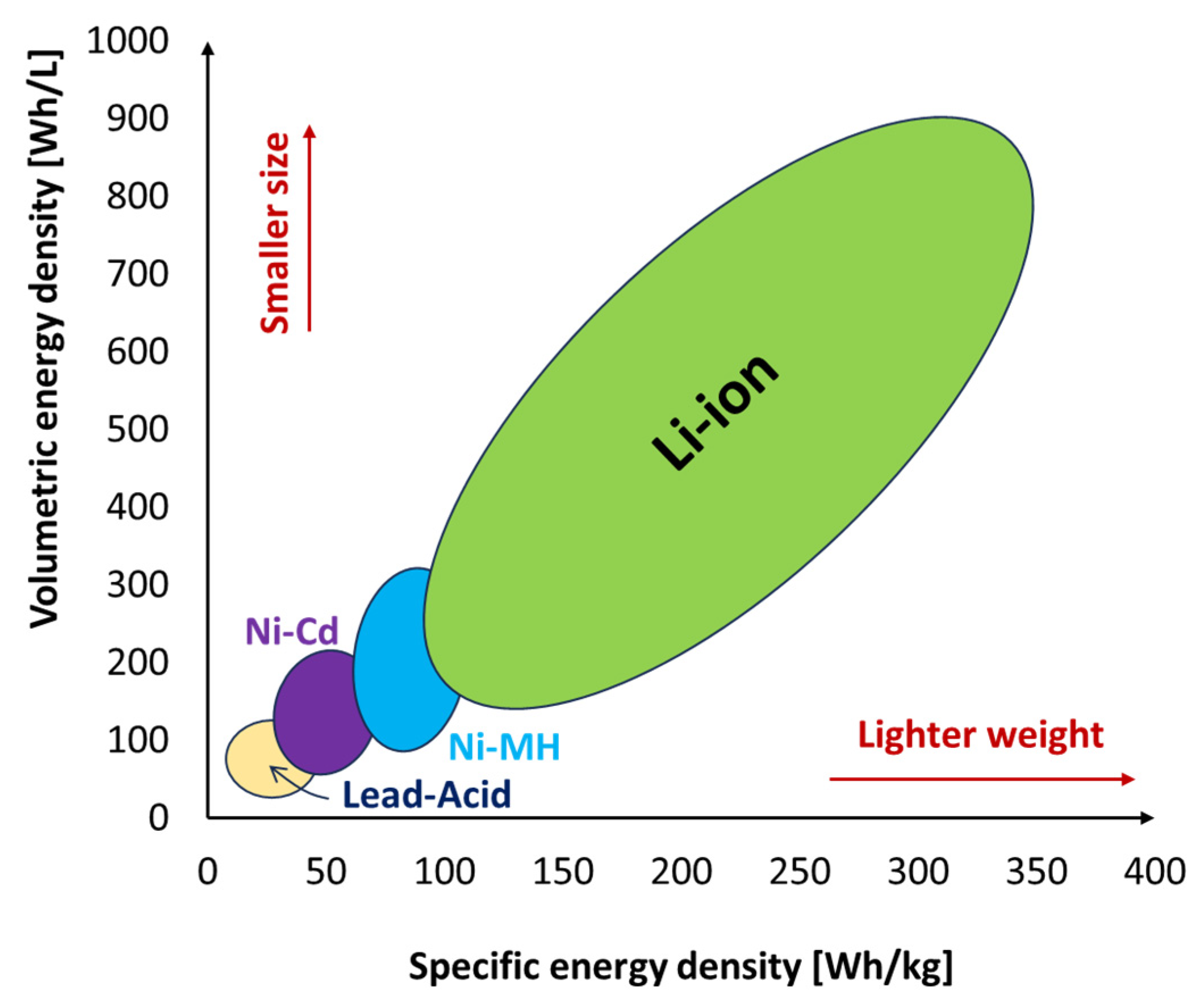
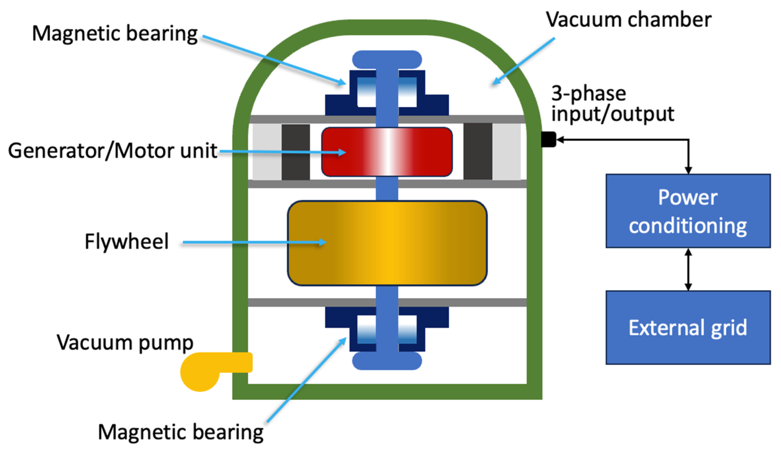
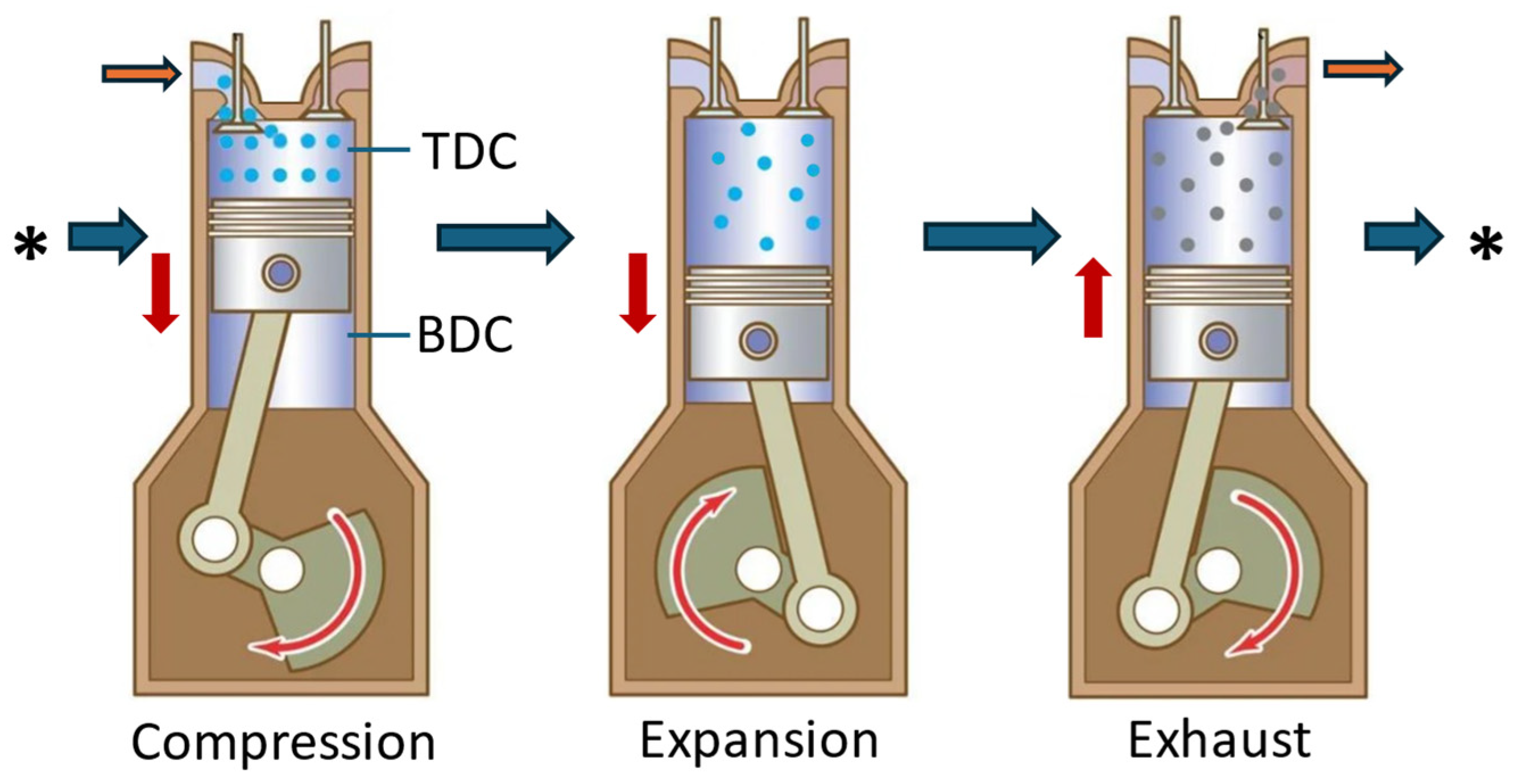
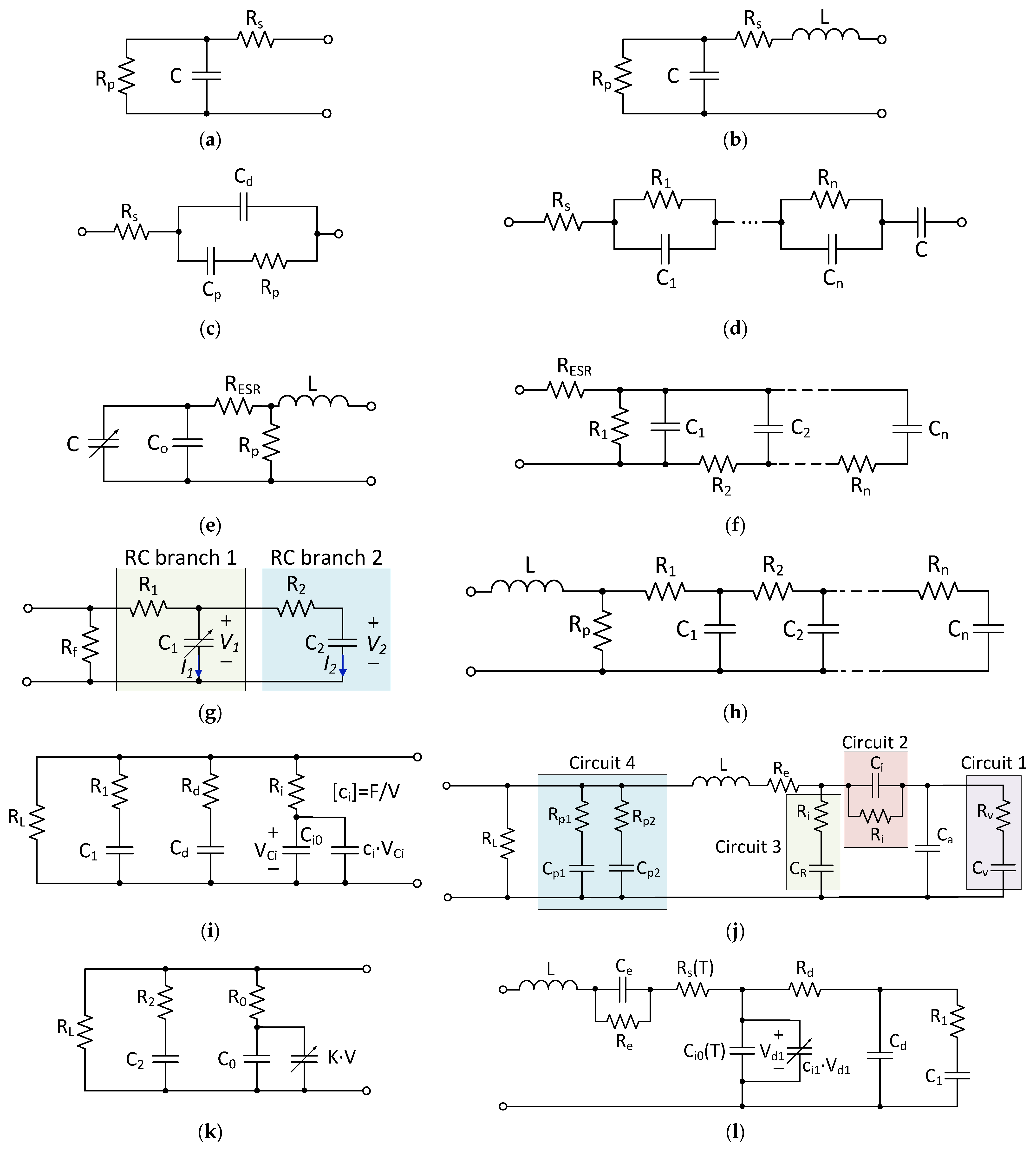
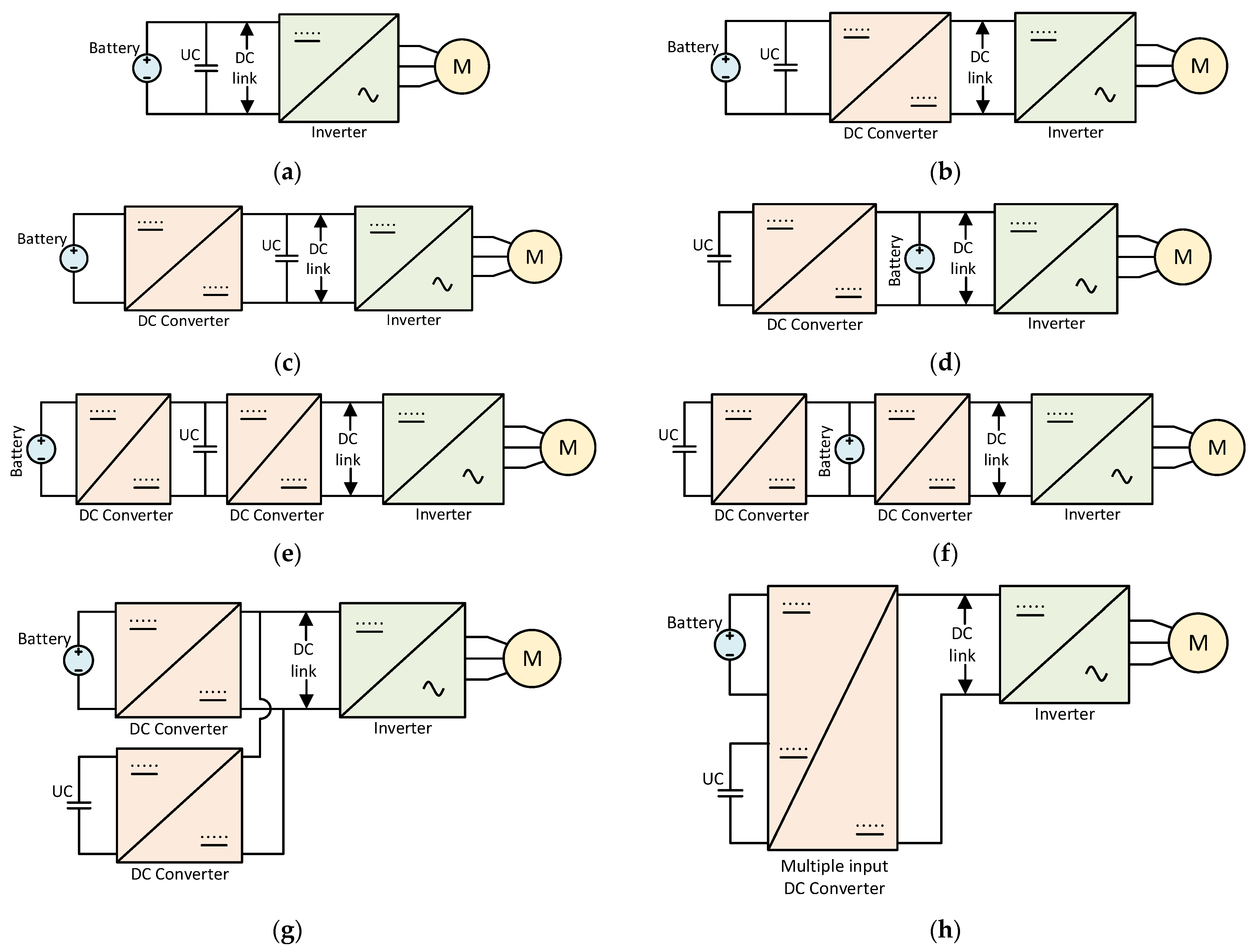
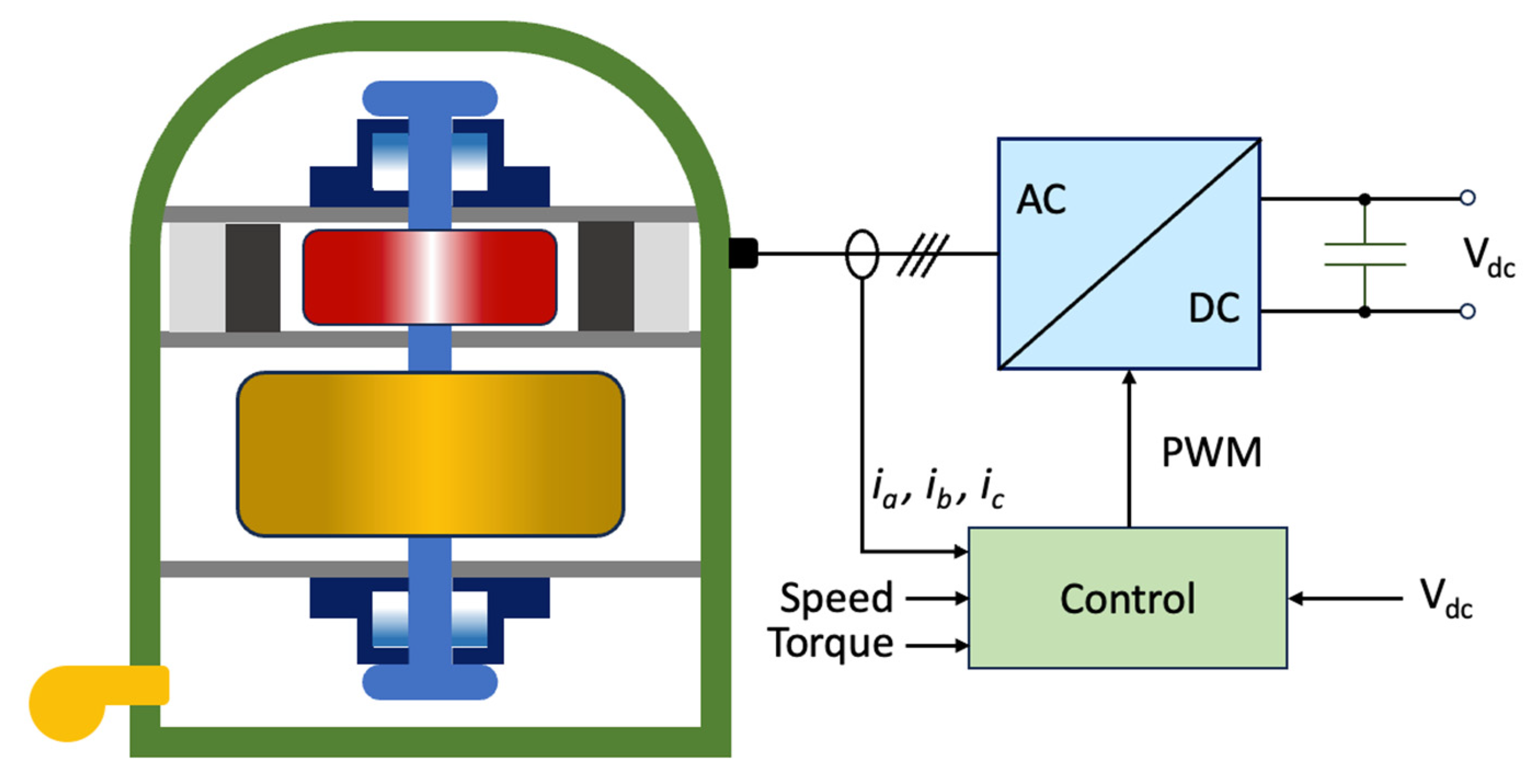
Table 1.
Technical comparison of various energy storage technologies.
| Energy Storage Type | Energy Density (Wh/kg) | Advantages | Disadvantages | References | |
|---|---|---|---|---|---|
| Battery | Lead acid | 25–50 |
|
| [57,58,59,60] |
| NiCd | 40–75 |
|
| [57,58,60] | |
| NiMH | 70–100 |
|
| [57,58,59,60] | |
| NiFe | <50 |
|
| [57,59] | |
| NiZn | 50–60 |
|
| [57,58,59] | |
| Li-ion | 150–350 |
|
| [57,58,59,60] | |
| Supercapacitor | 2–5 |
|
| [61,62] | |
| Flywheel | Low speed | <5 |
|
| [61,63] |
| High Speed | >100 | ||||
| Hydrogen storage | 33.3 × 10³ |
|
| [61,64] | |
| Compressed air storage | 20–85 |
|
| [65] | |
Disclaimer/Publisher’s Note: The statements, opinions and data contained in all publications are solely those of the individual author(s) and contributor(s) and not of MDPI and/or the editor(s). MDPI and/or the editor(s) disclaim responsibility for any injury to people or property resulting from any ideas, methods, instructions or products referred to in the content. |
© 2024 by the authors. Licensee MDPI, Basel, Switzerland. This article is an open access article distributed under the terms and conditions of the Creative Commons Attribution (CC BY) license (https://creativecommons.org/licenses/by/4.0/).
Share and Cite
MDPI and ACS Style
Nkembi, A.A.; Simonazzi, M.; Santoro, D.; Cova, P.; Delmonte, N. Comprehensive Review of Energy Storage Systems Characteristics and Models for Automotive Applications. Batteries 2024, 10, 88. https://doi.org/10.3390/batteries10030088
AMA Style
Nkembi AA, Simonazzi M, Santoro D, Cova P, Delmonte N. Comprehensive Review of Energy Storage Systems Characteristics and Models for Automotive Applications. Batteries. 2024; 10(3):88. https://doi.org/10.3390/batteries10030088
Chicago/Turabian StyleNkembi, Armel Asongu, Marco Simonazzi, Danilo Santoro, Paolo Cova, and Nicola Delmonte. 2024. "Comprehensive Review of Energy Storage Systems Characteristics and Models for Automotive Applications" Batteries 10, no. 3: 88. https://doi.org/10.3390/batteries10030088
Note that from the first issue of 2016, this journal uses article numbers instead of page numbers. See further details here.