Article

Investigating the Effect of Carbonyl Iron Powder Doping on the Microstructure and Magnetic Properties of Soft Magnetic Composites

1
Anhui International Joint Research Center for Metallurgical Processes and Systems Science, Anhui University of Technology, Ma’anshan 243002, China
2
Ansteel Guangzhou Automotive Steel Co., Ltd., Guangzhou 511434, China
*
Authors to whom correspondence should be addressed.
These authors contributed equally to this work. They are considered as co-first authors.
Magnetochemistry 2024, 10(4), 23; https://doi.org/10.3390/magnetochemistry10040023
Submission received: 20 February 2024 / Revised: 7 March 2024 / Accepted: 25 March 2024 / Published: 30 March 2024
(This article belongs to the Special Issue Advances in Soft Magnetic Materials)

Abstract

:
This study proposes the thermal decomposition of salt compounds and doping of carbonyl iron powders (CIPs) to optimize the preparation of an insulating layer through the solid-phase interface reaction. First, (Fe–Si–Cr + CIPs)/ZnSO4 composite powders were synthesized using the hydrothermal method and (Fe–Si–Cr + CIPs)/ZnO·SiO2·Cr2O3 SMCs with a ZnO·SiO2·Cr2O3 composite insulation layer were prepared through heat treatment and cold pressing. The effect of the CIP doping content on the microstructure and magnetic properties of the (Fe–Si–Cr + CIPs)/ZnO·SiO2·Cr2O3 SMCs were then investigated. During the heat treatment, ZnSO4 decomposed into solid ZnO and gaseous SO2 and O2. The O2 drives the solid-phase reaction, prompting the migration of nonmagnetic Si and Cr atoms from the interior of the Fe–Si–Cr soft magnetic powder to the surface insulation layer, finally forming the ZnO·SiO2·Cr2O3 insulation layer. The doped CIPs also show good plasticity during the coating process, combining with the coating layer to fill the internal pores of SMCs. Moreover, as the particles are small with a high surface area, they increase the number of reaction sites for ZnSO4 decomposition and facilitate the growth of the composite insulation layer, promoting its uniform distribution on the surfaces of the soft magnetic powders and CIPs. The lattice mismatch between the insulation layer and soft magnetic powder is reduced while the magnetic-phase content is increased, allowing the effective doping of CIPs sin the insulation layer. The magnetic properties of SMCs can be precisely regulated by changing the doping amount of CIPs. Unlike other insulating layer–preparation strategies based on the interfacial solid-phase reaction, the proposed method exploits the high plasticity and specific surface area of CIPs and removes the lattice mismatch between the insulation layer and soft magnetic powder.

1. Introduction

Soft magnetic composites (SMCs) composed of soft magnetic powders and insulating layers can effectively fill the vacancies of traditional laminates and ferrites. The excellent characteristics of SMCs, such as three-dimensional magnetic isotropy and high saturation magnetization, have been increasingly exploited in applications. For example, SMCs are used in electromagnetic devices such as inductors and sensors for power electronics [1,2,3]. The new economic situation has demanded the development of miniaturized, lightweight, energy-saving soft magnetic composite devices that operate at high frequency and high temperatures. Accordingly, soft magnetic composite materials with excellent comprehensive performance, especially those that improve the permeability and reduce the core loss, has become an important research direction in the magnetic materials field [4,5,6].
To achieve the above goals, researchers have explored various methods: doping with a highly permeable magnetic fine powder to enhance the magnetic coupling between magnetic particles, developing magnetic insulating media that enhance the ferromagnetic filling factor, and optimizing the heat-treatment process of soft magnetic composites to improve the crystal structure and stress state of the magnetic phase [5]. Other promising strategies are the preparation of an insulation layer [3] based on hot-pressing sintering [6] and heat-treatment processes that induce an interfacial solid-phase reaction. The performances of SMCs can be optimized by designing the surface reaction and optimizing the composition of the insulation layer. For example, Huang et al. [6] found that during hot-pressing sintering, the selective oxidation of Si by CeO2 forms a CeO2·SiO2 composite insulation layer on the surface of Fe–Si–Cr soft magnetic powder in situ. This composite insulation layer with high resistivity can effectively reduce the eddy-current loss of SMCs at midrange and high frequencies. Simultaneously, the nonmagnetic Si elements migrate to the CeO2 insulation layer, increasing the magnetic-phase content in the soft magnetic powder and increasing the permeability (from 20 to 29.8 at 500 kHz). Li et al. [3] reported that a TiO2 insulating layer on an Fe–Si–Al-based SMCs controls the oxidation of Fe–Si–Al soft magnetic powder during the heat-treatment process, allowing progressive oxygen release. In addition, the TiO2 layer becomes ferromagnetic when releasing O atoms, strictly limiting the solid-phase reaction to the interface region. This restriction electrically insulates the Fe–Si–Al soft magnetic particles while reducing the magnetic dilution effect inside the SMCs, ultimately increasing the permeability to 143 and reducing the loss to 130 kW/m3 (50 mT, 100 kHz). Although these methods have largely improved the performance optimization of SMCs, the severe lattice mismatch between the new insulation layer formed by the interfacial solid-phase reaction and the soft magnetic powder causes internal cracks in the insulation layer [3]. Therefore, the existing insulating layer–preparation strategy based on the solid-phase interface reaction must be optimized to meet the current requirements of high-permeability and low-loss SMCs.
Using Fe–Si–Cr soft magnetic powder as the substrate, the present authors optimize the preparation strategy of the insulation layer based on the solid-phase interface reaction through thermal decomposition of salt compounds and doping with carbonyl iron powders (CIPs). First, (Fe–Si–Cr + CIPs)/ZnSO4 composite powders were prepared by adding CIPs with different mass fractions during the hydrothermal coating of ZnSO4. Next, Fe–Si–Cr based SMCs were prepared through heat-treating and then cold pressing. The ZnSO4 decomposes during the powder heat-treatment process, producing O2 that reacts with the Cr and Si atoms (which have low oxygen potential) in the Fe–Si–Cr soft magnetic powder at the interface, forming a composite insulation layer of ZnO, SiO2, and Cr2O3. In addition, the CIPs dopant effectively fills the internal pores of the SMCs and reduces the magnetic dilution effect caused by the nonmagnetic insulation layer. Owing to its high specific surface area, the dopant also increases the number of reaction sites for ZnSO4 decomposition, enhancing both the solid-phase interface reaction and the growth and uniformity of the composite insulation layer distributed on the surfaces of the soft magnetic powders and CIPs. As a result, the negative effect of the lattice mismatch between the insulation layer and the soft magnetic powder is weakened. Therefore, the proposed strategy is expected to promote the preparation of fast-response SMCs with high power density for electromagnetic devices.

2. Materials and Methods

2.1. Materials

Fe–Si–Cr aerosol alloy powder (Si = 3.0 wt%, Cr = 3.67 wt%, average particle size 100 μm) produced by Jiangxi Yue’an Superfine Metal Co., Ltd. (Ganzhou, China) was used as a soft magnetic powder matrix and deionized water was used as the solvent. The precursor for the insulation coating was zinc sulfate monohydrate powder (ZnSO4·H2O, purity ≥ 99.9%) produced by Aladdin Reagent Co., Ltd. (Shanghai, China). The CIPs dopant (average particle size 500 nm, Fe ≥ 99.1 wt%) was purchased from Guangzhou Metal Metallurgy Co., Ltd. (Guangzhou, China). The protective gas for the subsequent powder heat-treatment process was high-purity argon (Ar, purity ≥ 99.99%, Nanjing Special Gas Co., Ltd., Nanjing, China). The adhesives, solvents, and lubricants for the molding process were analytical grade silicone, acetone, and zinc stearate, respectively, all purchased from Sinopod Chemical Reagent Co., Ltd. (Shanghai, China). All chemicals were of analytical grade and not further purified.

2.2. Synthesis of Fe–Si–Cr-Based SMCs

Twenty milliliters of deionized water, 3 wt% ZnSO4·H2O powder, and a specified amount of CIPs (0, 4, 8, 12, 16, or 20 wt%) were added to 100 g of Fe–Si–Cr soft magnetic powder, which had been preweighed in a beaker. The mixture was stirred in a constant-temperature water bath (70 °C) until dry and was further dried for 1 h in a vacuum drying oven, yielding the (Fe–Si–Cr + CIPs)/ZnSO4 composite powder. This powder was placed in a tubular furnace under an argon atmosphere and heated to 950 °C at 25 °C/min, where it was held for 60 min to obtain the (Fe–Si–Cr + CIPs)/ZnO·SiO2·Cr2O3 composite powder. Silicone resin (1 wt%) was dissolved and well-stirred in acetone. After adding the (Fe–Si–Cr + CIPs)/ZnO·SiO2·Cr2O3 composite powder, stirring was continued until the solvent had completely volatilized. Annular SMCs with an outer diameter of 26.9 mm, an inner diameter of 14.7 mm, and a height of 11.2 mm were then prepared under 1600 MPa at 25 °C. The sample size followed the enterprise standard (106-026A) of Zhejiang Dongmu Keda Magnetoelectric Co., Ltd. (Huzhou, China). Finally, the SMCs were placed in an argon atmosphere and annealed for 60 min at 500 °C. The warming rate was 25 °C/min.

2.3. Characterization

The phases in the Fe–Si–Cr soft magnetic powder, (Fe–Si–Cr + CIPs)/ZnSO4 composite powder, and (Fe–Si–Cr + CIPs)/ZnO·SiO2·Cr2O3 composite powder were analyzed using a Bruker D8 Advance X-ray diffractometer (Billerica, MA, USA) with copper targets, a scanning range of 10°–90°, and a scanning speed of 1°/min. The chemical bonds on the surfaces of the three powders were detected using Fourier transform infrared (FTIR) spectroscopy (Nicolet iS 10 infrared, Thermo Scientific, Waltham, MA, USA) in the range 400–1400 cm−1. The compositions and chemical valence states of the elements in the three powders were studied using X-ray photoelectron spectroscopy (XPS) (PHI-5000versaprobe, ULVAC-PHI, Chigasaki, Japan). The irradiation source was Al Kα and the binding energy range was 0–1300 eV. The surface morphologies and composition distributions of the three powders were characterized using scanning electron microscopy (SEM) (Tescan Mira3 Xmu, TESCAN, Brno, Czech Republic) with energy dispersive X-ray spectroscopy (EDS).
The Fe–Si–Cr-based SMCs were prepared by doping with different contents of CIPs (0–20 wt%) and their densities were measured using the Archimedean drainage method. The prepared SMCs were cut into 5 mm × 5 mm × 5 mm blocks and their hysteresis loops were obtained at 25 °C using an vibrating sample magnetometer (Quantum Design, San Diego, CA, USA). The test field range was ±18,000 Oe and the step size was 50 Oe. The resistivities of all SMCs were tested on a four-point probe system (RTS-8, Suzhou Lattice Electronics Co., Ltd., Suzhou, China). The permeabilities and losses of the SMCs were measured at 5–30 mT, 25–300 kHz, 40 coil turns, using an alternating current magnetic analyzer (SY-8219, IWATSU, Tokyo, Japan).

3. Results and Discussion

To comprehensively evaluate the effects of insulation coating and heat treatment on the morphologies of the composite powders, the morphologies and element distributions of the powders in the three treatment states were analyzed by SEM and EDS and are shown in Figure 1a–d. The Fe–Si–Cr soft magnetic powder exhibits a typical spherical structure and a relatively smooth surface (Figure 1a). However, the uneven cooling rate and collisions between powder particles during the process of aerosol preparation introduce microdefects such as pits and folds on the powder surface. The elemental maps revealed only Fe, Si, and Cr elements in the Fe–Si–Cr soft magnetic powder. These three elements were uniformly dispersed through the powder, indicating a uniform chemical composition of the Fe–Si–Cr soft magnetic powder with no obvious chemical segregation. Meanwhile, as shown in the SEM images and EDS results of the (Fe–Si–Cr + CIPs)/ZnSO4 composite powder (Figure 1b), the insulation coating roughened the surface without disturbing the original spherical structure of the soft magnetic powder. Further microscopic analysis revealed that the coating layer was unevenly attached, with a lamellar structure on the surface of the Fe–Si–Cr soft magnetic powder, effectively filling the microscopic defects on the powder surface. The doped CIPs are dispersed among the flaky particles and incompletely coated with ZnSO4. The EDS analysis confirmed the uniform distributions of Fe, Si, and Cr, along with new Zn, S, and O elements, in the (Fe–Si–Cr + CIPs)/ZnSO4 composite powder. As evidenced in the SEM image of the (Fe–Si–Cr + CIPs)/ZnO·SiO2·Cr2O3 composite powder, heat treatment notably changed the morphology of the coating on the powder surface. The submicron CIPs particles originally included in the flake coating layer were covered by a newly formed flocculent material and larger (micron-scale) CIPs particles were embedded in the coating layer (blue coloration in the SEM image of Figure 1c). Meanwhile, Fe, Si, Cr, Zn, and O elements were evenly distributed on the powder surface but the S element has disappeared.
Deep white, bright white, and dark gray areas were observed in the field of view of the cross-section of the (Fe–Si–Cr + CIPs)/ZnO·SiO2·Cr2O3 composite powder (Figure 1d). The dark gray area was uniformly (~1.7 μm) thick, intermingled with the bright white area, and covered a dark white area. The bright white parts were re-colored blue during the image processing to clarify their distribution. Combining the cross-sectional image with the elemental maps, the dark white and dark gray areas were identified as the Fe–Si–Cr soft magnetic powder and the coating layer, respectively. It was inferred that the bright white particles between the dark gray cladding layer and the dark white Fe–Si–Cr soft magnetic powder embedded in the outer edge of the dark gray cladding layer were CIPs that were uncoated before the heat treatment. Wang et al. [4] showed that by virtue of its high reactivity and large specific surface area, CIPs provide additional reaction sites for the decomposition reaction of ZnSO4 during the hydrothermal coating process, promoting the growth of reaction products on the surfaces of the Fe–Si–Cr soft magnetic powders and CIPs. The absence of S in the cross-section of the (Fe–Si–Cr + CIPs)/ZnO·SiO2·Cr2O3 composite powder is possibly explained by volatilization of SO2, the decomposition product of ZnSO4, during the heat treatment process. The reaction mechanism and specific composition of the heat-treated insulation layer will be further explored.
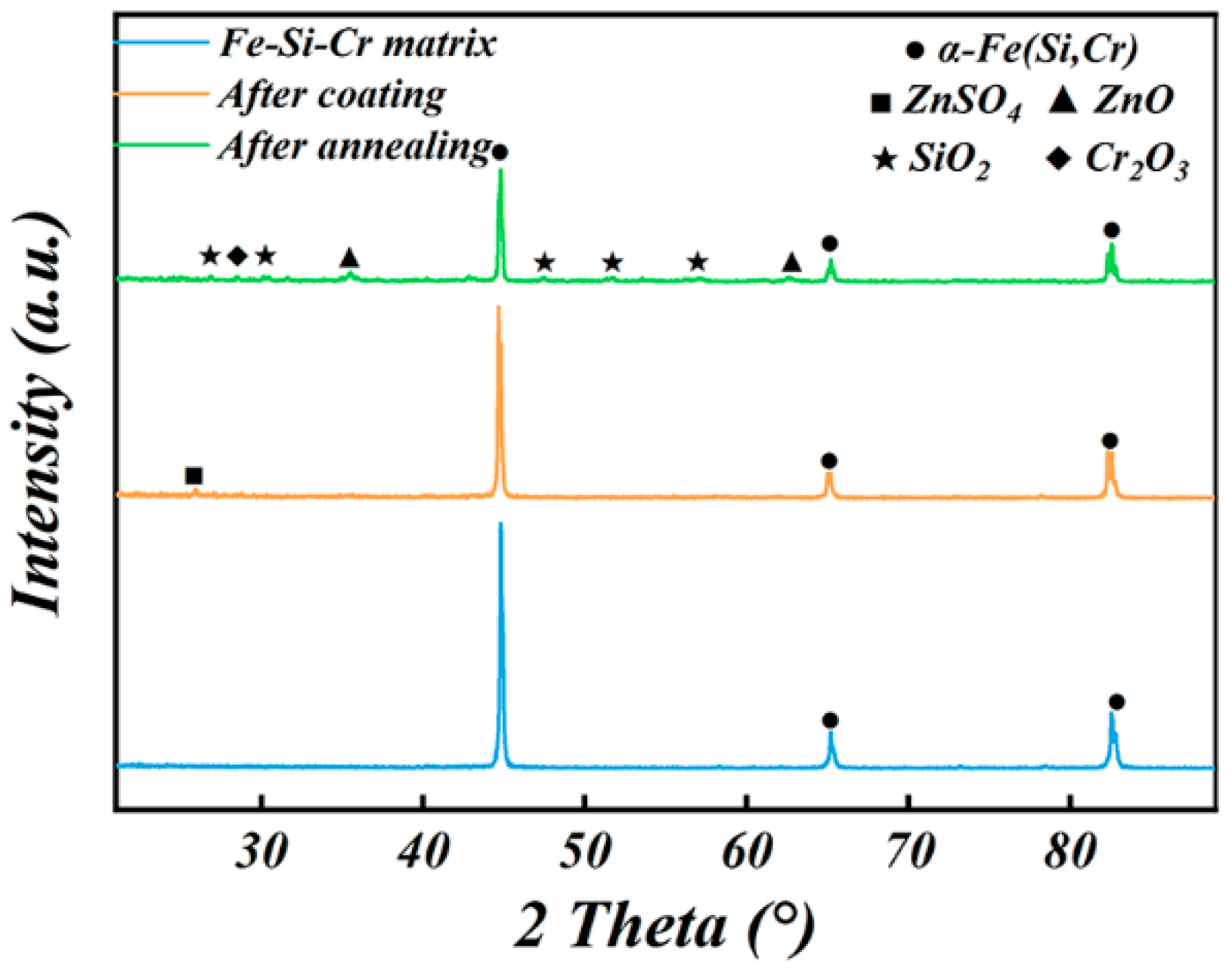
To study the effects of the coating process and heat treatment on the phase composition of the composite powder, the phases of the powders in the different treatment states were determined from XRD patterns of the powders. The XRD pattern of the Fe–Si–Cr soft magnetic powder exhibited three distinct diffraction peaks at 2θ = 44.8°, 65.2°, and 82.5°, corresponding to the (110), (200), and (211) crystal faces of the body-centered cubic α-Fe(Si,Cr) phase, respectively (Figure 2). These peaks were consistent with the ICSD standard card No. 01-087-0722. The XRD pattern of the (Fe–Si–Cr + CIPs)/ZnSO4 composite powder (with the insulation coating) shows an additional diffraction peak at 2θ = 26.2°, which is attributed to the (020) crystal face of the ZnSO4 phase (ICDD No.00-001-1075). Meanwhile, in the XRD pattern of the (Fe–Si–Cr + CIPs)/ZnSO4 composite powder after heat treatment, the original ZnSO4 diffraction peaks disappeared and were replaced with a series of new diffraction peaks at 2θ = 26.8°, 30.4°, 47.5°, 51.7°, and 57.0°, associated with SiO2 (ICSD Card No.01-078-1254), along with a diffraction peak of Cr2O3 at 2θ = 28.5° (ICSD Card No.01-089-2806) and diffraction peaks of ZnO at 35.6° and 62.5° (ICSD Card No.01-079-0208). Next, the full width at half maximum of the diffraction peak of the (110) crystal plane in the α-Fe(Si,Cr) phase was analyzed in the three powder samples. The α-Fe(Si,Cr)-phase (110) diffraction peak of the (Fe–Si–Cr + CIPs)/ZnO·SiO2·Cr2O3 composite powder presented a smaller full width at half maximum (0.197°) than that of the Fe–Si–Cr soft magnetic powder (0.227°) and (Fe–Si–Cr + CIPs)/ZnSO4 composite powder (0.223°). This result shows that the heat treatment-induced solid-phase reaction coordinated with CIP doping, effectively reducing the internal stress and weakening the malignant effect of lattice mismatch between the coating layer and the soft magnetic powder. These improvements are crucial for subsequently optimizing the magnetic properties of the Fe–Si–Cr soft magnetic composites.
The surface compositions of the three powders were determined from the FTIR measurements (Figure 3). The absorption peaks at 598 and 1080 cm−1 in the spectra of all powder samples corresponded to tensile vibrations of Fe–O [7] and O–Si–O [8] and asymmetric tensile vibrations of Si–O [9], respectively, indicating that the surface adsorbed water in the powder was slightly oxidized during the detection process. The FTIR spectrum of the (Fe–Si–Cr + CIPs)/ZnSO4 composite powder showed absorption peaks at 825, 1009, and 1133 cm−1, corresponding to vibrations of the V4 group of SO42− [10], tensile vibrations of S–O [11], and global vibrations of SO42− [12], respectively. In the FTIR spectrum of the (Fe–Si–Cr + CIPs)/ZnO·SiO2·Cr2O3 composite powder, the absorption peak of ZnSO4 disappeared while the absorption peak of the Si–O–Si rocking mode emerged at 445 cm−1 [9]. The absorption peaks at 481 and 909 cm−1 corresponded to stretching vibrations of Zn–O [13,14] and Cr–O [15], respectively.
Panels (a) and (b) of Figure 4 show the XPS results of the Fe–Si–Cr soft magnetic powder, (Fe–Si–Cr + CIPs)/ZnSO4 composite powder, and (Fe–Si–Cr + CIPs)/ZnO·SiO2·Cr2O3 composite powder. The corrected peaks of Fe2p (Figure 4a) and O1s (Figure 4b) were obtained by curve fitting, setting the electron binding energy of the C–C orbital peak at 284.8 eV. The Fe2p XPS spectrum of the Fe–Si–Cr soft magnetic powder can be divided into Fe0 (707.2 eV, 2.1 at%) and Fex+ (710.8 eV, 97.9 at%). The binding energy of Fe0 slightly exceeded the standard binding energy (706.5 eV) because the Si and Cr elements interacted with Fe [16,17]. In the (Fe–Si–Cr + CIPs)/ZnSO4 composite powder, the atomic percentage of Fe0 increased to 6.2 at% and the binding energy peak moved to 706.6 eV. The atomic percentage of Fe0 in (Fe–Si–Cr + CIPs)/ZnO·SiO2·Cr2O3 decreased to 1.7 at% and the peak position of the binding-energy moved to 707.1 eV. It was surmised that CIPs increased the Fe0 content on the (Fe–Si–Cr + CIPs)/ZnSO4 surface but the subsequent heat treatment decomposed the ZnSO4 and induced the growth of subsequent products on the Fe–Si–Cr soft magnetic powder and CIPs surfaces. Eventually, these products covered the CIPs originally embedded in the insulation layer, reducing the Fe0 content on the (Fe–Si–Cr + CIPs)/ZnO·SiO2·Cr2O3 composite powder surface. In the O XPS spectrum of the Fe–Si–Cr soft magnetic powder, the binding energy peaks at 530.7 and 531.4 eV corresponded to the O element in Cr2O3 and SiO2, respectively, accounting for 32.4 and 67.6 at%, respectively. In the O XPS spectrum of the (Fe–Si–Cr + CIPs)/ZnSO4 composite powder, the binding energy peak at 533.8 eV corresponded to the O element of SO42− (26.8 at%). This peak was absent in the XPS results of the (Fe–Si–Cr + CIPs)/ZnO·SiO2·Cr2O3 composite powder, being replaced with a new binding energy peak at 530.1 eV corresponding to O in ZnO (accounting for 11.3 at%). Meanwhile, the binding energy peaks of O in Cr2O3 and SiO2 were retained (530.7 eV, 59.4 at%; 531.4 eV, 29.6 at%).
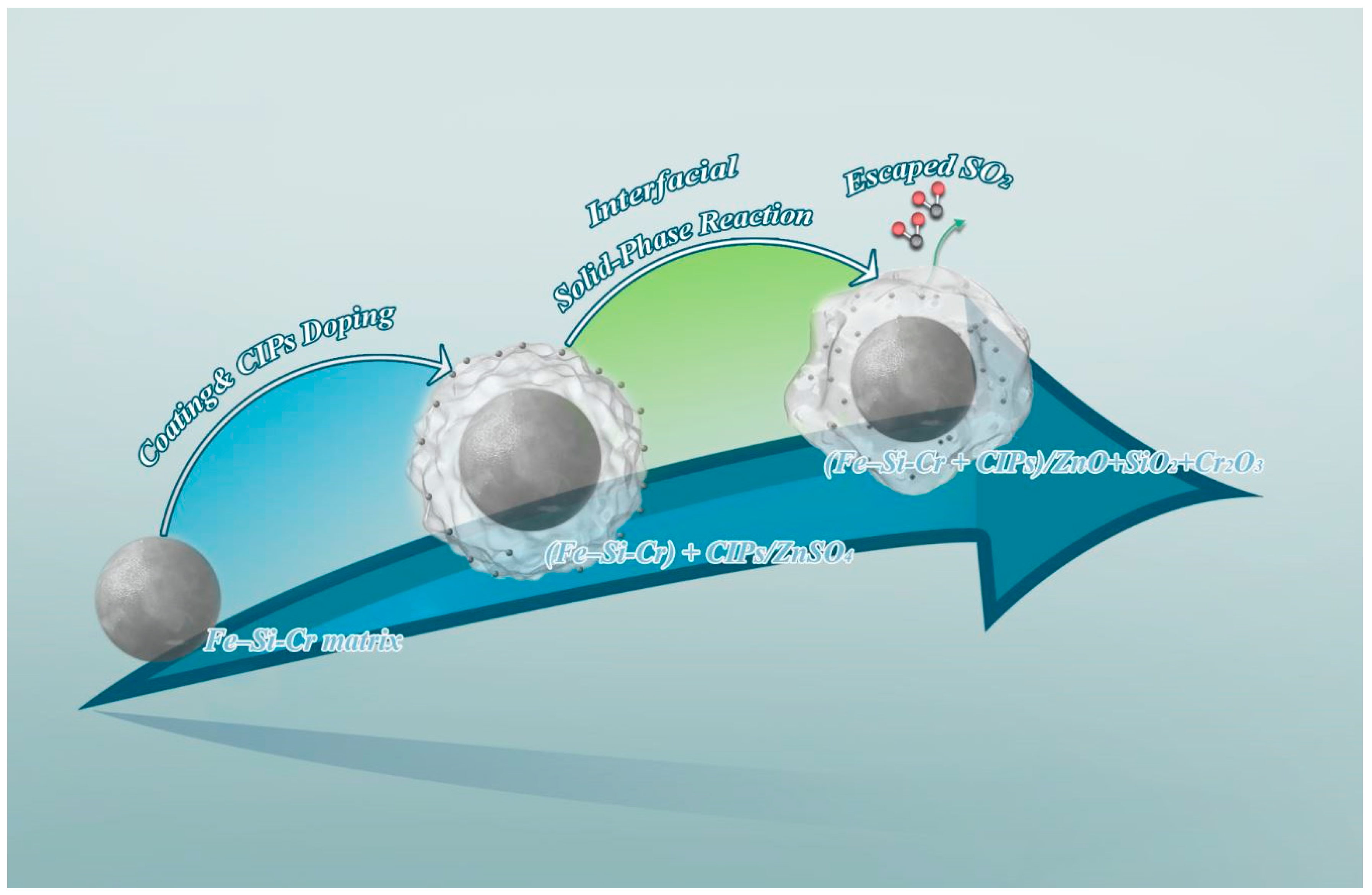
Based on the above analysis and a previous report [12], the formation mechanism of the ZnO·SiO2·Cr2O3 composite insulation layer on the surface of the Fe–Si–Cr soft magnetic powder was inferred as follows. The results are shown in Figure 5. During heat treatment at 950 °C, the ZnSO4 coating on the Fe–Si–Cr surface decomposed, releasing gas-phase SO2 and O2. The ZnO decomposition product was continually coated on the volume surfaces SiO2 and Cr2O3. The specific reaction process is shown in Formulas (1)–(3):
2ZnSO4 (s) → ZnO (s) + SO2 (g) + O2 (g)
Si (s) + O2 (g) → SiO2 (s)
4Cr (s) + 3O2 (g) → 2Cr2O3 (s)
The volatilization of SO2 decreased the S content on the surface. Simultaneously, the generated O2 could oxidize the low-oxygen-potential Si and Cr elements at the interface of the Fe–Si–Cr soft magnetic powder, promoting the migration of Si and Cr elements from the surface of the soft magnetic powder to the surface of the coating layer. Ultimately, a composite insulation layer of ZnO, SiO2, and Cr2O3 was formed. Meanwhile, the small CIPs particles with a large specific surface area provided numerous growth sites for solid-phase reaction products, facilitating the uniform distribution of the insulation layer on the surface of the ferromagnetic phase and reducing the internal stress of the insulation layer. Therefore, the heat-treatment process grew an insulation layer composed of three solid-phase products (ZnO, SiO2, and Cr2O3) on the surfaces of the Fe–Si–Cr soft magnetic powder and small-sized CIPs particles, ensuring insulation between both the Fe–Si–Cr soft magnetic powder particles and the CIP particles. Heat treatment also guaranteed the integrity and uniformity of the insulation layer. This structure effectively weakened the adverse effects of lattice mismatch, enabling subsequent improvement in the magnetic properties of the composites.
Based on the above analysis, the authors explored the effects of the CIP doping amount (0, 4, 8, 12, 16, and 20 wt%) on the internal morphology and magnetic properties of the SMCs. Panels (a)–(f) of Figure 6 show the cross-sectional morphologies of the SMCs doped with different CIP amounts. These images were acquired in SEM backscattering mode, in which the intensity of the electron emissions scattered from different elements increased with increasing atomic number, giving rise to three color contrasts. The white spherical areas (corresponding to the Fe–Si–Cr soft magnetic powder and CIPs) were surrounded by gray areas corresponding to the insulation layer, whereas the black areas represented the pores between the powders. In the SMCs without CIPs, the internal coating layer was unevenly distributed, the Fe–Si–Cr soft magnetic powder particles were in close contact, and many pores appeared at the junctions of different particles. The loss of the insulation layer was possibly attributable to lattice mismatch between the soft magnetic powder and the insulation layer during the high-pressure molding process. As the doping amount of CIPs increased from 4 to 16 wt%, the coating layer gradually distributed uniformly along the outer edge of the Fe–Si–Cr soft magnetic powder particles, and the pores between the powder particles were gradually filled by small particles and CIP particles coated by the insulation layer. The pores of the 16 wt% doped Fe–Si–Cr-based SMCs were almost completely filled with small CIP particles, and direct contact between these small particles was blocked by the gray insulation layer. This observation proves that heat-treating the powder promotes the growth of the insulation layer on the surfaces of the small CIPs particles, ensuring insulation between the Fe–Si–Cr soft magnetic powders and CIPs. However, when the doping amount increased to 20 wt%, the excessive CIPs made direct contact. In Figure 6f, the coating layer and CIPs are aggregated and the pores are reformed. This phenomenon can be explained by changes in density.
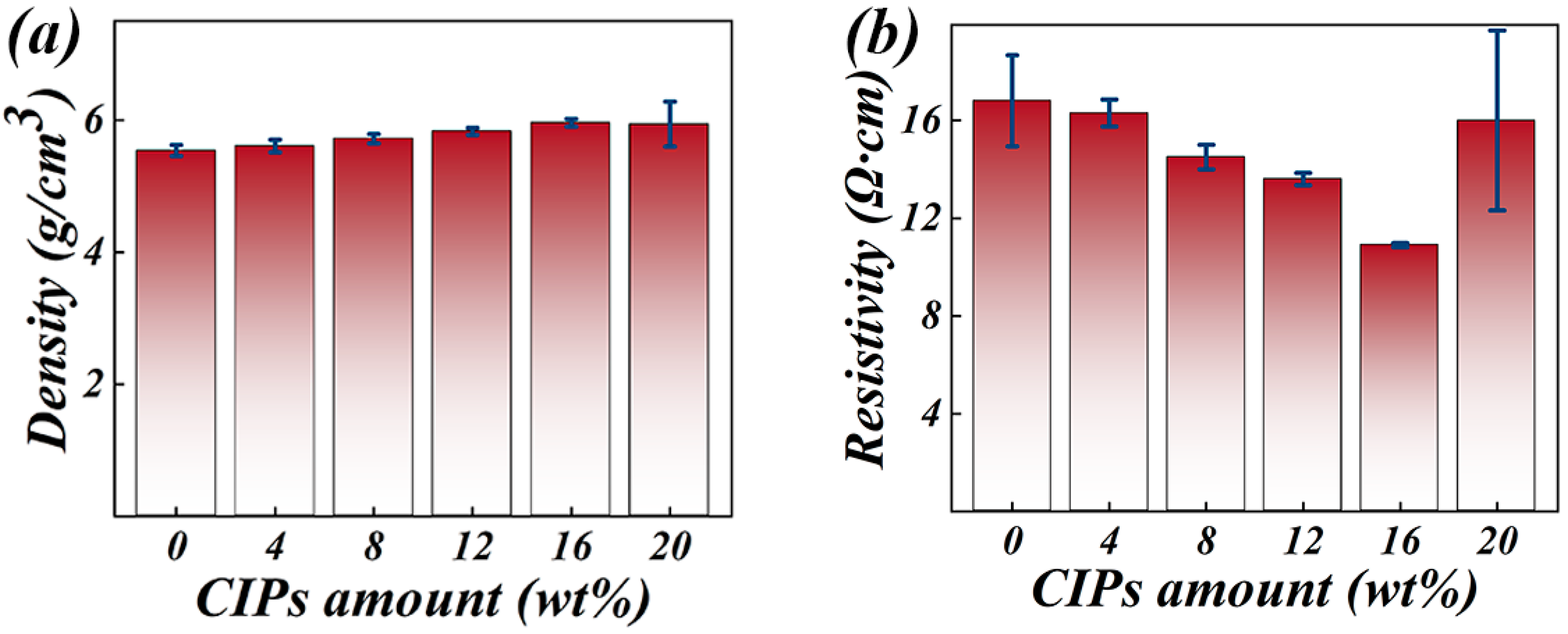
Figure 7a shows the effect of the CIP doping amount on SMCs’ density. As the CIP doping amount increased from 0 to 16 wt%, the density of the Fe–Si–Cr-based SMCs increased from 5.54 to 5.96 g/cm3 because the CIPs were highly plastic and combined with the insulation layer, improving the compressibility of composite powders in which the pores in the SMCs were completely filled, thereby increasing density. When the doping amount increased to 20 wt%, direct contact between the CIPs particles deteriorated the fluidity of the composite powder, resulting in agglomeration and the formation of new pores during the molding process. Accordingly, the increasing trend of SMCs’ density is slowed.
In the service environments of practical applications, the insulation characteristics of SMCs strongly determine the SMCs’ properties. Therefore, resistivity is a key indicator of insulation performance and its change trend is worthy of investigation. As the doping amount of carbonyl iron powder increased from 0 to 16 wt%, the resistivity of the SMCs gradually decreased from 16.8 to 10.9 Ω·cm (Figure 7b). The heat treatment achieved uniform distribution of the insulation layer on the CIPs’ surfaces, and the propagation resistance of the current in the SMCs was further improved by interlayer and vibration scattering in the composite insulation layer. However, after doping with low-resistivity CIPs, the elimination of pores made the energy obtained by the external electric field carriers easily overcome the well barrier and pass from the interface region into the transition region. Therefore, the number density and mobility of carriers improved, the blocking effect of the insulation layer on the conductive network formed by the soft magnetic powder weakened, and the resistivity lowered [18]. At the highest doping rate (20 wt%), the CIPs particles aggregated and the irregularly distributed high-resistivity pores were reformed, thereby increasing the resistivity. In addition, the reformed pores increased the standard deviation of the resistivity. The resistivity increased when the SMCs contained pores and decreased when CIPs were added in excess.
Figure 8 shows the hysteresis loops of the Fe–Si–Cr-based SMCs doped with different CIPs contents at 25 °C. All samples exhibited good soft magnetic properties, including easy magnetization at room temperature, high saturation magnetization, and relatively low coercivity. To compare the saturation magnetization results of these SMCs in detail, the hysteresis loops in the 14,000–18,000 Oe range are magnified in Figure 8b. The saturation magnetization increased as the dopant amount increased from 0 to 16 wt%, reaching a maximum of 188.8 emu/g in the 16 wt%-doped Fe–Si–Cr-based SMCs. When the CIPs doping amount increased to 20 wt%, the saturation magnetization reduced to 180.7 emu/g because CIPs were introduced as a ferromagnetic phase (with a typical saturation magnetization range of 190–205 emu/g). The ferromagnetic phase increased the magnetic moment content per unit volume and encouraged coherent rotations of the magnetic moments during the magnetization process. For this reason, the saturation magnetization increases by 3.6% to 13.2% as the CIPs dopant amount increases from 4 to 16 wt% [19]. When the CIP doping amount reaches 20 wt%, the excessively numerous small particles agglomerate during the molding process, resulting in delamination of the coating layer and the formation of nonmagnetic-phase pores. A nonmagnetic phase is known to increase the magnetic dilution effect, impeding the free movement of magnetic moments during the magnetization process [20,21]. Therefore, increasing the doping amount to 20 wt% reduces the saturation magnetization by 4.4% from that of the 16 wt%-doped Fe–Si–Cr-based SMCs.
In Figure 9, the frequency-dependent effective permeabilities of the Fe–Si–Cr-based SMCs doped with different CIPs amounts are plotted. All SMCs show a frequency-stable initial permeability, which first increased and then decreased with an increasing CIP doping amount. The permeability was maximized (at 37.6) in the 16 wt%-doped Fe–Si–Cr-based SMCs and dropped to 28.5 in the 20 wt%-doped Fe–Si–Cr-based SMCs. Increasing the CIP doping amount improved the compressibility of the composite powders and reduced the internal stress of the SMCs. As introduced as a ferromagnetic phase, the CIPs also increased the magnetic moment per unit volume in the SMCs, facilitating magnetization of the SMCs under an applied magnetic field. Meanwhile, the CIP distribution in the insulation layer indirectly reduced the area, energy, and movement resistance of the domain walls. Therefore, the permeability increased as the doping amount increased from 4 to 16 wt%, as similarly reported by Liu et al. [22] and Zhu et al. [9]. When the doping amount further increased to 20 wt%, the direct contact between CIPs during molding process may result in the delamination of the coating layer and the re-formation of internal pores in SMCs. Consequently, the conduction efficiency of the magnetic circuit is reduced, the internal demagnetizing field is expanded, the domain-wall movement is limited, and the magnetic flux is scattered [23,24]. These processes reduce the permeability of the SMCs.
Figure 10a shows the total loss (Ptotal-cv) distributions of the Fe–Si–Cr-based SMCs doped with different amounts of CIPs. Regardless of doping content, the total loss monotonically increased with increasing frequency and field strength but increased and then decreased with increasing CIPs doping amount. At 30 mT and 200 kHz, the total loss was 1075.6 kW/m3 in the undoped SMCs, decreasing to 745.6 kW/m3 in the 16 wt%-doped SMCs. The total loss of the 20 wt%-doped SMCs reached 900.9 kW/m3. According to classical Bertotti loss-separation theory [25], Ptotal-cv can be divided into three losses—the hysteresis loss Physt, the eddy-current loss Pec, and the residual loss Pexc:
Ptotal-cv = Physt + Pec + Pexc
The hysteresis loss Physt is caused by the lagged response of the magnetic-moment direction to a change in the magnetic field direction, which causes energy dissipation during the magnetization process. The hysteresis loss is obtained by multiplying the area under the quasistatic hysteresis loop by the frequency:
P hyst = C h y s t   B m α f
The eddy-current loss Pec is mainly sourced from the heat generated in the material by the eddy current and the capacitance effect of SMCs. The resulting energy loss depends on the height, density, and other parameters of the soft magnetic composite core:
P ec = π 2 d e f f 2   B m 2 f 2 / ( 6 / [ 1 0.633 ( w / h ) tan h ( 1.58 h / w ) ) ρ s + π 2 d 2 B m 2 f 2 / 20 ρ p
The residual loss Pexc is calculated as
P exc = C exc   B m x f y
In Equations (4)–(6), Chyst is the hysteresis coefficient, Bm is the magnetic field strength, f is the frequency, and α is the fitting coefficient (typically between 1.6 and 2.2 for soft magnetic materials) [26]. deff is the effective eddy-current size, w and h represent the length and width of the magnetic circuit, respectively, and ρs and ρp are the resistivities of the soft magnetic composite core and soft magnetic powder, respectively. First, the Pcv/f versus f curves under different maximum magnetic-induction intensities are fitted to a polynomial curve. The obtained fitting curve is then extrapolated to the zero-frequency point to obtain the intercept of the hysteresis loss under quasistatic conditions. Next, the quasistatic hysteresis losses under different external field conditions are fitted to obtain the Chyst and α values. After calculating the eddy-current loss using Equation (6), the fitting parameters are substituted into Equation (7) to obtain the fitting parameters Cexc, x, and y.
To further explore the influence of CIPs doping amount on the loss, the results after loss separation were analyzed and are plotted in Figure 10b–d. Increasing the doping amount of CIPs (a material with high ferromagnetism) improves the density of SMCs, eliminates the obstruction of pores and impurities to the magnetic-circuit operation, and increases the ferromagnetic filling factor of the SMCs (Figure 10b). Simultaneously, the obstruction of the domain-wall movement is alleviated by the gradually distributed uniform insulation layer on the CIPs’ surfaces. The combined action of these two effects reduces the hysteresis loss [27]. However, excessively doped CIPs induce pore formation. According to Marrow’s research [28], introduced pores are nonmagnetic phases that break the continuity of the magnetic circuit [28], increasing the magnetic-circuit length and the hysteresis losses.
The eddy-current losses in the SMCs first increase and then stabilize with increasing CIPs doping amount (Figure 10c). This behavior can be explained by the increases in number density and mobility of carriers after adding CIPs, which weaken the limiting effect of the insulation layer on the eddy current between particles and reduce the block resistivity. According to Equation (3), the eddy-current loss gradually increases with decreasing resistivity. As the CIPs doping amount increases, the pores formed by CIPs agglomeration reduce the flow area of eddy currents in the SMCs, limiting the eddy-current operation among the soft magnetic powder particles, and the upward trend of eddy-current loss is restrained [29,30]. In addition, the residual loss is relatively low and its change mechanism differs from those of the hysteresis and eddy-current losses (Figure 10d). The residual loss is mainly sourced from the magnetic aftereffect at low frequencies and from domain-wall resonance at midrange and high frequencies. In the present study, the Pexc of SMCs was lower after CIPs doping than before doping.
Table 1 lists the optimized magnetic properties of SMCs achieved by researchers through solid-phase interface reactions in recent years. The permeabilities and loss indices of our SMCs were evaluated under the same test conditions (30 mT and 50 kHz) to ensure an accurate cross-comparison. As the solid-phase interface reaction induces the in situ growth of the surface insulation layer on the Fe–Si–Cr soft magnetic powder, the proposed process achieved CIP doping fills the internal pores of SMCs, and ensures a uniformly distributed insulation layer on the powder surface. The proposed process also weakens the negative effects of the lattice mismatch between the insulation layer and the soft magnetic powder. Therefore, both the permeability and loss are considerably improved from those in other studies. Our research team is convinced that CIPs doping can optimize the existing strategies for preparing insulators through solid-phase interface reactions and can potentially realize electromagnetic devices with fast response and high power density. In particular, the proposed method promises to improve the material properties and expand the application range of soft magnetic composites.

4. Conclusions

This study proposed an insulating layer–preparation strategy that optimizes the solid-phase interface reaction, yielding (Fe–Si–Cr + CIPs)/ZnO·SiO2·Cr2O3 SMCs with a ZnO–SiO2–Cr2O3 composite insulating layer. The formation mechanism of the composite insulation layer, the morphological changes of the doped CIPs during heat treatment, and the influence of CIPs doping amount on the internal structures and magnetic properties of the SMCs were investigated. The main conclusions are outlined below.
(1) During heat treatment, ZnSO4 coated on the powder surface via the hydrothermal method decomposes into solid ZnO and gas-phase SO2 and O2. The released O2 drives the solid-phase reaction, prompting migration of the nonmagnetic Si and Cr atoms from the interior of the Fe–Si–Cr soft magnetic powder to the surface insulation layer, finally forming a composite insulation layer of ZnO, SiO2, and Cr2O3 on the surface of the soft magnetic powder.
(2) Doping with 16 wt% CIPs optimizes the magnetic properties of the SMCs, increasing the saturation magnetization and permeability to 188.8 emu/g and 37.6 (at 10 mT), respectively, and reducing the loss to 745.6 kW/m3 (30 mT, 200 kHz). After CIP doping, the magnetic properties of the SMCs prepared by the solid-phase interface reaction are significantly improved from those of earlier studies.
(3) Unlike other insulating layer–preparation strategies based on the interfacial solid-phase reaction, this study exploits the high plasticity and large specific surface area of CIPs, thereby increasing the magnetic-phase content, reducing the losses, and improving the permeability in SMCs. The CIPs dopant also increases the number of reaction sites for ZnSO4 decomposition and growth of the composite insulation layer. Because the insulation layer is uniformly distributed on the surfaces of the soft magnetic powders and CIPs, its internal stress is lowered and the negative impact of the lattice mismatch between the insulation layer and the soft magnetic powder is weakened.
Therefore, the proposed process can not only supplement the preparation of insulation materials via the interfacial solid-phase reaction, but can potentially realize the design and optimization of SMCs with fast response and high power density.

Author Contributions

Y.L. (Yang Liu): writing—original draft, formal analysis; R.W.: investigation; K.L.: formal analysis; R.C.: methodology; Z.W.: review, editing and project administration; Y.L. (Yang Li): resources and data curation. All authors have read and agreed to the published version of the manuscript.

Funding

The authors acknowledge the financial support from the Chinese National Science Foundation (52274311), Scientific Research Planning Project of Anhui Province (2022AH040054), Outstanding Youth Project of Anhui Province (2023AH030028), Key Research and Development Plan of Anhui Province (202104b11020007), Anhui Special Support Plan (T000609), Distinguished Professor of the Wanjiang Scholars project and Anhui Province major industrial innovation plan (AHZDCYCX-LSDT2023-01).

Data Availability Statement

Derived data supporting the findings of this study are available from the corresponding author upon reasonable request.

Acknowledgments

The authors would like to thank Chao Wang and Lei He from the Shiyanjia Lab (www.shiyanjia.com, accessed on 1 January 2024) for the XRD and XPS analyses.

Conflicts of Interest

Author Yang Li was employed by the company Anstell Guangzhou Automotive stell Co., Ltd. The remaining authors declare that the research was conducted in the absence of any commercial or financial relationships that could be construed as a potential conflict of interest.

References

  1. Zhang, J.; Dong, Y.; Li, Y.; Yang, L.; Jia, X.; Zhang, L.; Cai, L.; He, A.; Li, J.; Liu, X.; et al. The effect of phosphate/TiO2 composite insulating layer on the high frequency magnetic properties of FeSiBPCNbCu nanocrystalline soft magnetic powder cores. Mater. Today Commun. 2024, 38, 107809. [Google Scholar] [CrossRef]
  2. Zhou, B.; Dong, Y.; Chi, Q.; Zhang, Y.; Chang, L.; Gong, M.; Huang, J.; Pan, Y.; Wang, X. Fe-based amorphous soft magnetic composites with SiO2 insulation coatings: A study on coatings thickness, microstructure and magnetic properties. Ceram. Int. 2020, 46, 13449. [Google Scholar] [CrossRef]
  3. Li, H.; Bai, G.; Zhao, R.; Yang, H.; Lu, Z.; Cheng, M.; Su, R.; Bandaru, S.; Zhang, Y.; Liu, X.; et al. High-performance FeSiAl soft magnetic composites achieved by confined solid-state reaction. Acta Mater. 2023, 255, 119102. [Google Scholar] [CrossRef]
  4. Wang, B.; Zhang, Z.; Shen, J.; Tian, Y.; Wang, B.; Cai, L.; Liu, L.; Yu, Y.; Wang, G. Mechanism of adding carbonyl iron powder to enhance the magnetic properties of Fe-Si-B-Cu-Nb nanocrystalline soft magnetic composites. J. Alloys Compd. 2024, 972, 172812. [Google Scholar] [CrossRef]
  5. Huang, H.; Wang, R.; Li, K.; Dai, B.; Wu, Z.; Li, G.; Lyu, P. Fabrication of high-performance FeSiCr-based soft magnetic composites using thermal decomposition of salt compounds. J. Mater. Res. Technol. 2024, 29, 3291. [Google Scholar] [CrossRef]
  6. Huang, H.; Wang, J.; Cui, Z.; Gao, Z.; Huang, Z.; Wu, Z. Selective oxidation of rare metal oxide insulation layers on particle substrates for optimizing the performance of Fe–Si–Cr-based soft magnetic composites. Mater. Des. 2023, 230, 111984. [Google Scholar] [CrossRef]
  7. Song, W.; Zhang, D.; Sun, Z.; Han, B.; He, L.-J.; Wang, X.; Lei, Q.-Q. Preparation and characterization of multiferroic BiFeO3. In Proceedings of the 2012 IEEE 10th International Conference on the Properties and Applications of Dielectric Materials, Bangalore, India, 24–28 July 2012; IEEE: New York, NY, USA, 2012; pp. 1–4. [Google Scholar]
  8. Alomairy, S.; Al-Buriahi, M.S.; Wahab, E.A.A.; Sriwunkum, C.; Shaaban, K. Synthesis, FTIR, and neutron/charged particle transmission properties of Pb3O4–SiO2–ZnO–WO3 glass system. Ceram. Int. 2021, 47, 17322. [Google Scholar] [CrossRef]
  9. Zhu, Z.; Wang, P.; Liu, J.; Lan, P.; Pang, J.; Zhang, J. Magnetic property regulation and mechanism analysis of FeSiBC soft magnetic composites by mixing with Fe–Si–Cr or carbonyl iron powder. J. Magn. Magn. Mater. 2023, 588, 171413. [Google Scholar] [CrossRef]
  10. Amarasekara, A.S.; Opoku, G.; Qiu, X.; Doctor, V. Effect of oversulfation on the chemical and biological properties of chondroitin-6-sulfate. Carbohydr. Polym. 2007, 68, 116. [Google Scholar] [CrossRef]
  11. Pan, W.; Wang, Y.; Zhao, X.; Zhao, Y.; Liu, X.; Xuan, J.; Wang, H.; Leung, D.Y.C. High-Performance Aqueous Na–Zn Hybrid Ion Battery Boosted by “Water-In-Gel” Electrolyte. Adv. Funct. Mater. 2021, 31, 2008783. [Google Scholar] [CrossRef]
  12. Wei, X.L.; Gao, M.G.; Liu, J.G.; Xu, L. Quantification of sulphate in ambient aerosols by FTIR spectroscopy. Adv. Mater. Res. 2013, 718, 1136. [Google Scholar] [CrossRef]
  13. Shen, Y.; Zhao, Q.; Li, X.; Hou, Y. Comparative investigation of visible-light-induced benzene degradation on M-ferrite/hematite (M = Ca, Mg, Zn) nanospheres by in situ FTIR: Intermediates and reaction mechanism. Colloids Surf. A Physicochem. Eng. Asp. 2021, 618, 126501. [Google Scholar] [CrossRef]
  14. Thangeeswari, T.; George, A.T.; Kumar, A.A. Optical Properties and FTIR Studies of Cobalt Doped ZnO Nanoparticles by Simple Solution Method. Indian J. Sci. Technol. 2016, 9, 85776. [Google Scholar] [CrossRef]
  15. Vats, V.; Melton, G.; Islam, M.; Krishnan, V.V. FTIR spectroscopy as a convenient tool for detection and identification of airborne Cr(VI) compounds arising from arc welding fumes. J. Hazard. Mater. 2023, 448, 130862. [Google Scholar] [CrossRef] [PubMed]
  16. Lebugle, A.; Axelsson, U.; Nyholm, R.; Mårtensson, N. Experimental L and M Core Level Binding Energies for the Metals 22Ti to 30Zn. Phys. Scr. 1981, 23, 825. [Google Scholar] [CrossRef]
  17. Shabanova, I.N.; Trapeznikov, V.A. A study of the electronic structure of Fe3C, Fe3Al and Fe3Si by x-ray photoelectron spectroscopy. J. Electron Spectrosc. Relat. Phenom. 1975, 6, 297. [Google Scholar] [CrossRef]
  18. Wang, R.; He, Y.; Kong, H.; Wang, J.; Wu, Z.; Wang, H. Influence of sintering temperature on heterogeneous-interface structural evolution and magnetic properties of Fe–Si soft magnetic powder cores. Ceram. Int. 2022, 48, 29854. [Google Scholar] [CrossRef]
  19. Ni, J.; Hu, F.; Feng, S.; Kan, X.; Han, Y.; Liu, X. Soft magnetic properties of FeSiAl/carbonyl iron composites with high magnetic permeability and low magnetic loss. J. Alloys Compd. 2021, 887, 161337. [Google Scholar] [CrossRef]
  20. Marrows, C. Spin-polarised currents and magnetic domain walls. Adv. Phys. 2005, 54, 585. [Google Scholar] [CrossRef]
  21. Barman, A.; Mondal, S.; Sahoo, S.; De, A. Magnetization dynamics of nanoscale magnetic materials: A perspective. J. Appl. Phys. 2020, 128, 170901. [Google Scholar] [CrossRef]
  22. Liu, J.; Dong, Y.; Wang, P.; Zhu, Z.; Pang, J.; Li, X.; Zhang, J. Improved high-frequency magnetic properties of FeSiBCCr amorphous soft magnetic composites by adding carbonyl iron powders. J. Non-Cryst. Solids 2023, 605, 122166. [Google Scholar] [CrossRef]
  23. Wu, Z.Y.; Kang, L.; Liao, X.W.; Kong, H.; Wang, H.C.; Wang, R. Realizing high-resistivity and low-loss Fe–Si–Al based soft magnetic powder cores through interfacial chemistry regulation. Ceram. Int. 2023, 49, 19870. [Google Scholar] [CrossRef]
  24. Zhao, T.; Chen, C.; Wu, X.; Zhang, C.; Volinsky, A.A.; Hao, J. FeSiBCrC amorphous magnetic powder fabricated by gas-water combined atomization. J. Alloys Compd. 2021, 857, 157991. [Google Scholar] [CrossRef]
  25. Wu, Z.Y.; Jiang, Z.; Fan, X.A.; Zhou, L.J.; Wang, W.L.; Xu, K. Facile synthesis of Fe-6.5wt%Si/SiO2 soft magnetic composites as an efficient soft magnetic composite material at medium and high frequencies. J. Alloys Compd. 2018, 742, 90. [Google Scholar] [CrossRef]
  26. Wei, H.L.; Yu, H.; Feng, Y.; Wang, Y.; He, J.; Liu, Z.J.M.C. Physics, High permeability and low core loss nanocrystalline soft magnetic composites based on FeSiBNbCu@Fe3O4 powders prepared by HNO3 oxidation. Mater. Chem. Phys. 2021, 263, 124427. [Google Scholar] [CrossRef]
  27. Wang, P.; Zhu, Z.; Liu, J.; Zhao, H.; Pang, J.; Zhang, J. Soft magnetic properties regulation of FeSiBC amorphous powders/CIP magnetic powder core with single and double-layer core–shell structure. J. Magn. Magn. Mater. 2023, 578, 170809. [Google Scholar] [CrossRef]
  28. Wang, R.; Liao, X.; Kang, L.; Kong, H.; Wu, Z.Y.; Wang, H.C. Evolution of insulating layers during Heat–Treatment and their effects on magnetic behavior of Fe–Si–Al based soft magnetic composites. Ceram. Int. 2023, 49, 17876–17884. [Google Scholar] [CrossRef]
  29. Dhull, S.; Nisar, A.; Bindal, N.; Kaushik, B.K. Advances in magnetic domain walls and their applications. IEEE Nanotechnol. Mag. 2022, 16, 29. [Google Scholar] [CrossRef]
  30. Mandziak, A.; Aristu, M.A.; Prieto, J.E.; Foerster, M.; Aballe, L.; De la Figuera, J. Motion of magnetic domain walls and vortices in epitaxial magnetite microstructures. Appl. Surf. Sci. 2023, 637, 157838. [Google Scholar] [CrossRef]
  31. Luo, Z.; Feng, B.; Chen, D.; Yang, Z.; Jiang, S.; Wang, J.; Wu, Z.; Li, G.; Li, Y.; Fan, X.A. Preparation and magnetic performance optimization of FeSiAl/Al2O3–MnO–Al2O3 soft magnetic composites with particle size adjustment. J. Mater. Sci. Mater. Electron. 2022, 33, 850. [Google Scholar] [CrossRef]
  32. Wang, J.; Qiu, Z.; Xu, J.; Zheng, Z.; Liu, X.; Zeng, D. Evolution of coating layers during high-temperature annealing and their effects on magnetic behavior of Fe(Si) soft magnetic composites. Adv. Powder Technol. 2022, 33, 103876. [Google Scholar] [CrossRef]
Figure 1. SEM images and EDS mappings of (a) the Fe–Si–Cr soft magnetic powder, (b) (Fe–Si–Cr + CIPs)/ZnSO4 composite powder, and (c) (Fe–Si–Cr + CIPs)/ZnO·SiO2·Cr2O3 composite powder; (d) cross-sectional SEM image and EDS mappings of the (Fe–Si–Cr + CIPs)/ZnO·SiO2·Cr2O3 composite powder.
Magnetochemistry 10 00023 g001
Figure 2. X-ray diffraction spectra of the Fe–Si–Cr soft magnetic powder, (Fe–Si–Cr + CIPs)/ZnSO4 composite powder, and (Fe–Si–Cr + CIPs)/ZnO·SiO2·Cr2O3 composite powder.
Magnetochemistry 10 00023 g002
Figure 3. Fourier-transform infrared spectra of the Fe–Si–Cr soft magnetic powder, (Fe–Si–Cr + CIPs)/ZnSO4 composite powder, and (Fe–Si–Cr + CIPs)/ZnO·SiO2·Cr2O3 composite powder.
Magnetochemistry 10 00023 g003
Figure 4. XPS spectra of (a) Fe and (b) O in the Fe–Si–Cr soft magnetic powder, (Fe–Si–Cr + CIPs)/ZnSO4 composite powder, and the (Fe–Si–Cr + CIPs)/ZnO·SiO2·Cr2O3 composite powders.
Magnetochemistry 10 00023 g004
Figure 5. Reaction mechanism of the Fe–Si–Cr matrix during preparation and heat treatment.
Magnetochemistry 10 00023 g005
Figure 6. Backscattered electron images of Fe–Si–Cr-based SMCs doped with various amounts of CIPs: (a) 0 wt%, (b) 4 wt%, (c) 8 wt%, (d) 12 wt%, (e) 16 wt%, (f) 20 wt%.
Magnetochemistry 10 00023 g006
Figure 7. Density (a) and resistivity (b) of Fe–Si–Cr-based SMCs doped with various amounts of CIPs.
Magnetochemistry 10 00023 g007
Figure 8. Hysteresis loops (a) and saturation magnetization (b) of Fe–Si–Cr-based SMCs doped with various amounts of CIPs.
Magnetochemistry 10 00023 g008
Figure 9. Permeability of Fe–Si–Cr-based SMCs doped with various amounts of CIPs.
Magnetochemistry 10 00023 g009
Figure 10. (a) Total losses, (b) hysteresis losses, (c) eddy-current losses, and (d) excess losses in the Fe–Si–Cr-based SMCs doped with different concentrations of CIPs.
Magnetochemistry 10 00023 g010
Table 1. Comparison of magnetic properties of SMCs in this study reported previously.
Insulating LayerμaPcvRef.
CeO2·SiO235.9164.4 kW/m3[6]
Al2O3·MnO32.4459.6 kW/m3[31]
Al2O3·SiO2-647.3 kW/m3[32]
Al2O332.61367.9 kW/m3[28]
ZnO·SiO2·Cr2O337.6126.7 kW/m3This research
Disclaimer/Publisher’s Note: The statements, opinions and data contained in all publications are solely those of the individual author(s) and contributor(s) and not of MDPI and/or the editor(s). MDPI and/or the editor(s) disclaim responsibility for any injury to people or property resulting from any ideas, methods, instructions or products referred to in the content.

