Article

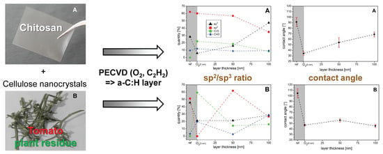
Effect of Cellulose Nanocrystals on the Coating of Chitosan Nanocomposite Film Using Plasma-Mediated Deposition of Amorphous Hydrogenated Carbon (a–C:H) Layers

1
Department of Physics, University Koblenz-Landau, 56070 Koblenz, Germany
2
Materials Science, Energy and Nanoengineering Department (MSN), Mohammed VI Polytechnic University (UM6P), 43150 Ben Guerir, Morocco
*
Author to whom correspondence should be addressed.
Submission received: 23 June 2020 / Revised: 28 July 2020 / Accepted: 28 July 2020 / Published: 30 July 2020
(This article belongs to the Special Issue Characterization of Disorder in Carbons)

Abstract

:
The substitution of petroleum-based polymers with naturally derived biopolymers may be a good alternative for the conservation of natural fossil resources and the alleviation of pollution and waste disposal problems. However, in order to be used in a wide range of applications, some biopolymers’ properties should be enhanced. In this study, biocompatible, non-toxic, and biodegradable chitosan (CS) film and CS reinforced with 10 wt% of cellulose nanocrystals (CN–CS) were coated with amorphous hydrogenated carbon layers (a–C:H) of different thickness. To investigate the effect of the nano-reinforcement on the a–C:H layer applied, mild radio frequency plasma enhanced chemical vapor deposition (RF-PECVD) was used to coat the CS and its CN–CS bio-nanocomposite film. Both the surface characteristics and the chemical composition were analyzed. The surface morphology and wettability were examined by ex-situ atomic force microscopy (AFM) and contact angle measurements (CA), respectively. Hereby, the relationship between sp2/sp3 ratios on a macroscopic scale was also evaluated. For the investigation of the chemical composition, the surface sensitive synchrotron X-ray radiation techniques near edge X-ray absorption fine structure (NEXAFS) and X-ray photoelectron spectroscopy (XPS) as well as diffuse reflectance infrared Fourier transform spectroscopy (DRIFT) were used.

Graphical Abstract

1. Introduction

Biopolymers are considered potential substitutes for conventional plastic materials because of their main advantages, including non-toxicity, biodegradability, wide availability, and biocompatibility; however, some of their properties must be improved to position them as materials that can compete with petroleum-based materials [1,2]. One of these biopolymers is chitosan (CS). CS is a natural cationic linear biopolymer and deacetylated derivative of chitin composed of β-(1,4)-2-acetamido-2-deoxy-D-glucose and β-(1,4)-2-amino-2-deoxy-D-glucose units [3]. It is one of the most important natural polymers because of its non-toxicity, antimicrobial activity, and excellent film-forming properties; without forgetting the disadvantages, it has a wide range of applications such as food, agriculture, biomedicine, pharmacy, packaging industries, materials science and wastewater treatment [1]. Nevertheless, in order to expand the fields of application of CS, the unfortunate mechanical and surface properties of CS must be enhanced by combining efficient nano-reinforcement and surface treatment technologies [2,3].
The incorporation of nano-reinforcing agents into biopolymers must be motivated by the excellent physico-chemical nano fillers properties and their nanoscale dispersion within the biopolymer matrix [4]. In this context, different biopolymers were used as polymer matrix to build bio-nanocomposite materials with high mechanical, optical, thermal, and barrier properties using cellulose nanocrystals (CN) as nano-reinforcing fillers [1,3,4]. Moreover, the surface properties such as hardness and abrasion resistance could be improved by the deposition of protective coatings, such as amorphous hydrogenated carbon (a–C:H) layers [5,6].
To modify the surface properties of polymers, a layer of hydrogen containing amorphous carbon (a–C:H) is often deposited on top. The carbon present in the layer is here both sp2 (π and σ) and sp3 bonded, whereby the sp2 clusters are limited to short chains embedded in a matrix of sp3 hydrogenated carbon and hydrogen. The physical surface properties modified by these layers can be controlled by varying the plasma parameters, the carbon source used, and the amount of hydrogen atoms in the plasma that crosslink the subsurface of the layer [7,8,9,10]. The properties of the layers are directly determined by the ratio of sp2 to sp3 hybridized carbons. If the ratio of sp3 bonds is high, the layer will have diamond-like properties—high hardness, chemical inertness, or high electrical resistance [10]. If the carbon in the layer is predominantly sp2 bound, a graphite-like layer is obtained—less robust with improved electrical conductivity [10]. This different chemical composition also influences the wettability or contact angle behavior of the deposited carbon layer. As already reported for several (bio)polymers, the ratio of sp2 to sp3 furthermore depends on the thickness of the deposited carbon layer [2,5,6,11,12,13,14]. These a–C:H layers are often produced by chemical vapor deposition (CVD), which can be further enhanced by the use of radio frequency induced plasma (RF-PECVD) [7,10,12,15]. This relatively gentle plasma technique works at low temperatures and is suitable for coating non-conductive substrates, making it ideal for polymers [10,14].
In this study, both CS and its CN-filled CS films were coated with a–C:H layers of 50 and 100 nm thickness. The coating was performed by RF-PECVD and acetylene plasma. It will be analyzed how the nano-reinforcement affects the coatings on the polymer and whether there are differences in the chemical composition of the respective layers. Ex-situ atomic force microscopy (AFM) was used to investigate the surface morphology of the deposited carbon layers. In addition, contact angle measurements (CA) were performed to compare the wettability of the surfaces and to evaluate the relationship between the sp2/sp3 ratios at the macroscopic level.
The chemical composition of the deposited a–C:H layers was analyzed using surface-sensitive synchrotron X-ray radiation techniques such as near-edge X-ray absorption fine structure (NEXAFS) and X-ray photoelectron spectroscopy (XPS). In addition, the diffusion reflectance infrared Fourier transform (DRIFT) technique was used to further analyze the chemical composition of the surface.

2. Materials and Methods

2.1. Samples Preparation

Sulfated cellulose nanocrystals (CN) were extracted from post-harvest tomato plant residue as described in our previous work [16]. Briefly, ground tomato plant residue was successively alkali-treated with 4 wt% NaOH solution, and then bleached using a solution made up of acetate buffer (27 g NaOH and 75 mL glacial acetic acid, diluted to 1 L of distilled water) and aqueous sodium chlorite (1.7 wt% NaClO2 in water). The obtained bleached cellulose microfibers were then subjected to sulfuric acid hydrolysis (64 wt%) at 50 °C under mechanical stirring for 10 min. This process resulted in CN stable aqueous suspension with an average diameter and length of 10.2 ± 3.2 nm and 410 ± 120 nm, respectively, and a crystallinity index of 81%.
The solvent-casting method was used for the preparation of neat chitosan (CS) and CN reinforced CS bio-nanocomposite films. Thus, CS (medium molecular weight—Sigma-Aldrich, Saint Louis, MO, USA) was dissolved in 1% (v/v) aqueous acetic acid solution at ambient temperature with constant stirring for 1 h; meanwhile, an aqueous suspension containing the desired amount 10 wt% of CN was prepared and ultrasonicated for 5 min and added to CS solution, resulting in 10 wt% CN filled CS mixture. The obtained mixture was mixed for 30 min at room temperature resulting in a homogeneous solution, then poured onto Petri dishes and air-dried in a laboratory hood at room temperature for 72 h to evaporate the water. Neat CS film was also prepared according to the same process but without the addition of CN. The bio-nanocomposite films were coded as CS and CN–CS for neat CS and CN reinforced CS film, respectively.
The chemical structure of CS and CN–CS was evaluated using Fourier transform infrared spectroscopy (FTIR, Perkin-Elmer Spectrum 2000, PerkinElmer, Inc., Waltham, MA, USA) equipped with ATR accessory. The FTIR spectra were recorded in the 4000–600 cm−1 range with a resolution of 4 cm−1 and an accumulation of 16 scans.

2.2. Coating Process

CS and CN–CS films were attached to a vacuum-suitable aluminum holder and subsequently placed as a whole in a high-vacuum chamber equipped with a radio-frequency plasma source (13.65 MHz) for the coating process (Copra DN 400, CCR GmbH, Troisdorf, Germany) [14]. The samples were maintained at a constant distance of 275 mm from the plasma source during all plasma processes [17]. The deposited a–C:H is an r-type layer as the samples were placed directly in front of the plasma source [12,13,18]. This layer has a higher degree of sp3 crosslinked carbon centers, which originated from a higher number of subplantation processes occurred during the plasma process [17]. During the treatment, no external BIAS was applied; instead, an averaged SELF-BIAS of −20 V developed on the samples. The entire process is described in detail elsewhere [14,19,20].
The plasma treatment was performed in two steps: First, the CS and CN–CS samples were pre-treated by an O2 plasma (RT, pressure 1 Pa, flux 65 sccm/min, power 200 W, active plasma duration 10 min) to clean and activate the sample surfaces [2,5,11,12,13,17,18]. Additionally, the adhesion of the layer deposited will be strengthened [21,22,23,24]. In the second step, samples were treated with a C2H2 plasma (RT, pressure 0.65 Pa, flux 65 sccm/min, power 107 W), with which the intended a–C:H layers were deposited [12,13,17,18]. The deposition rate is about 10 nm/min and is approximately constant over time, although there is less variation during initial growth [17]. Two different a–C:H layer thicknesses were realized on the films: 50 nm (5 min) and 100 nm (10 min). The layer thicknesses were chosen to examine at 50 nm the possible formation of an interlayer and the influence of the CN on it and at 100 nm to check whether the influence of the CN can be suppressed with a relatively thin a–C:H layer. During the complete plasma treatment, the substrate temperature never exceeded 40 °C to prevent melting of the material [18]. In addition to the polymer samples, silicon wafers (Silicon Materials, Kaufering, Germany), which were each half covered with aluminum foil, were attached to the sample holders. This allowed the determination of the thickness of the applied layer with a profilometer (Dektak 3, Veeco Instruments Inc., Plainview, NY, USA).

2.3. Surface Structure

The condition of the surface was examined with regard to two different aspects: Its topography and wettability. The investigation of the sample surface topography was performed by atomic force microscopy (AFM, Omicron Nano Technology GmbH, Taunusstein, Germany). Standard silicon nitride PNP-TR cantilevers (NanoAndMore GmbH, Wetzlar, Germany) were operated in contact mode at RT and ambient air conditions. To avoid tip blend and sample convolution, the tips were regularly checked with a cellulose acetate replica (Pelco, calibration sample for atomic force microscopy, 607-AFM, Plano GmbH, Wetzlar, Germany) of a 2160 lines/mm waffle pattern diffraction grating. To ensure accurate measures without image errors, all measurements (5 µm × 5 µm area) were performed at least at three different positions. All images have been analyzed using the commercial scanning probe image processor software (SPIP version 4.6.1, Image Metrology A/S, Hørsholm, Denmark). First, the images were plan corrected by a grade 3 LMS adjustment. A median filter was used to reduce the most severe horizontal noise. Furthermore, to reduce the low-frequency noise, a convolution smooth mean filter and a convolution smooth low pass filter were used. Finally, the long waves were removed and values outside the color boundaries were filtered out. All parameters of the filters were selected to achieve the best image quality and the most accurate representation of the surface for analysis [17].
Contact angle measurements were performed to check the wettability of the sample surfaces. At room temperature and in ambient air, the sessile drop technique (dosing needle, 1 µL, CHEMSOLUTE® HPLC water, Th. Geyer GmbH & Co. KG, Renningen, Germany) was applied to a contact angle goniometer (OCA15EC, Dataphysics Instruments GmbH, Filderstadt, Germany). After drop deposition, the contact angles left and right were recorded. The measurements were repeated at least at five different locations on each sample surface to check the homogeneity and to determine the mean value.

2.4. Chemical Composition

The binding states of the carbon atoms present on the surface were determined by X-ray photoelectron spectroscopy (XPS) and near edge X-ray absorption fine structure (NEXAFS). These XPS and NEXAFS measurements were performed at the HE-SGM beamline at Helmholtz-Zentrum Berlin during the low-alpha phase. The used beamline and detector are described elsewhere [25]. To avoid charging effects on the samples, the system was operated with a flood gun. In addition, the chemical composition of the surface was obtained using diffuse reflectance infrared Fourier transform (DRIFT) spectroscopy.
For the XPS measurements, first an overview spectrum (700 eV–0 eV) was recorded and then a detailed spectrum for the analysis of the different bonding states of the carbon atoms. Here, the C1s peak was examined at least at two different locations on the sample surface. Repeated measurements were performed to check reproducibility and to evaluate the homogeneity and stability of the a–C:H layers. The commercially available software CasaXPS (software version 2.3.18, Casa Software Ltd., Teignmouth, UK) was used to analyze the C1s spectra. The percentages of sp2, sp3, C–O, and C=O bonds in the total C1s peak were identified and evaluated. The results obtained were plotted against the corresponding layer thicknesses using Origin 8.1 software.
For the NEXAFS measurements, both the C–K and O–K edges of the samples were recorded. The C–K edge was also recorded in at least two locations to show the homogeneity of the measurements. The O-K edges were only used to demonstrate the presence or absence of oxygen on the sample surface and will not be discussed further. All NEXAFS measurements were performed in the “magic angle” at a photon incidence angle of 55° with the partial electron yield (PEY). With PEY, a counter-voltage is applied and not all electrons escaping from the material can reach the measuring electronics. Therefore, the measurement is even more surface sensitive [25]. The spectra obtained from the C–K edges were analyzed using the commercial software Origin. For this purpose, the spectra were first normalized and then adapted to the decreasing ring current present at the BESSY experimental station during the low-alpha phase (100 mA decay mode). A correction for possible contamination of the grid by a previously measured gold edge was then performed. The individual steps are described in detail and summarized by Watts et al. [26]. Further analysis was performed using a self-written peak evaluation program and Origin 8.1 software.
For the DRIFT measurements, a Shimadzu-Fourier transform spectrometer (IRPrestige-21, Kyoto, Japan) equipped with the diffuse reflectance unit DRS-8000 was used. The measurements were performed in ambient air and at room temperature [27,28]. Two different spectra were recorded for analysis. A full spectrum between 500 and 4000 cm−1 was recorded to investigate thickness dependent influences on the chemical surface structure. For this purpose, a resolution of 4 wave numbers at 100 repetitions was chosen. Subsequently, a detailed measurement was performed for the spectral range of 2800–3100 cm−1, the C–H stretching region [29,30]. Here, a resolution of 1 wave number and 300 repetitions was used. As reference for the raw polymer measurements and the measurements of the 50 and 100 nm a–C:H layers on the CS and CN–CS samples, respectively, the respective O2 plasma treated sample was used. All measurements were repeated at least at three positions on the sample surface to ensure sample homogeneity. The analysis of the obtained spectra was then performed with the commercial IR-Solution—FTIR Control Software (software version 1.30, Shimadzu Corporation, Kyoto, Japan). First, a multipoint baseline was inserted using the integrated manipulation tool, followed by a software-integrated smoothing manipulation (this changes only the appearance of the graph, but not the information).

3. Results and Discussion

3.1. Processing of Films

The mixture of CS and 10 wt% CN is simple to achieve under controlled conditions, allowing a homogeneous and stable aqueous mixture to be formed. Films with high quality, flexibility, and smooth surface were developed by casting these solutions on Petri dishes and evaporating of the solvent water in this case.
CS biopolymer is characterized by its large number of functional groups, including hydroxyl and amino groups that could be useful in creating strong interfacial interactions with CN [1]. On the other hand, the sulfuric acid hydrolyzed CN exhibit free hydroxyl and inserted anionic sulfate groups on their surfaces, which make them highly water dispersible nanomaterials [3,31]. Accordingly, the compatibility between CN and CS will result in a good dispersion of CN within CS, thus improving the properties of the generated bio-nanocomposite films [31]. By adding CN into CS, an interconnected bond network can be formed via strong electrostatic interactions and hydrogen bonding, as indicated in Figure 1, and confirmed by FTIR analysis (Figure 2).

3.2. FTIR Characterization of the Samples

The FTIR measurements were performed to investigate the structure of CS and CN–CS bio-nanocomposite films. Figure 2 presents the FTIR spectra of CS and CN–CS samples; for CS spectrum, the band at 3244 cm−1 originated from O–H and N–H hydrogen band stretches. The bands at 2926 and 2871 cm−1 are attributed to C–H stretching. The band at 1635 cm−1 is due to C–O stretching of the acetyl group. The band at 1545 cm−1 is associated with N–H bending and stretching. The bands at 1406 cm−1 are associated with asymmetrical C–H bending of CH2 group [1,31]. For the CN–CS bio-nanocomposite films, the peak observed at 3244 cm−1 assigned to –OH stretching, shifted to 3308 cm−1 (Figure 2). Aside from these peaks, the small band observed at 1201 cm−1 in CN–CS spectrum assigned to SO2−3 confirms the strong interactions occurring between CS and NC sulfate groups [1,31]. FTIR results confirmed the strong electrostatic interactions and hydrogen bonding occurring between the free functional groups of NC and CS biopolymer.

3.3. Topography and Wettability

Figure 3 shows the AFM measurements of CS and CN–CS samples. Shown are the respective raw samples, the oxygen-treated samples, and the ones coated with 50 and 100 nm a–C:H. The associated roughness measurements are provided in the Supplementary Materials: Table S1 for CS and Table S2 for CN–CS. The raw chitosan sample has some smaller particle-like structures on the surface, which are arranged in a line-like pattern. Also, a deeper furrow is recognizable on the raw polymer. After O2 plasma treatment the surface appears roughened and more particle-like structures become visible, which is caused by the impact of the oxygen ions. The 50 nm a–C:H layer on chitosan shows a uniform, homogeneous structure consisting of small grains. Moreover, some larger grains are visible on this closed layer of grains, which is an indication that another layer is growing on the closed layer below. The presence of a uniform grain structure is indicative for an already completed interlayer phase. The interlayer, a mixed phase of base material and applied a–C:H layer, must therefore be less than 50 nm thick. With the application of the 100 nm a–C:H layer, the trend of the 50 nm sample continues.
The CN–CS sample is rougher and has significantly more particle structures compared to the non-reinforced polymer. Interestingly, the surface of the polymer appears less rough and even smoother after O2 plasma treatment. Also, in this case, the application of a 50 nm a–C:H-layer results in a closed layer coverage with homogeneous structures. Consequently, the interlayer phase is also completed here with the application of a 50 nm layer. The sample covered with 100 nm is similar to the 50 nm sample, even if the grain structure looks less fine-grained. It should be noted that the CN–CS looks more wavy or less plane in contrast to the non-reinforced chitosan. A comparison of the AFM images for both materials shows a different raw material surface. Additionally, the a–C:H layer surface for the 50 nm thick layers display slight differences indicating a different initial growth. For both substrate materials, bigger grains are visible at a film thickness of 50 nm. This is an indication for a completed interlayer between the basic material and the a–C:H layer. A similar behavior has already been observed on other polymers [12,13,17]. The fiber reinforcement therefore does not suppress interlayer formation. However, no statement can be made here at this point about how pronounced the interlayer is.
Figure 4 displays the results of the contact angle measurements for the respective raw samples, the O2 plasma treatments, and the samples coated with 50 and 100 nm a–C:H.
The wettability of surfaces with fluids is decisively influenced by three different factors: Firstly, different surface topographies, as the roughness influences the wettability of the surface [32,33,34]. The second factor is the interaction of chemical bonds on the surface [35,36,37,38]. A surface enriched with oxygen becomes more reactive with water through the formation of oxygen-containing functional groups [38]. However, if the surface is hydrogenated, the free dangling bonds on the surface become saturated with hydrogen and strong C–H bonds are formed. This increases the hydrophobic character of the surface and leads to a weaker interaction between film and water [35,36,37]. Finally, the different hybridization states of the carbon atoms on the surface influence the wettability [39,40,41]. A surface rich in sp2-hybridized carbon has a higher contact angle than a surface rich in sp3. This is due to the different surface free energies [39,40,41]. The polarity of the dangling bonds of an sp3-rich surface is relatively weak compared to that of a sp2-hybridized surface [9,39].
Figure 4A shows the contact angles for the CS samples. The untreated CS shows a contact angle of 91°. With the O2 plasma treatment, it drops to a value of 35° due to the oxidation of the surface. With the application of a 50 nm a–C:H layer, the contact angle increases to 54°. This increase can be attributed to the fact that the surface is no longer oxidized and to the hybridization of the carbon atoms. When the 100 nm a–C:H layer thickness is reached, the contact angle increases further to 69°.
Figure 4B shows the results of the contact angle measurements for CN–CS. The contact angle of the untreated sample is 105°. Therefore, the reinforcement of the polymer leads to an increase of the contact angle compared to the normal CS. After the CN–CS sample is treated with the O2 plasma, the contact angle decreases strongly to 47°. As with the CS sample, this is also due to the oxidation of the surface. When a 50 nm a–C:H layer is applied, the measured contact angle increases to 56°, which is comparable to the 50 nm a–C:H layer on the CS sample. If a 100 nm a–C:H layer is deposited, the contact angle decreases to 46°. This is a clear difference to the 100 nm a–C:H layer on the CS sample. While the contact angle increases there, it decreases on the CN–CS. A possible explanation is different hybridization states of the carbon atoms in the respective 100 nm layer, even if both layers were coated simultaneously in the same plasma process. Therefore, a clear substrate effect is recognizable.

3.4. Chemical Composition

The chemical composition of the sample surfaces was examined for further analysis. The X-ray spectroscopic methods XPS and NEXAFS, both synchrotron based, as well as the infrared-based technique DRIFT were used for this work. First, the results of the XPS studies are presented, which are shown in Figure 5. The measurements were performed and analyzed as described in the experimental setup. The peak positions have been confirmed by NIST database and the work of other groups [42,43,44]. More details for the XPS spectra can be found in the Supplementary Materials (Figures S1–S4).
The results for the CS are shown in Figure 5A. The carbon atoms on the surface of the raw CS are 62% sp2 bonded, the proportion of sp3 bonds is 28%. If the sample is treated with O2 plasma, the proportion of sp2 bonds hardly decreases noticeably to 61%, the sp3 bonds drop to 6% due to oxygen treatment. While the C=O bonds remain almost constant, the C–O bonds increase strongly to 22% and thus a clear oxidation of the surface is recognizable. If a 50 nm a–C:H layer is deposited, the C–O and C=O bonds decrease. Also, the sp2 content decreases slightly to 57% in favor of a sp3 hybridized surface, which reaches a content of 16%. The previously oxygen plasma treated polymer is now covered with the a–C:H layer. If the layer thickness increases to 100 nm, the sp2 bonds decrease further and reach a proportion of 35%. The sp3 bonds increase to 48% and become the dominant bond present on the surface.
Figure 5B shows the XPS results for the CN–CS. Like before the CS, the untreated polymer substrate is mostly sp2 bound, but the percentage here is only 51%, while the sp3 hybridization of the carbon atoms is much more pronounced with 46% than for the CS. Oxygen bonds are more or less not present, which indicates that the embedded cellulose nanocrystals alter the chemical structure of the polymer surface to be coated. The absence of oxygen bonds changes during the O2 plasma treatment. The proportion of the C–O bond increases strongly and reaches a value of 60%, that of the C=O bond to 20%. The sp2 bonds have practically disappeared and the amount of sp3 bonds is only 20%. Compared to the CS sample, the oxidation of the surface is much more pronounced due to the fiber reinforcement. After the application of a 50 nm thick a–C:H layer, the hybridization of the carbon atoms changes strongly again. Sixty-two percent of the atoms are now sp2 bonded, and the proportion of sp3 bonds remains almost unchanged at 21%. Even though the values approach those of the 50 nm a–C:H coating on the CS, both proportions are 5 % higher. Presumably, at this layer thickness, the fibers do not yet have a great influence on the applied a–C:H layer. As the coating thickness increases to 100 nm, the proportion of sp2 bonds decreases sharply to 27%, while the proportion of sp3 bonds increases to nearly 29%. Surprisingly, the overall amount of carbon–oxygen bonds on the coated surface also increases. The decrease of sp2 and increase of sp3 bonds is also observable for the 100 nm a–C:H layer on the CS. For the fiber-reinforced CS, however, it appears to be less pronounced, but follows a reversal point of both with a previous complete absence of sp2 bonds, which is probably due to the strongly increased amount of oxygen bonds. In both the normal and fiber-reinforced CS, the 100 nm a–C:H layer has a higher proportion of sp3 than sp2 bonds. It is not entirely clear where the large proportion of oxygen bonds in the 100 nm CN–CS comes from. Presumably, this is a saturation effect of free receptive surface bonds by ambient air-oxygen when the chamber is vented, since the samples must be transferred from the chamber for further analysis.
The XPS measurements show a significant difference in the hybridization states of the carbon atoms between the raw CS and the CN–CS. Also, for O2 plasma treatment, it is noticeable that the oxidation is stronger in the CN–CS sample. The 50 nm a–C:H layer has a chemically similar surface for both materials: A layer dominated by sp2 bonded carbon (62 resp. 57%) with a similar content of sp3 bonded carbon (21 resp. 16%). Apparently, even with relatively thin layers, there is only a small influence of the fiber reinforcement on the deposited a–C:H layer, except the history of oxygen treatment. With continued coating, both materials behave similarly. In favor of a weaker proportion of sp2 bond, the sp3 amount increases, even if the CN–CS sample shows a higher oxidation behavior.
The results of the NEXAS measurements shown in Figure 6A displays the NEXAFS results for untreated CS and Figure 6B for the CN–CS. The peak positions have been determined to C=C π (284.85 eV), C–H (286.15 eV), C–C (288.35 eV) and C=C σ (292.55 eV) [45,46,47,48,49]. In the raw polymer sample for the untreated CS (6A, black line), the peaks of the C=C π and σ, which represent the sp2 carbon bonds, and the C–C peak belonging to the sp3 are clearly visible. With the O2 plasma treatment (red line) the C–C peak is less evident. The two peaks belonging to the sp2 bond also weaken slightly compared to their surroundings, which is consistent with the XPS measurements. If a 50 nm a–C:H layer (green line) is applied, clear peaks of the sp2 bond can be seen; for the sp3 peak (C–C bond), only one shoulder is visible. This corresponds to the XPS measurements, even if the ratios do not match. If the layer thickness increases to 100 nm (blue line), no further changes to the 50 nm layer are noticeable, which is not consistent with the XPS measurements. However, this may be due to the different penetration depths of the different techniques.
For the CN–CS samples shown in Figure 6B, the raw polymer (black line) shows that the C–C bond is stronger compared to the normal CS. The two C=C (π and σ) are clearly visible. The relatively strong C–C bond was already observable in XPS. With the O2 plasma treatment (red line), the intensity of the peaks belonging to the sp2 hybridization increases slightly, while the C–C peak is strongly narrowed and therefore less pronounced. This decrease in sp3 binding was also already present in XPS. With deposition of a 50 nm a–C:H layer (green line), the sp2 bonds (C=C peaks) are much more pronounced and the C–C peak is only very weakly accentuated. The results of the 100 nm a–C:H layer again do not change compared to the 50 nm sample, even if the intensity is somewhat lower over the entire spectrum.
In addition to the X-ray spectroscopy, DRIFT investigations were performed and analyzed to fully evaluate the chemical environment on the layer surface. For the investigations of the a–C:H coatings, the measurements of the O2 plasma-treated polymer samples (CS/CN–CS) were used as reference spectrum. This is necessary because all samples were pre-treated with oxygen plasma before the carbon deposition and only in this way can the pure layer bonds be investigated. DRIFT spectra are evaluated on the basics of infrared spectroscopy [29] and according to previous results of other groups and own observations [13,18,30,50,51].
First, the full spectrum of 450−4500 cm−1 was recorded. With these spectra it was possible to investigate in which wavenumber regions there are differences between the examined layer surfaces. For this measurement, 100 repetitions with a resolution of four wave numbers were used. Subsequently, detailed measurements of the region 2800−3050 cm−1 were performed. This is the C–H stretching region where the carbon bonds (=CH2 and –CH3) are located [29,30,50,51]. Here, a resolution of one wave number at 300 repetitions was used.
The obtained spectra of the DRIFT measurements are shown in Figure 7: Figure 7A shows the results for the coated CS and Figure 7B for the CN–CS. Remarkable for both series is that no sp2 oscillations are visible and only the bonds belonging to sp3 are formed. This problem has already occurred with other polymers coated with a–C:H [6].
Figure 7A shows the DRIFT measurements for the a–C:H coated CS samples. Two oscillations are clearly visible: The sp3 CH2 (as = asymmetric) oscillation at 2920 cm−1 [50,51] and the corresponding sp3 CH2 (s = symmetric) oscillation at 2851 cm−1 [50,51]. For the 50 nm a–C:H layer thickness, the sp3 CH2 (as) peak also appears to overlap with the sp3 CH oscillation at 2902 cm−1 [51]. If the thickness is increased to 100 nm, there is a small shift to 2922 and 2852 cm−1, respectively, for both oscillations. This shift to a higher wavenumber indicates that the carbon–hydrogen bonding energy has increased. Therefore, the carbon–hydrogen bond distance for the =CH2 group has decreased [29]. This change in the bond spacing has already been demonstrated for such a–C:H coatings on several (bio)polymers [2,5,6,11,13,18]. The overlapping sp3 CH bond also disappears at 100 nm thickness.
Figure 7B shows the results for the CN–CS measurements. For the 50 nm layer, only two of the three peaks that were visible for the coated CS are present, the sp3 CH2 (s) peak is not present here. Additionally, the sp3 CH2 (as) and the sp3 CH vibration peak are not superimposed but separated. In addition, the system differs chemically from the coated CS sample in that the sp3 CH2 (as) here is located at 2940 cm−1 and the carbon–hydrogen distance is thus smaller. With a layer thickness of 100 nm a–C:H the sp3 CH oscillation also disappears here. However, the sp3 CH2 (s) peak at 2850 cm−1 becomes visible. In addition, the sp3 CH2 (as) oscillation performs a large shift-back to 2918 cm−1, which in turn indicates the typical pattern towards the a–C:H layer.
The presence of =CH2 oscillations in the 50 nm a–C:H layers also shows that an interlayer between both materials and the a–C:H layer is completed [13]. According to the present DRIFT spectra and compared to previous results [13], it can also be concluded that less than 50 nm layer thickness is required to complete the interlayer phase. However, it must be mentioned that the chemical systems for the present 50 nm samples are different. Both depositions are comparable only after reaching a layer thickness of 100 nm, which means that the growth of the a–C:H layer will gradually level out and become more and more the same after completion of the intermediate layer.

4. Conclusions

Both pure CS film and CN–CS nanocomposite film were coated with stable a–C:H layers of 50 and 100 nm thickness. The objective was the comparison of whether the reinforcement of such biopolymer influences the growth behavior of these a–C:H layers. The coating was performed by the use of an RF-PECVD plasma with acetylene as precursor gas. AFM and contact angle measurements were performed to check surface properties. The chemical surface composition was investigated with the synchrotron X-ray methods XPS and NEXAFS as well as with the infrared based technique DRIFT.
AFM measurements show similar results for both substrates. In both cases, a homogeneous grain pattern occurs at 50 nm film thickness, which indicates the completion of the interlayer phase. However, for the 100 nm layer thickness, the grain structure of the pure CS seems to be slightly finer, whereas the CN–CS material itself is wavier than the pure CS. The completion of the interlayer phase is also confirmed by DRIFT measurements, since =CH2 bonds are already present at 50 nm, which are only formed after completion of this interlayer. The contact angles show that the reinforcement of the raw CS leads to an increase of the contact angle from 91° to 105°. Both are oxidized by the oxygen plasma treatment and the contact angle is reduced. At 50 nm film thickness, the contact angles of 54° and 56° are almost identical. However, at 100 nm they differ again by 23° (69° CS; 46° CN–CS), which indicates a possible substrate effect.
The XPS results show large differences in the hybridization of the carbon binding in both materials. The CS is much stronger sp2 bonded, while the CN–CS has a nearly balanced hybridization. After O2 treatment, it is noticeable that the CN–CS is oxidized much stronger than the pure CS. For the 50 nm a–C:H layer, both polymeric carbon hybridization states are almost equal, which confirms the results of the contact angle measurements. With 100 nm, the carbon in both samples is bound a little stronger sp3 than sp2, whereas the CN–CS shows more oxidation. The NEXAFS measurements are very similar for both substrates at 50 and 100 nm. Only for CN–CS the intensity of the 100 nm a–C:H spectrum is a little higher than for the 50 nm. The DRIFT results show a film thickness dependent change of the chemical structure with increasing film thickness. With an increase from 50 nm to 100 nm, the sp3 CH oscillation is no longer visible. Shifts in the peak positions indicate changing distances between the carbon and hydrogen atoms in both ways.
Overall, this investigation reveals that the reinforcement of CS with CN–CS fibers does not cause a significant variation for the resulting coatings. Both of the applied a–C:H layers are stable, and the interlayer phase is already completed with 50 nm.
However, further investigations are necessary for a more detailed analysis of the growth of the layer on the polymer. Thinner layers would provide information about the different initial growth of the layer while thicker layers would show if and how the modification of the base material affects the applied a–C:H layer and their stability.

Supplementary Materials

The following are available online at https://www.mdpi.com/2311-5629/6/3/51/s1, Table S1. AFM roughness data for the chitosan (CS) samples, Table S2. AFM roughness data for the nanocrystal reinforced chitosan (CS–CN) samples, Figure S1a. XPS survey spectra (ref + O2 plasma treated) for the chitosan (CS) samples in the range from 0–700 eV, Figure S1b. XPS survey spectra (50 nm + 100 nm a–C:H) for the chitosan (CS) samples in the range from 0–700 eV, Figure S2a. XPS survey spectra (ref + O2 plasma treated) for the reinforced chitosan (CS–CN) samples in the range from 0–700 eV, Figure S2b. XPS survey spectra (50 nm + 100 nm a–C:H) for the reinforced chitosan (CS–CN) samples in the range from 0–700 eV, Figure S3a. C1s peaks (ref + O2 plasma treated) for the chitosan (CS) samples, Figure S3b. C1s peaks (50 nm + 100 nm a–C:H) for the chitosan (CS) samples, Figure S4a. C1s peaks (ref + O2 plasma treated) for the reinforced chitosan (CS–CN) samples, Figure S4b. C1s peaks (50 nm + 100 nm a–C:H) for the reinforced chitosan (CS–CN) samples.

Author Contributions

T.S., Z.K., M.E.A., and C.B.F. conceptualized the study and developed the related methodology. Z.K. processed the polymer films and T.S. made the preparations for the a–C:H coatings. T.S. performed the data evaluation, visualization, and wrote the original draft. T.S., Z.K., M.E.A., S.W., and C.B.F. reviewed and edited the manuscript. FTIR acquisition and evaluation was conducted by Z.K. AFM, CA, NEXAFS, XPS, and DRIFT acquisition and evaluation of the a–C:H coatings was conducted by T.S., M.E.A., S.W., and C.B.F. contributed in terms of funding acquisition, project management, supervision, and overall guidance in the study. All authors have read and agreed to the published version of the manuscript.

Funding

Funding for this work was provided by the German Research Foundation DFG (Deutsche Forschungsgemeinschaft) through the project WE 4100/23-1 and FI 1802/14-1. The financial assistance of the Office Chérifien des Phosphates (OCP S.A.) in the Moroccan Kingdom toward this research is hereby acknowledged. T.S. and C.B.F. thankfully acknowledge the financial support by HZB. Additionally, the authors gratefully acknowledge the financial support provided by DAAD funds within the framework of German-Arab Transformation Partnership 2018 and 2019, Program line 2, DAAD Project ID: 57448234 and 57514023.

Acknowledgments

The authors thank Heinz Busch (NTTF Coatings GmbH, Rheinbreitbach, Germany) for the possibility of industrial coating of the samples and Joachim Scholz (University of Koblenz-Landau, department of chemistry) for the DRIFT equipment. The authors also want to thank Alexei Nefedov from KIT (Karlsruhe Institute for Technology, Group: Chemistry of oxidic and organic interfaces; X-ray and Electron Spectroscopy at Interfaces) for beamtime support. We thank HZB for the allocation of synchrotron radiation beamtime.

Conflicts of Interest

The authors declare no conflict of interest.

References

  1. Yadav, M.; Behera, K.; Chang, Y.-H.; Chiu, F.-C. Cellulose Nanocrystal Reinforced Chitosan Based UV Barrier Composite Films for Sustainable Packaging. Polymers (Basel) 2020, 12, 202. [Google Scholar] [CrossRef] [PubMed] [Green Version]
  2. Schlebrowski, T.; Beucher, L.; Bazzi, H.; Hahn, B.; Wehner, S.; Fischer, C.B. Changing Contents of Carbon Hybridizations in Amorphous Hydrogenated Carbon Layers (a–C:H) on Sustainable Polyhydroxybutyrate (PHB) Exhibit a Significant Deterioration in Stability, Depending on Thickness. C J. Carbon Res. 2019, 5, 52. [Google Scholar] [CrossRef] [Green Version]
  3. El Achaby, M.; Kassab, Z.; Barakat, A.; Aboulkas, A. Alfa fibers as viable sustainable source for cellulose nanocrystals extraction: Application for improving the tensile properties of biopolymer nanocomposite films. Ind. Crop. Prod. 2018, 112, 499–510. [Google Scholar] [CrossRef]
  4. Kassab, Z.; Abdellaoui, Y.; Salim, M.H.; Bouhfid, R.; Qaiss, A.E.K.; El Achaby, M. Micro- and nano-celluloses derived from hemp stalks and their effect as polymer reinforcing materials. Carbohydr. Polym. 2020, 245, 116506. [Google Scholar] [CrossRef] [PubMed]
  5. Schlebrowski, T.; Acharchi, H.; Hahn, B.; Wehner, S.; Fischer, C.B. Refinement of Sustainable Polybutylene Adipate Terephthalate (PBAT) with Amorphous Hydrogenated Carbon Films (a-C:H) Revealing Film Instabilities Influenced by a Thickness-Dependent Change of sp2/sp3 Ratio. Materials 2020, 13, 1077. [Google Scholar] [CrossRef] [PubMed] [Green Version]
  6. Schlebrowski, T.; Rouabeh, W.; Wehner, S.; Fischer, C.B. Specifying the interlayer turning point and dehydrogenation in a-C:H layers plasma deposited on high-density polyethylene with X-ray synchrotron techniques. Thin Solid Films 2019, 691, 137617. [Google Scholar] [CrossRef]
  7. Grill, A. Plasma-deposited diamondlike carbon and related materials. IBM J. Res. Dev. 1999, 43, 147–162. [Google Scholar] [CrossRef]
  8. Mohagheghpour, E.; Rajabi, M.; Gholamipour, R.; Larijani, M.M.; Sheibani, S. Ion beam energy dependence of surface and structural properties of amorphous carbon films deposited by IBSD method on Ni–Cu alloy. J. Mater. Res. 2017, 32, 1258–1266. [Google Scholar] [CrossRef]
  9. Robertson, J. Diamond-like amorphous carbon. Mater. Sci. Eng. R. Rep. 2002, 37, 129–281. [Google Scholar] [CrossRef] [Green Version]
  10. Robertson, J. Plasma Deposition of Diamond-Like Carbon. Jpn. J. Appl. Phys. 2011, 50, 01AF01. [Google Scholar] [CrossRef]
  11. Schlebrowski, T.; Beucher, L.; Bazzi, H.; Hahn, B.; Wehner, S.; Fischer, C.B. Prediction of a-C:H layer failure on industrial relevant biopolymer polylactide acide (PLA) foils based on the sp2/sp3 ratio. Surf. Coat. Technol. 2019, 368, 79–87. [Google Scholar] [CrossRef]
  12. Catena, A.; Agnello, S.; Rösken, L.M.; Bergen, H.; Recktenwald, E.; Bernsmann, F.; Busch, H.; Cannas, M.; Gelardi, F.M.; Hahn, B.; et al. Characteristics of industrially manufactured amorphous hydrogenated carbon (a-C:H) depositions on high-density polyethylene. Carbon 2016, 96, 661–671. [Google Scholar] [CrossRef]
  13. Catena, A.; Guo, Q.; Kunze, M.R.; Agnello, S.; Gelardi, F.M.; Wehner, S.; Fischer, C.B. Morphological and Chemical Evolution of Gradually Deposited Diamond-Like Carbon Films on Polyethylene Terephthalate: From Subplantation Processes to Structural Reorganization by Intrinsic Stress Release Phenomena. ACS Appl. Mater. Interfaces 2016, 8, 10636–10646. [Google Scholar] [CrossRef] [PubMed] [Green Version]
  14. Rohrbeck, M.; Körsten, S.; Fischer, C.B.; Wehner, S.; Kessler, B. Diamond-like carbon coating of a pure bioplastic foil. Thin Solid Films 2013, 545, 558–563. [Google Scholar] [CrossRef]
  15. Fischer, C.B.; Rohrbeck, M.; Wehner, S.; Richter, M.; Schmeißer, D. Interlayer formation of diamond-like carbon coatings on industrial polyethylene: Thickness dependent surface characterization by SEM, AFM and NEXAFS. Appl. Surf. Sci. 2013, 271, 381–389. [Google Scholar] [CrossRef]
  16. Kassab, Z.; Kassem, I.; Hannache, H.; Bouhfid, R.; Qaiss, A.E.K.; El Achaby, M. Tomato plant residue as new renewable source for cellulose production: Extraction of cellulose nanocrystals with different surface functionalities. Cellulose 2020, 27, 4287–4303. [Google Scholar] [CrossRef]
  17. Catena, A.; McJunkin, T.; Agnello, S.; Gelardi, F.M.; Wehner, S.; Fischer, C.B. Surface morphology and grain analysis of successively industrially grown amorphous hydrogenated carbon films (a-C:H) on silicon. Appl. Surf. Sci. 2015, 347, 657–667. [Google Scholar] [CrossRef]
  18. Catena, A.; Kunze, M.R.; Agnello, S.; Gelardi, F.M.; Wehner, S.; Fischer, C.B. Amorphous hydrogenated carbon (a-C:H) depositions on polyoxymethylene: Substrate influence on the characteristics of the developing coatings. Surf. Coat. Technol. 2016, 307, 658–665. [Google Scholar] [CrossRef]
  19. Kleinen, L.; Böde, U.; Laube, N. Ex-vivo investigations on the friction behavior of amorphous carbon coated ureteral stents. Diam. Relat. Mater. 2008, 17, 1746–1750. [Google Scholar] [CrossRef]
  20. Kleinen, L.; Böde, U.; Schenk, K.; Busch, H.; Bradenahl, J.; Müller, S.C.; Hillebrands, B.; Laube, N. Amorphous Carbon Coatings Inhibit Crystalline Biofilm Formation on Urological Implants. Plasma Process. Polym. 2007, 4, S386–S391. [Google Scholar] [CrossRef]
  21. Aguiar, P.H.L.; Oliveira, É.C.; Cruz, S.A. Modification of clarified polypropylene by oxygen plasma to improve the adhesion of thin amorphous hydrogenated carbon films deposited by plasma enhanced chemical vapor deposition. Polym. Eng. Sci. 2013, 53, 1065–1072. [Google Scholar] [CrossRef]
  22. Mandolfino, C. Polypropylene surface modification by low pressure plasma to increase adhesive bonding: Effect of process parameters. Surf. Coat. Technol. 2019, 366, 331–337. [Google Scholar] [CrossRef]
  23. Ozeki, K.; Kobayashi, S.; Hirakuri, K.K.; Aoki, H.; Fukui, Y. Oxygen plasma pre-treatment improves the wear properties of a diamond-like carbon film coated on UHMWPE and PMMA for biomaterials. Biomed. Mater. Eng. 2007, 17, 175–182. [Google Scholar] [PubMed]
  24. Vishnuvarthanan, M.; Rajeswari, N. Effect of mechanical, barrier and adhesion properties on oxygen plasma surface modified PP. Innov. Food Sci. Emerg. Technol. 2015, 30, 119–126. [Google Scholar] [CrossRef]
  25. Nefedov, A.; Wöll, C. Advanced Applications of NEXAFS Spectroscopy for Functionalized Surfaces. In Surface Science Techniques; Bracco, G., Holst, B., Eds.; Springer Berlin Heidelberg: Berlin, Heidelberg, Germany, 2013; pp. 277–303. ISBN 978-3-642-34242-4. [Google Scholar]
  26. Watts, B.; Thomsen, L.; Dastoor, P.C. Methods in carbon K-edge NEXAFS: Experiment and analysis. J. Electron. Spectros. Relat. Phenomena. 2006, 151, 105–120. [Google Scholar] [CrossRef]
  27. D’Souza, L.; Devi, P.; Kamat, T.; Naik, C.G. Diffuse reflectance infrared fourier transform spectroscopic (DRIFTS) investigation of E. coli, Staphylococcus aureus and Candida albicans. Indian J. Mar. Sci. 2009, 38, 45–51. [Google Scholar]
  28. Armaroli, T.; Bécue, T.; Gautier, S. Diffuse Reflection Infrared Spectroscopy (Drifts): Application to the in Situ Analysis of Catalysts. Oil Gas Sci. Technol. 2004, 59, 215–237. [Google Scholar] [CrossRef]
  29. Günzler, H.; Gremlich, H.-U. IR spectroscopy. An Introduction; Wiley-VCH: Weinheim, Germany, 2002; ISBN 3-527-28896-1. [Google Scholar]
  30. Koidl, P.; Wild, C.; Dischler, B.; Wagner, J.; Ramsteiner, M. Plasma Deposition, Properties and Structure of Amorphous Hydrogenated Carbon Films. Mater. Sci. Forum 1991, 52–53, 41–70. [Google Scholar] [CrossRef]
  31. El Miri, N.; Abdelouahdi, K.; Zahouily, M.; Fihri, A.; Barakat, A.; Solhy, A.; El Achaby, M. Bio-nanocomposite films based on cellulose nanocrystals filled polyvinyl alcohol/chitosan polymer blend. J. Appl. Polym. Sci. 2015, 132, 1–13. [Google Scholar] [CrossRef]
  32. Banerjee, D.; Mukherjee, S.; Chattopadhyay, K.K. Controlling the surface topology and hence the hydrophobicity of amorphous carbon thin films. Carbon 2010, 48, 1025–1031. [Google Scholar] [CrossRef]
  33. Barthlott, W.; Neinhuis, C. Purity of the sacred lotus, or escape from contamination in biological surfaces. Planta 1997, 202, 1–8. [Google Scholar] [CrossRef]
  34. Feng, L.; Li, S.; Li, Y.; Li, H.; Zhang, L.; Zhai, J.; Song, Y.; Liu, B.; Jiang, L.; Zhu, D. Super-Hydrophobic Surfaces: From Natural to Artificial. Adv. Mater. 2002, 14, 1857–1860. [Google Scholar] [CrossRef]
  35. Ostrovskaya, L.; Perevertailo, V.; Ralchenko, V.; Dementjev, A.; Loginova, O. Wettability and surface energy of oxidized and hydrogen plasma-treated diamond films. Diam. Relat. Mater. 2002, 11, 845–850. [Google Scholar] [CrossRef]
  36. Ostrovskaya, L.Y. Studies of diamond and diamond-like film surfaces using XAES, AFM and wetting. Vacuum 2002, 68, 219–238. [Google Scholar] [CrossRef]
  37. Piazza, F.; Morell, G. Wettability of hydrogenated tetrahedral amorphous carbon. Diam. Relat. Mater. 2009, 18, 43–50. [Google Scholar] [CrossRef]
  38. Tay, B.K.; Sheeja, D.; Lau, S.P.; Guo, J.X. Study of surface energy of tetrahedral amorphous carbon films modified in various gas plasma. Diam. Relat. Mater. 2003, 12, 2072–2076. [Google Scholar] [CrossRef]
  39. Paul, R.; Das, S.N.; Dalui, S.; Gayen, R.N.; Roy, R.K.; Bhar, R.; Pal, A.K. Synthesis of DLC films with different sp2/sp3 ratios and their hydrophobic behaviour. J. Phys. D Appl. Phys. 2008, 41, 55309. [Google Scholar] [CrossRef]
  40. Werder, T.; Walther, J.H.; Jaffe, R.L.; Halicioglu, T.; Koumoutsakos, P. On the Water−Carbon Interaction for Use in Molecular Dynamics Simulations of Graphite and Carbon Nanotubes. J. Phys. Chem. B 2003, 107, 1345–1352. [Google Scholar] [CrossRef]
  41. Zhou, Y.; Wang, B.; Song, X.; Li, E.; Li, G.; Zhao, S.; Yan, H. Control over the wettability of amorphous carbon films in a large range from hydrophilicity to super-hydrophobicity. Appl. Surf. Sci. 2006, 253, 2690–2694. [Google Scholar] [CrossRef]
  42. Dietrich, P.M.; Horlacher, T.; Girard-Lauriault, P.-L.; Gross, T.; Lippitz, A.; Min, H.; Wirth, T.; Castelli, R.; Seeberger, P.H.; Unger, W.E.S. Adlayers of dimannoside thiols on gold: Surface chemical analysis. Langmuir 2011, 27, 4808–4815. [Google Scholar] [CrossRef]
  43. Solomon, J.L.; Madix, R.J.; Stöhr, J. Orientation and absolute coverage of benzene, aniline, and phenol on Ag(110) determined by NEXAFS and XPS. Surf. Sci. 1991, 255, 12–30. [Google Scholar] [CrossRef]
  44. Tai, F.C.; Lee, S.C.; Wei, C.H.; Tyan, S.L. Correlation between ID⁄IG Ratio from Visible Raman Spectra and sp2/sp3 Ratio from XPS Spectra of Annealed Hydrogenated DLC Film. Mater. Trans. 2006, 47, 1847–1852. [Google Scholar] [CrossRef] [Green Version]
  45. Brüster, B.; Amozoqueño, C.; Grysan, P.; Peral, I.; Watts, B.; Raquez, J.-M.; Dubois, P.; Addiego, F. Resolving Inclusion Structure and Deformation Mechanisms in Polylactide Plasticized by Reactive Extrusion. Macromol. Mater. Eng. 2017, 302, 1700326. [Google Scholar] [CrossRef]
  46. Dhez, O.; Ade, H.; Urquhart, S.G. Calibrated NEXAFS spectra of some common polymers. J. Electron. Spectros. Relat. Phenomena. 2003, 128, 85–96. [Google Scholar] [CrossRef]
  47. Diaz, J.; Monteiro, O.R.; Hussain, Z. Structure of amorphous carbon from near-edge and extended x-ray absorption spectroscopy. Phys. Rev. B 2007, 76, 388. [Google Scholar] [CrossRef]
  48. Díaz, J.; Anders, S.; Zhou, X.; Moler, E.J.; Kellar, S.A.; Hussain, Z. Analysis of the π* and σ* bands of the x-ray absorption spectrum of amorphous carbon. J. Phys. D Appl. Phys. 2001, 64, 17. [Google Scholar] [CrossRef]
  49. Stöhr, J. NEXAFS Spectroscopy, 2. print; Springer: Berlin, Germany, 2003; ISBN 3-540-54422-4. [Google Scholar]
  50. Tomasella, E.; Thomas, L.; Dubois, M.; Meunier, C. Structural and mechanical properties of a-C:H thin films grown by RF-PECVD. Diam. Relat. Mater. 2004, 13, 1618–1624. [Google Scholar] [CrossRef]
  51. Veres, M.; Koós, M.; Pócsik, I. IR study of the formation process of polymeric hydrogenated amorphous carbon film. Diam. Relat. Mater. 2002, 11, 1110–1114. [Google Scholar] [CrossRef]
Figure 1. Schematic presentation of the cellulose nanocrystal reinforced chitosan (CN–CS) bio-nanocomposite films preparation.
Carbon 06 00051 g001
Figure 2. FTIR spectra of neat CS and CS reinforced by 10% of CN (CN–CS).
Carbon 06 00051 g002
Figure 3. Atomic force microscopy (AFM) images for the surface of neat CS (left) and CN–CS (right) films. Results for the untreated and O2 plasma treated polymer and the 50 nm and 100 nm a–C:H coatings are shown top down.
Carbon 06 00051 g003
Figure 4. Contact angle measurements: (A) for CS and (B) for CN–CS with the results for the raw samples, the O2 plasma treatments (representing the layer thickness of 0 nm), and the 50 and 100 nm a–C:H coatings. The dashed lines only indicate a trend. The grey box includes the O2 plasma pretreatment of each raw substrate.
Carbon 06 00051 g004
Figure 5. XPS measurements for CS (A) and CN–CS (B). Data are shown for the raw polymer (ref), O2 plasma treated (representing the layer thickness of 0 nm), and plasma-coated samples of 50 and 100 nm a–C:H. The dashed lines only indicate a trend. The grey box includes the O2 plasma pretreatment of each raw substrate.
Carbon 06 00051 g005
Figure 6. Results of the near edge X-ray absorption fine structure (NEXAFS) measurements for (A) CS and (B) CN–CS. Black is the respective raw polymer, red is the O2 plasma treated, green is the 50 nm a–C:H, and blue is the 100 nm coated sample.
Carbon 06 00051 g006
Figure 7. Diffuse reflectance infrared Fourier transform (DRIFT) spectra of the analyzed (A) CS and (B) CN–CS samples coated with a–C:H layers of 50 (black) and 100 nm (red).
Carbon 06 00051 g007

