Article

Porous (Swiss-Cheese) Graphite

1
The EMS Energy Institute & Department of Energy and Mineral Engineering, The Pennsylvania State University, University Park, PA 16802, USA
2
Materials Research Institute, The Pennsylvania State University, PA 16802, USA
*
Author to whom correspondence should be addressed.
Submission received: 7 April 2018 / Revised: 24 April 2018 / Accepted: 24 April 2018 / Published: 2 May 2018
(This article belongs to the Special Issue Transmission Electron Microscopy and Carbon Materials)

Abstract

:
Porous graphite was prepared without the use of template by rapidly heating the carbonization products from mixtures of anthracene, fluorene, and pyrene with a CO2 laser. Rapid CO2 laser heating at a rate of 1.8 × 10⁶ °C/s vaporizes out the fluorene-pyrene derived pitch while annealing the anthracene coke. The resulting structure is that of graphite with 100 nm spherical pores. The graphitizablity of the porous material is the same as pure anthracene coke. Transmission electron microscopy revealed that the interfaces between graphitic layers and the pore walls are unimpeded. Traditional furnace annealing does not result in the porous structure as the heating rates are too slow to vaporize out the pitch, thereby illustrating the advantage of fast thermal processing. The resultant porous graphite was prelithiated and used as an anode in lithium ion capacitors. The porous graphite when lithiated had a specific capacity of 200 mAh/g at 100 mA/g. The assembled lithium ion capacitor demonstrated an energy density as high as 75 Wh/kg when cycled between 2.2 V and 4.2 V.

1. Introduction

Carbonization is the first step in the production of synthetic graphite. A liquid crystalline state or mesophase formation during carbonization is a key process that determines the property of graphitizable carbon [1,2,3,4]. The discovery of the carbonaceous mesophase is credited to Taylor, who in 1961 observed naturally occurring anisotropic spheres in the Wongawillie coal seam in New South Wales, Australia [5]. Mesophase is utilized to produce various forms of carbon including cokes [6,7,8], carbon fibers [9,10], and porous carbon via templating [11,12]. The nature of mesophase and thus the resulting carbon product is dependent upon the extent of planarity of intermediate compounds formed, rates of carbonization, fluidity and extent of fluidity, and possible effect of solids on mesophase formation and coalescence [6,7,13,14,15]. Model polycyclic aromatic hydrocarbon (PAH) compounds have been utilized to study mesophase. Carbonization of biphenyl results in an isotropic non-graphitizable carbon [6,7,15]. Walker and colleagues co-carbonized anthracene and phenanthrene with biphenyl to observe potential retardation of mesophase development and resulting graphitizability by its introduction [7,14,15]. The anthracene-biphenyl system produced a coke of in-homogeneous optical texture with regions that were similar to pure anthracene and pure biphenyl carbonization. The phenanthrene-biphenyl system exhibited a greater homogeneous texture and the observed optical texture of the anisotropic regions dropped sharply with increased additions of biphenyl. The in-homogeneous texture from anthracene-biphenyl and the homogenous texture from phenanthrene-biphenyl is due to the differences in carbonization reactivity between the compounds. Biphenyl carbonization reactivity is three orders of magnitude less than anthracene and similar to phenanthrene [7]. Anthracene finishes carbonization before biphenyl has a chance to influence mesophase and actively participates with phenanthrene carbonization.
Therefore, mesophase derived carbon can be pre-engineered with proper selection and concentrations of precursor PAHs. Carbonized products from PAHs with differing carbonization reactivity will produce a coke comprised of segmented components that can be traced back to the precursor. Post carbonization heat treatment can then be used to accentuate the structural difference found in the material. Recently, it has been demonstrated that carbon materials can be heated to graphitization temperature in a millisecond under the action of a CO2 laser [16]. In this study a porous graphite is produced by rapid laser heating a coke derived from selective model compounds. The coke contains regions of pitch from slow carbonizing PAHs that are vaporized. The well-developed coke from highly reactive anthracene is annealed under the action of CO2 laser heating.
Porous carbons have received a lot of attention due to their use in many applications, including separations, absorbents, catalyst supports, and electrodes in energy storage media [11]. A truly porous graphite would make a good lithiated anode for lithium ion hybrid battery-supercapacitors. A hybrid battery-capacitor combines the best properties of the two devices. Lithium ion batteries have high energy density, but suffer from low power by virtue of the reversible Coulombic reactions that occur at both electrodes [17]. The high energy density of the lithium ion battery is owed to the intercalation of lithium within the graphite anode material. In contrast, electrochemical double-layer capacitors store energy by accumulation of ions on the surface of high surface area electrode materials. The supercapacitor has high power density, but low energy storage capacity. Most current capacitor research effort is focused on the cathode and activated carbons for their extremely high surface areas [18,19]. Efforts to combine the high energy density of the battery and high power density of the supercapacitor into a single device is an emerging area of active research [17,20,21]. As the charge capacity in hybrid battery-supercapacitors is proportional to the amount of each electrode component, the power and energy performance is decoupled [17,20]. However, these electrode types are not separate, but necessarily for their dual function integrated into one hybrid electrode [22]. Specifically, the ideal hybrid electrode requires a graphitic character for high energy density while possessing a high surface area along with porosity for power performance. Moreover, the galleries must be externally accessible to the lithium ions.
Synthesis of carbons with such ordered and uniform pores is a challenge. Activation is the most common means to prepare porous carbon, but results in pores with tortuous connectivity and lack of order. Macroporous carbons with large pore sizes are commonly produced via emulsion templating by polymerization of a continuous phase of a high internal phase emulsion [23,24]. As an alternative, templates provide a way to synthesize ordered carbons with controlled meso- and micropore sizes [12,25]. Templated porous carbon was pioneered by Knox et al. in 1986 [26]. Since then templating has been used to synthesize a wide range of porous carbons. However, obtaining a truly porous graphitic material by templating remains challenging [11,25]. Typical carbon precursors used in templating, like polyfurfuryl alcohol, acrylonitrile, and phenolic resins result in non-graphitizing carbons. Graphitizing precursors that pass through a fluid mesophase can be utilized to prepare a graphitizable porous carbon via templating. However, the template guides mesophase development and results in the carbon basal planes aligning normally to the template walls. Thus, the interlamellar galleries are not accessible as desired for a hybrid battery-capacitor electrode.
As shown here, rapid thermal processing of pre-engineered carbons bypasses the need for templating and the added processing complexity therein. The laser synthesized porous graphite has been studied as anode material for lithium ion capacitors. In general, porous graphitic anodes are very interesting materials for use in both lithium ion batteries and lithium ion capacitors. The presence of mesopores in the graphite can minimize the lithium diffusion length while also providing greater gallery access area for lithium storage.

2. Materials and Methods

2.1. Synthesis

Porous Swiss-Cheese-Graphite (SCG) was prepared by rapidly heating the carbonization products from mixtures of anthracene, fluorene, and pyrene with a CO2 laser. The PAHs used in this study were purchased from Alfa Aesar (Tewksbury, MA, USA) and are 98+% pure. Carbonization provides the SCG precursor. The carbonized product is then collected and rapidly heated with a CO2 laser to vaporize out the liquid pitch and partially anneal the anthracene derived coke. A final heat treatment is applied to graphitize the material in a graphitization furnace.
Carbonization was carried out in a sealed tube bomb reactor. Ten grams of precursor was loaded into the 25 mL reactor body. The reactor was purged of oxygen with nitrogen. A preheated and aerated sand bath was used to bring the reactor to temperature. Heating duration and temperature were 5 h and 500 °C. Vertical agitation was provided during carbonization. The reaction occurred under autogenous pressure (no pressure control), pressures reached ~6.9 MPa. Additional details and a schematic of the reactor have been provided elsewhere [27]. The carbonized products were heated with 10.6 μm radiation from a 250 Watt Synrad Firestar series F201 CO2 laser (Mukilteo, WA, USA). The material was laser heated in a graphite crucible in an argon atmosphere for durations of 10 s to 5 min. Laser heating material quantity was limited to 10 mg to assure uniform heating. The material was placed in the center of the 4 mm laser beam. Sample temperature was elevated to 2600 °C in 1.4 ms under the action of the laser. Multi-wavelength pyrometry was applied to determine the absolute temperature during laser annealing based on a black body approximation. The carbons used in this study are well approximated as black body absorbers, as evidenced by good fit of Planck’s black body radiation curves to the laser induced incandescence signal [16]. Laser annealed materials were subsequently annealed in a Centorr Vacuum Industries series 45 graphitization furnace (Nashua, NH, USA). The furnace was heated at a rate of 25 °C a minute to 2600 °C and held for an hour.

2.2. Material Characterization

Polarized light microscopy was employed to measure the extent of mesophase development. A highly polished surface is required to view the microstructure at the focal length of the microscope. In order to increase the mechanical integrity needed to hold the carbon in place during polishing, carbon materials were set in epoxy. Polishing was carried out in several stages, using a series of sand paper and alumina slurries. A Nikon Microphot-FXAII microscope (Tokyo, Japan) was used to collect micrographs from the entire surface. Carbon lamellae diameter (La), crystallite stack height (Lc), and lattice spacing (d002) were measured by X-ray diffraction (XRD). Samples were analyzed in powder form and crushed with a mortar and pestle. Samples were scanned from 15–90 degrees 2θ. To correct for instrument broadening, an external standard (silicon) was measured and then applied to correct the sample linewidths. Lc and La were found by applying the Scherrer equation with dimensionless shape factor (K) values of 0.89 for Lc and 1.84 for La. La was taken from the (110) peak found at 77°. La values from the (100) peak at 42° are not resolved from the (101) peak at 44° from disorganized carbons. Although, for completely disorganized carbon, there should be no 3-dimensional crystal and thus (101) should not be present. In practice, the broadening of the (100) due to the (101) peak is present. Lc values were found from the (002) peak. Transmission electron microscopy (TEM) was used for direct visualization of the micro and nanostructure. Microscopy was performed on a FEI Talos. Nanostructure (lamellae observed as (002) fringes) was observed in bright field mode at magnifications of 500,000. The N2 adsorption/desorption isotherms at −196 °C were measured using a Micromeritics ASAP 2420 system. The Brunauer–Emmett–Teller (BET) surface area was evaluated using N2 adsorption data.

2.3. Electrochemical Characterization

An electrode slurry of SCG was prepared by dissolving 10 wt % of styrene butadiene rubber and carboxymethyl cellulose (1:1 by wt.) in water, followed by addition of 85 wt % SCG and 5 wt % acetylene black (purchased from Alfa Aesar Inc.), which was used as conductive additive. The slurry was tapecasted onto a copper foil, dried, and calendared to produce a ~50 µm thick electrode with electrode mass of ~4 mg/cm2. The coated electrode was then prelithiated using a short circuiting method. Lithium foil (purchased from MTI Corporation, Richmond, CA, USA) was pressed onto the SCG graphite coated copper foil and held together for 24 h in the presence of a small amount of electrolyte, 1 M lithium hexafluorophosphate dissolved in ethylene carbonate/dimethyl carbonate (1:1 by wt.). The prelithiated electrode was used to make a half cell against lithium and the specific capacity was estimated using constant current technique by varying the voltage from 0 to 3 V vs. Li+/Li. The prelithiated electrode was also used as an anode to assemble a lithium ion capacitor. High surface area carbon derived from pyrolysis and activation of polyfurfuryl alcohol/phloroglucinol was used as the cathode. The synthesis of the high surface area carbon has been reported elsewhere [18]. The fabricated capacitor was tested using galvanostatic charge/discharge between 2.2 V and 4.2 V. Energy density was computed by integrating the voltage-time curve as follows:
E = 0 t I V d t m
where I is the constant current applied and m is the active mass of both electrodes. Power density was calculated as a ratio of energy density over the discharge time. The performance of the SCG graphite based lithium ion capacitor was compared with a lithium ion capacitor made using a commercially available mesophase pitch based graphite purchased from MTI Corporation.

3. Results and Discussion

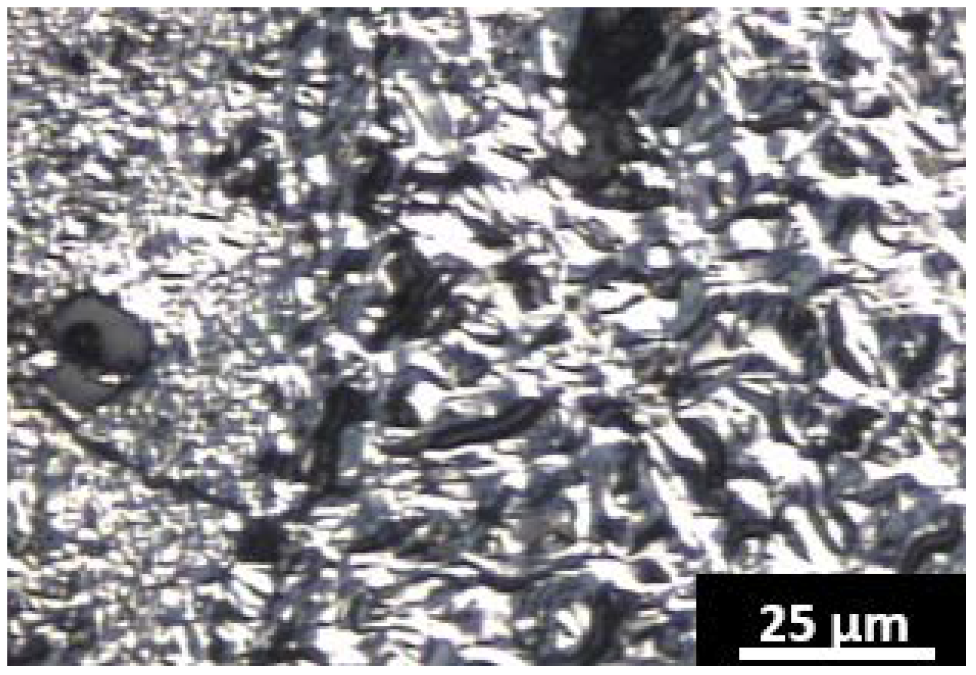
Anthracene goes through an extended mesophase during carbonization as evidenced by the high optical anisotropy shown in the polarized light micrograph, Figure 1. As such, anthracene coke is highly graphitizable and forms a synthetic graphite upon graphitization heat treatment [14,15,28,29]. Optical texture is classified in Appendix A.
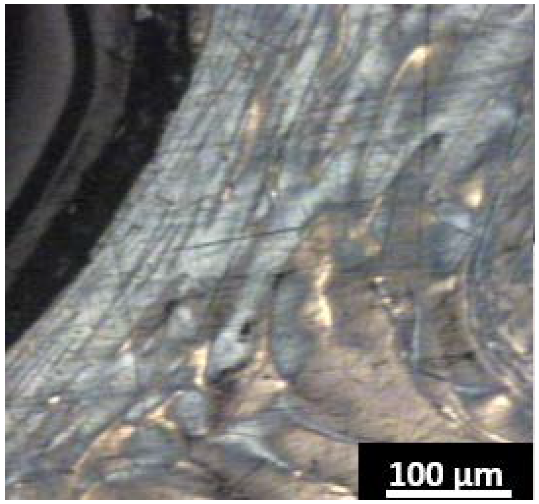
Fluorene, a five-membered ring containing PAH, yields only tar and no solid carbon after carbonization at 500 °C for 5 h. To maintain a prolonged fluid phase that promotes potential mesophase formation, fluorene was again carbonized at 500 °C and a solid carbon product was obtained after 12 h. The carbon yield was very high ~75% (anthracene coke ~50%). However, no optical anisotropy was observed under the polarized light microscope. The polarized light micrograph from fluorene char in 
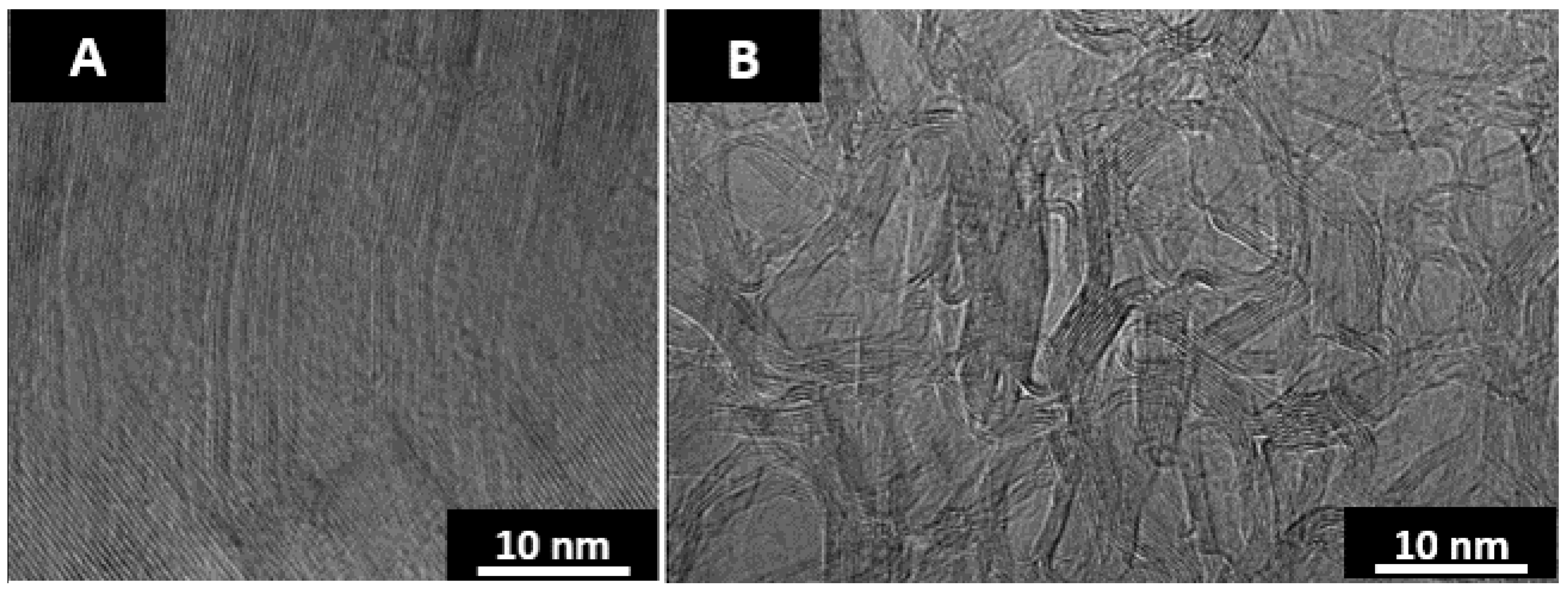
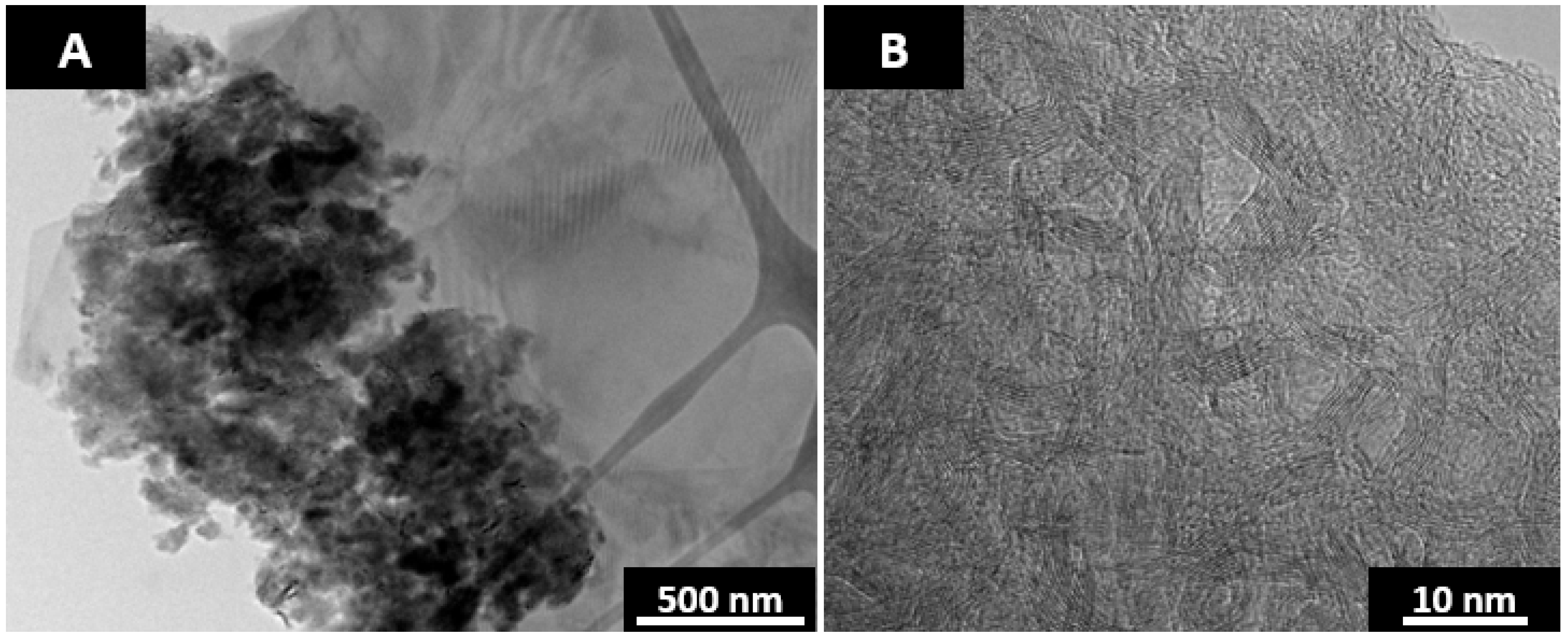
Figure 2 is absent of colored regions representative of anisotropy. The nanostructure of the 2 materials after furnace annealing at 2600 °C for 1 h is displayed by the TEM micrographs in Figure 3.
As seen in the TEM micrographs, anthracene coke is a highly ordered graphitic structure and fluorene char is a highly disordered material with a chaotic nanostructure. The curvature found in heat-treated fluorene char is believed to be due to the inclusion of curvature inducing pentagonal ring structures [30,31,32,33,34,35,36].
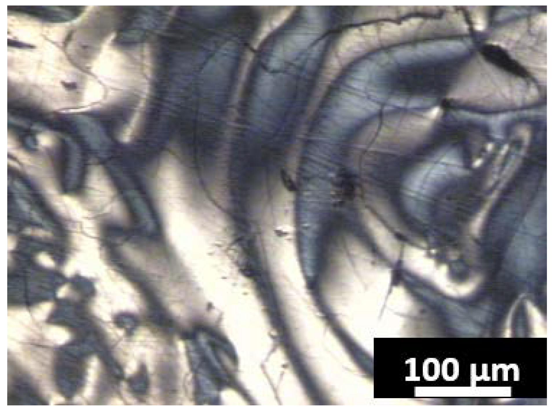
A 1:1 blend of fluorene and anthracene by weight was co-carbonized at 500 °C for 5 h. Due to the difference in reactivity of the compounds at 500 °C, it was expected that the surface would be heterogeneous and contain optical anisotropic regions formed from anthracene carbonization and pitch from fluorene carbonization. Indeed, pitch was found in abundant supply, shown on the edges of the micrograph in Figure 4 (black regions), as were abundant flow domains from anthracene.
It has been demonstrated that optical anisotropy is typically locked in place upon the completion of mesophase development [27]. However, heat treatment of the co-carbonized material partially destroyed the optical texture as shown in Figure 5. The optical textures after heat treatment at 2600 °C for 1 h are mosaics (left) and small domains (right). No flow domains were preserved upon heating and thus fluorene pitch must have been embedded in the flow domains in Figure 4. The smaller textures are the remnants of the original anthracene flow domains. At the nanoscale, clear heterogeneity exists, as shown in the TEM micrograph in Figure 6.
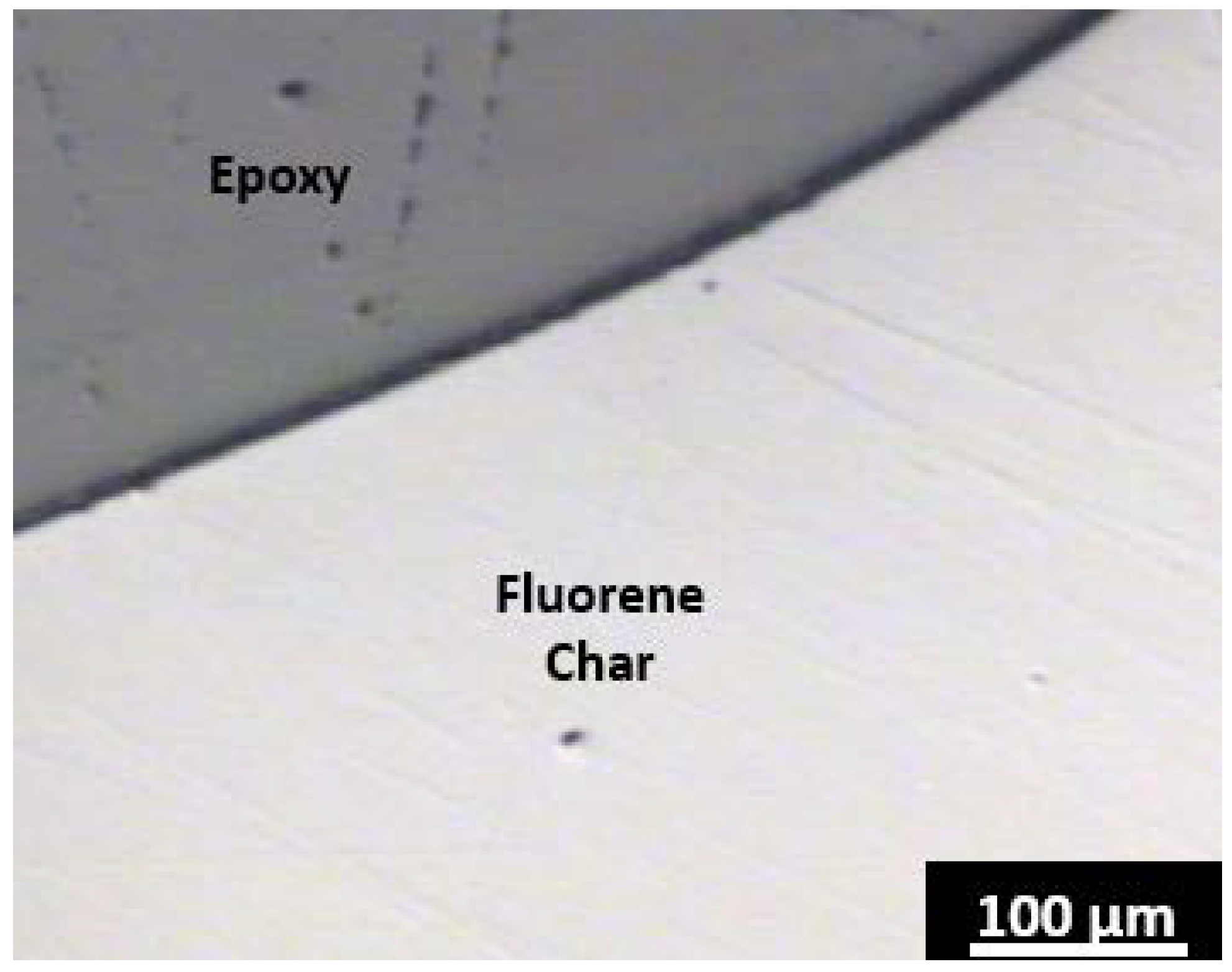
The 2 regions are anthracene coke derived synthetic graphite as displayed in the right hand side of Figure 6A and disordered regions as shown on the left in Figure 6A and with a higher magnification in Figure 6B. The disordered regions were likely present in the virgin coke as fluorene derived pitch. Since the disordered regions shown in the TEM micrograph are below the detection size limit of a light microscope, pitch was not observed dispersed throughout the flow domains in Figure 4. The structure of the disordered region is very similar to that observed from heat-treated fluorene char. Upon furnace heat treatment, the pitch forms the disordered carbon regions causing stress between adjacent graphitic regions that results in misalignment. This misalignment translates to a decreased optical texture size as observed in the polarized light micrographs from before and after heat treatment.
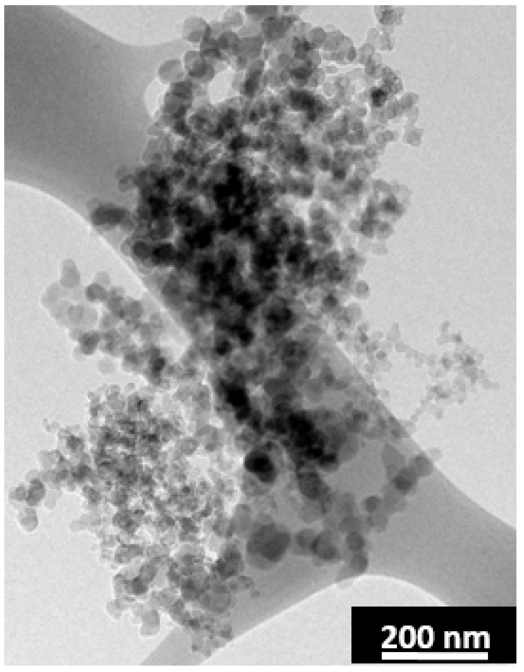
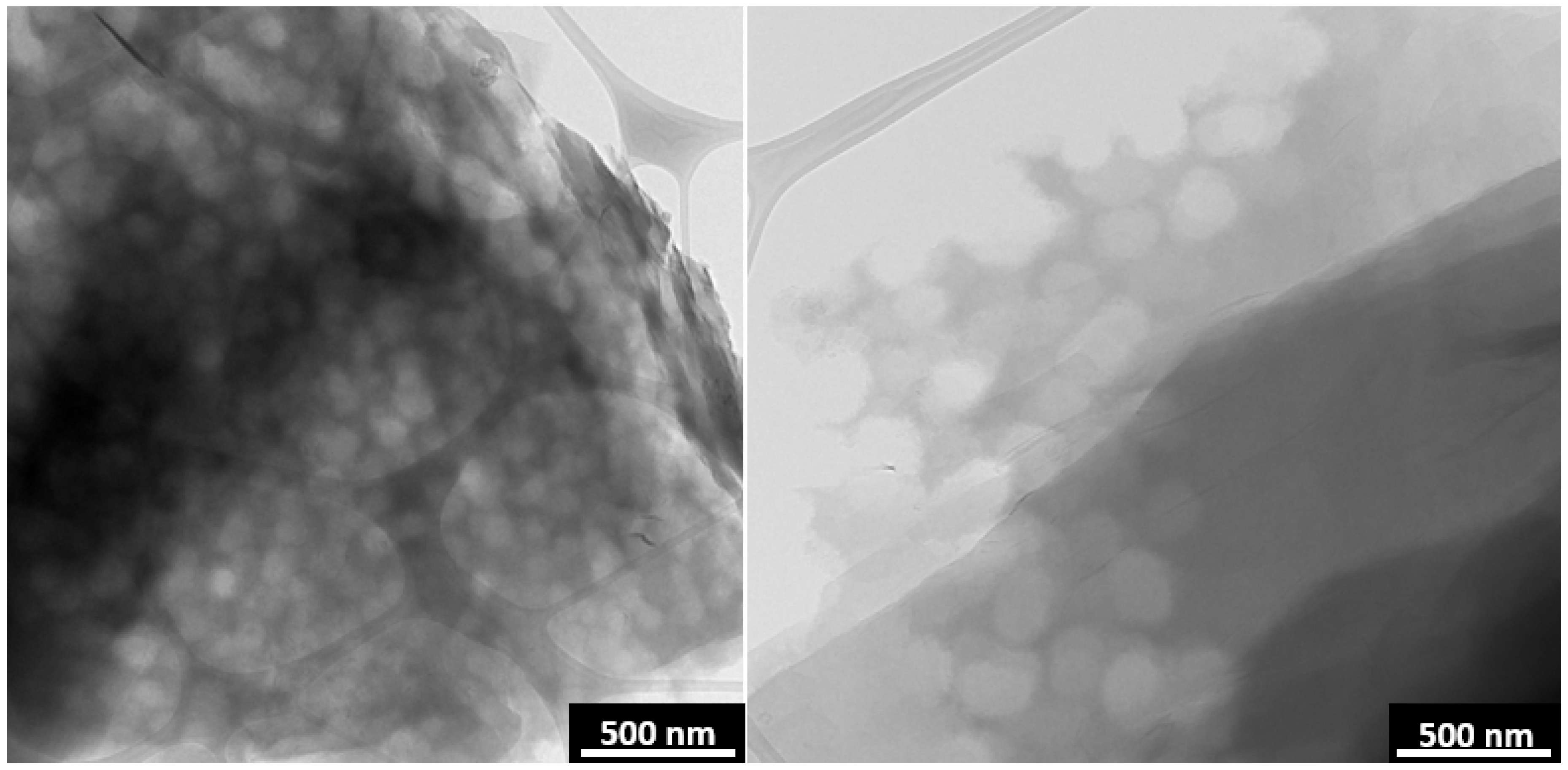
CO2 laser annealing vaporizes out the fluorene derived pitch while annealing the anthracene coke. The resulting structure is that of graphite with ~200 nm spherical pores as shown in Figure 7. The Swiss cheese like structure in Figure 7 was prepared by CO2 laser annealing at 2600 °C for a duration of 1 min. Traditional furnace annealing of this material does not result in the porous structure as the heating rates are too slow to vaporize out the pitch. The heating rate of the CO2 laser is 1.8 × 10⁶ °C/s. The CO2 laser heating rates and experimental setup have been reported elsewhere [16].
The vaporization of the fluorene pitch is rapid and SCG is produced with very short laser pulses. Longer laser pulse widths are utilized to anneal the remaining anthracene coke. A thin carbon film from the deposition of the vaporized fluorene pitch was found around the annealed sample. A TEM grid was placed near the sample for the purpose of collecting the film. A TEM micrograph of the deposited carbon product is shown in Figure 8. The film is in the form of soot and thus supports the assumption of vaporized pitch leaving behind the pores as the pyrolysis of pitch in aerosol will result in the formation of soot [37,38].
After 1 min of CO2 laser annealing the SCG has a d002 spacing of 3.40 Å, the same as pure anthracene coke subjected to the same heat treatment and thus the pores do not limit graphitizability. The laser synthesized SCG was heat treated at 2600 °C for a 1 h duration in a graphitization furnace. The layer plane spacing reduced to 3.36 Å, the same as pure anthracene coke.
A potential application of porous SCG is to use it as a lithiated anode. Graphite is the most common anode material for lithium ion batteries. However, the rate capacity of charging and discharging the lithiated graphite anode is a limiting factor. The porous SCG may provide improved rate capacity as the pores can increase Li
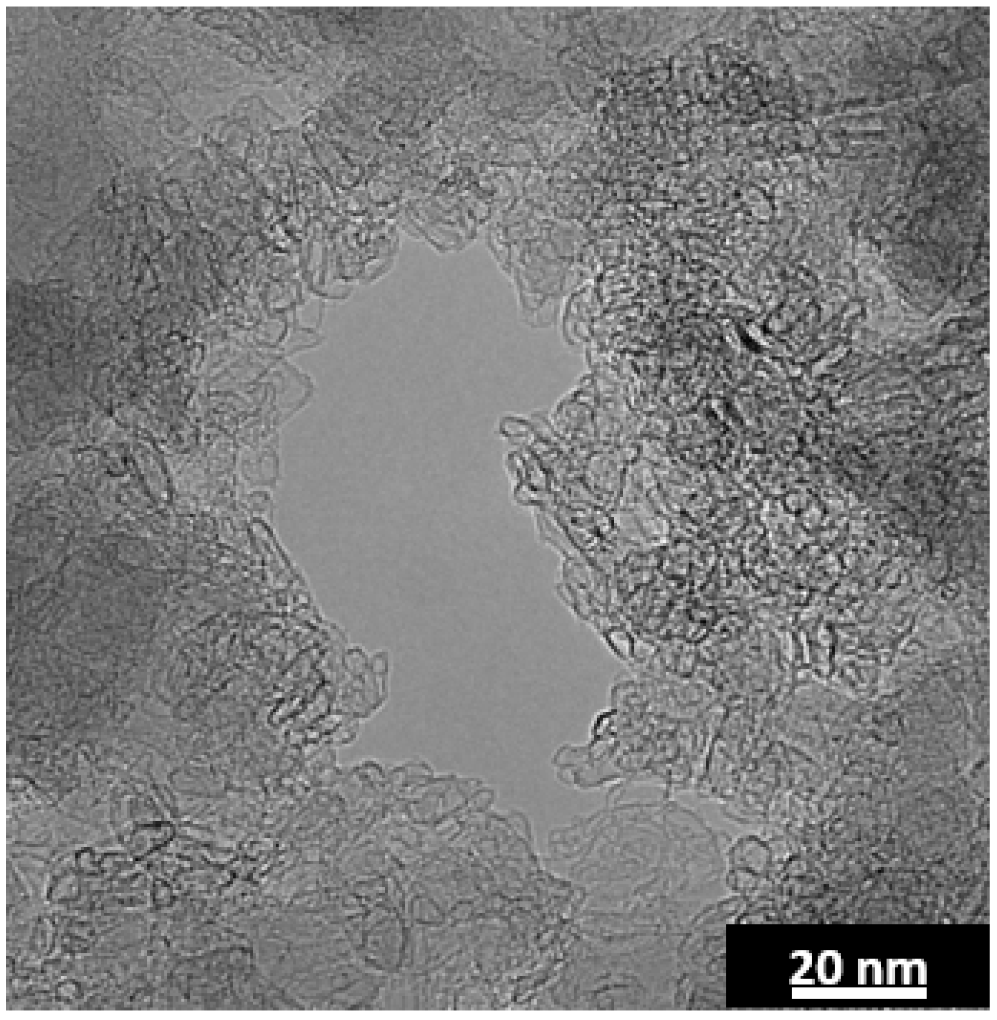
+ transport to the graphite gallery (edges), while improving their accessibility by increased exposure. Moreover, shorter interstitial distances (due to porosity) could also increase lithium intercalation and deintercalation rates, while retaining the desired properties of graphite (high energy density). The ideal porous graphite should contain pores covering the entire material and the graphite pore interface needs to be accessible to Li. However, as seen in the TEM micrograph in the right side of Figure 7, not all of the laser annealed anthracene-fluorene coke contains pores. The pores were found dispersed in only ~1/4 of the material. Additionally, the pore walls are comprised of closed shell nanoparticles and thus the graphitic layers are inaccessible to Li ions (Figure 9).
In an attempt to optimize SCG, fluorene was replaced with pyrene as the fullerene-like structures around the pore walls may likely be due to the odd-membered ring. It has been repeatedly observed that oils with higher concentrations of pyrene result in extended fluidity of the carbonization medium [4,39,40,
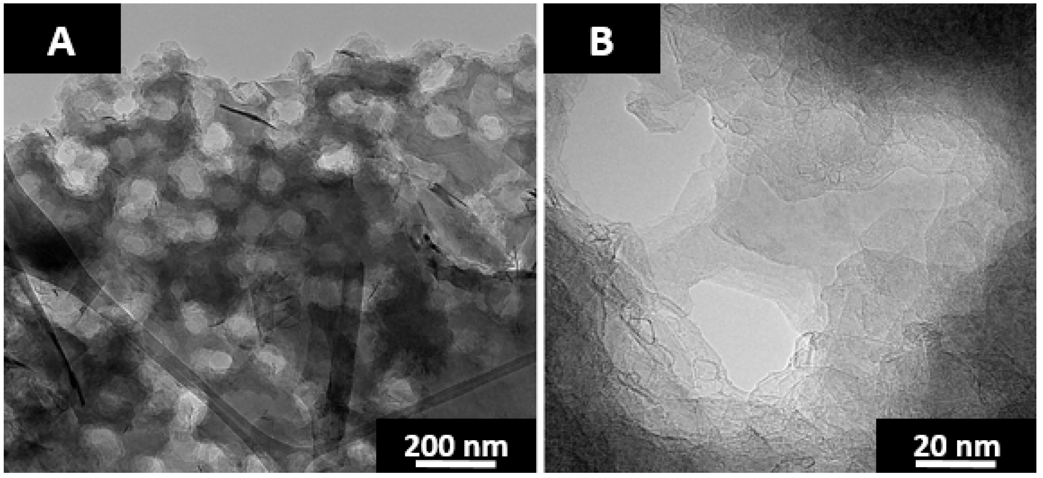
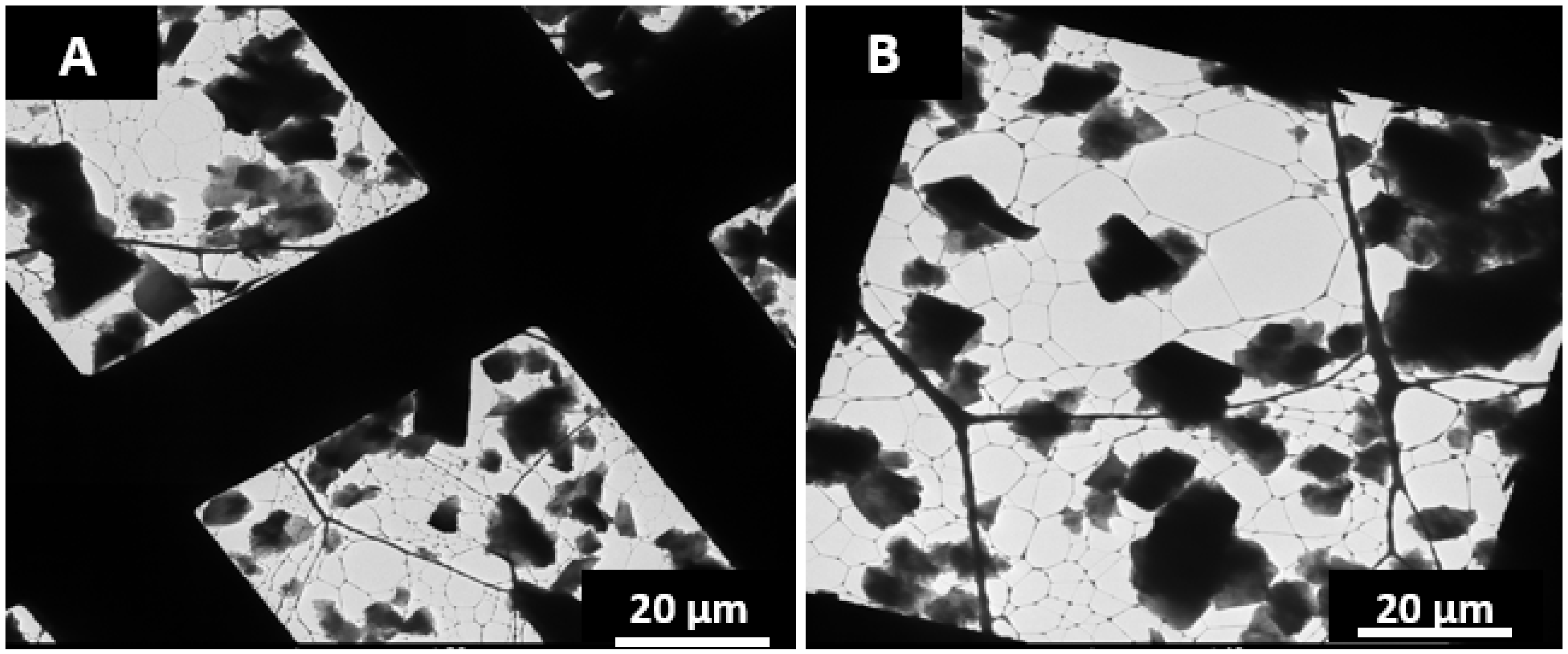
41]. Pyrene functions as a hydrogen shuttler and good solvent, extending fluidity and moderating the reactivity of the carbonizing medium. Co-carbonization of pyrene and anthracene yielded mostly tar after 5 h at 500 °C. The recovered solid product was 10% weight of that of the starting feed and did not yield SCG upon laser annealing as the pitch did not disperse throughout the solid. Co-carbonization of an equal part blend by weight of anthracene-fluorene-pyrene yielded 30% weight of solid carbon after carbonization at 500 °C for 5 h and resulted in SCG upon laser heating. The laser annealed product is shown in the TEM micrograph in Figure 10. As seen in Figure 10B, the graphitic layer planes are for the most part unimpeded with relatively few fullerene-like nanoparticles lining the pore walls. The reduction in fullerene-like particles may reflect the reduction in concentration of curvature inducing pentagonal ring systems. However, their nearly complete absence suggests otherwise. Pyrene mediated carbonization may create a boundary layer between the fluorene pitch and anthracene coke.
Pore coverage was increased to greater than half of the material by providing vertical agitation of the reactors at a frequency of 200 oscillations a minute and an amplitude of 2.5 cm. The pore diameter is ~100 nm with reactor agitation as shown in Figure 10A, compared to ~200 nm w/out agitation and ~1/4 material coverage. Increasing the frequency beyond 200 oscillations a minute did not result in increased pore coverage. The crystal lattice dimensions of pure anthracene coke and SCG after furnace heat treatment at 2600 °C for 1 h are provided in Table 1 as measured by XRD.
The carbon layer diameter (La) and stack height (Lc) are reduced due to the pores in SCG as compared to heat-treated anthracene coke. The lattice spacing and thus degree of graphitization are the same between the materials. Therefore, SCG is graphitized anthracene coke that contains quasi-spherical pores. Pore shape is assumed to be quasi-spherical based on the thickness contrast of the TEM micrographs in Figure 10. The BET surface area was measured from both heat-treated anthracene coke and SCG after ball milling for 30 min. A TEM survey showed that both materials have an equivalent particle size of ~10 μm (micrographs provided in Appendix B). The surface areas of SCG and heat-treated anthracene coke are 30 and 8 m
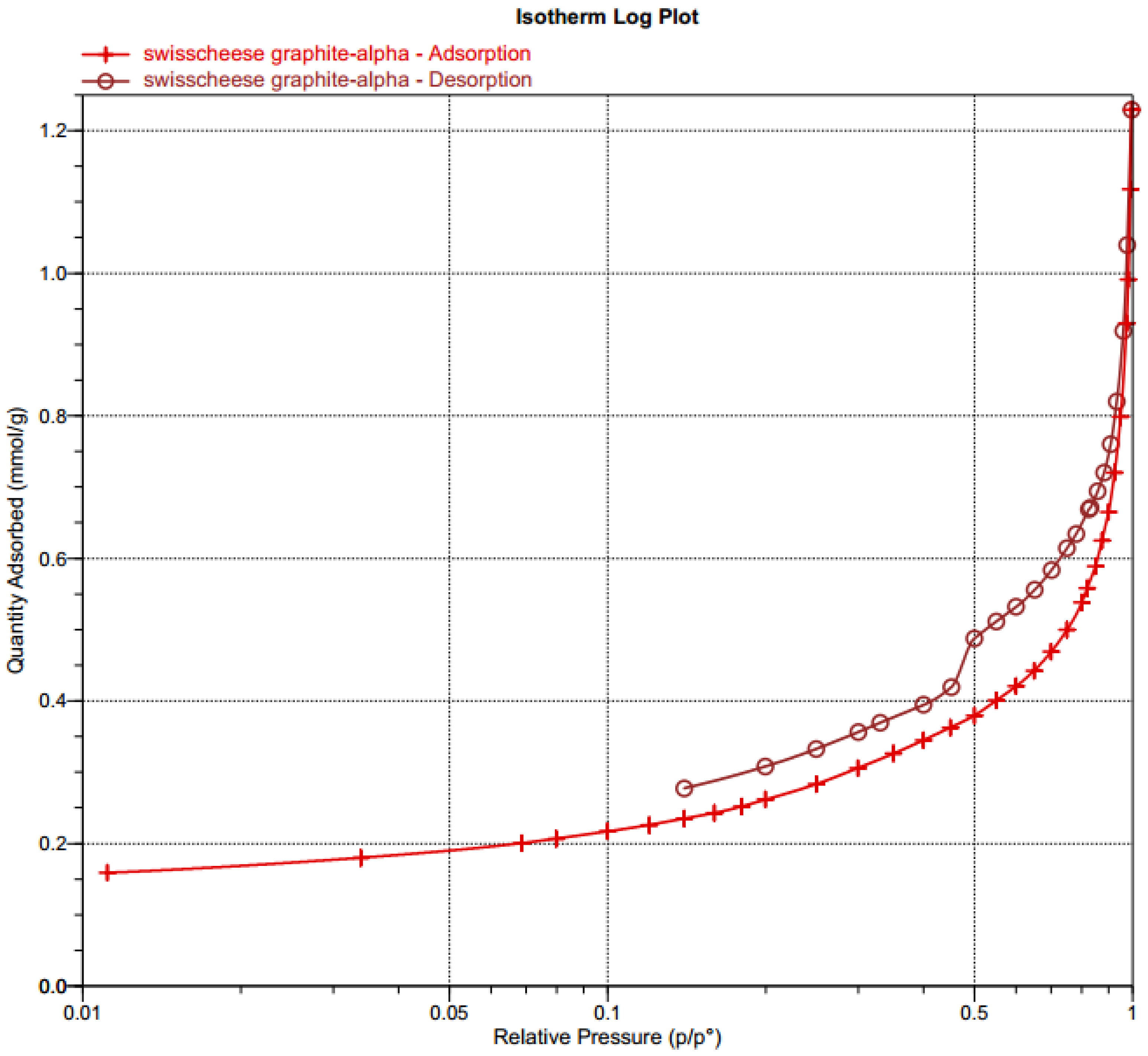
2/g, respectively. The nearly 4-fold greater surface area of SCG reflects the pores, considering the particle sizes of the 2 materials are equivalent. The total pore volume of SCG is 0.45 cm3/g, the N2 isotherm is provided in Appendix C.
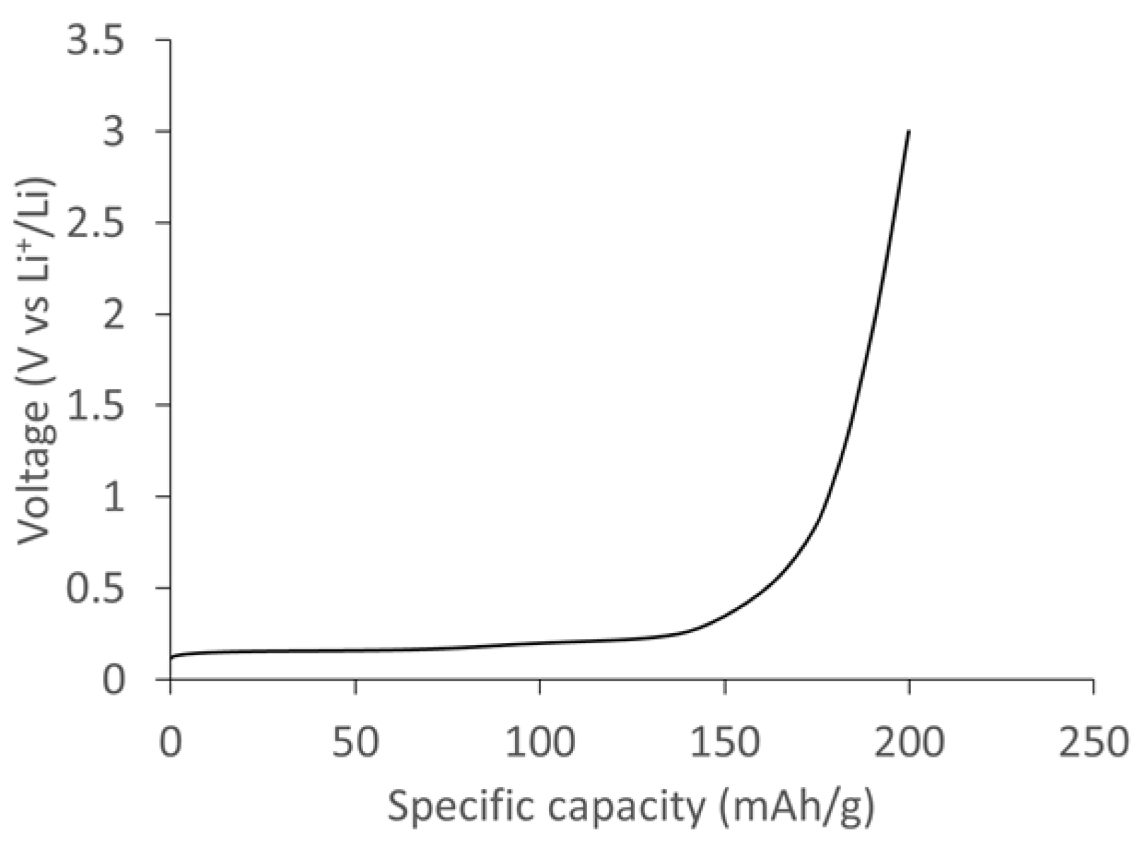
The optimized SCG was prelithiated using a short circuiting approach. The specific capacity of the SCG electrode was measured using half-cell measurements by delithiating the SCG electrode to 3 V.
Figure 11 shows the specific capacity of the SCG electrode measured at a current density of 0.1 A/g. The delithiation curve shows a voltage plateau below 0.2 V vs. Li+/Li corresponding to various stages of lithium deintercalation in SCG graphite. The total specific capacity measured at 0.1 A/g was ~235 mAh/g based on the active mass of SCG electrode. 
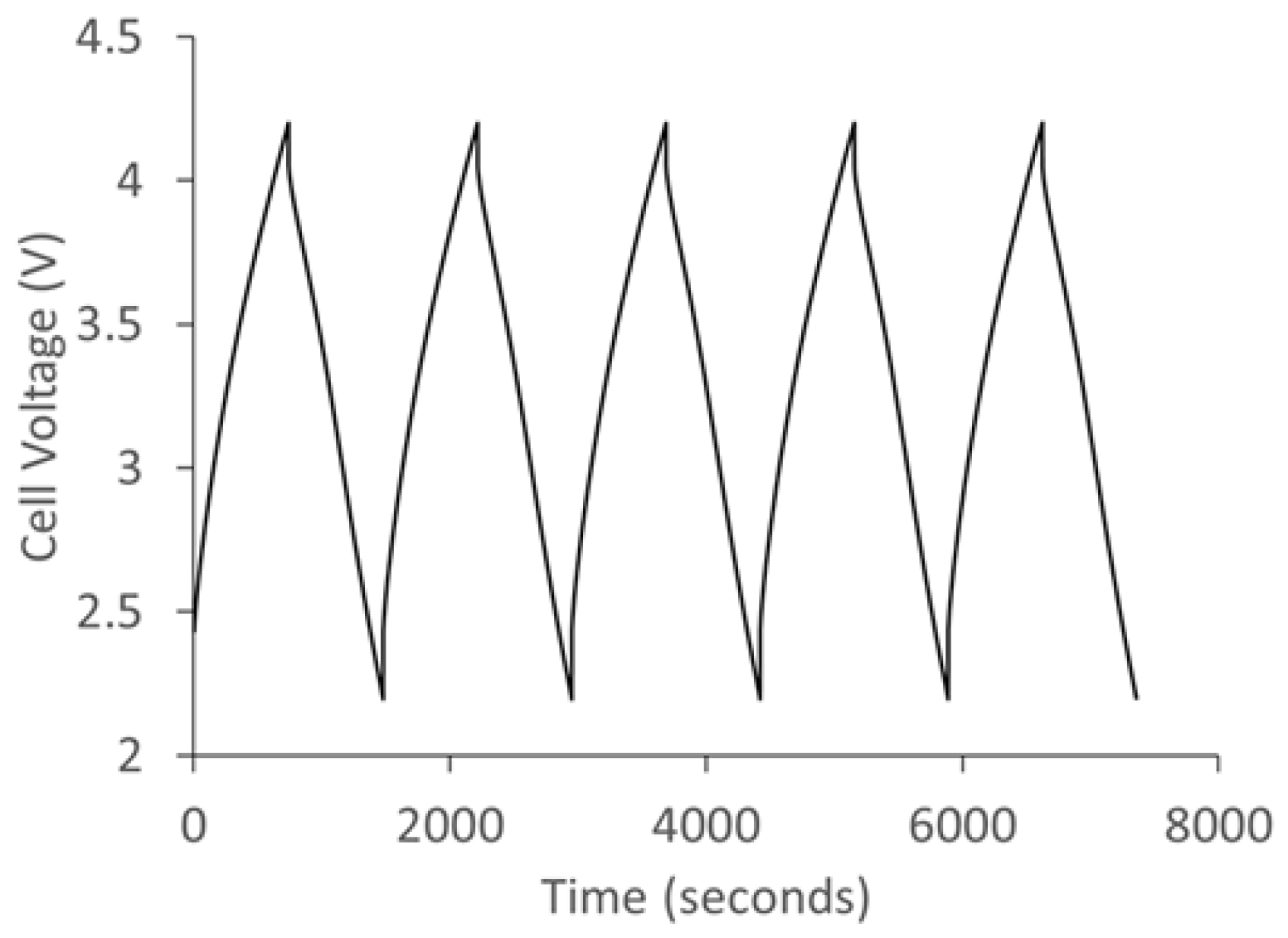
Figure 12 shows the charge/discharge curve of the lithium ion capacitor fabricated using polyfurfuryl alcohol/phloroglucinol carbon as cathode and prelithiated SCG as anode. The hybrid capacitor was cycled between 2.2 V and 4.2 V and exhibits a typical sawtooth profile. 
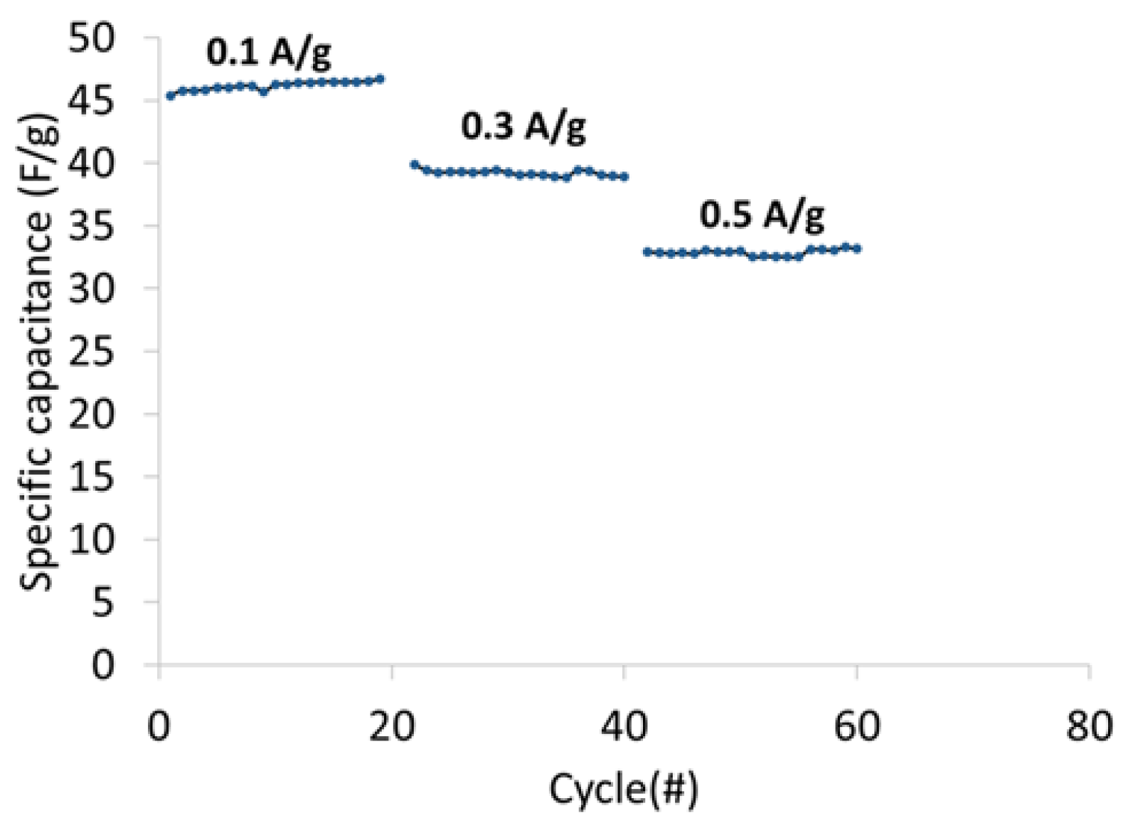
Figure 13 shows the specific cell capacitance plotted as a function of current density. The specific capacitance at 0.1 A/g, 0.3 A/g and 0.5 A/g was 46 F/g, 39 F/g, and 33 F/g, respectively. 
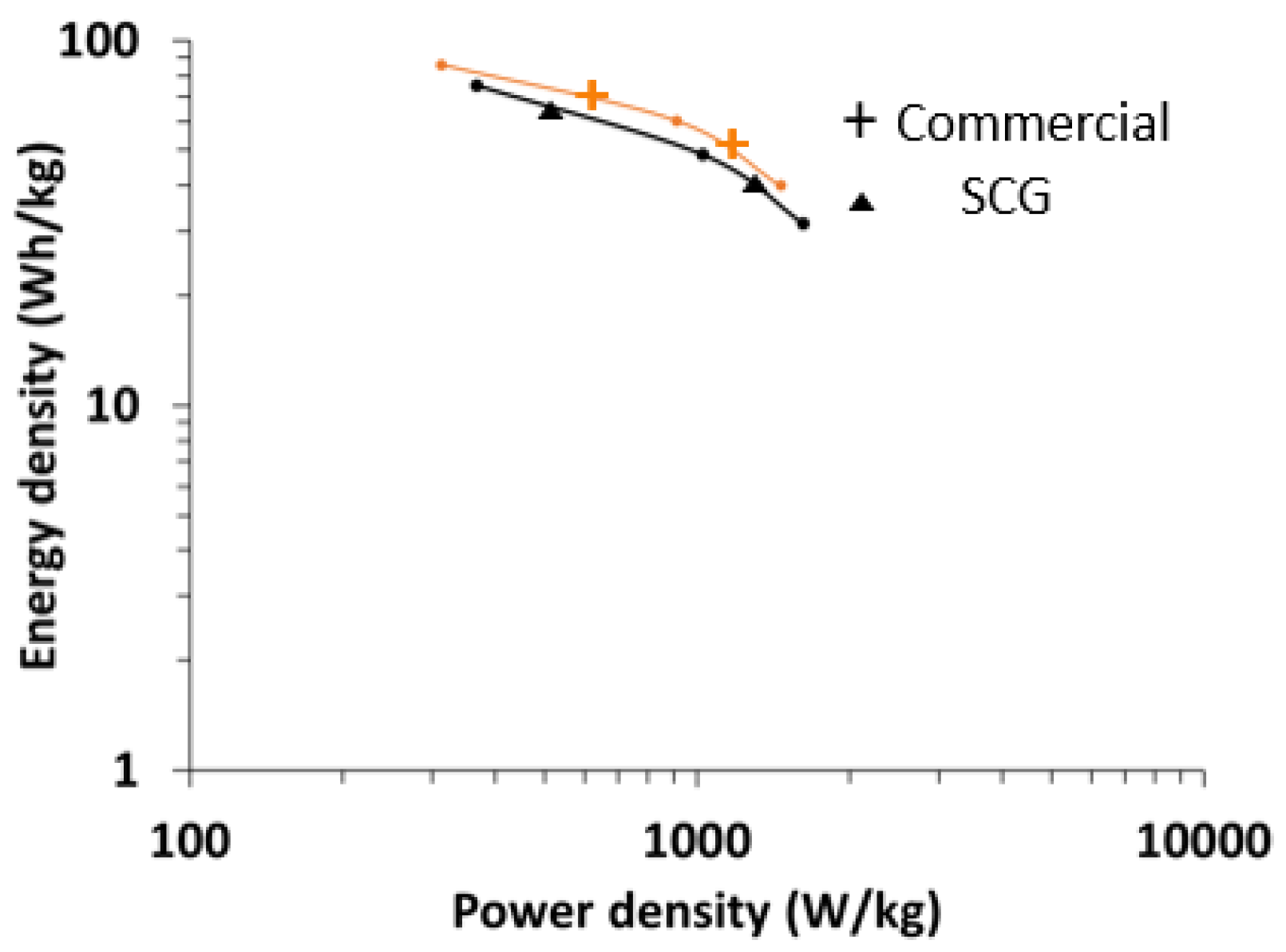
Figure 14 shows the comparison of the Ragone plot made using prelithiated SCG graphite and commercially available graphite derived from mesophase pitch. The energy density of the capacitor was ~75 Wh/kg at a power density of 370 W/kg. At 1 KW/kg, the energy density was about 48.5 Wh/kg.
In the current form, SCG does not provide improvement over commercial carbon anode materials. Although the relative surface area increase is large compared to pure anthracene derived graphite, 30 m2/g is low and likely a limiting factor. Further refinement of porosity and improvement in surface area, either pre-engineered by recipe and procedure or post partial activation, could result in increased rate capability and power characteristics. The low surface area of SCG is attributed to limited pore coverage. Approximately half of the material is non-porous. Pore coverage increased from ~1/4 to greater than half of the material by providing vertical agitation of the reactors. Increased vertical agitation beyond 200 oscillations a minute at an amplitude of 2.5 cm did not provide increased surface area. A potential method to increase surface area is to provide horizontal agitation of the reactor during carbonization. Horizontal agitation may result in the higher dispersion of the fluorene derived liquid pitch throughout the anthracene derived coke. Recipe modification is another avenue to explore, increasing the pitch precursor (fluorene) would decrease solid product yield, but may provide a more porous material with higher surface area. Other low carbonization reactivity compounds that yield pitch should be experimented with, in place and in combinations with fluorene and pyrene.
The electrical properties do demonstrate the graphitic nature of SCG. Thus, SCG is a porous graphite synthesized directly from tailored carbonization products via rapid thermal processing. Rapid thermal processing bypasses the need for templating and template removal. Laser annealing carbon is potentially of enormous technological importance as synthesis not possible via traditional annealing can be used in the development of novel materials like SCG. The pores in SCG provide access to the graphite gallery (edges), whereas templated carbons align normally to the template and thus block edge access.

4. Conclusions

Porous Swiss-Cheese-Graphite (SCG) was prepared by rapidly heating the carbonization product of an equal part blend of anthracene, fluorene, and pyrene with a CO2 laser. Rapid CO2 laser heating at a rate of 1.8 × 10⁶ °C/s vaporized out the fluorene-pyrene derived pitch while annealing the anthracene coke. The resulting structure is that of graphite with 100 nm spherical pores. The graphitizablity of SCG is the same as pure anthracene coke. A TEM investigation paired with an electrical half-cell test shows that interfaces between graphitic layers and the pore wall are unimpeded. SCG was prelithiated and tested as an anode in lithium ion capacitors. The fabricated capacitor showed good voltage stability between 2.2 V and 4.2 V and an energy density as high as 75 Wh/kg.

Author Contributions

Joseph P. Abrahamson and Randy L. Vander Wal conceived and designed the experiments related to the material synthesis; Joseph Abrahamson performed the experiments and material characterization; Ramakrishnan Rajagopalan conceived, designed, and preformed the electrochemical experiment; Joseph Abrahamson wrote the paper.

Funding

This research was funded by NSF CBET grant number 1236757.

Acknowledgments

This work was supported by the NSF CBET, Grant No. 1236757 with the Pennsylvania State University, University Park, PA 16802.

Conflicts of Interest

The authors declare no conflict of interest.

Appendix A. Optical Texture

The optical textures of anthracene coke are mainly flow domains and domains; optical texture sizes are classified in reference [42]. Domains (often further classified as small and large) refer to anisotropic regions with diameters between 10–60 µm. Elongated domains that are greater than 60 µm in length and greater than 10 µm in width are called flow domains. Mosaics describes small structures of anisotropic units that are 1–10 µm in diameter (smallest resolvable optical textures in a light microscope). A preponderance of a given texture, or a mixture of textures, characterizes the principal optical texture of cokes.

Appendix B. Particle Size

Figure A1. TEM micrographs of (A) Swiss-Cheese-Graphite after 30 min of ball mill and (B) heat-treated anthracene coke after 30 min of ball milling.
Carbon 04 00027 g0a1

Appendix C. N2 Isotherm

Figure A2. N2 isotherm of SCG.
Carbon 04 00027 g0a2

References

  1. Eser, S.; Jenkins, R.G.; Derbyshire, F.J. Carbonization of coker feedstocks and their fractions. Carbon 1986, 24, 77–82. [Google Scholar] [CrossRef]
  2. Marsh, H.; Martínez-Escandell, M.; Rodríguez-Reinoso, F. Semicokes from pitch pyrolysis: Mechanisms and kinetics. Carbon 1999, 37, 363–390. [Google Scholar] [CrossRef]
  3. Eser, S.; Jenkins, R.G. Carbonization of petroleum feedstocks II: Chemical constitution of feedstock asphaltenes and mesophase development. Carbon 1989, 27, 889–897. [Google Scholar] [CrossRef]
  4. Wang, G.; Eser, S. Molecular composition of the high-boiling components of needle coke feedstocks and mesophase development. Energy Fuels 2007, 21, 3563–3572. [Google Scholar] [CrossRef]
  5. Taylor, G.H. Development of optical properties of coke during carbonization. Fuel 1961, 40, 465–471. [Google Scholar]
  6. Lewis, I. Chemistry of carbonization. Carbon 1982, 20, 519–529. [Google Scholar] [CrossRef]
  7. Walker, P.L. Carbon: An old but new material revisited. Carbon 1990, 28, 261–279. [Google Scholar] [CrossRef]
  8. Eser, S.; Andresen, J.M. Properties of fuels, petroleum pitch, petroleum coke, and carbon materials. In Fuels and Lubricants Handbook: Technology, Properties, Performance, and Testing; Totten, G.E., Ed.; ASTM International: West Conshohcken, PA, USA, 2003; pp. 757–787. [Google Scholar]
  9. Newcomb, B.A. Processing, structure, and properties of carbon fibers. Compos. Part A Appl. Sci. Manuf. 2016, 91, 262–282. [Google Scholar] [CrossRef]
  10. Singer, L.S. The mesophase and high modulus carbon fiber from pitch. Carbon 1977, 16, 409–415. [Google Scholar] [CrossRef]
  11. Lee, J.; Kim, J.; Hyeon, T. Recent progress in the synthesis of porous carbon materials. Adv. Mater. 2006, 18, 2073–2094. [Google Scholar] [CrossRef]
  12. Hu, Y.S.; Adelhelm, P.; Smarsly, B.M.; Hore, S.; Antonietti, M.; Maier, J. Synthesis of hierarchically porous carbon monoliths with highly ordered microstructure and their application in rechargeable lithium batteries with high-rate capability. Adv. Funct. Mater. 2007, 17, 1873–1878. [Google Scholar] [CrossRef]
  13. Walker, P.L. Carbon an old but new material (George Skakel Award Lecture). Carbon 1972, 10. [Google Scholar] [CrossRef]
  14. Scaroni, A.W.; Jenkins, R.G.; Walker, P.L. Carbonization of anthracene in a batch reactor. Carbon 1991, 29, 969–980. [Google Scholar] [CrossRef]
  15. Peters, T.J.; Jenkins, R.G.; Scaroni, A.W.; Walker, P.L. The importance of carbonization conditions on the character of phenanthrene coke and its graphitizability. Carbon 1991, 29, 981–990. [Google Scholar] [CrossRef]
  16. Abrahamson, J.P.; Madhu, S.; Mathews, J.P.; Vander Wal, R.L. Pulsed laser annealing of carbon black. Carbon 2017, 124, 380–390. [Google Scholar] [CrossRef]
  17. Vlad, A.; Singh, N.; Rolland, J.; Melinte, S.; Ajayan, P.M.; Gohy, J.-F. Hybrid supercapacitor-battery materials for fast electrochemical charge storage. Sci. Rep. 2014, 4, 4315. [Google Scholar] [CrossRef] [PubMed]
  18. Peer, M.; Qajar, A.; Rajagopalan, R.; Foley, H.C. Synthesis of carbon with bimodal porosity by simultaneous polymerization of furfuryl alcohol and phloroglucinol. Microporous Mesoporous Mater. 2014, 196, 235–242. [Google Scholar] [CrossRef]
  19. Qu, W.; Dorjpalam, E.; Rajagopalan, R.; Randall, C.A. Role of additives in formation of solid-electrolyte interfaces on carbon electrodes and their effect on high-voltage stability. ChemSusChem 2014, 7, 1162–1169. [Google Scholar] [CrossRef] [PubMed]
  20. Cericola, D.; Kötz, R. Hybridization of rechargeable batteries and electrochemical capacitors: Principles and limits. Electrochim. Acta 2012, 72, 1–17. [Google Scholar] [CrossRef]
  21. Simon, P.; Gogotsi, Y.; Dunn, B. Where do batteries end and supercapacitors begin? Science 2014, 343, 1210–1211. [Google Scholar] [CrossRef] [PubMed] [Green Version]
  22. Yang, W.; Yang, W.; Ding, F.; Sang, L.; Ma, Z.; Shao, G. Template-free synthesis of ultrathin porous carbon shell with excellent conductivity for high-rate supercapacitors. Carbon 2017, 111, 419–427. [Google Scholar] [CrossRef]
  23. Zhang, H.; Cooper, A.I. Synthesis and applications of emulsion-templated porous materials. Soft Matter 2005, 1, 107–113. [Google Scholar] [CrossRef]
  24. Woodward, R.T.; Markoulidis, F.; De Luca, F.; Anthony, D.B.; Malko, D.; McDonald, T.O.; Shaffer, M.S.P.; Bismarck, A. Carbon foams from emulsion-templated reduced graphene oxide polymer composites: Electrodes for supercapacitor devices. J. Mater. Chem. A 2018, 1840–1849. [Google Scholar] [CrossRef]
  25. Sakintuna, B.; Yürüm, Y. Templated Porous Carbons: A Review Article. Ind. Eng. Chem. Res. 2005, 44, 2893–2902. [Google Scholar] [CrossRef]
  26. Knox, J.H.; Kaur, B.; Millward, G.R. Structure and performance of porous graphitic carbon in liquid chromatography. J. Chromatogr. A 1986, 352, 3–25. [Google Scholar] [CrossRef]
  27. Abrahamson, J.P.; Jain, A.; van Duin, A.C.T.; Vander Wal, R.L. Carbon structure and resulting graphitizability upon oxygen evolution. Carbon 2018, in press. [Google Scholar] [CrossRef]
  28. Rouzaud, J.N.; Oberlin, A. Structure, microtexture, and optical properties of anthracene and saccharose-based carbons. Carbon 1989, 27, 517–529. [Google Scholar] [CrossRef]
  29. Kinney, C.R.; Nunn, R.C.; Walker, P.L. Carbonization of anthracene and graphitization of anthracene carbons. Ind. Eng. Chem. 1957, 49, 880–884. [Google Scholar] [CrossRef]
  30. Harris, P.J.F. New perspectives on the structure of graphitic carbons. Crit. Rev. Solid State Mater. Sci. 2005, 30, 235–253. [Google Scholar] [CrossRef]
  31. Harris, P.J.F.; Tsang, S.C. High-resolution electron microscopy studies of non-graphitizing carbons. Philos. Mag. A Phys. Condens. Matter Struct. Defects Mech. Prop. 1997, 76, 667–677. [Google Scholar] [CrossRef]
  32. Harris, P.J.F. Impact of fullerenes on carbon science. In Chemistry and Physics of Carbon; Radovic, L.R., Ed.; Marcel Dekker, Inc.: New York, NY, USA, 2003; pp. 1–36. [Google Scholar]
  33. Harris, P.J.F. Fullerene-related structure of commercial glassy carbons. Philos. Mag. 2004, 84, 3159–3167. [Google Scholar] [CrossRef]
  34. Harris, P.J.F. Structure of non-graphitising carbons. Int. Mater. Rev. 1997, 42, 206–218. [Google Scholar] [CrossRef]
  35. Leyssale, J.-M.; Da Costa, J.-P.; Germain, C.; Weisbecker, P.; Vignoles, G.L. Structural features of pyrocarbon atomistic models constructed from transmission electron microscopy images. Carbon 2012, 50, 4388–4400. [Google Scholar] [CrossRef] [Green Version]
  36. Wang, C.; Huddle, T.; Huang, C.H.; Zhu, W.; Vander Wal, R.L.; Lester, E.H.; Mathews, J.P. Improved quantification of curvature in high-resolution transmission electron microscopy lattice fringe micrographs of soots. Carbon 2017, 117, 174–181. [Google Scholar] [CrossRef]
  37. Apicella, B.; Carpentieri, A.; Alfè, M.; Barbella, R.; Tregrossi, A.; Pucci, P.; Ciajolo, A. Mass spectrometric analysis of large PAH in a fuel-rich ethylene flame. Proc. Combust. Inst. 2007, 31, 547–553. [Google Scholar] [CrossRef]
  38. Alfè, M.; Apicella, B.; Tregrossi, A.; Ciajolo, A. Identification of large polycyclic aromatic hydrocarbons in carbon particulates formed in a fuel-rich premixed ethylene flame. Carbon 2008, 46, 2059–2066. [Google Scholar] [CrossRef]
  39. Filley, R.M.; Eser, S. Analysis of hydrocarbons and sulfur compounds in two FCC decant oils and their carbonization products. Energy Fuels 1997, 11, 623–630. [Google Scholar] [CrossRef]
  40. Abrahamson, J.P.; Wincek, R.T.; Eser, S. Scheme for Hydrotreatment of fluid catalytic cracking decant oil with reduced hydrogen consumption and high needle coke yield upon carbonization. Energy Fuels 2016, 30, 8150–8155. [Google Scholar] [CrossRef]
  41. Wincek, R.T.; Abrahamson, J.P.; Eser, S. Hydrodesulfurization of fluid catalytic cracking decant oils in a laboratory flow reactor and effect of hydrodesulfurization on subsequent coking. Energy Fuels 2016, 30, 6281–6289. [Google Scholar] [CrossRef]
  42. Eser, S. Carbonaceous mesophase formation and molecular composition of petroleum feedstocks. In Supercarbon: Synthesis, Properties and Applications; Yoshimura, S., Chang, R.P.H., Eds.; Springer: New York, NY, USA, 1998; pp. 147–155. [Google Scholar]
Figure 1. Polarized light micrograph of anthracene coke.
Carbon 04 00027 g001
Figure 2. Polarized light micrograph of fluorene char.
Carbon 04 00027 g002
Figure 3. TEM micrographs of (A) anthracene coke and (B) fluorene char after furnace heat treatment at 2600 °C for 1 h.
Carbon 04 00027 g003
Figure 4. Polarized light micrograph of co-carbonized anthracene-fluorene.
Carbon 04 00027 g004
Figure 5. Polarized light micrograph of anthracene-fluorene coke after furnace heat treatment at 2600 °C for 1 h.
Carbon 04 00027 g005
Figure 6. TEM micrographs of anthracene-fluorene coke—2600 °C, 1 h.
Carbon 04 00027 g006
Figure 7. TEM micrographs of Swiss-Cheese-Graphite formed from CO2 laser annealing of anthracene-fluorene coke.
Carbon 04 00027 g007
Figure 8. Soot formed from CO2 laser vaporization of fluorene carbonization pitch.
Carbon 04 00027 g008
Figure 9. TEM micrograph of pore wall from anthracene-fluorene derived porous graphite.
Carbon 04 00027 g009
Figure 10. TEM micrographs of CO2 laser heated (A) anthracene-fluorene–pyrene coke and (B) pore structure.
Carbon 04 00027 g010
Figure 11. Delithiation capacity of prelithiated SCG electrode measured at a current density of 0.1 A/g when cycled between 0.01 and 3 V vs. Li+/Li.
Carbon 04 00027 g011
Figure 12. Galvanostatic charge/discharge curve of lithium ion capacitor cycled between 2.2 V and 4.2 V at 0.1 A/g.
Carbon 04 00027 g012
Figure 13. Specific cell capacitance as a function of applied current density.
Carbon 04 00027 g013
Figure 14. Comparison of Ragone plot performance of lithium ion capacitor made using prelithiated SCG Graphite and commercial graphite as anode.
Carbon 04 00027 g014
Table 1. XRD crystal structure of anthracene coke and SCG—2600 °C, 1 h.
Anthracene CokeSCG
La [nm] from (110)11054
Lc [nm] from (002)6120
d002 [Å]3.363.36

