1. Introduction
Lithium-ion batteries (LIBs) are widely used for many industrial products currently. The purpose of this research is to develop high capacity anode electrode materials for LIB. It is necessary to obtain much higher capacity than the theoretical capacity for graphite since much wider utilization of LIBs is expected in the future. For the achievement of this purpose, carbon nanofibers containing Si nanoparticles and its components are created.
The alloy-type anode electrode material using Si has the largest charging/discharging capacity among the materials examined so far (4200 mAh/g), ≥10 times than that of graphite [
1]. There are, however, some problems when Si is adopted as an anode material. The volume of Si increases by 300–400% when Li is inserted into Si during charging. The repetition of these charging/discharging cycles generates a large amount of stress in the anode electrode material, and it causes the destruction of the electrode. In this research, we overcome these problems by wrapping Si nanoparticles using the carbon nanofibers.
2. Materials and Methods
2.1. Carbon Nanofibers Synthesized via Electrospinning
In this research, carbon nanofibers containing dissimilar materials were created by electrospinning method and some heat treatments. Preparation of the carbon nanofibers via electrospinning process is listed in
Table 1 [
2]. As a carbon precursor, PAN (polyacrylonitrile) was adopted since it has been used in the production of commercial carbon fibers. In addition, DMF (
N,
N-dimethylformamide) was used as a solvent. TEOS (tetraethoxysilane, chemical formula; SiC
8H
20O
4) and Si nanoparticles were mixed in PAN/DMF solution as additives. The Si nanoparticles were, incidentally, carbon-coated Si, i.e., a thin carbon layer (2–3 nm) surrounded the surface of the Si nanoparticles [
3].
To increase the heat resistance of the materials, stabilization processes at 240 °C or 260 °C in air were applied. Afterwards, the stabilized nanofibers were carbonized in N2 atmosphere at 700 °C or 1000 °C. Carbon nanofibers containing dissimilar materials were finally created.
2.2. Characterization of Carbon Nanofibers
Structures of the carbon nanofibers were observed by scanning electron microscopy (SEM, HITACHI, SU3500, Tokyo, Japan), energy dispersive X-ray diffraction (EDX, Oxford Instruments, X-Max, Abingdon, UK) and transmission electron microscopy (TEM, JEOL, JEM2100F, Tokyo, Japan). In addition, precise structures of the materials were determined using X-ray diffraction (XRD, Rigaku, SmartLab, Tokyo, Japan) and Raman scattering equipment (Kaiser, Hololab, Ann Arbor, MI, USA).
2.3. Electrochemical Characterization
2.3.1. Electrode Made of Nickel Mesh
Pulverized carbon nanofibers, vapor-grown carbon fiber (VGCF, Showa Denko K.K.) and polyvinylidene difluoride (PVDF) were mixed and they were settled on the nickel (Ni) mesh. The mixing ratio of VGCF was 10% of the carbon nanofibers. The mixing ratio of PVDF to the carbon nanofibers and VGCF was 1:1. After the settlement, the sample was pressurized at 10 MPa for 5 min. The cell and separator were CR2032-type and TF4850-type, respectively. For electrochemical experiments of the coin cell, constant current (CC) charging/discharging was adopted in this experiment. Current density was 30 mA/g, and charging/discharging processes ceased at 1 mV.
2.3.2. Electrode Made of Cupper Foil
Pulverized carbon nanofibers, carbon black (DENKA Black) and polyimide (varnish A) were mixed in the ratio of 75:10:15 wt % and they were settled on the copper foil [
3]. Afterwards, drying process for 1–2 h in a vacuum at 100 °C was carried out and it was then transferred to an electric furnace for calcination under flowing argon (flow rate; 500 cm
3/min). After finishing the calcination, the electrochemical sample was cut into a
Φ1.4 cm disc and dried for 24 h in a vacuum at 100 °C. It was then moved into an argon glove box to prepare a CR2032-type coin battery. Ethylene carbonate (EC)/diethyl carbonate (DEC) (1:1) were added as electrolytes. The cell was assembled with a polyethylene microporous membrane separator and metal lithium foil. For electrochemical experiments of the coin cell, constant current (CC) charging/discharging was adopted. Current density was 30 mA/g, and charging/discharging processes ceased at 100 mV.
3. Results
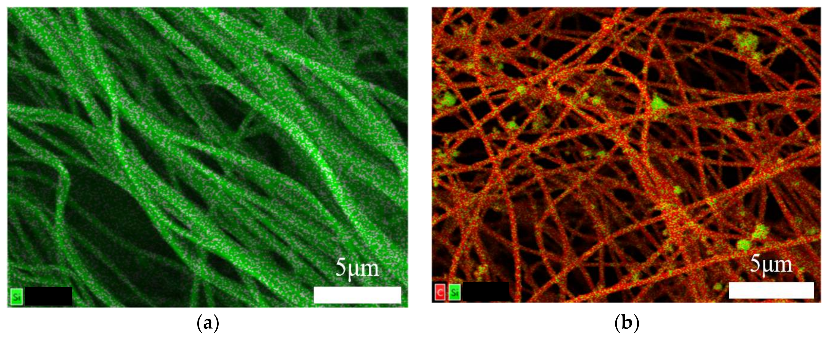
3.1. SEM/EDX Images
Two samples (TEOS Carbon and TEOS/Si Hybrid Carbon) were created, as shown in
Table 1. SEM/EDX images of them are presented in
Figure 1a,b. Both samples exhibited long and continuous cylindrical morphologies with average diameter of 200–300 nm. The distribution of carbon and Si is highlighted in red and green, respectively.
The elemental mapping data of TEOS Carbon (
Figure 1a) indicates Si components are dispersed homogeneously in the carbon nanofibers. This is due to the mixed TEOS. It can be considered that the Si components are amorphous SiO
2 and/or SiOC [
4]. In addition, the elemental mapping data of TEOS/Si Hybrid Carbon (
Figure 1b) indicates Si components and Si nanoparticles are dispersed homogeneously in/on the carbon nanofibers.
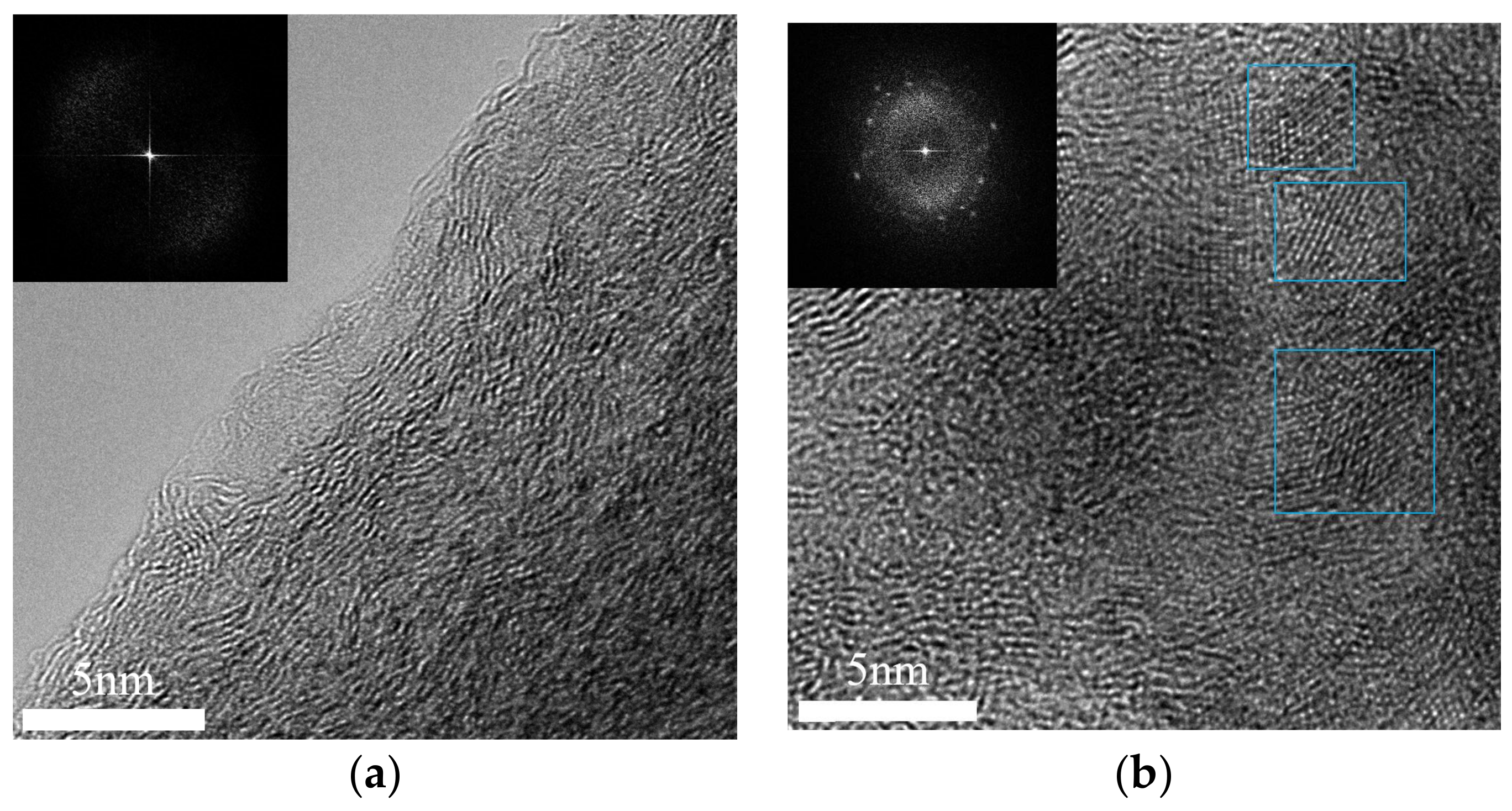
3.2. TEM Images with Image Processing
TEOS Carbon and TEOS/Si Hybrid Carbon were observed by TEM. Fourier transfer was, in addition, carried out and power spectra of the TEM images were obtained. The image processing technique is useful to analyze nanostructures [
5]. TEM images and the corresponding power spectra are shown in
Figure 2a,b.
As a result of observation, it was clarified that TEOS carbon has no Si crystal. The power spectrum of TEOS Carbon shown in
Figure 2a also proves this fact. The result indicates TEOS generates amorphous SiO
2, SiOC and/or SiC. On the other hand, some Si nanoparticles were found in the carbon nanofibers, as shown in
Figure 2b. This can be a solution for falling problem of the Si particles during charging/discharging.
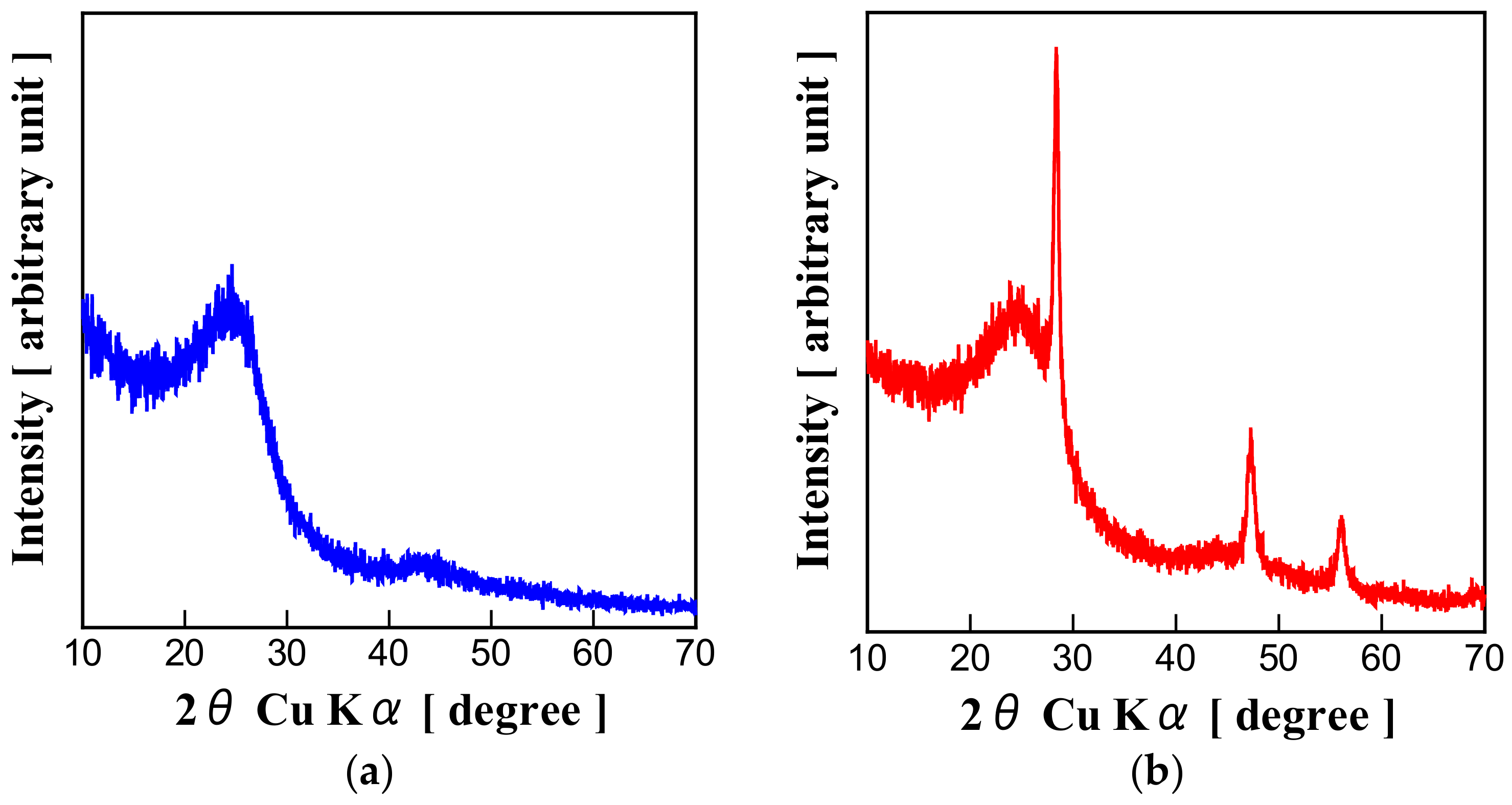
3.3. XRD Patterns
Powder XRD using CuΚα radiation (
λ = 0.15418 nm) was adopted to determine the precise structures of two samples. XRD patterns of them are displayed in
Figure 3a,b. Peculiar peaks of Si can be found from the XRD pattern of TEOS/Si Hybrid Carbon (
Figure 3b), while XRD pattern of TEOS Carbon (
Figure 3a) has no peaks of Si. The result also proves Si components generated from TEOS are amorphous or in atomic state. From the position of the 002 peak 2
θ in XRD, the interplanar spacing
d002 can be determined using the Bragg equation.
d002 of TEOS Carbon and TEOS/Si Hybrid Carbon were calculated to be 0.363 nm and 0.356 nm, respectively.
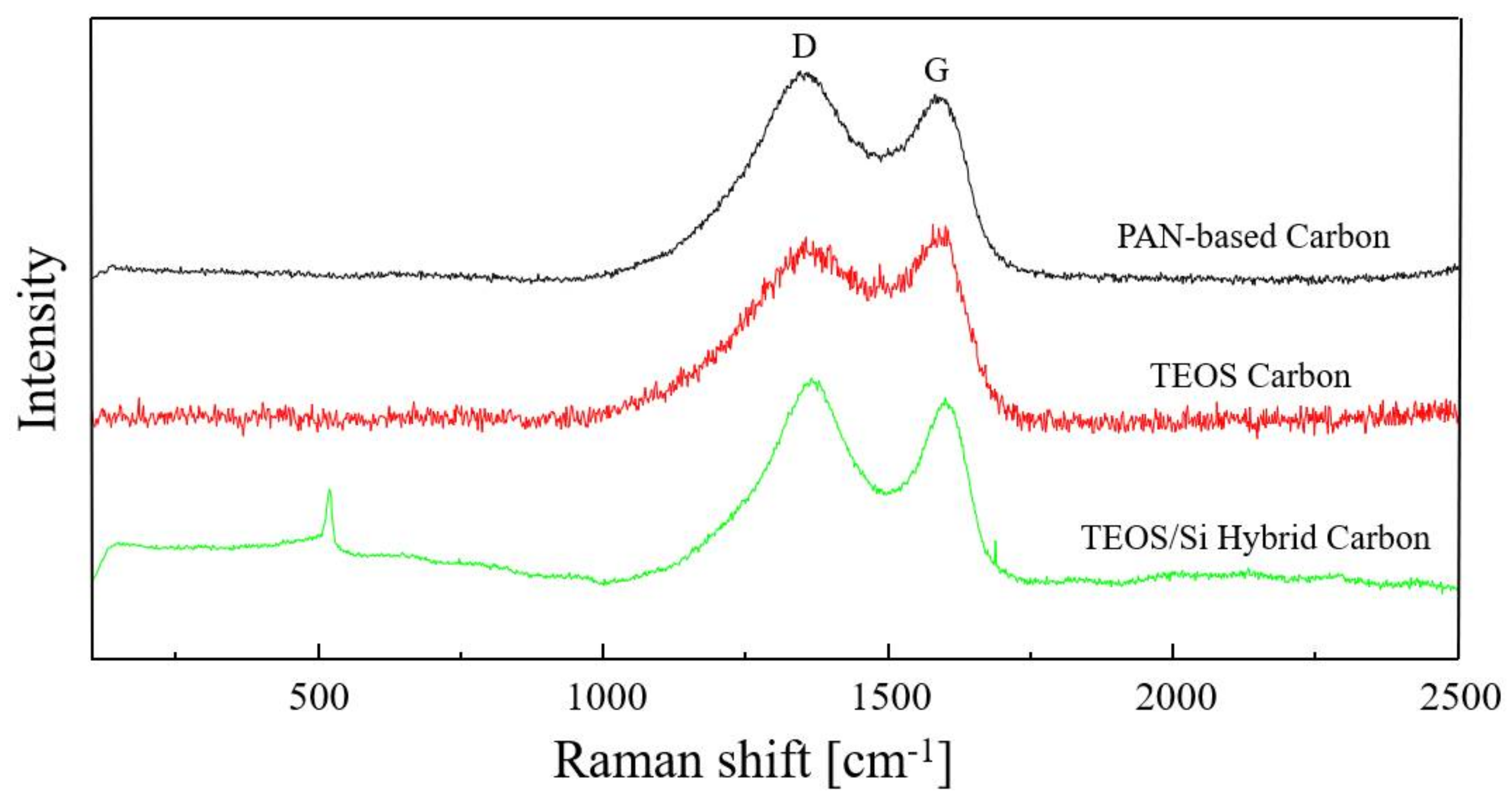
3.4. Raman Spectra
The Raman spectra of PAN-based Carbon, TEOS Carbon and TEOS/Si Hybrid Carbon are shown in
Figure 4. In these Raman spectra, there are two large peaks called D-band and G-band. D-band is from amorphous structures of carbon, and appeared at around 1350 cm
−1. G-band is graphitic structures of carbon, and appeared at around 1590 cm
−1. They are used to obtain R ratio, intensity ratio
ID/
IG. The R ratio of PAN-based Carbon, TEOS Carbon and TEOS/Si Hybrid Carbon are calculated to be 1.01, 0.95 and 1.09, respectively. Additionally, peculiar peak of Si can be found at around 500 cm
−1 in the Raman spectra of TEOS/Si Hybrid Carbon. This result reflects the effect of mixed Si nanoparticles. In the Raman spectra of TEOS Carbon, however, the broad band appears at around 500 cm
−1. It is probable that this is due to a contribution from the amorphous SiOC related structure [
4].
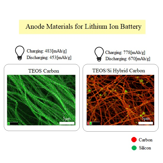
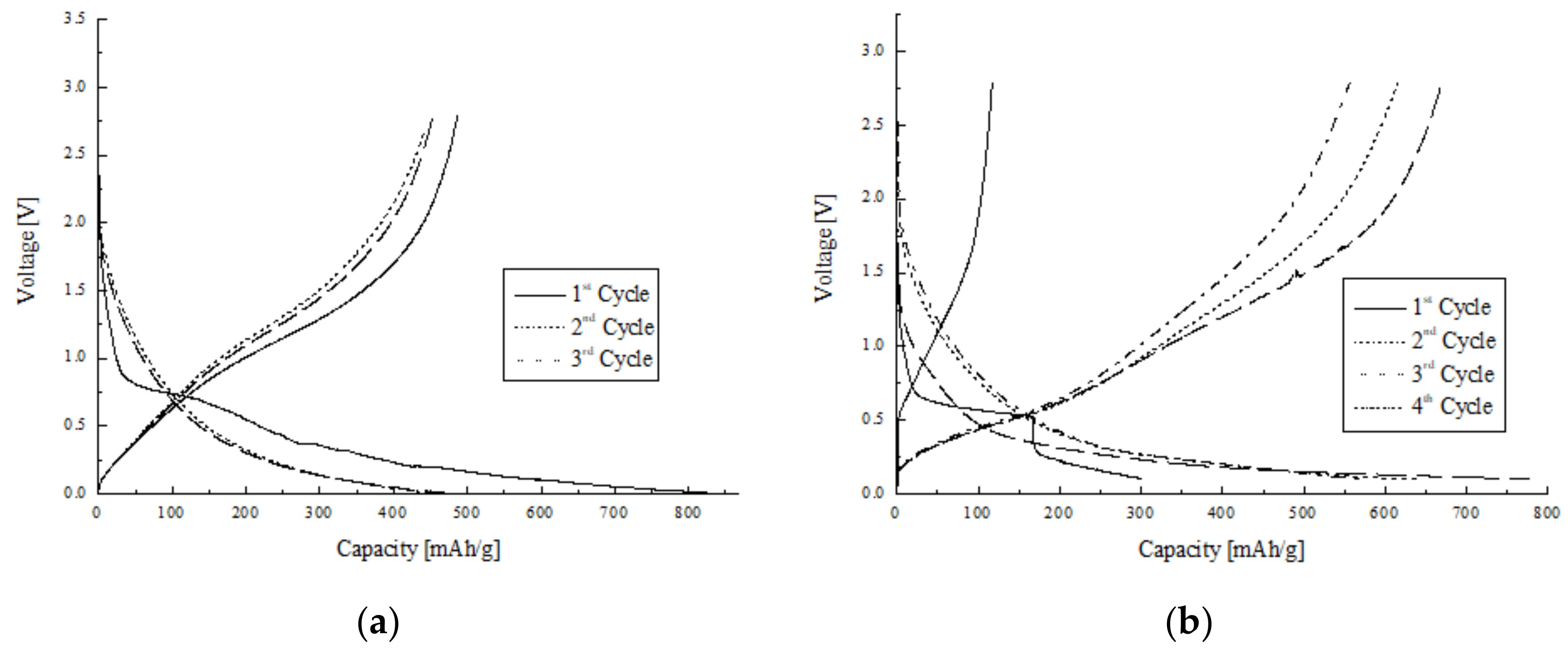
3.5. Electrochemical Characterization
Galvanostatic charging/discharging curves of TEOS Carbon and TEOS/Si Hybrid Carbon are displayed in
Figure 5a,b. Ni mesh-based electrode was adopted for electrochemical experiments of the TEOS Carbon, as shown in
Section 2.3.1. Charging/discharging capacity for the second cycle was 483 mAh/g and 453 mAh/g, respectively. They are higher than the theoretical capacity for graphite. Charging capacity for the first cycle was 842 mAh/g. It is considerably higher than the theoretical capacity for graphite with a relatively large irreversible capacity of 355 mAh/g. Discharging capacity decreases slowly with the progress of cycling.
Cu foil-based electrode was used for electrochemical experiments of the TEOS/Si Hybrid Carbon, as shown in
Section 2.3.2. Charging/discharging capacity for the second cycle was 778 mAh/g and 670 mAh/g, respectively. They are much higher than the theoretical capacity for graphite. It can be found that capacity for the first cycle is very low. This is because electrodes exhibit an activation process which is presumed to result from the gradual wetting process of the electrolyte [
6]. In other words, in the first charging/discharging cycle of TEOS/Si Hybrid carbon, since Li ions did not easily enter Si particles, the capacity was smaller. The Si particles were activated during the first cycle and the capacity increased in the second cycle. In general, Si particles exhibit a well-defined discharging plateau at low voltage. As shown in
Figure 5b, however, the place where the plateau usually appears is inclined. It can be considered that this is due to the mixed TEOS. Both TEOS and Si nanoparticles affected the charging/discharging capacity. In
Figure 5b, there are two inflection points around 200 and 320 mAh/g in the second cycle discharging line. The plateau below 200 mAh/g is due to Si particles and the plateau between 200 and 320 mAh/g is due to TEOS compared to
Figure 5a.
4. Discussion
The present study developed TEOS Carbon and TEOS/Si Hybrid Carbon, electrode materials for the anode of LIB. The cell, consisting of Ni mesh-based electrode made of TEOS Carbon, exhibited a bit higher capacity (charging: 483 mAh/g; discharging: 453 mAh/g, second cycle) than the theoretical capacity for graphite. Discharging capacity of the sample decreased slowly with the progress of cycling. It can be considered that the high capacity was obtained not only because of TEOS, but also because of nanostructures of the carbon nanofibers. It is likely possible that the nanostructures of the carbon nanofibers were changed through carbonization at 1000 °C combined with TEOS. The electrode made of TEOS/Si Hybrid Carbon using Cu foil exhibited a high capacity, almost two times higher than the theoretical capacity for graphite at the second cycle (charging: 778 mAh/g; discharging: 670 mAh/g). This is a substantial achievement of the research. Consequently, TEOS/Si Hybrid Carbon revealed that both TEOS and Si nanoparticles affected the charging/discharging capacity.
The content of Si in TEOS carbon was measured to be about 5 wt % by EDX. The discharging capacity of TEOS/Si hybrid carbon was 50% higher than that of TEOS carbon. If the Si particles were 100% used, the amount of Si particles was about 5 wt % considering that the charging/discharging capacity of Si is 4200 mAh/g. In fact, since Si particles were not 100% activated, the content of Si in the TEOS carbon and TEOS/Si Hybrid carbon was considered to be 10 wt % or more.
From the results of XRD and Raman spectroscopy, it was clarified that the two samples made in this research were hard-carbon-like materials. It is also obvious that 002 peaks of the two samples in XRD patters are broad and their calculated
d002 is wider than that of graphite (TEOS Carbon
d002: 0.363 nm, TEOS/Si Hybrid Carbon
d002: 0.356 nm > Graphite
d002: 0.3354 nm). In addition, R ratio calculated from Raman spectra was not around that of graphite (TEOS Carbon R ratio: 0.95, TEOS/Si Hybrid Carbon R ratio: 1.09, Graphite powder R ratio: 0.19 ± 0.02 [
7]). Since HEV and PHEV require batteries made of hard-carbon, it is highly possible that these two samples might be used for their batteries in the future.
Acknowledgments
This work was partly supported by grant-in-aid (No. 15K06004) of Ministry of Education, Sports, Culture, Science and Technology (MEXT), Japan, and Nanotechnology Platform Program (Molecule and Material Synthesis) of MEXT. Acknowledgments are also made to Analysis and Development System for Advanced Materials (ADAM) and Cooperative Studies Using Collaborative Research Facilities of Wood Composite of Research Institute for Sustainable Humanosphere of Kyoto University. Moreover, this work was partly supported by grant-in-aid of The Foundation for Applied Research and Technological Uniqueness at Nagaoka University of Technology.
Author Contributions
Kyoichi Oshida conceived and designed the experiments; Takunori Minamisawa, Nozomi Kobayashi and Daiki Misawa performed the overall experiments; Akinobu Ando carried out the image processing and analyzed TEM images; Tomoyuki Itaya contributed regents/materials/measurement tools; Minoru Moriyama, Kozo Osawa and Toshimitsu Hata gave technical advice on electrospinning; Yuta Sugiyama and Hiroto Iguchi performed Raman spectroscopy experiments and gave some advices on electrochemical experiments; Naoya Kobayashi contributed materials and gave technical advice on silicon and LIB; and Takunori Minamisawa wrote the paper.
Conflicts of Interest
The authors declare no conflict of interest.
References
- Zhang, W.-J. A Review of the Electrochemical Performance of Alloy Anodes for Lithium-Ion Batteries. J. Power Sources 2011, 196, 13–24. [Google Scholar] [CrossRef]
- Inagaki, M.; Yang, Y.; Kang, F. Carbon Nanofibers Prepared via Electrospinning. Adv. Mater. 2012, 24, 2547–2566. [Google Scholar] [CrossRef] [PubMed]
- Kobayashi, N.; Inden, Y.; Endo, M. Silicon/soft-carbon nanohybrid material with low expansion for high capacity and long cycle life lithium-ion battery. J. Power Sources 2016, 326, 235–241. [Google Scholar] [CrossRef]
- Kim, S.Y.; Kim, B.-H.; Yang, K.S.; Oshida, K. Supercapacitive properties of porous carbon nanofibers via the electrospinning of metal alkoxide-graphene in polyacrylonitrile. Mater. Lett. 2012, 87, 157–161. [Google Scholar] [CrossRef]
- Oshida, K.; Murata, M.; Fujiwara, K.; Itaya, T.; Yanagisawa, T.; Kimura, K.; Nakazawa, T.; Kim, Y.A.; Endo, M.; Kim, B.-H.; et al. Structural analysis of nano structured carbon by transmission electron microscopy and image processing. Appl. Surf. Sci. 2013, 275, 409–412. [Google Scholar] [CrossRef]
- Yin, S.; Ji, Q.; Zuo, X.; Xie, S.; Fang, K.; Xia, Y.; Li, J.; Qiu, B.; Wang, M.; Ban, J.; et al. Silicon lithium-ion battery anode with enhanced performance: Multiple effects of silver nanoparticles. J. Mater. Sci. Technol. 2018. [Google Scholar] [CrossRef]
- Jasim, D.A.; Lozano, N.; Kostarelos, K. Synthesis of few-layered, high-purity graphene oxide sheets from different graphite sources for biology. 2D Mater. 2016, 3, 1–17. [Google Scholar] [CrossRef]
© 2018 by the authors. Licensee MDPI, Basel, Switzerland. This article is an open access article distributed under the terms and conditions of the Creative Commons Attribution (CC BY) license (http://creativecommons.org/licenses/by/4.0/).


