
The Role of Synthetic Fuels for a Carbon Neutral Economy

Institute of Earth Sciences, and Department of Physics, University of Évora, 7000-671 Évora, Portugal
C 2017, 3(2), 11; https://doi.org/10.3390/c3020011
Submission received: 8 December 2016
/
Revised: 13 April 2017
/
Accepted: 13 April 2017
/
Published: 20 April 2017
(This article belongs to the Special Issue Materials and Processes for Carbon Dioxide Capture and Utilisation)
Abstract
:Fossil fuels depletion and increasing environmental impacts arising from their use call for seeking growing supplies from renewable and nuclear primary energy sources. However, it is necessary to simultaneously attend to both the electrical power needs and the specificities of the transport and industrial sector requirements. A major question posed by the shift away from traditional fossil fuels towards renewable energy sources lies in matching the power demand with the daily and seasonal oscillation and the intermittency of these natural energy fluxes. Huge energy storage requirements become necessary or otherwise the decline of the power factor of both the renewable and conventional generation would mean loss of resources. On the other hand, liquid and gaseous fuels, for which there is vast storage and distribution capacity available, appear essential to supply the transport sector for a very long time ahead, besides their domestic and industrial roles. Within this context, the present assessment suggests that proven technologies and sound tested principles are available to develop an integrated energy system, relying on synthetic fuels. These would incorporate carbon capture and utilization in a closed carbon cycle, progressively relying mostly on solar and/or nuclear primary sources, providing both electric power and gaseous/liquid hydrocarbon fuels, having ample storage capacity, and able to timely satisfy all forms of energy demand. The principles and means are already available to develop a carbon-neutral synthetic fuel economy.
1. Introduction
In 1950, 30 percent of the world’s population was urban, but growing fast from 746 million in 1950 to 3.9 billion in 2014, its share being projected to attain 66% by 2050. Within the urban population, in 1990, there were 10 “mega-cities” with ten million inhabitants or more worldwide, which were home to 153 million people, 7% of the global urban population at the time. In 2014, those figures had risen to 28 mega-cities, 453 million people, 12% of the world’s urban dwellers. By 2030, the world is projected to have 41 mega-cities. Presently, more people already live in urban areas than in rural areas (54 versus 46 percent of the world’s population in 2014) [1]. This evolution has been supported by the availability and extension of networks of utilities, in particular energy carriers, which conversely weighs in pressing for further urban development into the foreseeable future. An ever smaller share of population relies on autonomous provision of energy technologies and resources.
Society needs to include easy access to mobility means, lighting, heating and cooling, prime-movers, appliances and instruments, which require energy flows in the form of convenient energy carriers, such as electricity and fuels, also steam and compressed air in an industrial context. These energy carriers are derived from primary stocks or flows of energy: solar radiation and solar derived manifestations—such as biomass, water and air flows, coal and other fossil fuels—as well as nuclear, geothermal or gravity (tidal) sources.
Fossil fuels that presently supply most of the overall energy demand are becoming increasingly inaccessible and environmentally threatening, so that one is considering moving away from depending on them in the long run. One faces two problems: firstly, to replace fossil fuels as primary energy sources, although maintaining as possible the supply of hydrocarbons or other compatible fuels for end-use; secondly, further expand the existing capacity of electrical energy storage, to enable the penetration of electrical generation driven by renewable energy flows and improve the efficiency of their capture, even those that are inherently variable and intermittent.
Relying progressively more on renewable and nuclear energy sources poses the question as to which energy carriers those sources will be converted into. It does not necessarily imply giving up the carbonaceous fuels (and other chemicals) that presently are derived from coal, oil, and gas extractive industries. Those primary sources can be put to work to drive the synthesis of fuels compatible with the present infrastructures and appliances, in particular non-fossil hydrocarbon fuels, produced from environmental CO2 and H2O feedstocks. Such fuels will be environment friendly and fully compatible to displace the fossil-based fuels of today. This concept is translated in the terms “carbon-free” and “carbon-neutral” fuels [2,3]. To be carbon-neutral, the CO2 emitted when burning those fuels would admittedly be recaptured and reused, according to the “carbon capture and utilization” (CCU) principle. Capture may take place at the point source benefitting from higher CO2 concentration, but direct or indirect capture from atmospheric air is also contemplated to account for diffuse sources. The open link in this scheme is the conversion of CO2 and H2O feedstocks into methane or diesel and other fuels and chemicals, through well established catalytic thermochemical processes and currently the object of the petrochemical industries.
Electricity is a carbon-free energy carrier most convenient for many end-uses that is derived from any energy source. The expansion of storage capacity in the electrical grid is a necessity being brought to fruition by the experience gained with the growing share of power generation from intermittent energy sources—including solar photovoltaic, concentrated solar and wind power. Most of the renewable energy sources (RE) cannot provide base load electric power due to their inherent variability and intermittency. To overcome this difficulty, back-up plants and energy storage capacity have to be integrated in the power grid. While RE make up a growing share of the primary energy supply mix for electrical power generation across the developed world, corresponding energy storage capacity has lagged far behind. Storage is required to timely match supply to demand, and its urgency is enhanced by the correlation over large (synoptic) geographic areas of the variability of both solar and wind resources. This causes difficulties in the uptake and transport of renewable energy inputs and in handling the electrical grid stability.
Energy storage is an issue for every energy carrier, and an issue for every energy source. Fossil and nuclear fuels and biomass are stocks or funds that can be extracted when necessary or at a planned rate. However, natural flows like solar radiation or ocean or atmospheric energy are seasonally variable and intermittent. Electrical energy for human purposes is not a primary source but a carrier and incidentally difficult to store. Large scale storage solutions resort to electricity conversion and storage under another energy form; the present day practice relies mostly on mechanic storage, namely as pumped hydro and compressed air. Conversion into chemical energy such as hydrogen or carbon-based chemicals, such as “synthetic or substitute natural gas” (SNG) or ordinary hydrocarbon fuels, are technically viable and would offer the possibility of vast storage capacity [4,5,6].
One understands that the present energy transition relies on energy storage assets that encompass all technical solutions and pervade the whole energy system in assisting production, consumption and grid stability and management, from the very-high through to the low voltage levels, as well as off-grid needs and solutions. The whole system requires stored energy available at top grid level and decentralized at urban, industry/commercial, community and household size plants and devices. Distributed storage in electric vehicle fleets is included in the broad range of the storage solutions.
Assuming excess electric power generation, electrical energy can be converted into hydrogen chemical energy at an efficiency loss of about 20%. The subsequent transformation of hydrogen (together with captured carbon dioxide) into methane carries a similar loss. The reverse conversion from SNG to electricity in a combined cycle gas turbine (CCGT) may attain 60% efficiency, so that for the whole sequence, from primary electricity production to gas storage and back to electricity when needed, a round trip efficiency approaching 40% can be expected [4].
The highly developed natural gas grids across the European Union offer a huge storage capacity, its extent allowing for practically time-independent inputs and outputs in/from storage. Provided the inter-conversion between natural gas and electricity is fluently available, the gas grid is equally well suited for circumventing both storage and transport constraints in the electrical grid, caused by excess or insufficient energy generation or demand in different points of this grid. With the added advantage that transportation of gas is more than tenfold cheaper than transportation of the equivalent amount of electric energy.
The Power-to-Gas (PtG) and Power-to-Liquids (PtL) schemes propose the following: Capturing the excess electrical generation (given the combined overcapacity of renewable and baseload installed capacity) to be converted into gaseous or liquid carbon-neutral fuels and then having these introduced into the storage, transmission, and distribution networks of such fuels. Using these fuels in power plants connected to the gas/liquid grids to assist the electrical grid as back-up, when facing higher electricity demand that cannot be met by already operating plants [7,8,9].
This approach offers two additional opportunities: firstly, it contributes to diminish the demand for fossil fuels and to enforce the useful capture and utilization of carbon dioxide; secondly, it provides an alternative to supply the hydrocarbon fuels and carbon-based chemicals required by the existing transport infra-structure and chemical industries.
Since the turn of this century, not only academic articles, but reports from public authorities, energy operators, and industries, have shown growing awareness and initiative in addressing the PtG and PtL concepts with a view to implementing them [10,11,12,13,14,15]. These sources provide data and analysis that can support independent assessments and additions to these promising schemes.
2. From Storage Capacity to Carbon Neutral Fuels
The world installed wind power capacity has increased since 2000 at 22%/year up to 318 GW in 2013 [16]. Wind power has already attained a high share of the electricity supply in European countries. In Denmark and Spain, wind energy production has become the largest source of electricity; and in Portugal and Ireland has become the second largest. However, wind, as well as solar radiation are fluctuating and intermittent energy flows with inherent variability require to be balanced in order to insure electric grid stability. Handling renewable energy at a very large scale calls for a systemic approach including interconversion among different energy carriers and energy storage solutions. Currently this is not the case, and it is causing difficulties of integrating RE in the existing electrical grid.
Ample storage capacity to assist the electrical grid is a priority. As compared with flywheels, batteries, compressed air, and pumped hydroelectric, chemical fuels offer long-term and large-scale energy storage capacity opportunities. In addition, gaseous and liquid fuels are premium energy carriers themselves. The Power-to-Gas (PtG) process chain was first proposed in the 1980s. The interest in it has been growing in recent years, driven by the increasing share of wind and solar power supply installed in the electric grid. In the meantime, there is a significant amount of PtG research going on in different countries, namely in Japan, France, Germany, Switzerland, and Denmark, where pilot plants are under construction or in operation.
The PtG approach links the power grid to the gas grid by converting surplus electric power into a grid compatible gas, via a two-step process: H2 production from water, followed by H2 conversion to CH4 (methanation) as SNG. The direct injection of H2 into the gas grid is limited by technical standards and regulations. Moreover, storing gaseous or liquid hydrocarbons, rather than hydrogen, takes advantage of their much higher volumetric and mass energy density, and the already available storage, transport and distribution networks.
To exploit the surplus intermittent electricity by converting it into SNG, rather than adopting the current practice of power curtailment or sale at negative price, raises the capacity factor of the RE generators from the presently low levels, providing economic arguments in favor of the PtG scheme. Furthermore, investment otherwise needed to strengthen the grid inter-connections to handle peak intermittent power is thus avoided.
Plants realizing PtG will extract excess generation in response to imbalance in varying levels of generation or demand, providing fast ramping up and down for dynamic stabilization of the grid. Plants in charge of the reverse Gas-to-Electricity (GtP) conversion will provide response as back-up generation, requiring around 15 min to ramp up in the case of the gas turbine, however much faster in the case of gas or diesel engines and of fuel-cells.
In case of over-generation of gas, this can be made available to replace fossil natural gas (NG) rather than being re-converted back into electricity, with economic advantage, given that (besides avoiding the energy penalty inherent in the conversion back into electricity) the same amount of imported gas would be spared or displaced.
Methane is widely used for domestic and industrial heating and there is no real alternative to liquid hydrocarbons in most segments of the transportation sector. Past over a century-long learning curve, current prime movers are designed for hydrocarbon fuels. Aircraft rely on highly concentrated energy storage on board to enable long haul flights. Busy shipping lanes provide the mainstay for most of the international trade. Instead of discarding the energy carriers one might just replace the primary energy sources.
PtG technology solutions do not question the energy carriers that provide good performance, but rather open opportunities to change the primary energy source from which they are derived. Namely solar and nuclear energy, of which there are ample resources, can become the sources that provide hydrocarbon and other petrochemicals, SNG and liquid synthetic fuels in particular. The SNG can be injected into the existing gas grid, to be used as CNG motor fuel or burnt in natural gas consuming industrial facilities. The total world storage capacity of natural gas exceeds 3800 TWh—to be compared to the annual world total electrical power production from wind and solar sources, nearly 1100 TWh in 2015 [16,17].
An alternative to SNG is the production of liquid fuels. The functionality of PtG can indeed be extended, leading the syngas through the Fischer-Tropsch synthesis (FTS) into liquid fuels, including diesel, methanol, dimethyl-ether, and other fuels and chemical feedstocks, displacing the import of crude oil and refinery based distillates and petrochemical products [18]. This is the Power-to-Liquid (PtL) scheme.
The proposed PtG and PtL schemes are prime opportunity to implement carbon capture and utilization, by opting for carbon-neutral synthetic fuels as media of energy storage and use, that is, synthetic fuels that offer an effective alternative to using carbon-free fuels, as proposed by the “Hydrogen economy” concept. Carbon-neutral hydrocarbons are obtained by capturing and converting CO2 into fuel by combining it with H2 and can be regarded as an on-going form of carbon temporary storage [19]. Hydrogen can be produced in a dedicated plant in long tested processes and as a fuel is inexpensive, regarding the energy equivalent amount of crude distillates. The barrier to the use of hydrogen itself as a fuel outside the chemical industry resides in transmission and distribution constraints and vehicle and appliances designs, rather than its cost. As to large scale CO2 capture, a number of technical solutions are maturing and others appear promising. The whole synthetic pathway relies on the availability of a carbon-free primary energy source to supply the hydrogen and drive the carbon capture, and to drive the chemical synthesis. Once the two feedstocks are made available, their incorporation into a hydrocarbon fuel is technically feasible and economically attractive. Carbon-neutral hydrocarbon fuels do without the development of new transport and distribution infrastructure and end-use appliances.
The concept of CO2-recycled synthetic hydrocarbon fuels is not new. It emerged in the 1970s, likely stimulated by the oil crises. Steinberg first envisioned the closed-loop CO2-recycled synthetic fuels, including CO2 captured from the atmosphere [20]. In a series of articles and patents, he explored various options to capture CO2 using hydroxide or carbonate absorbents, to produce H2 by water electrolysis, and to synthesize methanol from those two compounds in a process driven by nuclear electricity and heat. He also considered stripping CO2 from sea water as well as from industrial plants flue gases: fossil fueled power and chemical plants (lime, cement, ammonia, etc.), metallurgical and blast furnace operations, natural gas and geothermal wells, and limestone calcination. These ideas might well indeed be brought to fruition.
3. Energy Technologies
3.1. Energy Storage Technologies and Services to the Grid
Energy can be stored in different forms, not necessarily the same as its final use. Electrical energy is actually stored in different forms and devices that are briefly recollected here. Electrical energy storage devices such as supercapacitors, flywheels, and batteries, are excellent in providing high power very fast, but are limited regarding total energy and discharge duration [21,22]. These technologies are accordingly dedicated to offer fast response and/or compensation for short-term fluctuations, and the last two are also of utility for small-scale uninterruptible power supply (UPS).
The ongoing trend in RE participation in the grid is demanding ever more flexibility from the energy systems. Among options for increasing flexibility, given the variability and intermittency of renewable sources, energy storage is the most pressing one. The many existing and developing storage technologies need be scrutinized and their future roles assessed. Different solutions need to be deployed to different locations and for different purposes. However, although any reversible conversion and storage of electricity into any other form of energy is possible, in view of fundamental principles and past experience each option has its own advantages and shortcomings.
Energy services required by the grid range from high power for a shorter duration, to large energy amounts over longer time spans. They can be basically addressed in two broad categories, termed power quality and energy management. The former refers to charge/discharge cycles on the shorter timescale (seconds or minutes), and includes sag compensation and power smoothing, frequency and voltage regulation, grid stabilization, and spinning and standing reserve. The latter refers to charge/discharge cycles on the longer timescale (minutes to hours and longer), and includes load levelling, load following and power balancing, peak shaving and time shifting, and long-term bulk storage [6]. Figure 1 depicts the architecture of a large electric grid, including successive voltage level and transport and distribution power sub-grids, interconnected by transformer stations.
There are various technical possibilities for large scale storage of energy to be delivered as electricity on demand [23,24]. Direct storage of electrical energy can be realized in electric or magnetic form in devices such as supercapacitors and superconducting magnetic energy storage. Pumped hydro-electric (PHS) or compressed air reservoirs (CAES) hold electric energy converted as mechanical energy. Flywheel units buffer electricity as mechanical kinetic energy. Electro-chemical batteries convert electricity and store it reversibly in electrochemical form. Finally, electrical energy can be converted into chemical energy through redox systems in such chemicals as hydrogen, or as SNG, methanol or ordinary hydrocarbon.
A representative selection of tested and performing technical solutions that provide energy storage services to the electric grid is presented in the following sub-sections and summarized in Table 1.
3.1.1. Pumped Hydro Storage
Pumped hydro-electric storage (PHS) is a method of storing electrical energy in mechanical form by moving water between reservoirs at different elevations. At times of low electricity demand, excess generation is used to pump water upstream, while releasing water back downstream when there is higher demand, by means of reversible turbine/generator assemblies. Pure pumped storage plants just shift the water between reservoirs, but pump-storage plants can also generate electricity as run-of-the-river hydroelectric plants do. Taking into account turbine/generation-group losses and evaporation losses from the free water surface, round trip energy efficiency can attain 80% [22,23]. This method is the best proven and most cost-effective means of storing large amounts of electric energy on an operating basis; but high capital cost and appropriate geography and environmental context are critical factors.
Hydro-pumped storage is by far the most exploited solution of the total 128 GW worldwide installed storage capacity. Hydro-pumped plants cannot respond to fast power demand, rather they are best suited for high-power long-time services, namely energy management. They operate efficiently at high capacity and for large energy loads, above 20 MW and 50 MWh; top power reaches 3 GW (Bath County Pumped Storage Station, Warm Springs, VA, USA). Alqueva dam (Portugal) is a large reservoir with inter-annual regulation capacity from which water may be distributed to satisfy multiple needs. Commissioned in 2004 and upgraded in 2014, home to four reversible Francis turbines totaling 520 MW capacity.
3.1.2. Compressed Air Storage
In compressed air energy storage systems (CAES), off-peak power is taken from the grid to pump air into sealed geological reservoirs up to high pressure. Various geologic formation types are of potential interest to this effect, namely sealed fossil aquifers, mined salt caverns, and constructed rock caverns. Aquifer storage is by far the least expensive method and accordingly used in most of the present locations of CAES.
CAES comprises as aboveground components: air compressor and turbine, coolers and recuperators, motor/generator group, clutches to provide alternate engagement between modes, and control center. Typical capacities for CAES systems are in the range 50–300 MW, and indeed CAES systems only make sense on a very large scale. The storage period is the longest, due to the fact that there are virtually no storage losses. Fast start-up is also an advantage, a CAES plant can provide a start-up time of down to 3 min (while a conventional combustion turbine typically requires 20 min for a normal start-up) [24].
Huntorf, Germany, started in 1978 rated 290 MW and 900 MWh, exploits two caverns pressurized up to 66 bar. German R&D activities in this field include the deployment of project ADELE, a 200 MW demonstration plant to be brought on line this year, aiming at improving on present day performance by incorporating adiabatic operation (A-CAES), compression heat being retained to be reused in the expansion phase, thereby improving round-trip efficiency.
3.1.3. Thermal Storage
For storing electrical energy, high temperature thermal electric energy storage (TES) can be used (around 500 °C). During the charging phase, heat is generated by an electrical heater or an electricity-driven heat pump can be used instead. In the discharging phase, heat is extracted from the thermal storage to produce steam and drive a turbine-generator to feed power to the grid. TES are medium-term energy storage systems which operate in similar ranges as pumped hydro and compressed air systems. They are currently under advanced research; being composed of more or less standard components, and could be developed in up to 10 years. Thermal storage can work as a power sink for power shaving in case of oversupply in the grid, and to achieve time shifting. The large energy capacity and slow response make it suitable for energy management [24].
Thermal storage is currently mostly associated to “concentrated solar power” (CSP) plants where very high temperatures can be attained, and heat might be conveniently stored as sensible or latent heat, for enabling either thermal energy recovery or conversion to electrical power at any time, day or night. Reference storage media are magnesium oxide bricks and molten salt hydrates.
3.1.4. Electrochemical Battery
Electrochemical energy appears the most obvious solution for electrical energy storage, to assist the electrical grid.
Among the large diversity of battery technologies, a few show potential to assist in the regulation of the electrical power grid. The most obvious option is the Li-ion battery that covers a broad range of applications. Of the best known and most promising, the sodium sulfur (NaS) battery contains molten sulfur at the positive electrode and molten sodium at the negative electrode as active materials, separated by a solid beta-alumina ceramic electrolyte. The electrolyte allows only the sodium ions to go through and combine with the sulfur to form sodium polysulfides. When running, the heat produced in charging and discharging cycles is enough to maintain the operating temperatures at 300–350 °C, no external heat source being required. NaS batteries are built from inexpensive and non-toxic materials and display excellent round-trip energy efficiency (≈80%) [22,23]. The high operating temperature and the corrosive nature of sodium make them suitable for large-scale stationary applications only. They are already currently used in electric grid applications, namely in peak shaving and improving power quality.
3.1.5. Electrochemical Flow Battery
Among electrochemical storage technologies, use of redox flow batteries (RFB) is one of the most recent and a highly promising option for stationary energy storage due to its unique characteristics. They are electrochemical conversion devices which exploit redox processes between two solutions of the same polyvalent species, stored in external tanks and brought to react in an electrochemical converter. This is a membrane electrode assembly (MEA), a sandwich consisting of two catalyzed electrodes with an interposed polymeric membrane, in analogy to the assembly in PEM (polymer- electrolyte or proton-exchange membrane) fuel cell, fed from external storing tanks. The most relevant features of this technology are: flexibility that includes independent sizing of power capacity (converter) and energy stored (tanks), high round-trip efficiency, fast responsiveness (seconds), long durability, scalability, and reduced environmental impact [23,25].
Of the various RFB metal-ion combinations, the most researched and successful technology is the VRB, the only that has reached effective commercialization so far. It uses vanadium dissolved in strong sulfuric acid (5 M); vanadium IV–V (tetravalent–pentavalent) is used on one side whereas vanadium II–III (bivalent–trivalent) on the other, exploiting the ability of this element to exist in solution in four different oxidation states. By using the same metal species in both electrolytes, the electrodes and membrane are not cross-contaminated, allowing for a long lifespan. Electrochemical half-reactions of a VRB are as follows:
Positive electrode: VO2+ + H2O ⇌ VO2+ + 2H+ + e−
Negative electrode: V3+ + e− ⇌ V2+
The hydrogen ions move through the membrane to maintain the electrical neutrality of the electrolytes. VRB provides power density barely reaching 0.1 W/cm2 and the stored energy density does not exceed 35 kWh/m3 [26]. Low power density and energy density make present day RFB unsuitable for mobile uses, but of much interest for stationary applications. The largest plants in operation were commissioned after 2001 in Japan, displaying a few MW in power capacity and a few MWh in stored energy. Operating systems are demonstrating long working life (up to 270,000 charge/discharge cycles) [25].
3.1.6. Electrochemical Cells with Chemical Fuel Storage
For strict electricity storage for support service to the electric grid, plain water electrolysis with hydrogen storage has been considered [27,28]. A typical hydrogen storage system consists of an electrolyzer, a hydrogen storage tank, and a fuel cell. The electrolyzer splits water into hydrogen and oxygen which are stored under pressure in tanks. To regenerate electricity, both gases are pumped back into the reversible electrolyzer or a fuel cell where water is electrocatalytically synthesized, heat being released and electricity regenerated. For economic reasons the oxygen is vented and taken from the atmosphere when power is generated. Smaller amounts of hydrogen are stored in tanks under pressures up to 900 bar, larger amounts in geological reservoirs, namely salt caverns. Instead of fuel cells for power regeneration, a gas motor or turbine can be employed. For larger capacity in the hundreds of MWs, a CCGT can be used for reserve generation. The round-trip efficiency is around 40%. Hydrogen systems can also be managed for decentralized “combined heat and power” (CHP) generation or for decentralized fuel supply.
3.1.7. Power-to-Gas
The Power-to-Gas scheme relies on the conversion of energy from the electric grid into hydrogen or SNG to be stored in the NG system to become available and converted back to electricity in stand-by plants and other plants that provide services to the grid. From the point of view of electrical energy storage, it is anticipated that the Power-to-Gas scheme performing with a deployment time of 10 min, at 35% energy round trip efficiency, might require up to 2000 €/kW investment [7,8,23]. But carbon-free RE generated electricity, that would otherwise be curtailed or sold at a negative price, would produce SNG with about 60% efficiency [4,9] and further displace fossil sourced NG. If returned to the electric grid, the round trip efficiency would be 35% [4,23].
3.2. Energy Conversion
Energy assumes different forms with various qualities. Mechanical and electrical energy both are or can be fully converted into pure work, are plain energy. Thermal and chemical energy might be farther or closer to equilibrium with the environment reference state, therefore able to perform more or less work. Mechanical and electrical energy can be regarded as fully interconvertible and equivalent to work. Thermal energy can be converted into work within Carnot’s limiting relationship. Chemical energy of a given amount of mass depends on elemental composition and chemical bonding, and concentration of the constitutive compounds.
The energy carriers most widely used are electricity, heat, and fuels, although hydraulic fluids, steam and compressed air are also common in certain contexts. Energy carriers can both transmit and store energy, but they do not perform equally in these respects, and accomplish different effects at end use, so that energy conversion concepts and devices are required.
Energy conversion, from one to another energy form, covers all possible combinations. Heat pumps driven by electricity or fuel generate heat flows to higher and from lower temperature levels (in reference to the environment or a particular heat source). Thermoelectric converters generate an electric current between two heat sources at distinct temperature levels. Thermochemical cycles, specifically chemical looping, convert thermal energy flows from/to different heat sources to realize chemical work, particularly fuel combustion or molecular dissociation and species separation etc.
Among energy conversion concepts and devices, electrolysis and electrolyzers are of relevant interest to the present purpose, because they realize the interconversion between electrical and chemical energy forms and because electrolysis assists chemical processes leading to synthesizing fuels; and because electrolyzers, being reversed in fuel cells, assist in burning fuels.
3.2.1. Electrolyzers and Fuel-Cells
Electrolysis appears to be a very promising way of converting electricity into chemical fuels. Electrolysis has been known for two centuries and electrolyzers have already travelled in space exploration. Virtually all electrolyzer cells (EC) are reversible and might work as fuel cells (FC), burning chemicals to deliver electricity. There are a number of cell types worth reporting.
Several types of cells are being investigated or developed, and some are commercially available [27,28,29]. Reviews of electrolysis technology have been carried out, counting on choices of electrode, electrolyte, membrane/separator, charge carrier, operation temperature, efficiency, geometry, etc. The cell types are usually categorized according to the electrolyte.
The electrochemical cell technologies that have taken to the stage and found increasing opportunities in important and some unique applications are: Alkaline electrolytic cell (AEC), proton exchange membrane (PEM), phosphoric acid cell (PAC), molten carbonate cell (MCC), and solid oxide cell (SOC).
Table 2 summarizes technical performance data of best known electrochemical cells, as well as services they can provide to the electric grid and other applications.
AEC/AFC
The classical alkaline electrolyzer cell AEC works at around 100 °C. These are the only type available in case large-scale facilities were to be deployed in the short term and are presently being used in the production of very pure hydrogen. The problem with the alkaline electrolyzer for energy storage is low production rate per cell unit-area or low efficiency (or a trade-off between the two).
AFCs operate well at room temperature, have cold start capability and can provide high power densities. However, the alkali hydroxide aqueous electrolyte does not tolerate CO2 due to potential carbonate precipitation. Nevertheless, this is a rather cheap technology and multiple commercial opportunities remain open. Key engineering components and materials are: static or flowing aqueous solution of sodium or potassium hydroxide as electrolyte; anion exchange polymer membrane as cell separator.
In the variant alkaline anion exchange membrane fuel cell, the earlier porous matrix saturated in aqueous alkaline hydroxide is replaced by a solid polymer electrolyte membrane that conducts OH− ions. This option overcomes the problems of electrolyte leakage and CO2 intolerance, though still benefiting from operation of the cell in an alkaline environment favorable to anode fuel oxidation.
PEMEC/PEMFC
Low-temperature PEM is commercialized but due to expensive scarce materials in the electrodes and stack plates they do not appear to be viable for present day electric grid conversion and storage purposes. At high-temperature, the potential for performance and costs is significantly better, in particular if the operation can be raised above 200 °C, when the reaction rates become much faster.
Low temperature PEMFC are considered for automotive applications, back-up power units, micro Combined Heat and Power (CHP) and small portable power supply units. Large stationary PEMFC are also being considered when large H2 streams are available in chemical industry plants. Key engineering issues are: polymeric electrolytes for improved proton mobility; and membrane-conductivity sensitivity to humidity.
SOEC/SOFC
The high temperature (600–1000 °C) solid oxide electrolyzer cell (SOEC) is being widely researched and demonstrated in cell stacks in the kW size range. This cell is fully reversible, the very same cell can also be used as a solid oxide fuel cell. At higher temperature less electrical energy is needed to drive an endothermic reaction, such as water splitting. Co-electrolysis of H2O and CO2 into H2 and CO has been reported practical using SOEC at high temperature.
SOFCs were initially developed for operating at temperature above 900 °C. They rely on dense ceramic non-porous oxide electrolyte and porous ceramic and metal ceramic electrodes, piled in a multi-layered all-solid-state system. Key materials for SOFC are: Ni-cermet fuel electrode, yttria or scandia stabilized zirconia (YSZ) ceramic as electrolyte, and perovskites as air electrode materials. Bipolar plates interconnect the cells in the stack and control the gas flows to the electrodes.
SOFCs, operated at very high temperature, display excellent power output and stability behavior during long-term testing, and can reach 60% power-generating efficiency. SOFC technology is particularly considered for CHP micro-generation, for large high power applications such as industrial generating, and decentralized units for which operation times above 40,000 h are required. The electric efficiency of a SOFC can be further increased by fully extracting the thermodynamic potential of the cell exhaust coupling a gas turbine.
PAEC/PAFC
Phosphoric acid fuel cells (PAFC) have liquid phosphoric acid as electrolyte supported in a silicon carbide matrix and porous carbon electrodes containing a platinum catalyst. Phosphoric acid fuel cells are commercially available. Operating temperature ranges from 150 to 220 °C. This type of fuel-cell is designed for stationary power generation, however, PAFCs have also been used to power large road vehicles. Current issues in their development are membrane lifetime, cold-start properties, and power density.
MCEC/MCFC
Molten carbonate fuel cells (MCFC) operate at very high temperature, above 600 °C. No precious metals need be used as catalysts at the anode and cathode, reducing cost, although the high temperature and the corrosive electrolyte accelerate corrosion and eventual breakdown, so that durability might be a disadvantage. Nevertheless, significant lifetimes from 20,000 to 30,000 h have already been attained, and further progress is still expected, by improving reliability and solving material issues regarding the electrodes, loss of electrolyte and corrosion at bipolar plates. The main efforts in MCFC development have been directed at improved stack and system design and at test and demonstration in the 50–1000 kW range.
The MCFC can be fed by H2, CH4, syngas or reformate at the anode half-cell, while CO2 and O2 need to be fed at the cathode half-cell; H2O and CO2 are released at the anode exhaust. The carbon dioxide is necessary at the cathode to provide the charge carrier, the carbonate ion CO32−, that is transported across the electrolyte and released at the anode at the same rate. If no fresh carbon is incorporated in the cathode feed, the CO2 carried through the electrolyte needs to be recycled back, in a closed-loop to keep the cell going.
Alternatively, if all the CO2 in the anode exhaust stream is diverted, an external CO2 stream input needs to be maintained at the cathode to keep going. This offers an interesting opportunity to use the MCFC to selectively capture CO2 from the flue gas mix of a combustion-based power or industrial plant.
Given that high-temperature heat is produced by the electrochemical fuel “combustion”, the overall energy efficiency can amount to 90% [26], of which up to half is as electric power. MCFCs are therefore suited as steady medium-size CHP co-generators, in hundreds to thousands of kilowatt decentralized plants, and as reliable off-grid power sources.
3.2.2. Co-Electrolysis
Carbon dioxide can be reduced to monoxide by direct electrochemical conversion, in different contexts and for different purposes, including the synthesis of methane and other fuels [26].
Some of the electrolyzers can split both CO2 (into CO and O2) and H2O (into H2 and O2), and the two simultaneously. When the objective is to obtain synthesis gas this finding is of much interest. There are significant advantages in electrolyzing H2O steam and CO2 simultaneously, aimed at investment reduction and seeking electrical efficiency. Electrochemical reduction of CO2 and H2O at room temperature and at high temperature with syngas formation has been demonstrated by several authors [30,31,32]. Current density, yield, and energy efficiency are due to increase; improved electro-catalysts and higher temperature will bring about this performance.
For a SOEC, pure CO2 electrolysis exhibits higher area specific resistance than steam electrolysis, due to the slower overall kinetics of CO2 electrolysis and the higher over-potentials required. For H2O–CO2 mixtures the cell performance is only slightly lower than for H2O alone, but much better than for pure CO2 electrolysis. In co-electrolysis, the RWGS dominates the CO production and the overall electrical requirement becomes lower. Recent developments and performance improvements have demonstrated efficient co-electrolysis of H2O and CO2 in SOEC. In the light of such developments, an overall conversion efficiency of 70% may be expected [19]. This efficiency refers to the heating value of the final product as a fraction of the power input to the process.
The Danish initiative CASE (Catalysis for Sustainable Energy) is working on this. Risø DTU is carrying out activity on CO2 reduction in the temperature and pressure ranges 200–300 °C, 20–50 bar, using both an aqueous carbonate electrolyzer cell and a proton conductor electrolyzer cell [28].
A recent study on electrolysis of CO2 into CO using a LiCO3 molten carbonate electrolyzer at 900 °C and 100 mA/cm2 reported to have attained near to 100% faradaic efficiency and thermodynamic efficiency above 85% [28]. Further advantages are operating the electrolyzer continuously, producing pure CO rather than a mixture of CO and CO2, not requiring scarce metals and no hazardous or toxic by-products being emitted. This would be an alternative to activate the CO2 carbon into the synthetic fuel path in parallel to H2O steam electrolysis—as an alternative to the co-electrolysis path. Further work is needed awaiting confirmation of the full potential of this technology.
3.3. Chemical Energy Storage
Electrical energy storage systems, of long durability and high energy capacity, seek to shift the time of electric power generation to that of consumption, and are expected to play a major role in future electric grids in view of the planned growth of the share of inherently variable RE generation. No technology commercially available right now complies entirely with all the specifications for such an efficient and reliable storage system. However. electrolyzer cells (EC) are reversible and might work as fuel cells (FC) as well. This dual role, in the same device (or in a pair working on opposite senses) offers an opportunity of storing electrical energy as chemical energy [6]. The proposed storage media are light hydrocarbons and other organic species for which synthesis CO2 and H2O streams are the required feedstocks. Among electrochemical cells a few are proving to be reversible, reliable, efficient, and scalable. These will likely integrate the PtG scheme.
There are three main electrochemical technologies—AEC (Alkaline Electrolytic Cell), PEM (Proton Exchange Membrane) and SOC (Solid Oxide Cell)—that appear at the forefront. The first one is a mature technology, well known and used in industry. The second one, more recent, is used in small facilities. The last one is still at the pilot stage; operating at high temperature, displays improved energy efficiency in converting electrical to chemical energy by also partly consuming thermal energy. If the option is to reach methanation by the way of CO2/H2O co-electrolysis, then PEM, SOC or MCC (Molten Carbonate Cell), at high temperature and current density appear as the most promising. The issuing syngas can readily be converted into SNG in a reactor where methanation takes place at high pressure and low temperature on a Ni-based catalyst.
The solid oxygen electrochemical cell (SOC), working as EC or as FC, appears a first choice for the time being. Such a device, working as an electrolyzer cell, is able to electrically drive the dissociation of a H2O–CO2 mix to give rise to SNG on the anode half-cell side, to be stored as reserve for later reverse fuel-cell mode generation of electricity. A stand-alone system based on this technology, coupling the two operating modes with interim storage of both reactants and reaction products, was modeled and optimized to show that the round-trip efficiency might reach 79% [33].
The reversible SOC offers a promising approach to energy storage; it can either convert a feedstock into a chemical fuel (electrolyzer mode) to store electricity, or convert a stored fuel to deliver electricity (fuel-cell mode). Its widespread use has been hindered and delayed by insufficient long-term stability, particularly at high current densities. However, it has recently been shown that performance degradation need not be irreversible, and might even be eliminated by cycling the cell between electrolyzer and fuel-cell modes, in analogy to the common handling of rechargeable batteries [34].
A large body of research and demonstration converges in suggesting the viability of employing SOC in electricity storage. Meanwhile, several improvements should be achieved. A new SOC concept, taking advantage of the high temperature heat released while in the fuel-cell mode, consists in storing that heat flow as sensible or latent heat, to be returned back to the cell when working in the electrolyzer mode [35]. The roundtrip efficiency when optimized should not be far from 70%.
The electrolyzer is a central component of Power-to-Gas scheme, as it converts electrical energy into chemical energy of SNG that can be introduced into the gas grid. As to the feasibility of the PtG scheme, the energy performance currently available is characterized by conversion efficiencies from electricity to synthetic gas at around 70% HHV for hydrogen and 55% HHV for methane [9]. In the midterm, the performances could be significantly increased to yield up to 85% for electrolytic hydrogen and up to 70% for methane, by means of proper heat management in coupling the high temperature electrolyzer to the methanation reactor.
4. Carbon Dioxide as a Feedstock
The objectives of either CCS (Carbon Capture and Storage) or CCU (Carbon Capture and Use) concepts require the acquirement of concentrated streams of CO2 transportable at distance. Three main methods of obtaining this stream are currently available: Scrubbing flue gases and other industrial emissions; capturing CO2 from thin air or seawater. In the present work another one is also consideration of extracting carbon from carbon-rich geo-materials, such as carbonate rock.
4.1. Carbon Capture and Separation
Separation of CO2 from a flue gas or another dilute source like the atmosphere involves two main stages: the capture (onto a fluid or solid support or carrier) and regeneration (of the fresh carrier) when pure CO2 is separated or released.
The use of alkaline absorbent solutions has dominated the work carried out in scrubbing gaseous flows to capture CO2 and obtain concentrated CO2 streams. Metal hydroxides in general readily react with CO2 to form carbonates, to be later released and regenerate de absorber, in a thermochemical cycle. Hydroxide solutions, mostly sodium and potassium hydroxides, have been used to that effect in a number of industrial applications.
The process more generally adopted in CO2 scrubbing is a thermochemical absorption cycle that consists of a succession of four reactions that in turn form two coupled sub-cycles [36]. Those four steps are: absorption, “causticization”, regeneration, and hydration. The CO2 is absorbed by sodium hydroxide (NaOH) giving rise to a sodium carbonate solution. In the causticization step, calcium hydroxide (hydrated lime, Ca(HO)2) is added to the sodium carbonate solution leading to the precipitation of insoluble calcium carbonate (CaCO3). The sodium hydroxide is thus regenerated to be recycled. The CO2 is then released by calcination that is the thermal decomposition of the calcium carbonate in a kiln, while the quick-lime (CaO) left is hydrated to be recycled too.
The absorption reaction is an established engineering technology, and the remaining reactions are familiar to the pulp and paper industry; they can be readily adopted for CO2 air capture, with adaptations. Energy requirements are dominated by the decomposition of calcium carbonate, which requires high-temperature heat that nevertheless has the potential of being partly recovered at lower temperature via steam hydration of the quick-lime (slacking), thereby significantly improving the energy efficiency of the overall process. While technically feasible, for the present purpose the amount and form of energy consumed is relevant in terms of CO2 emissions, given the fact that the energy demand per unit mass of CO2 captured is larger than the heat released when emitting the same amount of CO2 by the combustion of coal, although smaller than of methane. Accordingly, non-fossil fuel energy (nuclear, solar or other renewable) should in principle be used to drive this CO2 capture process.
Adsorption, the physical molecular binding of an adsorbate onto a solid surface, involves smaller energy jumps than absorption into a fluid, and the cycle adsorption-desorption can be driven by both thermal and pressure swings, the latter significantly reducing the energy demand, such that adsorption appears to offer a promising alternative over the absorption option [37,38]. Porous materials having large specific surface areas (m2/m3), such as zeolites, activated carbon, engineered CNTs (carbon-nanotubes), and MOFs (metal–organic frameworks) are the media of choice, and are being explored regarding CO2 capture. However, a recent review that examined different routes to capture CO2 from flue gases realizes the difficulties posed by the so far insufficient selectivity of the tested materials towards CO2 in those gas mixtures. Nevertheless, other paths remain open to research aiming at effective and energy efficient CO2 capture and separation technologies, namely membrane and cryogenic [38].
Alkaline caustic solutions are amenable to atmospheric or to flue gas CO2 capture. The CO2 captured in the hydroxide aqueous solutions is converted into aqueous bicarbonate and/or carbonate anions, thereafter recoverable by thermochemical means. Alternatively, the release of the CO2 can be achieved by electrochemical means [5,39]. The solution is fed into a Bipolar Membrane Electro-dialysis unit, set up by applying a voltage across a stack of alternate pairs of ion-selective anion-exchange membranes (AEM) and water-dissociating bipolar membranes (BPM). The anions are transferred from the basic to the acidic side of each AEM, along the electrochemical stack, driven by the applied electric field. In the acidic medium the HCO3− ion is converted into CO2, and its low solubility in the acidic solution eventually results in CO2 gas evolution and caustic solution regeneration. This CO2 electro-dialysis regeneration from bicarbonate solutions requires down to about 100 kJ/mol [39].
4.2. Point Source Capture
It is estimated that no more than a few dozen large facilities, including electrical power stations, industrial thermal plants and refineries, capture annually millions of tonnes of CO2 from the flue gases they emit. Conventional fossil power stations burn natural gas or coal with air at atmospheric pressure and are the most relevant point sources of CO2. Three main methods of collecting this CO2 stream are currently available [37]: (i) Post-combustion: CO2 is separated from the flue gas. This method reduces the net electricity output of the power station by more than 20%. Developments currently focus on this technology because it is available and can be retrofitted to existing power plants. (ii) Pre-combustion: Carbon is extracted from the fuel and separated as CO2 prior to combustion. This process requires fuel gasification and product separation before combustion, but offers significant potential. (iii) Oxy-fuel process: This process essentially relies in separating the incoming air into its two main constituents, for O2 to be employed instead of air in the combustion, the flue gas consisting in CO2 and H2O that can be easily separated. Existing power plants can be retrofitted and demonstration plants are under way. The energy penalty of the oxy-fuel process is comparable to that of post-combustion technology. Such penalty allows one to estimate the energy cost of CO2 capture and separation at least 160 kJ/mol.
For the effect of controlled species separation, the “chemical looping” approach is promising. Chemical looping is a general concept in chemical technology that applies to different reactants and for different purposes, being proposed as an efficient and possibly cost-effective way of CO2 capture.
For the present purpose, “chemical looping combustion” (CLC) is carried out in two interconnected fluidized bed reactors which separately affect the oxidation and reduction of an oxygen carrier [40,41]. An indirect combustion takes place in which fuel is burned without direct contact with air, as oxygen is captured and transferred from air to fuel my means of the solid oxygen carrier that moves circularly between the two reactors. When air is fed to the oxidizer or air reactor and fuel to the reducer or fuel reactor, atmospheric N2 is rejected at the oxidizer output, and a CO2 (and H2O) stream emerges at the reducer output.
The CLC is achieved in two steps, through an oxygen carrier composed of a metal-oxide mix MxOy (M = Mn, Fe, Co, Ni, Cu) whose degree of oxidation changes along the process. Fuel fed into the fuel reactor is oxidized by the oxygen carrier according to:
3MxOy + (–CH2–) → 3MxOy−1 + H2O + CO2
The gas stream exiting from the fuel reactor contains only in CO2 and H2O, a pure CO2 stream being recovered by simply condensing the water vapor. The reduced metal oxide goes on being transported to the air reactor, where it is re-oxidized:
MxOy−1 + 1/2O2 → MxOy
The exhaust gas stream exits from the air reactor at high temperature carrying high enthalpy; it can be expanded to generate electricity.
Chemical looping can also be applied in pre-combustion and post-combustion stages, for inherent CO2 capture. Chemical looping combustion (CLC) concept offers not only a promising CO2 capture route, but also further opportunities in efficient and clean electricity generation from coal, in integrated gas combined cycle (IGCC) power. Two process configurations, the integrated gasification combined cycle coupled with chemical looping combustion (IGCC–CLC) and the coal direct chemical looping combustion (CD–CLC), have been researched and identified as promising technologies for energy and capture efficiencies [42]. From the thermodynamic perspective CLC technology appears as a more favorable option for CO2 capture than absorption based pre-combustion or oxi-fuel capture technologies. However, economic aspects may weigh otherwise.
Expanding the potentialities offered by CLC in fossil power stations, a hybrid approach considers associating a SOFC in assisting burning and generating power. The exhaust reaction products of the cell, operated at high temperature and pressure, provide the mass feed to the CLC reactor pair, and the heat flow to preheat the fuel and air inputs to the gas and steam turbines, thereby enhancing the overall electrical power output and efficiency, while providing CO2 capture. The integration of SOFC in advanced coal fired CLC power station is under scrutiny [43].
In another innovative approach, MCFC can be used to selectively divert the CO2 from the flue gas, further generating power that accrues to the plant overall energy efficiency. In fact, the MCFC can be employed to separate CO2 from a gaseous stream, as a consequence of CO32− ions being the charge carriers in the fuel-cell carbonate electrolyte that selectively transports CO2 from the cathode to the anode half-cells. When processed through a MCFC, the flue gas of a power plant will be stripped of most of the initial CO2 content, whereas the CO2 balance (up to 70%) will have been transferred to the smaller and concentrated anode exhaust stream [44]. There it can more easily be separated into purified CO2.
Moreover, the fuel cell would have generated extra power from a fraction of the plant fuel supply while operating for the purpose of CO2 separation, thereby improving overall energy efficiency. This promising scheme describes a hybrid power generation plant performing a dual role: power generation and carbon capture. However, the capacity of the fuel-cell required to cope with the full CO2 load emitted by a coal fired thermal plant, would be 80% of this one, and 40% for a NG combined cycle plant.
4.3. Direct Air Capture
The idea of capturing carbon directly from the atmosphere, where CO2 is present at a much lower concentration than in flue gases and so being harder to extract, goes back at least forty years, but so far at most in the form of demonstration projects. The great target to reach here is to be able to create an expanded interface air/absorbent and to move the air along it at a large volume rate, to enable the transfer of CO2 from one medium to the other.
The interest in the concept of large-scale scrubbing of CO2 from atmospheric air re-emerged of late. CO2 would be absorbed in the contact between air and a counter-flowing sorbent solution at a “contactor”—a packed bed scrubbing tower [45,46,47]. According to another design, a fine spray of sorbent solution falls through an open tower providing a large exchange area and improved kinetics. CO2 would be scrubbed from the air as it is from flue gases, by mean of an alkaline or an amine solution, afterwards regenerated, the CO2 being separately released, at an energy expenditure that is to be compared to point source capture. Other processes are being considered to replace the conventional causticization with lime that might require less energy expenditure for sorbent regeneration, but have not been proved so far [48].
A reference plant was a case study considered in a review recently published by the American Physical Society [49]. The plant design would achieve 1 MtCO2/yr capacity and scrub the CO2 from the atmosphere in designed contactors or towers. Air is driven through an absorption packing bed carrying a sodium hydroxide solution flow counter-currently to the air flow, where atmospheric CO2 is to become captured. Driving the large volumes of air that are needed to interact with a proportionally large absorption surface to capture CO2 remains a challenge; the amount of moles of CO2 captured per cubic meter of air and square meter of fluid interface is the research target.
This reference plant operating parameters were set at: air velocity 2 m/s, CO2 capture rate 50%, absorber volume 1.0 × 10⁵ m3; gas flow through absorbers 268 Mm3/h, liquid flow through absorbers 0.28 Mt/h, CO2 captured rate 125 t/h, energy consumption 1.78 GJ/tCO2 electrical and 6.1 GJ/tCO2 net thermal. The energy cost of CO2 capture and separation from thin air is thereby estimated at 350 kJ/mol; that means around 55% of the energy released by burning the correspondent amount of liquid fossil fuel. That is, a magnitude comparable to the correspondent energy cost of obtaining H2.
How does capturing CO2 from the atmosphere compare with capturing it from the flue gas stacks in thermal power plants?
Whereas the theoretical minimal amount of energy required to extract one mole of CO2 from the atmosphere at STP is 20 kJ/mol CO2, the target predicted by ongoing research can be set at 50 kJ/mol CO2. As the heating value of the correspondent amount of oil is 615 kJ/mol CH2 ([19] and as reported in Section 6.1), a target ratio of 12:1 might be achieved. Provided the ratio between the heat energy released in burning fuel to the energy spent in capturing the emitted CO2 is much larger than one, “direct air capture” can be justified in view of this favorable energy balance. From power plant experience, at 160 kJ/mol CO2 for pre- or post-combustion capture, the ratio is 4:1. Whereas “chemical looping combustion” power plants deliver CO2 with improved plant energy efficiency over direct pre- and post-combustion capture [40,42]. Capture from the atmosphere may eventually achieve better.
From another point of view, the chemical energy associated with the CO2 content in atmospheric air is not negligible. One cubic meter of air contains 0.015 mol CO2, an amount that corresponds to burning an equivalent amount of oil, 0.015 mol CH2, having heating value 615 kJ/mol CH2 [19], that is 9 kJ of heat per cubic meter of air. At a wind speed of 6 m/s, typical of wind farm operation, the kinetic energy of a cubic meter of air is 22 J. The ratio of the virtual heat associated with the CO2 to the kinetic energy of the air blowing through the turbine is close to 400:1. For analogous siting and configuration, wind collectors for CO2 capture will not be less interesting than wind power generators.
Carbon capture for recycling instead of sequestration makes sense and a Net Zero Carbon Economy sounds viable.
4.4. Convective Towers
The concept of large-scale carbon dioxide capture from the atmosphere may be realized by means of modular structures the size of a wind turbine, or the size of a tree but able to collect CO2 at a rate three orders of magnitude faster. Another solution would be large convective towers able to displace large flowrates of air driven by small pressure gradients.
The solar updraft tower or “solar chimney” is a passive solar thermal plant consisting of a vast horizontal solar air collector leading to a central updraft tower or chimney; originally the concept was applied to drive low pressure turbines located at the periphery of the base of the chimney to generate electricity [50,51]. A 50 kW experimental plant was built in Spain at Manzanares; the chimney was 195 m high, 5 m in radius, and the collector had a radius of 122 m, 1.85 m mean height above ground; it produced an upwind velocity of 15 m/s under no load conditions. It produced electricity for eight years (1981–1989), proving the feasibility and reliability of the concept; it further showed the ability of running day and night due to in-built and added heat storage capacity at ground level.
This solar updraft tower has been modelled and tested and can be scaled up; given a favorable climatological site, a plant with a few hundred MW capacity can produce competitively, given the low capital cost and very low maintenance and operation cost. To realize CO2 capture, the solar up-draft tower would be equipped with scrubbing contactors in place of turbines. It is to be noted that a convective tower would be far more efficient in capturing CO2 than in generating electrical power, that is, the amount of CO2 it could capture would be the emission from a fossil fuel-burning power station able to generate near one hundred times the amount of electric energy that the convective tower could generate. The choice of location is solely tied to climatological and land use conditions.
Downdraft tower or “energy tower” is another kind of convection tower. Water pumped to the top and sprayed inside, evaporates and cools the hot air such that the air flows down the tower in excess of 15 m/s [52]. That air becomes denser than the outside warmer air and falls through the tower, to drive a set of turbines at the periphery of the base of the tower and generate electric power. The greater the temperature difference between the inside and outside air, the greater the pressure difference and the energy productivity. Accordingly, downdraft energy convection towers work best in hot and dry climates, but require proportionally larger quantities of water. Salt water might be acceptable, although requiring care to prevent corrosion.
The energy extracted from the air flow is ultimately derived solar energy. This concept of solar plant is expected to work also at night though at a lower rate. Power generation is affected by the weather conditions, so that local climatology, as well as water availability, are sensitive constraints.
Entities in Israel, India, and Australia have shown most interest in this concept and studies are ongoing, however a demonstration plant has not been built yet. A particular design of downdraft convection tower, 1200 m tall and 400 m diameter, might supply 370 MW of power capacity at a rather competitive cost [52]. To realize CO2 capture, the energy tower would be equipped with scrubbing contactors instead of turbines.
4.5. Geo-Engineered Carbon Recycling
Geo-engineering proposals have been advanced, most concerning the carbonation of silicate rock or the alkalinization of surface sea water.
The largest planetary inventory of carbon is by far the crust, mostly as carbonates, sedimentary rocks precipitated in earlier oceans. Such minerals are extracted in large amounts and used as feedstocks for different industries, such as building materials and cement production. Most widely available is calcium carbonate (as limestone and dolomite).
Limestone or chalk are primarily composed of calcium carbonate. By burning or calcination in a kiln (at above 850 °C) CO2 is released and a highly caustic material remains, quicklime (calcium oxide, CaO). By subsequent addition of water in a slaker, this becomes the less caustic but still strongly alkaline hydrated or slaked lime (calcium hydroxide, Ca(OH)2). Being soluble and strongly alkaline, solutions of hydrated lime attain high pH.
Carbon dioxide binds strongly with calcium oxide, and in solution with calcium hydroxide forms the very insoluble calcium carbonate that precipitates as particulate matter.
One can recollect the foregoing (closed) cycle:
| CaCO3 → CaO + CO2 | ΔH = 178 kJ/mol | |
| CaO + H2O → Ca(HO)2 | ΔH = −65 kJ/mol | |
| Ca(OH)2 + CO2 → CaCO3 + H2O | ΔH = −112 kJ/mol |
One notices that limestone can be forced to be a source of CO2, at an energy price, thereby also yielding quicklime and hydrated lime. However, this one, appropriately incorporated in a built environment or incorporated in soil, or diluted in water streams or seawater, becomes a spontaneous absorber of CO2. Increased alkalinity (increased pH) of seawater implies growth of the CO32− ion concentration, at expenses of HCO3− ion concentration and depletion of the CO2 in solution, thereby prompting further CO2 absorption from the atmosphere. One realizes that by employing limestone sourced CO2 in fuel synthesis, an equivalent amount of atmospheric CO2 will be eventually be absorbed by an equivalent amount of alkaline material, in a carbon neutral balance.
The enhancement of ocean alkalinity to capture atmospheric CO2 in the ocean is an identified approach that has been advanced but still requires further assessment to establish its potential benefits and side effects, and best approach. CO2 would be absorbed from the atmosphere by the oceans at an increased rate if ocean alkalinity were raised to reverse the acidification due to past and ongoing CO2 absorption. That could be achieved by adding dissolved alkaline minerals into the oceans [53,54,55]. Silicate wastes or by-products from the mining industry are the most obvious choice to that effect. Limestone (CaCO3) is very abundant in the crust but not readily soluble; addition of finely crushed limestone to the ocean as a means to enhance the absorption of CO2 from the atmosphere has been investigated; it would dissolve and the dissolution products would enter the mixed layer within years to decades, thereby facilitating further absorption of CO2 from the atmosphere. Nevertheless, direct addition of ground limestone to seawater, in order to induce further CO2 capture from the atmosphere, does not offer a useful supply of CO2 feedstock, as required here. So that one rather favors the addition of hydrated lime.
More interestingly, calcining limestone and directly adding CaO to seawater was first suggested by Kheshgi (1995) who considered the energetic and carbon budgets of calcining calcite to be added to seawater [55,56,57]. He assessed that the addition of 1 mole of CaO to seawater would lead to the uptake of about 1.8 moles of CO2. This approach is to be emphasized, as it offers not only a practical route of enhancing the capture of atmospheric CO2 but also a practical source of equivalent amount of CO2 feedstock at a 178 kJ/molCO2 energy cost.
5. Hydrogen as a Feedstock
Hydrogen is presently produced from natural gas and heavier oil distillates for the petrochemical industry itself and very many other industrial purposes. Yet, the long range sourcing of hydrogen has to be found elsewhere. There is growing interest in the development of non-fossil sourced hydrogen production technologies, an interest driven by the immediate demand for hydrogen for refining increasingly low-quality petroleum resources, and by the expected demand for carbon-neutral synthetic fuels.
Hydrogen (H2) itself has been proposed as an energy carrier. However, given its low mass and volume densities—comparable to methane when compressed or liquefied—but under more stringent conditions and more care required in compressing, liquefying, containerizing, and transporting manipulation—hydrogen is very much disadvantaged compared to other gaseous and liquid fuels [5]. The “Hydrogen Economy” might be feasible but not successful. In any case, hydrogen is a most valuable feedstock in many industries and emerges as potentially promising for synthesizing other valuable fuels.
The most obvious methods to obtaining hydrogen consist in splitting water into its elementary constituents. The supply of pure water needed for dissociation of water and the supply of hydrogen to be incorporated into synthetic fuels, even in case desalination and deionization are required, represents a minor fraction of the total energy cost of the product. However, total process water consumption may by far exceed the water that goes into providing the hydrogen. The quality required for that additional water will depend on the specific process, but even if a significant quantity of fresh water were needed, it is unlikely that the cost of the correspondent desalination will make up a significant fraction of the total cost of fuel production. In a prime siting, fresh water availability will not be a constraint. Otherwise sea or brackish water, or saltwater from an aquifer, might have to be tapped. Another plausible alternative would be H2O capture from the atmosphere (where the content of water though variable is on average ten times larger than that of carbon dioxide), particularly in combination with the capture of CO2.
Syngas (the mix of hydrogen and carbon monoxide) obtained by thermally processing fossil fuels or biomass (with steam or oxygen) is presently the principal route to obtaining hydrogen for very many industrial applications. However, hydrogen can also be obtained through other routes, not relying on fossil sources or biomass. Such routes comprise splitting water with purely thermal energy in a single step at very high temperature: Thermolysis; or via a thermochemical cycle in two or more steps, by means of intermediate carriers in successive reactors; or assisted by electrical energy in Electrolysis or in Plasmolysis; or in a Hybrid process combining both kinds of energy inputs. Photo-electrochemical and photo-biological, driven by light (quantum chemical) and chemical or electrical inputs, are known routes but so far of lesser prospective economic interest.
5.1. Thermochemical Water Splitting
Thermochemical processes comprise a sequence of thermally driven chemical reactions which have as the net effect splitting water into hydrogen and oxygen, other reactants being recycled along the process. These are manifestations of the chemical looping concept. Much of the research in this field has for decades been inspired by future application in high-temperature heat flow fields delivered by advanced nuclear reactors or by high concentration-ratio solar plants.
Best known thermochemical cycles use metal-oxides redox pairs as energy carriers that circulate between two reactors, the reducer and the oxidizer, and water as feedstock, to separately deliver hydrogen and oxygen. Oxygen is released in the reducer reactor, as a result of metal oxide being dissociated in an endothermic reaction driven by high temperature heat input. Hydrogen evolves in the oxidizer reactor, as a result of added water being dissociated in an exothermic reaction. The energy required for heating the stream from the oxidizer to the reducer reactors is a substantial fraction of the energy input to the whole cycle. Likewise, a significant amount of high quality heat is rejected to cool the stream from the reducer to the oxidizer reactor. Heat recuperation (or regeneration) is therefore necessary for energy efficiency.
Hundreds of possible cycles have been identified for hydrogen production with a variety of top operating temperature [58,59]. Despite detailed studies they face a number of obstacles: expensive materials or short material lifetimes as a result of the high temperatures and corrosive chemical intermediates; energy losses across multiple steps, mostly in heat-exchange; unintended side reactions and difficult separation of chemical intermediates.
The best known and one of the most favorable metal-oxide redox pairs for water splitting is ZnO/Zn [58]. At 2070 °C, ΔG° = 0 full dissociation takes place
ZnO → Zn + ½ O2 above 2000 °C (thermal reduction)
Zn + H2O → ZnO + H2 above 1100 °C (hydrolysis)
Zn particulates formed in the high temperature reduction step are very reactive, providing both sites for unintended recombination and improved hydrogen yield in the hydrolysis step. Heat recovery and exchange between quenching and hydrolysis is paramount to increase the cycle efficiency. Research has covered carriers based on mixed-metal oxides having spinel structures called ferrites, combining Fe and another metal (Mg, Mn, Co, Ni, Zn); ferrite cycles involve a minimum number of steps and reactants, rely on solid-gas reactions, and use non-corrosive materials.
Another of the most studied thermochemical processes of hydrogen production is the Sulfur-Iodine or S-I process, in which sulfuric acid decomposition is driven by heat addition at a temperature of 900 °C. The thermochemical cycle works as a chemical heat engine, heat entering at the higher-temperature endothermic reactions, when sulfuric acid and hydrogen iodide are dissociated, and exiting at the lower-temperature exothermic reactions in which the iodine, sulfur dioxide and water spontaneously form sulfuric acid and hydrogen iodide (Bunsen reaction). The overall result is the dissociation of water and the generation of hydrogen, whose heating value equates to the reactions enthalpy balance [59].
In particular circumstances, a non-spontaneous reaction can be electrochemically forced; such a process is known as a hybrid thermo-electro-chemical cycle. The scheme known as Westinghouse’s or ISPRA Mark 11 hybrid sulfur cycle or HyS, is in the same family and has the same high temperature endothermic reaction as the Sulfur-Iodine cycle, but the hybrid cycle is instead closed by the electrochemical oxidation of sulfur dioxide to sulfuric acid:
H2SO4 → SO2 + H2O + ½ O2 above 850 °C (thermo-catalytic step)
SO2 + 2H2O → H2SO4 + H2 above 80 °C (electrolytic step)
The presence of SO2 at the anode of the electrolyzer greatly decreases the reversible cell potential: whereas direct electrolysis of water has a reversible potential of 1.23 V at 25 °C, it is only 0.29 V for the SO2 anode-depolarized electrolysis in 50% sulfuric acid. The net thermal efficiency of water-splitting by this HyS process can attain an overall cycle energy efficiency of 50%—around 500 kJ/mol H2—that is a relatively high expense of primary energy, unless abundant.
5.2. Water Electrolysis
Although being about four times more energy intensive than the production from natural gas, electrolysis offers a very convenient route to produce hydrogen from water, and has the advantage of not having to rely on a fossil primary source.
Water splitting can be driven by electric energy and realized in a range of electrochemical-processes/electrolytic-cell types. Conversion energy efficiency of up to 80% has been achieved, so that 1 kg of hydrogen (carrying as HHV about 40 kWh/kg) requires at least 50 kWh to be produced [27]. This means 360 kJ/mol H2.
A number of technical options can improve the energy efficiency of the process. In high-pressure electrolysis, hydrogen gets compressed in the cell up to 200 bar, which eliminates the need of having to add compression for storage or transportation. Higher-temperature electrolysis of water steam requires less electric energy to realize the conversion, thus improving the electric energy efficiency. The total energy required for the steam splitting reaction is almost constant over an extended temperature range, but electric energy efficiency improves as the proportion of thermal energy input increases with temperature.
Different electrochemical concepts have been conceived and are available, regarding choice of electrolytes and mobile species, of electrode and separator (membrane) materials, and operating temperature. Both alkaline and PEM (proton exchange membrane) electrolyzers have reached a level of technological maturity, and the SOC (solid electrolyte cell) is approaching that stage [29,33,60].
By design, current alkaline electrolyzers cannot operate at very low current density, which is a constraint to its direct use in a load-following operation, but its durability is considered satisfactory for continuous operation. Alkaline electrolyzers are already a mature technology. The largest operating unit is located at Aswan (Egypt) with a capacity of around 3000 kgH2/h [29].
PEM electrolyzers, able to deliver the order of 1 kgH2/h, have demonstrated the ability to operate for up to 100,000 h [29]. They have proved to be efficient, although still to be confirmed at higher current densities. Nevertheless, PEM water electrolysis is a relatively expensive technology compared to the more conventional alkaline option, mostly due to the incorporation of noble metals as electro-catalysts and expensive proton-conducting polymers. All the same, the PEM electrolytic cell has been proposed as the most promising technology regarding high current density, long operating lifetime, and capital cost.
Recent research has examined positively the concept of electrical grid backup by reversible power plant integrating a SOC coupled to H2 [61]. In the electrolyzer mode, operating close to the thermo-neutral voltage, there is no heat wasted, whereas in the fuel-cell mode released heat can be recovered; heat management of the system needs to be addressed, offering the opportunity of heat or power cogeneration. Such a pumped-hydrogen plant must be equipped with adequate storage tanks for hydrogen and possibly oxygen and water too. Otherwise, working just as an electrolyzer, would provide power quality service to the grid as well as an efficient source of hydrogen as a feedstock for further chemical conversion or an alternative clean fuel for end-use.
5.3. Plasmolysis
Chemical reactions can take place in plasmas produced by electrical discharges in gases. Plasma chemistry is of interest and particularly successful in physicochemical treatment of surfaces and synthesis of complex compounds. Of late, plasmolysis—that is splitting simple compounds like water, carbon dioxide or other compounds—has become an object of research [62,63,64,65].
An electrical discharge in a low-pressure gas generates and maintains a non-equilibrium medium where the bulk carrier gas remains lightly ionized and relatively cold, whereas the flowing electrons attain concentration of up to 1012 electron/cm3 and temperature of up to 105 K, thereby giving rise to the excitation and even ionization of atomic and molecular species present in the gas mix. Non-thermal lowly ionized gases, produced by means of various electrical discharge configurations, namely glow and microwave discharges, hollow-cathode, pulsed corona, dielectric barrier or flat gliding arc, have been shown to sustain water splitting with hydrogen production, demonstrating the principle and opening prospects of technological developments. However, the production rate in these plasma experiments has been quite low so far.
The continuous interest in hydrogen production in non-equilibrium plasmas is motivated by promising energy conversion efficiency and productivity, on the grounds that in that medium the activation energy for transition states can be overcome due to interaction with multiple excited species. It has also been assumed that plasmolysis might potentially be a thousand times more effective than conventional electrochemical processes that take place on surfaces of same size electrolyzer, whereas the plasma encompasses the volume of the discharge vessel.
According to some authors, plasma processes are capital intensive and power intensive in sustaining electrical discharge, being viewed as potentially expensive. Nevertheless, other authors argue that energy efficiency is in line with electrolytic and thermo-catalytic processes; hydrogen production by water vapor plasmolysis would have around 50% energy efficiency, behind electrolysis and on a par with thermochemical cycles.
Plasmolysis has also been demonstrated with regard to CO2 splitting into CO and oxygen. The plasma reactor consisted in an electrical discharge maintained by a DC or RF electric power supplier in a flowing low pressure gas. It compared favorably with electrolytic cells, for inherently higher (by more than one order of magnitude) power density in the reactor volume, rapid switching ability in response to intermittent demand, and no requirement of scarce materials. Plasmolysis was characterized as having high energy efficiency and high production rate, and considered scalable to industrial application.
6. CO2 and H2O Processing and Fuel Synthesis
The idea of capturing anthropogenic emitted CO2 to synthesize gaseous and liquid hydrocarbon fuels and other carbon-based chemicals arose as an approach to the CCU concept; environmental carbon together with environment derived hydrogen can be converted into high-density fuels compatible with current transportation infrastructure and needs, in processes driven by decarbonized primary energy sources. This particular approach, also termed “carbon capture and conversion” (CCC) by some authors, has the merit that in the midterm it encourages fossil-fuel power plants and other industrial plants to be fitted with CCS technologies and provide a source of concentrated CO2. It is therefore desirable that CCC technologies are developed alongside other CCU and the CCS technologies.
To produce CO2-recycled synthetic fuels, the thermochemical, electrochemical and photochemical pathways, as well as the current status of the enabling technologies at each stage, are due to be reviewed and assessed for future development. Emphasis is added to the initial dissociation stage, where the major energy conversion steps take place. Here, one will first address the more traditional and widely tested thermochemical approach, and later the electrochemical approaches.
The present design is not new, it shares purposes and proposals with other authors’ published work, namely Jiang et al. [66] and Graves et al. [67].
Most recognized methods of converting primary energy heat or electricity into hydrocarbon-stored chemical energy go through splitting H2O and CO2 to obtain syngas, in turn catalytically converted into hydrocarbons. The most relevant splitting technologies are: thermolysis, thermochemical cycles, and electrolysis. These methods have been reviewed as well as the already proven catalytic technologies of converting syngas into hydrocarbons. One realizes that, apart from electrolysis, the other splitting methods are in the early stages of research, further research and significant technological successes being necessary before they might be implemented.
With the view of making available carbon-neutral synthetic fuels technically compatible to present infrastructures and final end uses, in the foregoing Section 6.1 one can examine the pathways and energy costs likely incurred in obtaining from the environment the feedstocks necessary to implement that future scenario, namely H2 and CO2. One can further examine the pathways and energy costs likely to be faced in synthesizing the proposed fuels. As summed up in Section 6.2, synthetic fuels will achieve an overall energy efficiency (from primary resources to final end use) somehow less favorable than a “Hydrogen economy”. Yet differently from a Hydrogen economy, synthetic fuels can develop and integrate seamlessly in the existing infrastructures, including storage capacity, and will contribute to create synergies among the existing energy grids, also meeting present technical requirements in all segments of demand.
6.1. Thermochemical Synthesis
Currently, in processing fossil fuels, crude-oil distillation to petrochemical raw-materials, dissociation reactions directly yield useful hydrocarbons fuels, but it is often beneficial to obtain CO and H2 or “synthesis gas” (a mixture of both that may contain minor amounts of CO2 and CH4).
Synthesis gas or “syngas” is regularly produced from natural gas (NG), refinery of off-gases, from naphtha, heavy hydrocarbons, coal, and also biomass. The choice of a particular raw-material depends on availability, and on the downstream intended use of the syngas. The main utilizations of syngas have been oil refining operations, synthesis of methanol and derivatives, synthesis of liquid hydrocarbons and other carbon-based compounds via the Fischer-Tropsch synthesis (FTS) processes (developed in the 1920s and ever since used economically), synthesis of ammonia/urea, chemical reduction in extractive metallurgy, fine chemistry production, glass industry, and so on.
Gasification of fossil fuels is carried out by partial combustion in the presence of air and/or water steam to deliver syngas in a proportion H2/CO that is also determined by the composition of the feedstock and the physical parameters of the process. As limit examples one has (typical coal and NG gasification):
2C + 1/2O2 + H2O → 2CO + H2 CH4 + ⅟2 O2 → CO + 2H2
Such an approach is employed as the first step in coal-to-liquids (CTL) and gas-to-liquids (GTL) processes that have been implemented to recover lower quality or remote fossil resources to the effect of replacing dwindling crude oil supplies for similar liquids. Gasification is also adopted as a first step leading to combustion in coal fed power generation plants.
From the long experience accumulated over the past century on syngas processing pathways conducted for innumerable chemicals, one can collect a picture focused on some processes relevant to the production of the desired fuels [66,67,68,69,70,71]. For instance steam reforming is a catalyzed energy efficient technology for producing H2 rich syngas from light hydrocarbons like NG, NGL, refinery off-gases, LPG or naphtha. Partial oxidation, at temperature between 1100–1400 °C, is a non-catalytic technology used to produce CO rich syngas from heavy hydrocarbon feedstocks. Auto-thermal reforming combines gaseous phase combustion and catalytic H2O/CO2 reforming elected as the GTL process etc.
6.1.1. Reforming
There are two main kinds of methane reforming, referred to as wet and dry reforming, both strongly endothermic. In wet or steam reforming, the carbon is oxidized by oxygen from water steam. In dry reforming, carbon is oxidized by oxygen coming from carbon dioxide:
| CH4 +H2O → CO + 3H2 | ΔH° = 206 kJ/mol | |
| CH4 + CO2 → 2CO + 2H2 | ∆Ηᵒ = 247 kJ/mol |
Variations of these—partial oxidation (POX), auto-thermal reforming (ATR), tri-reforming—achieve intermediate H2/CO ratios, and each is particularly adequate for the given circumstances or ends. In many circumstances methane reforming is followed by the Water Gas Shift (WGS) reaction.
6.1.2. (Reverse) Water Gas Shift Reactions
Two reactions important in the realm of the petrochemical and chemical industries are: the Water Gas Shift Reaction (WGS), an exothermic reaction that converts CO into H2, and the Reverse Water Gas Shift (RWGS). The two coexist in an equilibrium that varies with temperature, such that H2 is favored at lower temperature and CO at higher temperature:
| CO + H2O ↔ CO2 + H2 | ∆Hᵒ = −41 kJ/mol |
A balanced combination of both allow the equilibrium ratio H/C in the synthesis gas stream to be tuned which enables the desired synthesis route to proceed. However, competing with the RWGS one has:
| CO2 + 3H2 → CH3OH + H2O | ∆Hᵒ = −62 kJ/mol |
This produces methanol, an oxygenated fuel, and a building block for further synthesis.
6.1.3. Methanation
Among other side-reactions to WGS one finds competing methanation reactions:
| CO + 3H2 → CH4 + H2O | ΔHᵒ = −206 kJ/mol | |
| CO2 + 4H2 → CH4 + 2H2O | ∆ Hᵒ = −165 kJ/mol |
They both are strongly exothermic. The first one is reverse methane steam reforming; the second one is the classic Sabatier reaction, carried out at 300–400 °C in the presence of a nickel catalyst.
6.1.4. Fischer-Tropsch synthesis
The Fischer-Tropsch synthesis converts syngas into hydrocarbons and other organic products, comprising a broad range of competing reactions, all of them exothermic [71]. A few examples:
| CO + H2 → C + H2O | ∆Hᵒ = −135 kJ/mol | |
| CO + 2H2 → CH3OH | ∆Hᵒ = −91 kJ/mol | |
| 2CO + 2H2 → CH4 + CO2 | ∆Hᵒ = −247 kJ/mol | |
| 2CO + 4H2 → C2H4 + 2H2O | ∆Hᵒ = −206 kJ/mol | |
| 2CO + 4H2 → C2H5OH + H2O | ∆Hᵒ = −272 kJ/mol | |
| 8CO + 17H2 → C8H18 + 8H2O | ∆Hᵒ = −1282 kJ/mol | |
| CO + 2H2 → –CH2- + H2O | ∆Hᵒ = −160 kJ/mol |
A large variety of hydrocarbons exist and can be synthesized; the chain growth depends on syngas composition, catalyst, reactor temperature and pressure, and residence time. Synthesis typically yields hydrocarbon chains with a distribution of chain lengths. Higher temperature (300–350 °C) yields gasoline and light olefins over Fe-based catalysts, while lower temperature (200–240 °C) yields diesel and heavier waxes.
From now on, it is useful to consider the methylene radical –CH2– , an instable molecule that is the most abundant building block in alkane hydrocarbons, and to which most liquid fuel constituents belong. The synthesis of the most common liquid hydrocarbon fuels, per module of methylene radical, can be summarized by:
| 2H2 + CO → –CH2– + H2O | ∆Hᵒ = −165 kJ/mol |
(All substances gaseous except –CH2– as liquid).
6.1.5. Heating value of alkane hydrocarbons
Starting with CO2 and H2 feedstocks, the synthesis chain is initiated by:
| CO2 + H2 → CO + H2O | ∆Hᵒ = +41 kJ/mol |
From there on, consider the successive insertion of the methylene radical in a carbon chain:
| CO2 + 3H2 → –CH2– + 2H2O | ∆Hᵒ = –112 kJ/mol |
Whereas:
the difference in reaction enthalpy of these two reactions is accounted for by the water-splitting reaction:
| CO2 + H2O → –CH2– + 3/2O2 | ∆Hᵒ = +615 kJ/mol |
| H2O → H2 + ⅟2O2 | ∆Hᵒ = +242 kJ/mol |
Whence the stored energy released by combustion is, per unit methylene radical:
| –CH2– + 3/2O2 → CO2 + H2O | ∆Hᵒ = −615 kJ/mol |
That is, the heating value of (alkane) hydrocarbon fuel, per unit methylene group –CH2– i.e., per mole of carbon or mole of CO2 amounts to 615 kJ [19].
6.1.6. A Space Mission Approach
The RWGS and FT Ethylene Reactor concept for ISRU (In-Situ Resource Utilization) space mission is an inspiring approach [72]. Carbon dioxide acquired from the Martian atmosphere is reacted with hydrogen by reverse water gas shift (RWGS):
| CO2 + H2 → CO + H2O | ∆Hᵒ = +38 kJ/mol |
Then CO is recovered and converted into ethylene in a Fisher-Tropsch reaction:
this is strongly exothermic such that it can help drive the RWGS. The Fisher-Tropsch reactor is placed in thermal contact with the RWGS reactor running at double the rate, the net output of the combined system being:
| 2CO + 4H2 → C2H4 + 2H2O | ∆Hᵒ = −206 kJ/mol |
| 2CO2 + 6H2 → C2H4 + 4H2O | ∆Hᵒ = −130 kJ/mol |
Meanwhile this water is electrolyzed to deliver oxygen and recover hydrogen:
| 4H2O → 4H2 + 2O2 | ∆Hᵒ = +4 × 242 kJ/mol |
The final balance being:
| 2CO2 + 2H2 → C2H4 + 2O2 | ∆Hᵒ = +838 kJ/mol |
According to this scheme, a small stream of imported hydrogen, plus CO2 captured from the Martian atmosphere, can deliver much larger mass streams of oxygen and fuel (ethylene), attaining a propellant mass leverage of 23:1. Ethylene is easily stored, being a liquid at 10 °C under 50 bar.
The first three steps in this scheme illustrate how CO2 and H2 streams can supply an energetically autonomous synthesis of a useful fuel. The whole process is energetically driven upstream, in storing on board hydrogen and electric energy, to drive the energy balance of the whole process (comprising the supply of fuel and oxygen).
6.2. Synfuels
Synfuels or synthetic fuels can be produced starting from streams of CO2 and H2. Alternatively, syngas or synthesis gas, currently provided by gasification of carbonaceous products namely fossil fuels and biomass, can be used instead, or incorporated in the process as feedstock too [2,66,67].
Carbon neutral synthetic fuels are synthesized with CO2 captured from flue stacks, atmospheric air or carbonate rock, and carbon neutral H2. The output includes gaseous and liquid fuels, besides feedstocks for polymeric materials and chemicals, in analogy with the petrochemical industry. Carbon neutral synthetic fuels thus obtained are readily compatible with the existing transportation infrastructure and therefore ready for gradual deployment and replacement of natural gas and petroleum products. Such fuels offer an alternative path for deep emission cuts.
Production of pure streams of CO2 and H2 requires significant energy spending, whereas the chain of synthesis reactions they can be object of in producing synfuels is exothermic. As a matter of fact, the Fischer-Tropsch synthesis (FTS) is an exothermic process that converts syngas into a mix of fuels whose final spectrum depends on the H2/CO2 ratio, the choice of catalyst and of the operating parameters. Surplus heat is available to be recovered and drive a low-temperature organic-fluid Rankine cycle (ORC) generator or otherwise.
To the effect of obtaining synthetic fuels for internal combustion engines (ICE), which could replace current automotive fuels, the synthesis of octane (C8H18) can be taken as a proxy:
| 8CO2 + 25H2 → C8H18 + 16H2O | ΔHᵒ = −1242 kJ/mol |
The choice of feedstock and product does not influence much the required ratio of 3 mole of H2 per mole of CO2 in the synthesis reactor. There is motivation for carrying out the FTS at the highest practical temperature: products favored at higher temperature are more valuable and waste heat can be more efficiently converted to electricity.
Let us next briefly assess the energy efficiency of the carbon-neutral synthetic fuels approach.
- “Carbon Capture and utilization” (CCU) as addressed in Section 4.1 through Section 4.5:
- CO2 capture cost: 160–350 kJ/mol CO2
- Compression (100 bar)/liquefaction: 15 kJ/mol CO2
- H2 generation (water-splitting): 300–400 kJ/mol H2
- Compression (200 bar)/liquefaction: 40–80 kJ/mol H2
- Heat released by combustion: HHV = 284 kJ/mol H2
- Hydrogen energy efficiency ≈ 60%–80%
- “Synthetic hydrocarbon fuels” (per mole of methylene unit –CH2–) as addressed in Section 6.1:
- Cost of feedstocks (CO2 + 3H2): 1250–1750 kJ/mol
- Heat released by combustion: HHV = 615 kJ/mol [19]
- FT synthesis process heat recovered: 112 kJ/mol
- Synfuel energy efficiency ≈ 40%–60%
One can conclude that both hydrogen and carbon-neutral synthetic hydrocarbon fuels, obtained from environmental raw-materials in processes driven by carbon-free primary energy sources, though not displaying comparable properties, are roughly equivalent as far as primary energy spent.
The Hydrogen economy would require investing in infrastructures, including transport and storage, and prime movers at end-use, and likely unable to cover the operational necessities of various segments of activity. Synthetic fuels are somewhat more demanding regarding primary energy spending but will develop integrating seamlessly existing infrastructures, including storage, and meeting integrally present technical requirements of demand in all segments.
6.3. Electrochemical Synthesis
Hydrogen and carbon monoxide are the two reactive molecules derived from plain water and carbon dioxide from which one can build the whole spectrum of organic molecules. Electrolytic cells offer the very interesting opportunity of obtaining either of them, or even both in the very same process, in this case delivering syngas.
Electrolysis of CO2, H2O, and co-electrolysis of CO2/H2O mixtures were first demonstrated in the 1960s under NASA contracts for the purpose of O2 production for life support and propulsion in spacecraft [72]. It is known that all electrolyzers have the ability to split CO2 as they do H2O molecules, although at different rates. Research is going on aiming at improving the electro-catalytic reduction of CO2 and at favoring the yield of selected product [73].
The chemistry involved in the co-electrolysis of steam and carbon dioxide is rather more complicated than in the electrolysis of steam alone, because several more reactions occur and compete. These are, in order of increasing kinetic rate, the electrolysis of CO2, the electrolysis of H2O and the RWGS reaction:
2CO2 → 2CO + O2 2H2O → 2H2 + O2 CO2 + H2 ↔ CO + H2O
In co-electrolysis, the RWGS reaction provides most of the CO production, resulting in lowering overall electrical expenditure. Another reaction can occur if the cell potential is excessive, namely the conversion of CO to C, a possibility to be avoided since carbon deposition hampers the cell performance. The cathode gas output flow, the gas mix CO/H2 and not-reacted CO2/H2O, cool while their composition changes along the exiting course, reflecting the transient equilibrium between reactants and products bound through the RWGS reaction, until the reaction kinetics freezes downstream.
Because both H2O and CO2 electrolysis are increasingly endothermic with rising temperature, if the process is carried out at higher temperature (600–1000 °C), electricity demand is reduced as a larger share of the energy required for the dissociation is supplied as heat. Furthermore, higher temperature speeds up the reaction kinetics and decreases the internal cell resistance, improving energy efficiency. Two types of high temperature electrolyzers (operating above 600 °C), those having molten carbonate electrolytes (MCEC) and those having solid oxide electrolytes (SOEC), exhibit higher current density capability and energetic efficiency. Since these electrolytes conduct CO32− and O2− charge carriers respectively, the electrolysis of both CO2 to CO and H2O to H2 is not vulnerable to contamination.
Co-electrolysis of H2O steam and CO2 can be carried out with a likely advantage in a SOEC system, having in view obtaining syngas and producing synthetic fuel [74,75]. CO2 and H2O are fed to the electrolytic cell through a heat exchanger to attain 900 °C. At that temperature, H2O and CO2 thermo-neutral voltages are 1.29 V and 1.46 V respectively. Co-electrolysis can be performed then at close to thermo-neutral conditions for both reagents. H2O and CO2 are split yielding H2 and CO that are released as a syngas mix at the cathode, whereas O2 is delivered at the anode. High temperature co-electrolysis of H2O/CO2 in SOEC shows that the area specific resistance does not differ much from simple steam electrolysis and steam/CO2 co-electrolysis (while being drastically higher in CO2 electrolysis due to the much slower CO2 electrolysis kinetics).
In SOEC particular test designs, in a first stage CO2/H2O co-electrolysis, proceed at high-temperature, to be followed by a synthesis process in a second stage at lower temperature. At temperature below 700 °C the CO/H2 stream can be catalytically converted to methane via internal reverse reforming. This device design is able to carry out the direct synthesis of CH4 from CO2/H2O feedstock, with an overall CO2 conversion ratio above 60% [74].
Regarding the synthesis of carbon-based fuels from environmental feedstocks, the co-electrolytic pathway relies on fresh water (instead of hydrogen, thereby avoiding a rather heavy energy penalty) together with captured carbon dioxide. The major energy-consuming step in the whole process is the co-electrolysis that delivers syngas as a first stage. Nevertheless, both methanation and FTS, carried out at a second stage in a synthesis reactor are exothermic processes, releasing heat that can be recovered to preheat the CO2 and H2O flow inputs into the electrolyzer, thereby lowering the thermo-neutral voltage and increasing the system efficiency. Electrolysis and synthesis heat management are to be integrated. Given evidence that the co-electrolysis exhibits a performance comparable to the electrolysis of H2O alone [19,75], and assuming that the process is entirely driven by electricity and that the waste heat is entirely recycled, the efficiency of energy conversion from primary electricity and raw feedstocks into synfuel is estimated at around 60%. That is comparable to the higher estimate reported in the preceding Section 6.2 regarding synthetic fuels obtained along a similar pathway, the main difference being one has the co-electrolysis of CO2/H2O now, instead of the sole electrolysis of H2O then.
The co-electrolysis process appears to offer a very promising path to large-scale carbon-neutral syngas and synfuel production [19]. However, high-temperature high-current-density electrolyzers still need be improved and checked with respect to durability and maintenance.
7. Primary Energy Sources
Primary energy sources of interest are carbon-free, at the point of extraction or conversion. Solar radiation, that drives the flows in the oceans and atmosphere and the photo-biochemical biomass growth, is the prime energy source. Geothermal energy that is fossil thermal and tidal energy that has gravity origin, are the other renewable energy flows accessible to humans, but very much site-specific [76].
Nuclear energy is of interest too, for the large stock of nuclear fuel in the crust (and seawater), the relatively large fleet of operating reactors of diverse technologies, the high conversion efficiency and the high temperature that can be attained, and the experience acquired by the industry over seven decades. Notice that quite a few discoveries and technical developments were meanwhile driven for the nuclear industry in fields of interest, such as analytic techniques, high temperature materials, electrolyzers, etc.
When focusing on nuclear fission and solar energy the criterion is that these are by far the most abundant primary energy sources already operational. One cannot exclude other nuclear or renewable sources. Different countries might give priority to one or other source given their own resources and policy options. Financial and fiscal policies do impose incentives or constraints that have not been considered here, but indeed they might open or close avenues to physical/ technical attained or viable targets.
7.1. Solar Heat and Power Plants
Solar radiation is by far the largest energy flow across our planet and in particular across our atmosphere. Nevertheless it is subjected to seasonal and daily astronomical cycles and to fluctuations and intermittencies due to the atmospheric heterogeneous composition and irregular motion. That is why solar and wind energy (as would also be the case with wave energy) when captured to produce electricity are considered “non dispatchable” to the electrical grid. Solar radiation includes a beam or direct component and a diffuse component, whose relative size depends on local climatology and on time of the day and of the year. Low temperature solar devices collect and convert both components, and accordingly can be widely used anywhere; whereas only the direct component matters for higher temperature concentration devices, which therefore are site and application specific.
While photovoltaic solar panels convert light directly into electricity, and thermal solar collectors absorb radiation to heat up water or air, “Concentrated Solar Power” (CSP) systems concentrate the direct component of solar radiation to capture it into a working fluid as high temperature heat that can afterwards be employed along different paths [77,78,79].
CSP technology dates back to the 1970s and has been making great progress recently. Most of the commercial size CSP installations were built in the last decade, particularly in Spain and the USA, with power capacities in the 50–150 MW range. CSP, different technologies together, has registered progress in tens of countries with a total of 4.75 GW operational and 5.36 GW under construction or in development around the world, Spain and USA at the frontline. In 2014, five CSP plants were commissioned [80,81,82].
Research and development and significant progress is being accomplished in the development of large scale optical systems for solar concentration, incorporating non-imaging secondary concentrators (compound parabolic concentrators, CPC) in tandem with the primary imaging focusing parabolic dish or heliostat fields, able to achieve solar concentration ratios exceeding 5000 suns. At such high radiation fluxes stagnation temperatures in excess of 3000 K are attained and thermal flows at above 2000 K can be extracted. In these circumstances, highly efficient thermomechanical cycles using Stirling or Brayton engines, and thermochemical cycles using redox reactions, become available for both electricity generation and chemicals and fuels synthesis [77,79].
Four CSP technologies are known: parabolic trough concentrator (PTC), linear Fresnel reflectors or refractor (LFR), solar power tower (SPT), and parabolic dish systems (PDS). Among these, PTC is the most common one. National Renewable Energy Laboratory (NREL) has a webpage giving details of all the CSP plants in operation all over the world [82].
Concentration ratios of 40 to 100 suns are typical of linear concentrators (PTC or LFR), whereas point-focus concentrators (towers or dishes) achieve 100 to 2000 or more suns. As the receiver temperature rises with rising concentration ratio, so the heat loss rate increases as well, mostly by thermal re-radiation, such that a stagnant temperature is eventually attained, at which point any thermal energy is no longer available. For each concentration ratio, there is an optimal temperature level which maximizes the global energy efficiency for power generation; that is around 400 °C for concentration ratios of 100, and around 750 °C for concentration of 1000 [79].
Parabolic troughs are effective in collecting sunlight and heat up the working fluid up to 400 °C. That is enough to generate electricity but it is likely more interesting as a local source of process heat. Plants normally comprise energy storage in the form of sensible heat; or better as latent heat, particularly in phase-change materials, up to large capacities, in order to provide continuous supply of process heat. Such plants have become operational mostly in North America with capacities in the tens and hundreds of MW.
Parabolic dish concentrators, shaped like satellite dishes, with a central absorbing collector, work on principles similar to the parabolic trough, but as a result of the higher concentration ratio the temperature at the focal point can attain upwards of 750 °C. Heat collected by the thermal fluid can power a steam or a Stirling engine cycle to generate electricity or can be stored. While relatively efficient, parabolic dishes have been considered mostly as off-grid units.
Solar power tower or central receiver CSP consists of a field of tracking mirrors to focus the solar radiation beam into a focal spot. The central receiver relies on a stationary tower and an extended (hundreds or thousands) array of identical flat tracking mirrors (heliostats) around the receiver. Each heliostat is free-standing, and is enabled to track the sun. Inside the tower receiver, a heat transfer fluid (water or molten salt) absorbs and carries the thermal energy to generate steam and drive a turbine. Due to the very high concentration ratio (in the thousands) the working fluid temperature can rise beyond 650 °C. At higher temperatures thermal storage becomes even more effective. These features combine to give central receivers the potential to attain high installed capacity at relatively low capital cost.
Energy storage is very relevant in solar energy collection and use, given the daily oscillation of irradiation and intermittency due to cloudiness. The storage solution for CSP is “thermal energy storage” (TES) prior to conversion into electricity [83]. Large volumes of material with appropriate thermal properties can store large amounts of sensible or/and latent heat, at nearly any required temperature and within a narrow interval. Among other characteristics, the thermal storage medium should possess high density, chemical stability, high thermal diffusivity, and low cost. Molten salts and concrete blocks differently provide several of these qualities. “Phase change materials” (PCM) might become the best choice in keeping a constant temperature heat source.
Salt sensible-heat TES is utilized in most CSP plants. Latent-heat TES using high temperature PCM is not yet common in commercial CSP plants, given the challenges posed by high temperature PCM encapsulation and heat transfer enhancement. Research and development are proceeding actively in high temperature PCM for incorporation in TES.
The ability of CSP plants to store energy (for up to 12 h discharge) and to deliver electricity when needed represents one of the greatest advantages of CSP. Regardless of its form, thermal storage is key for CSP technology to become an electricity source because it addresses a fundamental challenge in renewable electric energy supply to the grid: intermittence. CSP with thermal storage provides the potential to deliver “dispatchable” renewable power. With thermal storage, the plant can have smaller turbines producing consistently, for more of the time. Thermal storage improves the economics by not only reducing the cost of producing but also increasing the value of the power delivered later to the grid. Current CSP technologies have the potential to provide at least six hours of thermal storage, enough to help meet electricity needs during the evening hours, when electricity demand is high although the sun no longer shines.
As source of high quality process heat, there are basically three pathways for making solar fuels with solar energy [80]: The solar electrochemical path: solar-generated electricity, from photovoltaic or solar thermo-electric origin is employed in an electrochemical process. Or the solar photochemical path: the direct use of the photon energy. Or the solar thermochemical path: solar-generated process heat is employed in a thermochemical cycle. Finally, some combination of these paths in a hybrid process.
So far, the most studied and sought after target has been hydrogen. The straight forward water thermolysis appears to be excluded as it would require extremely high temperature, while thermochemical cycles for water splitting are already viable at below 1000 °C. Of late, syngas production has become a research target too.
Thermochemical redox cycles are being considered and tested in connection with the availability of clean very high-temperature solar thermal fluxes in the solar receiver, having in view the production of syngas via thermochemical splitting of H2O and CO2 [84]. In particular, the conversion of the CO2/H2O feedstocks into syngas can be carried out in a two-stage thermochemical cycle, via Zn/ZnO redox reactions consisting of: first, ZnO thermolysis, when concentrated solar radiation supplies the process heat to drive the ZnO reduction and O2 release and, second, Zn/ZnO oxidation by the H2O/CO2 mix, releasing high-quality syngas and regenerating ZnO to be recycled back to the first stage. The thermochemical cycle is summarized by (assuming a mix molar ratio close to 2):
3ZnO + 2H2O + CO2 → 3ZnO + (2H2 + CO) + 3/2O2
Solar syngas production via thermochemical redox cycles appears to be a promising approach for CO2/H2O conversion into synthetic fuels, provided the annual direct solar irradiation can assure the solar plant with a high load capacity. Thermochemical cycles may attain energy conversion efficiencies above 60% [59], and taking into account an efficiency of 25% for the solar concentration system [84], an efficiency up to 15% may be anticipated for the syngas production regarding the primary radiation input.
As an alternative hybrid solution, a high temperature SOEC electrolyzer, fed by solar electricity and heat, might generate H2 or syngas with an overall conversion energy efficiency, we estimate above 20%, whereas a low temperature steam electrolyzer using solar electricity might achieve the same effect with an efficiency of about 12% [79].
7.2. Nuclear Power Plants
Recognized nuclear fuel resources when burnt in advanced reactors (or other converters) can sustain an expanding park of nuclear power and heat generation for many years to come. It can be regarded as finite, but having an ample resource base, carbon-free primary energy source (to the extent that carbon-neutral fuels are employed upstream and downstream of actual conversion from nuclear to thermal energy). Nuclear power plants are due to offer a very important contribution in providing primary energy to create a carbon-neutral synthetic fuels economy.
Presently, the fleet of nuclear power reactors operable worldwide totals 448 in 31 countries, with a combined capacity of over 392 GWe that provided 2411 TWh in 2014, 11% of the world’s electricity consumption. Over 58 power reactors are currently being constructed in 13 countries, notably China, Russia, India, South Korea, UAE, and USA. Significant further capacity is being created by plant upgrading, and life extension programs are maintaining existing capacity, in the USA and other countries [85]. Nevertheless, present annual generation is at the level of what it was at the turn of the century, in the wake of the impact of the disastrous accidents of Chernobyl (1986) and Fukushima (2011).
According to the projections of the IAEA and NEA/OECD, global nuclear power production is expected to keep growing by the year 2035. China registers the greatest dynamism of the nuclear industry. With 35 reactors totaling 32 GWe, there are another 20 under construction adding 23 GWe. In the recent past, new reactors have been commissioned at the rate of two a year, projected to total 58 GWe of generation capacity by 2021. India, with 22 reactors in operation and five under construction, is expected to reach 14.5 GWe of installed capacity by 2020, relying on light and heavy water reactors, and breeding reactors. The program combines assimilation of technology with development of own technology, valuing the abundant resources of thorium, to be converted into fissile nuclear fuel. Japan has 43 reactors operable and three under construction. The Russian Federation has 36 reactors operable and seven under construction, and plans to reach 31 GWe by 2020, supported on water-moderated reactors and two fast neutron reactors (breeders). The US has 99 commercial reactors in operation, totaling 100 GWe capacity, and four under construction (type AP1000). Progress in the operation and maintenance strategy has significantly increased the efficiency of the US reactor fleet.
The main issues with respect to research and development for nuclear technology advancement are reactor concepts, extensive nuclear physics data and progress in materials science, technology and infra-structure for uranium and thorium fuel cycles, decommissioning and waste disposal methods, and facilities. Bilateral collaborations and multilateral organizations pursue such objectives, namely the International Atomic Energy Agency (IAEA/UNO) and the Nuclear Energy Agency (NEA/OECD). Furthermore, “Generation IV International Forum” (GIF) is an international collaborative network established in 2000, having the backing of the IAEA and the NEA [86].
GIF, chartered in 2001, integrates Argentina, Australia, Brazil, Canada, China, France, Japan, Russia, South Korea, South Africa, Switzerland, UK, and USA, committed to the joint development of the next generation of civil nuclear technology, and in particular committed to participate in the development of selected Generation IV concepts for further R&D. Euratom signed the GIF charter in 2003 as well.
For more than a decade, GIF has led international collaborative efforts to develop next generation nuclear energy systems that can help meet the world’s future energy needs. Generation IV designs are due to use fuel more efficiently, reduce waste production, meet stringent standards of safety and proliferation resistance, and be economically competitive. Within these terms of reference, 130 reactor concepts were evaluated before GIF selected seven of them for further research and development, namely: Gas-cooled Fast Reactor (GFR), Lead-cooled Fast Reactor (LFR), Molten Salt Reactor (MSR), Supercritical Water-cooled Reactor (SCWR), Sodium-cooled Fast Reactor (SFR) and Very High Temperature Reactor (VHTR). Of these, GFR, LFR, MSR and VHTR are targeted to co-generate electric power and hydrogen.
Nuclear power already delivers electricity as a major energy carrier. However, nuclear reactors have proved and are potentially excellent sources of process heat for numerous industrial applications: desalination, electrolytic hydrogen production, chemical processing and synthesis, etc. [87]. As source of valuable high temperature process-heat for industrial purposes, they could assist in producing electrolytic hydrogen (and much research has been carried out on that path), if this would become a major energy carrier, or more likely, if it would become a more valued feedstock for an expanding industry of synthetic fuels and chemicals. The prospects of evolution of nuclear energy’s role in this respect is seen to be: High temperature electrolysis of water steam using off-peak nuclear capacity; use of nuclear heat to assist natural gas steam reforming and other chemical processes of the petrochemical and chemical industries; use of nuclear heat for high-temperature thermochemical conversion.
The most common light water reactors (LWR) produce heat at relatively low temperature for the needs of many industrial processes, hence the technology focus has been on high-temperature gas-cooled reactors (HTR/HTGR) and more recently on molten salt reactors (MSR), able to attain higher energy conversion efficiencies, and produce heat above 700 °C besides the generation of electrical power. With output temperatures of up to 700 °C there is a wide range of possible applications, at 900 °C there are further possibilities, and at 950 °C hydrogen enhanced production opens up. It was estimated that the efficiency of the whole process, from primary heat to hydrogen, moves from about 25% with today's reactors driving the electrolysis, to 45% for high-temperature electrolysis of steam, and reach about 50% or more by direct thermochemical cycle production.
The US DOE has been pursuing the Next Generation Nuclear Plant (NGNP) concept since 2005 [88]. Initially this was focused on eventual hydrogen production at very high temperature with the corresponding technological and cost challenges. Industrial partners in the endeavor have set their sights on a more readily-achievable 750 °C output temperature for process heat. A 2011 evaluation by the Idaho National Laboratory (INL) of a typical HTR multi-module plant showed that nuclear high-temperature process-heat and power, for use by energy-intensive industries, can be delivered in competitive terms regarding present day fossil energy sources. Combined heat and power generation, from a primary source, amount to an important step in the energy efficiency of the system.
In April 2004, the Japan Atomic Energy Authority (JAEA) announced having achieved a coolant outlet temperature of 950 °C in its High Temperature Engineering Test Reactor (HTTR), with potential for high quality process-heat, namely for thermochemical applications. From then on work carried out sought to confirm the safety of the high-temperature reactor and to establish operational technology for a IS (Iodine-Sulfur) thermochemical plant designed to produce hydrogen. Meanwhile the feasibility of the IS process was replicated in a test plant [87]. A scaled up IS plant with 90 kgH2/h capacity, is to be inter-connected to the HTTR and confirm the performance of the integrated system, envisaged for the 2020s. JAEA has also developed the conceptual design for a 600 MWt unit for direct cycle gas turbine electricity generation and IS process heat plant hydrogen co-generation (at 2200 kg/h rate), the first units to be deployed in the 2020s too.
Most of the Generation IV reactors designs selected by GIF could be demonstrated within the next decade, with commercial deployment beginning in the 2030s [89]. Ongoing work in USA and Japan document this intention. Furthermore, China has begun construction of a prototype High Temperature Reactor (HTR-PM) as a first step towards the development of the VHTR. Moreover, both France and Russia are developing advanced sodium-fast reactor designs for near-term demonstration, and a prototype lead fast reactor is also expected to be built in Russia in the 2020 timeframe.
8. The Need and Opportunities for Energy System Integration
8.1. Changing Energy Sources and Carriers
Fossil Fuels supplied the energy drive of the industrial revolution and the demographic growth in the past two centuries. The second half of the fossil-energy age has been determined by the depletion of the higher quality reserves and the inherent pressure placed upon the environment and threat upon the energy and mass planetary budgets.
The future role of coal is questioned. Coal to Liquids (CTL) technology has helped in substituting the crude oil diminishing supply. Clean Coal solutions and improved energy efficiency have permitted coal continuing as a mainstay of energy supply in several large world economies. Carbon capture and storage (CCS) technologies have made progress but actual implementation is still incipient and likely to stay behind announced targets. Carbon as a chemical element is omnipresent in the economy and of value in ever more products, nevertheless CO2 effluents and emissions are largely dumped in the environment. Carbon capture and utilization (CCU) is ever more a necessity as well as an opportunity.
Renewable energy sources are entering the market of electric energy supply at a relatively important share in a number of industrialized countries. However, with the existing energy storage capacity and inter-connection links, grid management is finding it hard to cope with the fluctuating energy demand and the irregular variability of RE generation, such that production curtailments are implying a fall in load factors and a call for slowdown in RE penetration. Installed storage capacity is mostly hydroelectric, its expansion being constrained in size and location, other options being needed. Thermal storage and chemical storage in dedicated plants distributed along the grid appear as the most prominent solutions.
The role of nuclear and solar (and possibly other renewables) as abundant primary energy sources which are able to generate up to very high temperatures is to supply efficiently electrical and high grade thermal energy. Backed by these primary sources, environmental feedstocks of CO2 and H2O can be processed into carbon-based synthetic fuels or synfuels, akin to natural gas and crude oil distillates, as well as other valuable chemicals, to directly meet energy demand and to accumulate as stored energy, to be called upon when required to meet demand, supplied as fuels or converted into electricity.
One contemplates an integrated energy carrier mix: electricity plus synthetic carbon-based fuels. Important synergies among electricity and synthetic fuels include production from primary sources, interconversion, and inter-storage. In this concept, penetration of intermittent RE is not incompatible with increased installed capacity and load factor, so far as available production can either meet direct demand or be stored, to be consumed when and where direct supply is not otherwise available to meet demand. For the electrical grid, one envisages diverse and disperse storage devices—such as PHS, CAES, electrochemical flow-batteries or flywheels—as well as gas turbine and fuel-cell back-up plants, balancing generation with demand, suppressing swift falls of intermittent production, or satisfying surges of demand. More interestingly, reversible electrolytic cells are unique in converting electricity into fuel and conversely fuel into electricity; a prime tool in assisting the integration of energy subsystems.
8.2. Storage Versus Intermittent and Back-Up Power Generation
The developments taking place in the electrical grid with the rapid deployment of RE generation has stimulated the availability of related data and the appearance of relevant studies. Particularly in Europe, with emphasis on Germany, Denmark, The Netherlands, and France, regarding of which more has been published [90,91,92].
In the case of Germany, a stern promoter of RE, the net electricity production was 582 TWh in 2012, originating from different sources, 46 TWh was produced by 30 GW onshore wind, and 28 TWh from 32 GW installed solar PV. The RE load factor was 13% only. Meanwhile the storage capacity was 5 TWh, a mere three day average consumption.
Scaling the RE to higher installed powers, with the goal to match the annual energy consumption by RE generation, would result in larger energy surpluses. It could deliver the same amount of energy as the load demand, but the temporal distributions of available power and demand would not fit, though. Scaling the RE generation to compensate for missing or displaced supply from conventional sources would become effective only in case proper storage was made available.
The existing storage capacity of 5 TWh, although much smaller than that required to absorb all surpluses, is already quite effective in reducing the back-up energy need from 131 TWh to 42 TWh per annum. With empty storage, the back-up system has to operate to generate up to 42 TWh; but for periods of full storage, any surplus power cannot be absorbed, which amounts to 89 TWh lost. In other words, a storage of 5 TWh already reduces the annual energy delivered by the back-up system from 131 to 42 TWh and the surplus (lost) energy from 131 to 89 TWh. Increasing the storage capacity would allow the absorbtion and use surplus power and to ultimately replace the back-up system, potentially achieving a completely carbon-free electricity supply, but with diminishing returns for every TWh added. The 100% case (when the energy virtually generated by RE installed capacity matches the demand on the annual basis) was considered because the surplus energy (to be stored) then equals the back-up energy (to be substituted). The required generating capacity is minimized in the case of the optimal mix of RE sources, i.e., when the storage can be filled in both seasons, during winter with wind and hydroelectric energy and during summer predominantly with solar energy, also allowing for two annual periods when the storage level would be minimal. For the 100%, optimal-mix case, 305 GW RE and 73 GW back-up capacity would have to be installed for producing 500 TWh annually. That is more than four times the actual peak power of the German demand, a generating capacity that would almost meet the whole EU demand. However, complete storage of the surplus energy would further require a storage capacity of 33 TWh, six-fold of that of today’s total storage capacity.
Electrical grid storage needs to attain a very large size to accommodate and fully profit from RE generation. It is questionable whether such large capacity would be technically viable and economically justified irrespective of the storage technology deployed. Storage of electricity in the range of TWh requires a solution based on reversible conversion into chemical energy. Large industrial plants have to be realized to the purpose of converting electricity into storable chemicals, namely SNG and other hydrocarbon fuels. Conversely, gas and fuel-oil fed power stations would provide most of the back-up service to the grid. The round-trip efficiency of the whole circular process is estimated to exceed 30% [4]. However, direct and reverse electrochemical conversion might reach 45% [25] and beyond [24].
The conversion instead of curtailment, of the electrical power surpluses into SNG to be injected into the gas transmission network, values those surplus with potential economic gain. The required storage and transmission capacity already exists and is relatively huge in most gas networks; in Germany alone, gas storage capacity amounted to 250 TWh in 2014, that is, about 50 times the electrical storage capacity in the country. In France this ratio is 300. A virtuous coupling among various energy carrier networks contributes to increasing and diversifying the availability of energy carriers for all end uses, and to shift that availability to the point in space and time to satisfy actual demand. While not discarding the on-site opportunities of direct exploitation of hydrogen or methane, the synergies provided by networking the various energy infrastructures also contribute to meet the necessities for a broad range of gaseous and liquid energy products for any final end use—residential and commercial heating and cooling, industrial raw-material and process heat, fuel for ICE vehicles, etc.—that can be provided from a mix of both conventional and renewable primary sources [15]. In the limit, and under favorable circumstances, renewable and nuclear primary sources might progressively displace fossil energy supplies.
8.3. PtG and PtL as System Integration
The analysis of recent European energy scenarios identified the main lessons to be learnt and emphasizes the PtG scheme opportunity: On one hand, there is a strong link to the massive penetration of fluctuating RE sources. A high share of fluctuating RE electricity is triggering the pressing need to enable technologies that can absorb the excess generation, either by diverting it to emerging consumption sectors (i.e., road mobility) or storing it from day to day or from one season to the next. The PtG solution appears in scenarios which project an ambitious share of RE from 2030 onwards, when RE might become dominant or at least strongly influential in the operation of the electrical grid over the continent [91,92].
On the other hand, the worth of the conversion between energy carriers depends on the scope of the scenario. Those scenarios that address only the electrical grid do not identify many benefits from PtG. When focusing in achieving short-term conversion from production to consumption, storage as hydrogen or another fuel faces relatively high investments cost and implies conversion losses. However, taking into account the fuel needs of the industry and the transport sector, where gas is a valuable substitute for oil products, the assessment tips the balance and increases the interest for inter energy carrier conversions.
Recovery of value of surplus electrical generation as heat—Power-to-Heat or PtH—is possible as well, but might be limited to where thermal grids are already installed or such concept is applicable. Not to be mistaken for thermal energy storage in base or back-up electrical power plants branched to the electrical grid.
Differently, the recovery of power surplus as SNG by the PtG scheme provides the highest potential, particularly with regard to the flexibility resulting from the very large storage capacity and transport grid extent already available, its ability to replace fuels in the transport sector which are harder to displace, its ability to be converted into either hot or cold heat or both by the way of heat pumps, and still to drive co-generation of electricity and heat (CHP). Above all, electrically generated gas, stored in-place to be reused later to generate electricity as necessary, in a gas turbine or a fuel cell, will perform as an electric storage device at the service of the power grid, in analogy to that of a huge battery. To that effect it does not matter (within limits) whether the gas is hydrogen, synthesis gas or SNG. Figure 2 depicts a graphic representation of the PtG scheme, integrating the electrical and gas grids with reverse conversions, providing existing services and incorporating both storage capacities.
The multiple services offered by the PtG coupling between the electrical and gas grids, confers a whole new dimension to this concept, since it provides direct access to the very large transport and special storage capacity of the gas network, to deliver both gas and electric energy supplies to meet both carriers’ demands, sustained by all electricity and gas supply plants branched to either grid, and fed by any primary energy source (nuclear, renewable or fossil). Intermittency and virtual surplus generation can be absorbed by differentiated conversion plants or stored on site or injected in the gas grid, to be valued when satisfying demand of the required energy form, at another place and time.
In France, gas and electricity are consumed in roughly equivalent energy amounts (about 500 TWh per year each), whereas the gas storage capacity, 140 TWh, is more than 300 times that of electricity. The gas reserve corresponds to nearly 100 days of average drawing rate off the gas system, while the electrical system reserve does not reach 10 h. With around 230 TWh of petroleum products also in stock, corresponding to three months of consumption, France holds a liquids reserve equally important as that of gas.
Accordingly to the IEA/OECD, each member country is required to maintain total oil stock equivalent of at least 90 days of net imports, there being flexibility in meeting this requirement with either crude or refined products. The obligation is met by stocks held as government emergency reserves, or through specialized stockholding agencies or by placing stockholding obligations on industry.
Beyond the storage opportunity it offers at marginal low cost, given the infrastructure already existent, the PtG differs from other options in that it solves from the outset and also at low marginal cost all other issues related to the transport of energy. It allows all injection points to be linked to all points of withdrawal, wherever and whatever the distance from each other, practically without time constraints, given the high degree of development of transmission and distribution networks over most of Europe, and the geographical distribution (highly urban) of the vast majority of its population. It also offers to the electrical carrier important additional long-distance transport capabilities through the gas infrastructure already existing, the gas grid providing a complement or alternative to the reinforcement or expansion of the electrical grid. This is all the more interesting in that gas pipelines have two advantages over electrical transmission EHV lines: they offer a power capacity an order of magnitude higher, and a twenty times lower energy transportation cost (11 €/kW/100 km versus 230 €/kW/100 km) [13].
The Power-to-Liquids (PtL) concept builds on and enlarges further the PtG concept. They both rely on the same principles and processing stages, and on the fact that the corresponding transport, distribution and storage infrastructures are already pre-existing. The differences being that in the PtL scheme syngas processing is carried farther by means of FTS synthesis to liquid hydrocarbon, and that the end-uses of the liquid fuels are diverse and serve different sectors, most not in competition with natural gas. Another difference is that one does not contemplate generating electricity to the grid from liquid fuels, therefore PtL is not regarded as a means of storing electrical energy. On the contrary, it is rather regarded as a means of displacing fossil sourced much valued liquid fuels. That is another important target.
In this respect governmental departments as well as intergovernmental institutions issue position papers and technical reports updating broad assessments of technological achievements and designing pathways for advancing these schemes as central instruments of the ongoing energy “transformation” [93,94].
The present energy shift, encompasses primary sources, carriers and technologies. PtG and PtL schemes rely on these diverse aspects and focus emphasis on particular trends of their developments. Chemical energy conversion and storage is a core part of them, and SNG appears as a first priority step in the course of its implementation. However, actual preferences and options regarding SNG deployment will be contingent on a particular country’s circumstances and policy priorities.
8.4. Mobility and Transport
The present dominance of petroleum products in the transportation sector is due to the combination of two indisputable advantages: the liquid form makes the fuel easier to handle, and its much higher energy density reduces the size of the tank while ensuring more than comfortable autonomy, particularly for aircrafts and ships.
In order to find a response to the scarcity of liquid fuels and to the curtailment of atmospheric emissions, and realizing that the most specific domain of fossil fuels application is in mobility and transportation, one may be led to opt for electric vehicles. These have advantages and disadvantages. However, a serious drawback is their limited autonomy, which has proven to be unsurpassed since the storage capacity of electric batteries (even lithium-ion batteries) does not exceed 0.15 kWh/kg and the theoretical limit of electrochemical storage is placed at 2.5 kWh/kg [26] (whereas gasoline contains 12.9 kWh/kg). Hybrid vehicles have two prime movers, one thermal and the other electric, which achieve greater efficiency at the expense of greater complexity, and rely on gasoline all the same. That same discrepancy in storage density by a factor of almost 80 is the reason why electric aircraft and sea vessels do not exist for commercial purposes and do not even appear viable. However electric vehicles do have advantages in specific applications or circumstances, such that fleets expand and represent a not negligible consumption and storage segment in the electrical subsystem.
Notwithstanding the high mass energy density of hydrogen (39 kWh/kg), various shortcomings prevent its widespread adoption as an energy carrier. It requires either high pressure or low temperature or both for volumetric confinement; alternatively, bound into a solid matrix as hydrides, the best densities thus achieved so far being 150 kg/m3 and 18 kgH2/kg [29]. Tri-fuel ICE engines, capable of operating on any combination of gasoline, ethanol and methanol using a single fuel system have been developed and positively tested, to be supplied from a broader pool of fossil and synthetic fuels. Light alcohols and hydrocarbons can be supplied from the biosphere up to the biomass limit and, beyond that limit, from the environment as synfuels using carbon extracted from captured CO2 and hydrogen extracted from water [5].
One may underline the opportunity and potential advantage of storing energy in chemical form and in exploring the opportunity of displacing fossil fuels by carbon neutral synthetic fuels. In this particular respect, the issue of polluting ICE and turbines employed in road, sea, and air transportation vehicles persists, and ought to be addressed in the context of alternative chemical fuels and/or prime movers. Thermal engine improvements, electrochemical fuel-cell burning, and catalytic scavenging of flue gases are ongoing and necessary with regard to the broad mobility sector.
The potential and perspectives of the PtL means and solutions being advanced to provide liquid fuels particularly for mobility has been reviewed recently [18].
The most versatile energy carrier that can be obtained will be produced by recycling CO2 and combining it with another environmental abundant chemical, into a high enthalpy compound, in a process driven by carbon-free and unlimited primary energy sources. If CO2 is taken from the atmosphere, hydrosphere or the crust, a closed-loop synthesis process for carbon-neutral fuels is made possible. Such compounds ought to be energy-dense, so that they are easily distributed and stored. That would be an energy carrier of choice. Techniques for extracting CO2 directly from the environment have been researched, whereas pathways for the synthesis of carbon-based fuels are well established and newer ones are being advanced. An integrated system emerges where renewable and nuclear energy sources can drive and be converted into synthetic energy carriers, namely SNG in the gas grid, for supplying electrical and thermal generation plants and special industry branches, while other synthetic carbon-based chemicals and liquid fuels are supplied to the transport and chemical industry sectors. The use of CO2 and H2O as feedstocks for the synthesis of carbon-neutral energy carriers raises the prospect of alleviating the dependency on fossil energy. The application of such synfuels in the transport sector yields high-value end products, and offers the possibility of “decarbonizing” transports by employing carbon-neutral fuels without resorting to energetically and economically expensive paradigm shifts.
9. Conclusions
Fossil fuels depletion and increasing environmental impacts posed by their extraction call for seeking growing supplies from renewable and nuclear primary energy sources. A major question posed by the shift away from traditional fossil fuels towards renewable energy sources, in the electric grid, lies currently in matching the timing of demand for electric energy with the seasonal and daily oscillation and intermittency of these natural energy fluxes. Huge new storage requirements become necessary or otherwise forceful curtailment of RE electricity production. On the other hand, liquid and gaseous fuels, for which there are vast storage and distribution capacities already in place, appear essential to supply the needs of transportation and other specific applications for a very long time ahead.
Presently, one is facing a variety of concerns and advancing approaches, apparently diverse, regarding the provision and supply of energy:
- The declining quality of fossil fuel resources and the growing concern regarding the impacts of the accumulation of carbon dioxide in the atmosphere
- The capture of atmospheric carbon, its storage or utilization as a useful raw-material
- The electrical grid imbalances and the declining capacity factor of both renewable and fossil generation plants in the wake of ongoing RE penetration
- The technical and economic constraints faced in expanding the traditional forms of electricity storage required to assist the management and stability of the electric grid
- The need for securing efficient and carbon-neutral mobility while discarding conventional fuels, and the concern of delivering an alternative energy carrier to that effect
- Concerns regarding interdependency and security of supply of primary energy sources
As a matter of fact all these converge to a likely comprehensive solution, which comprises a number of developments centered on two fundamental options:
- The implementation of carbon-neutral fuels, derived from CO2 captured from the environment and incorporated into synthetic fuels by means of processes driven by carbon-free energy sources, that are compatible with present day fossil fuel products and uses, that can be injected in presently accessible infrastructures including distribution networks and storage sites, and that can be end-used in present day equipment and appliances.
- The interconnection of the electrical grid to the natural gas and the crude distillates distribution and storage networks, by means of identified and available energy conversion technologies, into an integrated system, such that electrical energy can be reversibly converted and stored as chemical energy in gas and liquid fuels. To implement this system, the Power-to-Gas and Power-to-Liquids schemes are the missing links that ought to be eventually brought online.
The concept of CO2-recycled synthetic hydrocarbon fuels emerged in the 1970s. As recollected, Steinberg [20] first envisioned closed-loop CO2-recycled synthetic fuels, including CO2 captured from the atmosphere or stripped from sea water or from emissions of industrial plants, and a nuclear plant co-generating electrical power and process heat, to electrolyze water and energize the synthesis cycle.
The research and development carried out since then, for different purposes in diverse fields, achieved a range of innovative concepts, processes of interest, advanced special materials (refractory, catalysts, membranes, solid conductors, etc.) and equipment (electrolytic cells, high-temperature chemical reactors, high-temperature heat-exchangers, heat pumps, etc.) that are of assistance now.
It can be realized that sound tested principles and proven technologies are available for the effect of developing an integrated energy system, incorporating carbon capture and use in a closed carbon cycle, progressively relying mostly on solar and or nuclear primary sources, providing both electric power and gaseous and liquid hydrocarbon fuels, having ample storage capacity, to timely satisfy all forms of energy demand.
The principles and means are available to plan and develop a comprehensive carbon-neutral synthetic-fuel economy.
Acknowledgments
The author is a senior member of the Institute of Earth Sciences and emeritus professor of Physics, at the University of Évora, Portugal. The author is grateful for sharing stimulating interests and discussions with his colleagues.
Conflicts of Interest
The author declares no conflict of interest. The present work is the result of free research and has not been object of funding.
Abbreviations
| AEC | Alkaline Electrolytic Cell | AEM | Anion Exchange Membrane |
| CAES | Compressed Air Energy Storage | CCGT | Combined cycle gas turbine |
| CCS | Carbon Capture and Storage | CCU | Carbon Capture and Utilization |
| CHP | Combined Heat and Power | CLC | Chemical Looping Combustion |
| CNG | Compressed Natural Gas | CPC | Compound Parabolic Concentrator |
| CSP | Concentrated Solar Power | CTL | Coal-to-Liquids |
| EC | Electrolytic Cell | FC | Fuel Cell |
| FTS | Fisher-Tropsch Synthesis | GTL | Gas-to-Liquids |
| HHV | High Heating Value | HTR | High Temperature Reactor |
| ICE | Internal Combustion Engine | IGCC | Integrated Gas Combined Cycle |
| LFR | Linear Fresnel Concentrator | LPG | Liquefied Petroleum Gas |
| MEA | Membrane Electrode Assembly | MCC | Molten Carbonate Cell |
| MCEC | Molten Carbonate Electrolytic Cell | MCFC | Molten Carbonate Fuel Cell |
| MOF | Metal-Organic Framework | NG | Natural Gas |
| NGL | Natural Gas Liquids | ORC | Organic Rankine Cycle |
| PAC | Phosphoric Acid Cell | PAEC | Phosphoric Acid Electrolytic Cell |
| PCM | Phase Change Material | PDS | Parabolic Dish System |
| PEM | Polymer Electrolytic Membrane | PHS | Pumped Hydro-Electric Storage |
| PTC | Parabolic Trough Concentrator | PtG | Power-to-Gas |
| PtH | Power-to-Heat | PtL | Power-to-Liquid |
| RE | Renewable energy | RFB | Redox Flow Battery |
| RWGS | Reverse Water Gas Shift | SNG | Synthetic Natural Gas |
| SOC | Solid Oxide Cell | SOEC | Solid Oxide Electrolytic Cell |
| SOFC | Solid Oxide Fuel Cell | SPT | Solar Power Tower |
| STE | Solar Thermal Electricity | TES | Thermal Energy Storage |
| UPS | Uninterruptible Power Supply | VHTR | Very High Temperature Reactor |
| VRB | Vanadium Redox Battery | WGS | Water Gas Shift |
References
- United Nations. World Urbanization Prospects The 2014 Revision; Department of Economic and Social Affairs, Report ST/ESA/SER.A/352; United Nations: New York, NY, USA, 2014; Available online: https://esa.un.org/unpd/wup/Publications/Files/WUP2014-Highlights.pdf (accessed on 12 November 2016).
- Zeman, F.S.; Keith, D.W. Carbon neutral hydrocarbons. Phil. Trans. R. Soc. A 2008, 366, 3901–3918. [Google Scholar] [CrossRef] [PubMed]
- Goede, A.P.H. CO2-neutral fuels. EPJ Web Conf. 2015, 98, 07002. [Google Scholar] [CrossRef]
- Schaaf, T.; Grünig, J.; Schuster, M.R.; Rothenfluh, T.; Orth, A. Methanation of CO2—Storage of renewable energy in a gas distribution system. In Energy Sustainability and Society; Springer: Berlin, Germany, 2014; p. 14. [Google Scholar]
- Pearson, R.J.; Eisaman, M.D.; Turner, J.W.G.; Edwards, P.P.; Jiang, Z.; Kuznetsov, V.L.; Littau, K.A.; Di Marco, L.; Taylor, S.R.G. Energy storage via carbon-neutral fuels made from CO2 water, and renewable energy. IEEE Proc. 2012, 100, 440–460. [Google Scholar] [CrossRef]
- Gallo, A.B.; Simões-Moreira, J.R.; Costa, H.K.M.; Santos, M.M.; dos Santos, E.M. Energy storage in the energy transition context: A technology review. Renew. Sustain. Energy Rev. 2016, 65, 800–822. [Google Scholar] [CrossRef]
- Jentsch, M.; Trost, T.; Sterner, M. Optimal Use of Power-to-Gas Energy Storage Systems in an 85% Renewable Energy Scenario. Energy Procedia 2014, 46, 254–261. [Google Scholar] [CrossRef]
- De Boer, H.S.; Grond, L.; Moll, H.; Benders, R. The application of power-to-gas, pumped hydro storage and compressed air energy storage in an electricity system at different wind power penetration levels. Energy 2014, 72, 360–370. [Google Scholar] [CrossRef]
- Götz, M.; Lefebvre, J.; Mörs, F.; Koch, A.M.; Graf, F.; Bajohr, S.; Reimert, R.; Kolb, T. Renewable Power-to-Gas: A technological and economic review. Renew. Energy 2016, 85, 1371–1390. [Google Scholar] [CrossRef]
- Iskov, H.; Rasmussen, N.B. Global Screening of Projects and Technologies for Power-to-Gas and Bio-SNG, Report; Danish Gas Technology Centre: Hørsholm, Denmark, 2013; 108p, Available online: https://www.energinet.dk/SiteCollectionDocuments/Engelske%20dokumenter/Forskning/global_screening_08112013_final.pdf (accessed on 5 October 2016).
- Federal Ministry of Education and Research (BMBF). Technologies for Sustainability and Climate Protection—Chemical Processes and Use of CO2. In Proceedings of the 4th Status Conference, March 2014; Federal Ministry of Education and Research (BMBF), Resources and Sustainability Unit: Bonn, Germany; p. 118. [Google Scholar]
- De Joode, J.; Daniëls, B.; Smekens, K.; van Stralen, J.; Dalla Longa, F.; Schoots, K.; Seebregts, A.; Grond, L.; Holstein, J. Exploring the Role for Power-to-Gas in the Future Dutch Energy System; ECN and DNV.GL, Report ECN-E—14-026; Ed. ECN: Petten, The Netherlands, 2014; 120p, Available online: https://www.ecn.nl/docs/library/report/2014/e14026.pdf (accessed on 12 September 2016).
- E&E Consultant; Hespul; Solagro. Etude Portant sur l’Hydrogène et la Méthanation Comme Procédé de Valorisation de l’Électricité Excédentaire. Available online: http://www.grtgaz.com/fileadmin/engagements/documents/fr/Power-to-Gas-etude-ADEME-GRTgaz-GrDF-complete.pdf (accessed on 12 September 2016).
- DNV.GL. Power-to-Gas Project in Rozenburg, The Netherlands; Report No. GCS.15.R24613; DNV.GL: Groningen, The Netherlands, 2015; 54p, Available online: https://www.dnvgl.com/oilgas/publications/reports.html (accessed on 5 October 2016).
- De Bucy, J. The Potential of Power-to-Gas, Technology Review and Economic Potential Assessment; ENEA Consulting: Paris, France, 2016; p. 51. [Google Scholar]
- Renewable Energy, BP Statistical Review of World Energy June 2016, 65th edition. Available online: http://www.bp.com/content/dam/bp/pdf/energy-economics/statistical-review-2016/bp-statistical-review-of-world-energy-2016-renewable-energy.pdf (accessed on 25 November 2016).
- CEDIGAS. Underground Gas Storage in the World. 2013. Available online: http://www.enerdata.net/enerdatauk/knowledge/subscriptions/partner/world-underground-gas-storage-summary-study-2013-cedigaz.pdf (accessed on 5 October 2016).
- Schmidt, P.; Weindorf, W.; Roth, A.; Batteiger, V.; Riegel, F. Power-to-Liquids Potentials and Perspectives for the future Supply of Renewable Aviation Fuel; German Environment Agency, 2016; 36p, Available online: https://www.umweltbundesamt.de/en/publikationen/power-to-liquids-potentials-perspectives-for-the (accessed on 25 November 2016).
- Graves, C.R. Recycling CO2 into Sustainable Hydrocarbon Fuels: Electrolysis of CO2 and H2O. Ph.D. Thesis, Columbia University, New York, NY, USA, 2010. [Google Scholar]
- Steinberg, M. Synthetic carbonaceous fuels and feedstocks from oxides of carbon and nuclear power, Brookhaven National Laboratory BNL—22785. In Proceedings of the Twelfth Intersociety Energy Conversion Engineering Conference, Washington, DC, USA, 28 August–2 September 1977; Available online: http://www.osti.gov/scitech/servlets/purl/7220354 (accessed on 12 September 2016).
- Ferreira, H.L.; Garde, R.; Fulli, G.; Kling, W.; Lopes, J.P. Characterisation of electrical energy storage technologies. Energy 2013, 53, 288–298. [Google Scholar] [CrossRef]
- International Electrotechnical Commission. Electrical Energy Storage; White paper; IEC WP EES 2011–12(en); Geneva, Switzerland, 2011; 78p, Available online: http://www.iec.ch/whitepaper/pdf/iecWP-energystorage-LR-en.pdf (acessed on 8 August 2016).
- Fuchs, G.; Lunz, B.; Leuthold, M.; Sauer, D.U. Technology Overview on Electricity Storage; Institute for Power Electronics and Electrical Drives (ISEA), RWTH Aachen University: Aachen, Germany, 2012; p. 66. [Google Scholar]
- Luo, X.; Wang, J.; Dooner, M.; Clarke, J. Overview of current development in electrical energy storage technologies and the application potential in power system operation. Appl. Energy 2014, 137, 511–536. [Google Scholar] [CrossRef]
- Alotto, P.; Guarnieri, M.; Moro, F. Redox flow batteries for the storage of renewable energy: A review. Renew. Sustain. Energy Rev. 2014, 29, 325–335. [Google Scholar] [CrossRef]
- Badwal, S.P.S.; Giddey, S.S.; Munnings, C.; Bhatt, A.I.; Hollenkamp, A.F. Emerging electrochemical energy conversion and storage technologies. Front. Chem. Chem. Eng. 2014, 2, 79. [Google Scholar] [CrossRef] [PubMed]
- Pre-investigation of Water Electrolysis; PSO-F&U 2006-1-6287, Draft 04-02-2008; Department of Chemistry, Technical University of Denmark (KI/DTU), Fuel Cells and Solid State Chemistry Department, Risø National Laboratory, Technical University of Denmark, and Dong Energy: Lyngby, Denmark; p. 195.
- Mogensen, M. Electrochemical Routes towards Sustainable Hydrocarbon Fuels. Electrochem. Soc. Trans. 2012, 41, 3–11. [Google Scholar] [CrossRef]
- Cerri, I.; Lefebvre-Joud, F.; Holtappels, P.; Honegger, K.; Stubos, T.; Millet, P. Hydrogen and Fuel Cells; European Commission JRC Institute for Energy and Transport, European Union, 2012; p. 56. [Google Scholar]
- Stoots, C.; O’Brien, J.; Hartvigsen, J. Results of Recent High Temperature Co-Electrolysis Studies at the Idaho National Laboratory. In Proceedings of the AIChE Annual Meeting, Salt Lake City, UT, USA, 4–9 November 2007; Available online: https://inldigitallibrary.inl.gov/sti/3867731.pdf (accessed on 5 October 2016).
- Redissi, Y.; Bouallou, C. Valorization of carbon dioxide by co-electrolysis of CO2/H2O at high temperature for syngas production. Energy Procedia 2013, 37, 6667–6678. [Google Scholar] [CrossRef]
- Minfang, H.; Hui, F.; Suping, P. H2O/CO2 co-electrolysis in solid oxide electrolysis cells. Eng. Sci. 2014, 12, 43–50. [Google Scholar]
- Wendel, C.H. Design and Analysis of Reversible Solid Oxide Cell Systems for Electrical Energy Storage. Ph.D. Thesis, Colorado School of Mines, Golden, CO, USA, 2015; p. 248. [Google Scholar]
- Graves, C.; Ebbesen, S.D.; Jensen, S.H.; Simonsen, S.B.; Mogensen, M.B. Eliminating degradation in solid oxide electrochemical cells by reversible operation. Nat. Mater. 2015, 14, 239–244. [Google Scholar] [CrossRef] [PubMed]
- Di Giorgio, P.; Desideri, U. Potential of Reversible Solid Oxide Cells as Electricity Storage System. Energies 2016, 9, 662. [Google Scholar] [CrossRef]
- Baciocchi, R.; Storti, G.; Mazzotti, M. Process design and energy requirements for the capture of carbon dioxide from air. Chem. Eng. Process. 2006, 45, 1047–1058. [Google Scholar] [CrossRef]
- Yoro, K.O.; Sekoai, P.T. The Potential of CO2 Capture and Storage Technology in South Africa’s Coal-Fired Thermal Power Plants. Environments 2016, 3, 24. [Google Scholar] [CrossRef]
- Ben-Mansour, R.; Habib, M.A.; Bamidele, O.E.; Basha, M.; Qasem, N.A.A.; Peedikakkal, A.; Laoui, T.; Ali, M. Carbon capture by physical adsorption: Materials, experimental investigations and numerical modeling and simulations—A review. Appl. Energy 2016, 161, 225–255. [Google Scholar] [CrossRef]
- Eisaman, M.D.; Alvarado, L.; Larner, D.; Wang, P.; Garg, B.; Littau, K.A. CO2 separation using bipolar membrane electrodialysis. Energy Environ. Sci. 2011, 4, 1319–1328. [Google Scholar] [CrossRef]
- Mantripragadaa, H.C.; Rubin, E.S. Chemical Looping for Pre-combustion CO2 Capture Performance and Cost Analysis. Energy Procedia 2013, 37, 618–625. [Google Scholar] [CrossRef]
- Jing, D. Innovative Oxygen Carriers for Chemical-Looping Combustion. Ph.D. Thesis, Chalmers University of Technology, Gothenburg, Sweden, 2015. Available online: http://www.entek.chalmers.se/~anly/co2/271_Dazheng_PhD_Kappa.pdf (accessed on 8 August 2016).
- Mukherjee, S.; Kumar, P.; Yang, A.; Fennell, P. Energy and exergy analysis of chemical looping combustion technology and comparison with pre-combustion and oxy-fuel combustion technologies for CO2 capture. J. Environ. Chem. Eng. 2015, 3, 2104–2114. [Google Scholar] [CrossRef]
- Chen, S.; Lior, N.; Xiang, W. Coal gasification integration with solid oxide fuel cell and chemical looping combustion for high-efficiency power generation with inherent CO2 capture. Appl. Energy 2015, 146, 298–312. [Google Scholar] [CrossRef]
- Chery, D.; Lair, V.; Cassir, M. Overview on CO2 valorization: Challenge of molten carbonates. Front. Energy Res. 2015, 3, 43. [Google Scholar] [CrossRef]
- Stolaroff, J.K. Capturing CO2 from ambient air: A feasibility assessment. Ph.D. Thesis, Carnegie Mellon University, Pittsburgh, PA, USA, 2006. Available online: http://ceic.tepper.cmu.edu/-/media/files/tepper/centers/ceic/publications/phd%20dissertations/2006/joshuah_stolaroff_phd_thesis_2006%20pdf.ashx?la=en (accessed on 12 September 2016).
- Zeman, F. Energy and Material Balance of CO2 Capture from Ambient Air. Environ. Sci. Technol. 2007, 41, 7558–7563. [Google Scholar] [CrossRef] [PubMed]
- Lackner, K.S. Capture of carbon dioxide from ambient air. Eur. Phys. J. Special Top. 2009, 176, 93–106. [Google Scholar] [CrossRef]
- Mahmoudkhani, M.; Heidel, K.R.; Ferreira, J.C.; Keith, D.; Cherry, R.S. Low energy packed tower and caustic recovery for direct capture of CO2 from air. Energy Procedia 2009, 1, 1535–1542. [Google Scholar] [CrossRef]
- Socolow, R.; Desmond, M.; Aines, R.; Blackstock, J.; Bolland, O.; Kaarsberg, T.; Lewis, N.; Mazzotti, M.; Pfeffer, A.; Sawyer, K.; et al. Direct Air Capture of CO2 with Chemicals: A Technology Assessment for the American Physical Society Panel on Public Affairs; American Physical Society: College Park, MD, 2011; Available online: https://www.aps.org/policy/reports/assessments/upload/dac2011.pdf (accessed on 8 August 2016).
- Bernardes, M.A.S.; Voß, A.; Weinrebe, G. Thermal and technical analyses of solar chimneys. Sol. Energy 2003, 75, 511–524. [Google Scholar] [CrossRef]
- Petela, R. Thermodynamic study of a simplified model of the solar chimney power plant. Sol. Energy 2009, 83, 94–107. [Google Scholar] [CrossRef]
- Altmann, T.; Carmel, Y.; Guetta, R.; Zaslavsky, D.; Doytsher, Y. Assessment of an ‘‘Energy Tower’’ potential in Australia using a mathematical model and GIS. Sol. Energy 2005, 78, 799–808. [Google Scholar] [CrossRef]
- Rau, G.H.; Knauss, K.G.; Langer, W.H.; Caldeira, K. Reducing energy-related CO2 emissions using accelerated weathering of limestone. Energy 2007, 32, 1471–1477. [Google Scholar] [CrossRef]
- Henderson, G.; Rickaby, R.; Bouman, H. Decreasing atmospheric CO2 by increasing ocean alkalinity. In The Ocean Dimension: Would the Concept Work and What Would Be the Environmental Consequences? University of Oxford, Department of Earth Sciences and The James Martin 21st Century Ocean Institute, 2008; Available online: https://www.earth.ox.ac.uk/~gideonh/reports/Cquestrate_report.pdf (accessed on 12 September 2016).
- Harvey, L.D.D. Mitigating the atmospheric CO2 increase and ocean acidification by adding limestone powder to upwelling regions. J. Geophys. Res. 2008, 113, C04028. [Google Scholar] [CrossRef]
- Kheshgi, H.S. Sequestering atmospheric carbon dioxide by increasing ocean alkalinity. Energy 1995, 20, 915–922. [Google Scholar] [CrossRef]
- Archer, D.; Kheshgi, H.; Maier-Reimer, E. Dynamics of fossil fuel CO2 neutralization by marine CaCO3. Glob. Biogeochem. Cycles 1998, 12, 259–276. [Google Scholar] [CrossRef]
- Perkins, C.; Weimer, A.W. Likely near-term solar-thermal water splitting technologies. Int. J. Hydrog. Energy 2004, 29, 1587–1599. [Google Scholar] [CrossRef]
- Abanades, S.; Charvin, P.; Flamant, G.; Neveu, P. Screening of water-splitting thermochemical cycles potentially attractive for hydrogen production by concentrated solar energy. Energy 2006, 31, 2469–2486. [Google Scholar] [CrossRef]
- O’Brien, J.E. Thermodynamic Considerations for Thermal Water Splitting Processes and High Temperature Electrolysis. In Proceedings of the 2008 International Mechanical Engineering Congress and Exposition IMECE 2008, Boston, MA, USA, 31 October–6 November 2008; pp. 639–651. [Google Scholar]
- Milewski, J.; Wołowicz, M.; Lewandowski, J. Comparison of SOE/SOFC system configurations for a peak hydrogen power plant. Int. J. Hydrog. Energy 2016, in press. [Google Scholar] [CrossRef]
- Rehman, F.; Lozano-Parada, J.H.; Zimmerman, W.B. A kinetic model for H2 production by plasmolysis of water vapours at atmospheric pressure in a dielectric barrier discharge microchannel reactor. Int. J. Hydrog. Energy 2012, 37, 17678–17690. [Google Scholar] [CrossRef]
- Rehman, F.; Majeed, W.S.A.; Zimmerman, W.B. Hydrogen Production from Water Vapor Plasmolysis Using DBD-Corona Hybrid Reactor. Energy Fuels 2013, 27, 2748–2761. [Google Scholar] [CrossRef]
- Goede, A.P.H.; Bongers, W.A.; Graswinckel, M.F.; van de Sanden, R.M.C.M.; Leins, M.; Kopecki, J.; Schulz, A.; Walker, M. Production of solar fuels by CO2 plasmolysis. EPJ Web of Conf. 2014, 79, 01005. [Google Scholar] [CrossRef]
- Zhang, H.; Zhu, F.; Li, X.; Cen, K.; Du, C.; Tu, X. Rotating Gliding Arc Assisted Water Splitting in Atmospheric Nitrogen. Plasma Chem. Plasma Process. 2016, 36, 813–834. [Google Scholar] [CrossRef]
- Jiang, Z.; Xiao, T.; Kuznetsov, V.L.; Edwards, P.P. Turning carbon dioxide into fuel. Phil. Trans. R. Soc. A 2010, 368, 3343–3364. [Google Scholar] [CrossRef] [PubMed]
- Graves, C.; Ebbesen, S.D.; Mogensen, M.; Lackner, K.S. Sustainable hydrocarbon fuels by recycling CO2 and H2O with renewable or nuclear energy. Renew. Sustain. Energy Rev. 2011, 15, 1–23. [Google Scholar] [CrossRef]
- Ghoneim, S.A.; El-Salamony, R.A.; El-Temtamy, S.A. Review on Innovative Catalytic Reforming of Natural Gas to Syngas. World J. Eng. Technol. 2016, 4, 116–139. [Google Scholar] [CrossRef]
- Gaetano Iaquaniello, G.; Antonetti, E.; Cucchiella, B.; Palo, E.; Salladini, A.; Guarinoni, A.; Lainati, A.; Basini, L. Natural Gas Catalytic Partial Oxidation: A Way to Syngas and Bulk Chemicals Production. In Natural Gas—Extraction to End Use; Gupta, S.B., Ed.; In Tech: Rijeka, Croatia, 2012; Chapter 12; p. 316. [Google Scholar]
- Song, X.; Guo, Z. Technologies for Direct Production of Flexible H2/CO Synthesis Gas. Energy Convers. Manag. 2006, 47, 560–569. [Google Scholar] [CrossRef]
- De Rosbo, G.K.; Rakotojaona, L.; de Bucy, J. Valorisation Chimique du CO2; Étude réalisée pour le compte de l’ADEME par ENEA Consulting et EReIE ADEME, 2014; Available online: http://www.innovalor.com/valorisation-chimique-co2-etat-lieux-2014-rapport-final.pdf (accessed on 8 August 2016).
- Sanders, G.B. In-Situ Resource Utilization on Mars—Update from DRA 5.0 Study. In Proceedings of the 48th AIAA Aerospace Sciences Meeting Including the New Horizons Forum and Aerospace Exposition, Orlando, FL, USA, 4–7 January 2010. [Google Scholar]
- Malik, K.; Singh, S.; Basu, S.; Verma, A. Electrochemical reduction of CO2 for synthesis of green fuel, Advanced Review. WIREs Energy Environ. 2017, e244. [Google Scholar] [CrossRef]
- Chen, L.; Chen, F.; Xia, C. Direct synthesis of methane from CO2–H2O coelectrolysis in tubular solid oxide electrolysis cells. Energy Environ. Sci. 2014, 7, 4018–4022. [Google Scholar] [CrossRef]
- Wang, Y.; Liu, T.; Lei, L.; Chen, F. High temperature solid oxide H2O/CO2 co-electrolysis for syngas production. Fuel Process. Technol. 2016. [Google Scholar] [CrossRef]
- Global Exergy Resource Chart, and Global Exergy and Carbon Flow Charts, in Exergy Flow Charts; Stanford University: Global Climate and Energy Project (GCEP); Available online: http://gcep.stanford.edu/ (accessed on 5 October 2016).
- Steinfeld, A.; Palumbo, R. Solar Thermochemical Process Technology, Encyclopaedia of Physical Science & Technology; Meyers, R.A., Ed.; Academic Press, 2001; Volume 15, pp. 237–256. Available online: http://pointfocus.com/images/pdfs/solar_thermochemical_process_technology.pdf (accessed on 12 September 2016).
- Steinfeld, A.; Meier, A. Solar Fuels and Materials, Encyclopedia of Energy; Elsevier Inc.: Amsterdam, The Netherlands, 2004; Volume 5, pp. 623–637. [Google Scholar]
- Technology Roadmap, Solar Thermal Electricity; International Energy Agency: Paris, France, 2014. Available online: http://www.iea.org/publications/freepublications/publication/TechnologyRoadmapSolarThermalElectricity_2014edition.pdf (accessed on 12 September 2016).
- CSP Projects around the World, SolarPACES—Solar Power and Chemical Energy Systems, Collaborative Program of the International Energy Agency. Available online: http://www.solarpaces.org/csp-technology/csp-projects-around-the-world (accessed on 12 September 2016).
- Plataforma Solar de Almería (PSA), a Dependency of the Centro de Investigaciones Energéticas, Medioambientales y Tecnológicas (CIEMAT) of Spain. Available online: http://www.psa.es/en/index.php (accessed on 5 October 2016).
- Concentrating Solar Power Projects, SolarPACES, National Renewable Energy Laboratory’s CSP Program. Available online: http://www.nrel.gov/csp/solarpaces/index.cfm (accessed on 12 September 2016).
- Xu, B.; Li, P.; Chan, C. Application of phase change materials for thermal energy storage in concentrated solar thermal power plants: A review to recent developments. Appl. Energy 2015, 160, 286–307. [Google Scholar] [CrossRef]
- Bhosale, R.R.; Kumar, A.; Gharbia, S.; Dardor, D.; Yousefi, S.; Folady, J.; Alfakih, M.; Jilani, M.; Hussein Ali, M.; Angre, P.; et al. Thermochemical Conversion of H2O and CO2 into Solar Fuels Via Metal Oxide Based Redox Reactions. In Proceedings of the AIChE 2015 Spring Meeting and 11th Global Congress on Process Safety, Austin, TX, USA, 27–30 April 2015; Available online: https://aiche.confex.com/aiche/s15/webprogram/Paper400115.html (accessed on 5 October 2016).
- World Nuclear Association. Plans For New Reactors Worldwide (Updated April 2016). Available online: http://www.world-nuclear.org/information-library/current-and-future-generation/plans-for-new-reactors-worldwide.aspx (accessed on 17 April 2017).
- World Nuclear Association. Generation IV Nuclear Reactors, (Updated July 2016). Available online: http://www.world-nuclear.org/information-library/nuclear-fuel-cycle/nuclear-power-reactors/generation-iv-nuclear-reactors.aspx (accessed on 17 April 2017).
- World Nuclear Association. Nuclear Process Heat for Industry (Updated November 2016). Available online: http://www.world-nuclear.org/information-library/non-power-nuclear-applications/industry/nuclear-process-heat-for-industry.aspx (accessed on 17 April 2017).
- Kato, Y.; Liu, C.Y.; Otsuka, K.-I.; Okuda, Y.; Yoshizawa, Y. Carbon dioxide zero-emission hydrogen system based on nuclear power. Prog. Nucl. Energy 2005, 47, 504–511. [Google Scholar] [CrossRef]
- Generation IV International Forum. Available online: https://www.gen-4.org/gif/jcms/c_59461/generation-iv-systems (accessed on 25 November 2016).
- Burtin, A.; Silva, V. Technical and Economic Analysis of the European Electricity System with 60% RES; EDF Research and Development Division, 2015; p. 25. Available online: http://www.energypost.eu/wp-content/uploads/2015/06/EDF-study-for-download-on-EP.pdf (accessed on 12 September 2016).
- Wagner, F. Electricity by intermittent sources: An analysis based on the German situation 2012. Eur. Phys. J. Plus 2014, 129, 20. [Google Scholar] [CrossRef]
- Grand, D.; Le Brun, Ch.; Vidil, R.; Wagner, F. Electricity production by intermittent renewable sources: A synthesis of French and German studies. Eur. Phys. J. Plus 2016, 131, 329. [Google Scholar] [CrossRef]
- Purr, K.; Osiek, D.; Lange, M.; Adlunger, K. Integration of Power to Gas/Power to Liquids into the Ongoing Transformation Process; German Environment Agency: Dessau-Roßlau, Germany, 2016; p. 19. [Google Scholar]
- Romero, S.M.; Hughes, W. Bringing Variable Renewable Energy Up to Scale, Options for Grid Integration Using Natural Gas and Energy Storage; ESMAP Technical Report 006/15; The International Bank for Reconstruction and Development: Washington, DC, USA, 2015; p. 85. [Google Scholar]
Figure 1.
Architecture of a large electric grid, including successive voltage level and transport and distribution power sub-grids, interconnected by transformer stations. Distinct typologies of generation plants, consumers and storage plants are branched at each level of voltage and power.
Figure 1.
Architecture of a large electric grid, including successive voltage level and transport and distribution power sub-grids, interconnected by transformer stations. Distinct typologies of generation plants, consumers and storage plants are branched at each level of voltage and power.
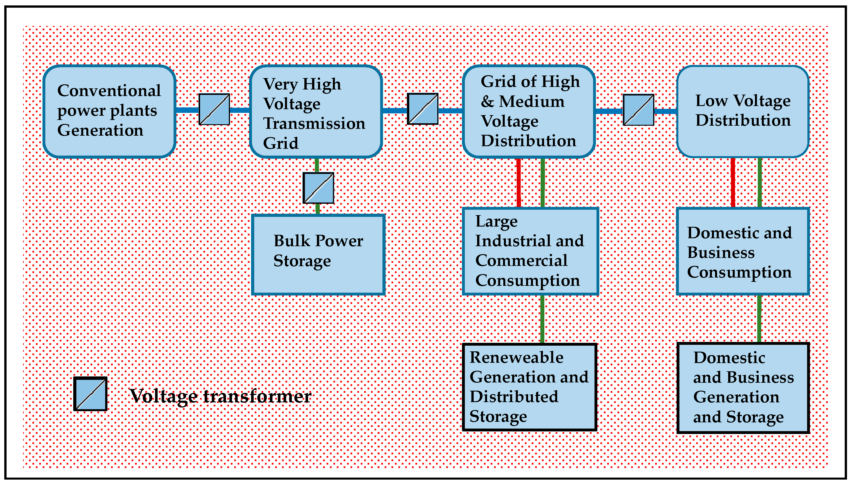
Figure 2.
Graphic representation of the Power-to-Gas scheme, integrating the electrical and gas grids with reversing conversions, providing existing services and incorporating both storage capacities.
Figure 2.
Graphic representation of the Power-to-Gas scheme, integrating the electrical and gas grids with reversing conversions, providing existing services and incorporating both storage capacities.
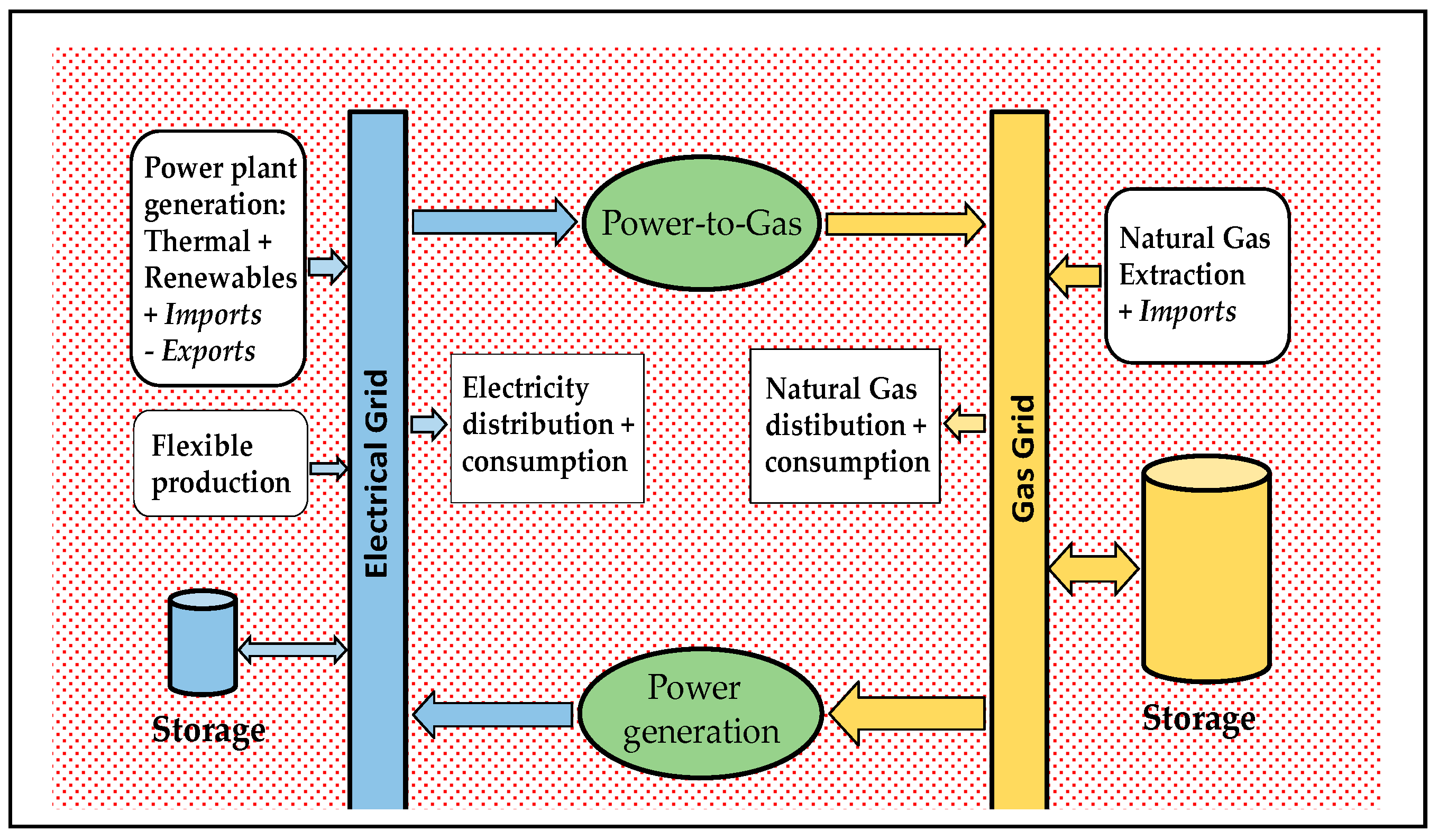

Table 1.
Some tested and performing technical solutions to provide energy storage to service the electric grid (References [21,22,23,24]).
| PHS | Flywheel | TES | Li Ion Battery | RFB | H2 Fuel Cell | |
|---|---|---|---|---|---|---|
| Power rate MW | <5000 | <20 | <300 | <50 | <1.5 | <50 |
| Power density W/kg | ≈0.15 | 400–1600 | 10–30 | 100–5000 | 150 | 5–500 |
| Energy density kWh/m3 | ≈1 | 20–80 | 80–250 | 200–600 | 20–70 | 500–3000 |
| Response time | minute | <second | minutes | <second | second | <minute |
| Ramp-up time | minutes | seconds | hour | programmable | minute | hour |
| Discharge hour | 10–100 | <0.25 | 1–24 | 0.1–8 | <8–24 | <24 |
| Lifetime years | 40–100 | 15–20 | 10–40 | 5–20 | 5–20 | 5–25 |
| Durability cycles | 10,000–30,000 | >20,000 | 2000–15,000 | 1000–10,000 | >13,000 | 1000–20,000 |
| Energy efficiency | 70%–85% | 80%–95% | 30%–60% | 85%–95% | 65%–85% | 35%–45% |
| Maturity | Fully mature | Mature | Early commercial | Mature | Early commercial | Demonstration |
| Applications | Load leveling | Power quality, UPS | Time shifting | Power quality, Electric vehicle | Network Efficiency | Time shifting |
Table 2.
Tested and performing fuel-cells types that provide energy services to the electric grid, off-grid and automotive power (References [27,28,29]).
| PEM | AFC | PAFC | MCFC | SOFC | |
|---|---|---|---|---|---|
| Operating Temperature | 50–100 °C | 50–200 °C | 150–220 °C | 600–700 °C | 650–1000 °C |
| Electrolyte | Organic polymer membrane | Alkaline aqueous solution | Liquid phosphoric acid | Molten carbonate in ceramic matrix | Yttria stabilized Zirconia |
| Charge carrier | H+ | OH− | H+ | CO32− | O2− |
| Cathode catalyst | Platinum | Platinum | Platinum | Nickel | Perovskites |
| Primary Fuel | H2 | H2 | H2 | H2 , CO, CH4 | H2, CO, CH4 |
| Start-up time | minute | minute | hour | hour | hour |
| Durability hour | 5000–10,000 | 5000–8,000 | 15,000–20,000 | 20,000–30,000 | 45,000 |
| Power density kW/m3 | ≈5 | ≈1 | ≈1 | ≈2 | ≈1 |
| Electric efficiency | 40%–60% | 45%–65% | 35%–50% | 45%–60% | 40%–60% |
| Combined heat & power Eff. | 55%–90% | 55%–80% | 55%–90% | 60%–90% | 60%–90% |
| Primary applications | Backup power & Distributed generation & Automotive | Space & Automotive | Distributed generation, Automotive | Distributed generation | Distributed generation & Automotive |
© 2017 by the author. Licensee MDPI, Basel, Switzerland. This article is an open access article distributed under the terms and conditions of the Creative Commons Attribution (CC BY) license (http://creativecommons.org/licenses/by/4.0/).
Share and Cite
MDPI and ACS Style
Rosa, R.N. The Role of Synthetic Fuels for a Carbon Neutral Economy. C 2017, 3, 11. https://doi.org/10.3390/c3020011
AMA Style
Rosa RN. The Role of Synthetic Fuels for a Carbon Neutral Economy. C. 2017; 3(2):11. https://doi.org/10.3390/c3020011
Chicago/Turabian StyleRosa, Rui Namorado. 2017. "The Role of Synthetic Fuels for a Carbon Neutral Economy" C 3, no. 2: 11. https://doi.org/10.3390/c3020011
Note that from the first issue of 2016, this journal uses article numbers instead of page numbers. See further details here.