Review

Wavelet-Based Adaptive Eddy-Resolving Methods for Modeling and Simulation of Complex Wall-Bounded Compressible Turbulent Flows

1
Convergent Science Inc., Madison, WI 53705, USA
2
Engineering Department, University of Campania Luigi Vanvitelli, 81031 Aversa, Italy
3
Department of Mathematics, Florida State University, Tallahassee, FL 32306, USA
4
Keldysh Institute of Applied Mathematics of Russian Academy of Sciences, 125047 Moscow, Russia
5
Adaptive Wavelet Technologies LLC, Superior, CO 80027, USA
*
Author to whom correspondence should be addressed.
This author performed the presented work at Florida State University.
Fluids 2021, 6(9), 331; https://doi.org/10.3390/fluids6090331
Submission received: 29 July 2021 / Revised: 6 September 2021 / Accepted: 10 September 2021 / Published: 15 September 2021
(This article belongs to the Special Issue Wavelets and Fluids)

Abstract

:
This article represents the second part of a review by De Stefano and Vasilyev (2021) on wavelet-based adaptive methods for modeling and simulation of turbulent flows. Unlike the hierarchical adaptive eddy-capturing approach, described in the first part and devoted to high-fidelity modeling of incompressible flows, this companion paper focuses on the adaptive eddy-resolving framework for compressible flows in complex geometries, which also includes model-form adaptation from low to high fidelity models. A hierarchy of wavelet-based eddy-resolving methods of different fidelity has been developed for different speed regimes, various boundary conditions, and Reynolds numbers. Solutions of various fidelity are achieved using a range of modeling approaches from unsteady Reynolds-averaged Navier–Stokes simulation to delayed detached eddy simulation, wall-modeled and wall-resolved large eddy simulations. These novel methodologies open the door to construct a hierarchical approach for simulation of compressible flows covering the whole range of possibilities, from only resolving the average or dominant frequency, to capturing the intermittency of turbulence eddies, and to directly simulating the full turbulence spectrum. The generalized hierarchical wavelet-based adaptive eddy-resolving approach, once fully integrated into a single inherently interconnected simulation, results in being a very competitive and predictive tool for complicated flows in industrial design and analysis with high efficiency and accuracy.

Graphical Abstract

1. Introduction

Accurate modeling of compressible turbulent flows required in aerospace industry, including aeronautical and rotorcraft engineering, turbomachinery, automotive and railway transportation, energy and several technology-related industries, continues to be one of the major challenges in developing simulation-based predictive tools that can be used for design and analysis of fluid engineering systems and/or their components [1]. Compared to the low-Mach number incompressible regime, the computational fluid dynamics of high-speed compressible flows is further complicated by significant variations of the fluid thermodynamic properties. The highest fidelity method, i.e., direct numerical simulation (DNS) remains computationally prohibitive for moderate to high Reynolds-number flows, due to the need to resolve an extremely wide range of length and time scales that results in computational requirements exceeding current capabilities. The number of grid points (degrees of freedom) required for DNS is proportional to either R e 9 / 4 , based on the large eddy characteristic velocity and length scales [2], or R e 37 / 14 , based on the stream-wise domain size [3]. Due to the high accuracy requirements for the spatial discretization, spectral methods [4] and compact finite difference methods [5] are the most popular numerical schemes for DNS. However, their applications to complex geometries in realistic engineering problems are still limited. Therefore, more efficient numerical methods than DNS are of great interest in simulations of large scale complex flows.
In order to increase the computational efficiency of turbulent flow simulations and substantially improve the accuracy of predictions of fluid flow characteristics, a number of wavelet-based adaptive numerical methodologies [6,7,8] that explore unique properties of wavelet analysis to unambiguously identify and isolate localized flow structures have been developed. These methods allow to fully utilize spatial/temporal turbulent flow intermittency and to tightly integrate numerics and physics-based turbulence modeling [9,10,11,12], while resolving dynamically dominant flow structures with an active error control and ensuring better capture of the flow physics on a nearly optimal adaptive computational grid, ultimately leading to substantial reduction in the computational cost. Specifically, for the results reported in Refs. [12,13,14,15,16,17], the reduction of grid points number results in being above 90% for most of three-dimensional (3D) cases, compared to the full mesh at the highest level of resolution.
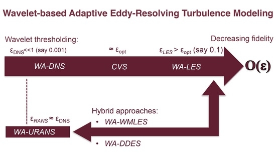
Furthermore, tight integration of wavelet-based adaptive numerical methods with turbulence modeling allows to construct a hierarchical eddy-capturing framework for simulating compressible turbulent flows, where coherent flow structures are either totally or partially resolved on self-adaptive computational grids, while modeling the effect of unresolved motions, wherever it is appropriate. The separation between resolved (more energetic, coherent) eddies and residual (less energetic, coherent/incoherent) flow structures is achieved by means of the nonlinear wavelet thresholding filter (WTF). The value of wavelet threshold controls the relative importance of resolved field and residual background flow and, thus, the fidelity of turbulence simulations. By increasing the thresholding level, a unified hierarchy of wavelet-based eddy-capturing turbulence models of progressively lower fidelity is obtained, namely, the wavelet-based adaptive direct numerical simulation (WA-DNS) [12], the coherent vortex simulation (CVS) [18], and the wavelet-based adaptive large eddy simulation (WA-LES) [11,19,20,21].
A distinct advantage of this adaptive eddy-capturing framework is that the overall physical fidelity of the simulation can be simply controlled by the WTF strength [22,23], thereby providing a hierarchical modeling framework that allows continuous transition among the various fidelity regimes. In fact, transition from WA-DNS to CVS, and to WA-LES, is well established through controlling the wavelet threshold. WA-DNS uses wavelet-based discretization of the (unfiltered) Navier–Stokes equations to dynamically adapt the local resolution on intermittent flow structures [24,25]. Transition from WA-DNS to CVS is achieved by using an optimal wavelet threshold [18], resulting in the decomposition of the flow field into coherent and incoherent contributions. For WA-LES, the wavelet threshold is further increased so that the stochastic and the least energetic coherent portion of the turbulent solution are discarded, and only the most energetic part of the coherent vortices are captured in the resolved field [19]. In WA-LES, the discarded subgrid-scale (SGS) coherent structures dominate the total SGS dissipation to be modeled [26,27]. Therefore, similar to conventional non-adaptive LES, deterministic closures [28,29] are applicable for WA-LES by modeling SGS coherent structures in terms of resolved energetic coherent vortices. A recent comprehensive review about the hierarchical adaptive eddy-capturing approach for modeling incompressible turbulent flows can be found in Ref. [30].
As far as the simulation of wall-bounded high Reynolds-number flows is concerned, the reliable and computationally efficient prediction of the effects of near-wall turbulence still represents the major challenge for the turbulence modeling community. Recently, a number of wall-modeled and wall-resolved wavelet-based adaptive approaches have been developed [14,16,31,32]. Several attempts for the application of the wavelet-based methods have been carried out for both wall-modeled and wall-resolved simulations. In the latter case, the wall region is fully resolved by the wavelet-based adaptive computational mesh and no wall model is needed. Thus, the wall-resolved WA-LES [14] can be directly applied. However, even with wavelet-based grid adaptation, the computational cost of wall-resolved simulations at high Reynolds numbers is prohibitively high. Thus, the Reynolds-averaged Navier–Stokes (RANS) modeling approach is still of great importance in engineering applications. The capabilities of the recently developed wavelet-based adaptive unsteady RANS (WA-URANS) method [16,31,32] have been demonstrated for a variety of two-dimensional (2D) and three-dimensional (3D) high Reynolds-number complex geometry flows, for different speed regimes and various boundary conditions.
Although the RANS methods are very popular in a wide range of industrial applications, more accurate simulations become more and more demanding in some areas, especially considering the fast development of high performance computing [1]. To compromise the accuracy and efficiency between the wall-resolved LES and RANS approaches, the wall-modeled LES has drawn great attention in the last two decades. In fact, as estimated by Choi and Moin [3], the computational complexity of the wall-resolved LES approach scales as ∼ R e 13 / 7 , whereas for the wall-modeled LES [33,34] it scales as ∼ R e . Therefore, the latter approach is more applicable to high Reynolds number problems, despite some side-effects, such as the log-layer mismatch (LLM). Due to LLM, where near-wall RANS and resolved LES away from the wall do not quite match their interception constants in the log-law layers, the error in skin friction of about 5% to 15% is observed [35,36,37].
There are three well-known categories of wall-modeled LES methods: (1) the hybrid LES/RANS methods [38,39,40,41], (2) the Detached-Eddy Simulation (DES) methods [35,36,42,43] and (3) the wall-shear-stress modeled methods [44,45,46,47,48]. Both the first two categories switch to RANS formulation in the inner layer of the wall region. The hybrid LES/RANS methods usually use a RANS closure model in the near-wall region and an LES approach away from the wall. In this category, the terms zonal and nonzonal are used to identify different methods. For zonal methods, a RANS zone is specified in advance, whereas nonzonal methods usually use a blending function to interpolate between RANS and SGS turbulent stresses. Note that in the DES community, DES methods are usually also referred to as hybrid LES/RANS methods. However, the DES approach appears to have a more “seamless” inter-model transition based on length scale that switches to either a RANS formulation or the general LES closure model, and can be considered as a unified closure model throughout the domain [49]. Finally, the wall-shear-stress methods model the wall shear stress directly on the wall by performing a RANS computation on a separate boundary layer mesh and returning wall stress and heat flux as boundary conditions for the large eddy simulation.
To build a framework for the application of wall-modeled LES approaches in the wavelet-based adaptive methodology, the first question to address is how the WA-LES and WA-URANS can coexist in a single simulation. The transition from WA-LES to WA-URANS is not as straightforward as the aforementioned transition from WA-DNS to CVS, and to wall-resolved WA-LES. In the compressible RANS modeling framework, the unknown variables represent mean (Reynolds- or Favre-averaged) quantities, which are smooth and whose evolution is simulated by modeling the mean effects of turbulent stresses. In fact, as shown in Refs. [16,32], the accurate solution of the WA-URANS equations requires wavelet threshold values as small as the ones used in WA-DNS. This is counterintuitive when looking at the increasing fidelity regime for monotonically decreasing WTF level, as previously discussed. However, although a low level of wavelet threshold is used to achieve high numerical accuracy, the smooth mean solution of the governing equations turns out to be supported by a relatively coarse adaptive mesh, regardless how fine the mesh at the highest permitted level of resolution is.
To develop a hybrid, mathematically consistent approach with coexistence and connection between WA-URANS and WA-LES approaches, the wavelet-based adaptive delayed detached eddy simulation (WA-DDES) formulation was recently proposed [15,50]. A variable wavelet thresholding strategy was used to blend a very small wavelet threshold in the WA-URANS region with a relatively large value in the WA-LES region. The developed wavelet-based adaptive extension allows to achieve both accuracy and efficiency in terms of degrees of freedom used in WA-DDES compared to the wall-resolved WA-LES. However, the stringent restriction on the time integration step caused by the CFL-type [51] condition still remains to be a major issue for WA-DDES computations. In fact, despite the use of highly stretched meshes with relatively large spacings in the wall-parallel directions to reduce the total number of active nodes, a relatively small wall-normal mesh spacings are employed in the region immediately adjacent to the wall, i.e., where y + < 1 . To overcome this restriction, the new wavelet-based adaptive wall-modeled LES (WA-WMLES) method has been introduced in Ref. [17], where the outer-layer WA-LES is supplied with a compressible equilibrium wall-stress model, so that the first mesh point away from the wall may be located at y + 40 , thus, relieving the time step restriction.
The development of WA-URANS, WA-DDES, and WA-WMLES, as well as (wall-resolved) WA-LES practically covers the full spectrum of wall-bounded turbulence modeling approaches. Along with WA-DNS and CVS, these methods serve as segregated steps towards the construction of a unified wavelet-based adaptive hierarchical eddy-resolving framework for modeling complex wall-bounded compressible turbulent flows, capable of performing simulations with various fidelity, from no-modeling DNS to full-modeling RANS, depending on the requirement and balance of accuracy and computational efficiency.
In the hierarchical adaptive eddy-capturing approach [30] the form of governing equations is kept unchanged and the transition between models of different fidelity is achieved through modifying the WTF level. The adaptive eddy-resolving framework, discussed in this review, incorporates a wider class of methods that not only utilize different wavelet thresholds but also include different governing equations with model-form adaptation. In particular, the combination of these two features facilitates the development of wavelet-based adaptive wall-modeled approaches. The present work represents the original attempt at systematically expanding the application of the wavelet-based adaptive methodology for accurate and efficient predictions of complex wall-bounded turbulent flows.
The rest of the paper is organized as follows. Section 2 introduces the wavelet-based Favre filtered/averaged Navier–Stokes equations. In Section 3, the wavelet-based method that is used for the numerical implementations is described. Section 4 and Section 5 describe wall-resolved and wall-modeled methods, respectively, with discussion of key concepts, advantages/disadvantages of each method, as well as simulation examples. Finally, some concluding remarks are given in Section 6.

2. Wavelet-Favre Filtered/Averaged Navier–Stokes Equations

In this section, the wavelet-based Favre filtered/averaged Navier–Stokes equations for compressible turbulent flows are presented. For simplicity, Favre filtered equations for LES computations and Favre averaged equations for RANS computations are combined into a common form, with explanation of meanings of the integrated variables and modeled terms for the two distinguished formulations.
WA-LES is formulated in terms of wavelet-based spatially filtered variables. For conventional non-adaptive LES, the implicit or explicit linear lowpass filtering operator is usually defined a priori and is tied to the corresponding computational mesh, with under-resolved mesh spacings relative to DNS. In contrast to standard LES, the spatial filter used in WA-LES is constructed by employing the WTF operator described in Section 3, which is nonlinear and depends on the instantaneous flow realization. In the following, the WTF operator is denoted by ( · ) ¯ > ϵ , where ϵ stands for the prescribed level of thresholding. Similarly to the conventional lowpass-Favre filter for variable density flows, the wavelet-Favre filter is defined by ϕ ^ > ϵ = ρ ϕ ¯ > ϵ / ρ ¯ > ϵ . This way, the wavelet-Favre filtered Navier–Stokes equations involve the following primitive variables: ρ ¯ > ϵ , p ¯ > ϵ , u i ^ > ϵ , T ^ > ϵ and e ^ > ϵ , representing, respectively, wavelet-filtered density and pressure, together with wavelet-Favre filtered velocity, temperature and total energy (per unit mass).
Differently, WA-URANS is formulated in terms of Reynolds-averaged and Favre-averaged dependent variables. Denoting Reynolds-averaging and Favre-averaging operations as ϕ and { ϕ } = ρ ϕ / ρ , respectively, where ϕ stands for a generic physical variable, the method involves ρ and p , together with { u i } , { T } , and { e } . Note that, in this context, since a very low level of wavelet thresholding is used, the effect of WTF is practically negligible, and the corresponding operator symbol is omitted in the notations of Reynolds/Favre-averaged primitive variables.
Furthermore, WA-DDES is formulated in terms of both Reynolds-averaged and spatially (wavelet) filtered quantities, which exist simultaneously in this hybrid modeling framework. In fact, the family of eddy-resolving DES models is better described in terms of length scale formulations [49], where either Reynolds-averaged in the near-wall region (referred to as RANS region) or low-pass wavelet-filtered Navier–Stokes equations away from the wall (LES region) are solved. DES results in being, essentially, an eddy-resolving method everywhere as it has to be ensemble-averaged to obtain meaningful statistical quantities. Significant levels of fluctuations are usually observed, even in the RANS regions of the flow domain. Therefore, in WA-DDES, all dependent variables can be interpreted as Favre-filtered quantities.
For the sake of clarity, the simple symbols ρ , p, u i , T and e are used hereafter to denote the resolved primitive variables for either WA-LES or WA-URANS formulations, including WA-WMLES and WA-DDES. Therefore, the wavelet-Favre filtered/averaged Navier–Stokes equations governing the balance of mass, momentum, and energy in compressible flows of a calorically perfect gas, supplied with modeled turbulent terms, can be written in the following general form:
ρ t + ( ρ u j ) x j = 0 ,
ρ u i t + x j ρ u i u j = p x i + τ ^ i j x j ,
ρ e t + x j ρ e + p u j = x j u i τ ^ i j q j ,
where
p = ρ R T ,
e = 1 2 u i u i + p ρ ( γ 1 ) ,
q j = c p μ Pr + μ T Pr T T x j ,
τ ^ i j = 2 μ S ˜ i j τ i j ,
S ˜ i j = S i j 1 3 u k x k δ i j , S i j = 1 2 u i x j + u j x i .
The parameter R stands for the gas constant, while c p and c v are the specific heats at constant pressure and volume, respectively, where the specific heat ratio γ = c p / c v = 1.4 for diatomic gases is assumed. The term q j represents the sum of molecular and modeled turbulent heat fluxes, with Pr = μ c p / λ being the Prandtl number, where λ is the thermal conductivity, and Pr T the turbulent Prandtl number. In this work, these two parameters are assumed constant, being set to Pr = 0.72 and Pr T = 0.9 , respectively. Note that the temperature dependent molecular dynamic viscosity μ is given by the Sutherland’s law. The turbulent eddy viscosity is denoted by μ T , which is unknown and needs a turbulence model for closure. The term τ ^ i j is the sum of molecular and modeled stress tensors, while S i j is the mean strain-rate tensor, with S ˜ i j representing the associated deviatoric part, δ i j is the Kronecker delta, and the summation convention for repeated indices is assumed.
The definition of the stress tensor depends on the formulation that is applied. In WA-LES, where the wavelet-Favre filtered equations are considered, the SGS stress tensor is defined as
τ i j = ρ u i nf u j nf ^ > ϵ u i u j ,
where the unclosed term u i nf u j nf ^ > ϵ involves the unfiltered velocity u i nf . In WA-URANS, where the Favre averaged equations are considered, the Reynolds stress tensor is written as
τ i j = ρ u ˜ i u ˜ j u i u j ,
where the unclosed term { u ˜ i u ˜ j } involves the instantaneous velocity u ˜ i . Regardless of the formulation, the residual stress tensor is modeled according to the eddy-viscosity assumption, namely,
τ i j = 2 μ T S ˜ i j ,
so that τ ^ i j = 2 μ + μ T S ˜ i j holds for the total stress tensor (7). All the details about the governing equations and turbulence closure models can be found in the reference articles for the different approaches that are WA-LES [14], WA-URANS [16], WA-DDES [15], and WA-WMLES [17].

3. Adaptive Wavelet Collocation Method

Regardless of the adopted formulation, the governing equations described in the previous section are numerically solved using the parallel adaptive wavelet-collocation (AWC) method [7]. This method is based on multi-resolution wavelet analysis to construct time-dependent computational meshes with spatially varying resolution that is required to adequately resolve the localized structures of the solution with a priori prescribed accuracy. From previous studies on different wavelet-based turbulence modeling methods for linearly forced homogeneous turbulence [10] and supersonic channel flow [15] the Reynolds number scaling of wavelet-based adaptive methods is considerably slower than cubic, i.e., R e 3 , required for the non-adaptive DNS. However, further investigation on the R e scaling of the models in wavelet-based eddy-resolving hierarchy at very high Reynolds numbers remains to be done, in order to apply the wavelet-based methods to practical industrial flows.
Formally, the mesh adaptation is based on the analysis of wavelet decomposition of a spatially dependent field, say u ( x ) , sampled on a set of dyadic nested collocation points x k j at different levels of resolution j, formally written as
u ( x ) = l L 1 c l 1 ϕ l 1 ( x ) + j = 2 J μ = 1 2 n 1 k K μ , j d k μ , j ψ k μ , j ( x ) ,
where n denotes the number of spatial dimensions, bold subscripts denote n-dimensional indices, while L 1 and K μ , j are n-dimensional index sets associated with scaling functions ϕ l 1 and different family wavelets ψ k μ , j , respectively. Each of the basis functions, i.e., ϕ l 1 or ψ k μ , j , has one-to-one correspondence with a mesh point l L 1 or k K μ , j . Scaling functions ϕ l 1 carry the averaged signal, while the multi-dimensional second-generation wavelet functions ψ k μ , j define local, variational details. The amplitudes are given by the coefficients c l 1 and d k μ , j , respectively, and hence have a unique correspondence to mesh points. The levels of resolution span over 1 j J , with 1 and J being respectively the coarsest and finest levels of resolution present in the approximation. During the wavelet transform, detail (or wavelet) coefficients d k μ , j are obtained recursively from scaling function coefficients c k μ , j , from level J to 2. After the wavelet transform, the coefficients c l 1 ( l L 1 ) and d k μ , j ( k K μ , j ) are stored, respectively, at the mesh points of the coarsest ( j = 1 ) and higher ( 2 j J ) levels of resolution. Note that for n-dimensional space, there are ( 2 n 1 ) families of wavelet functions, which are indexed by μ .
Wavelet-based filtering arises naturally from the series expansion (12). The WTF operation is performed by applying the wavelet transform to the original field u ( x ) , zeroing the wavelet coefficients below a given threshold, say ϵ = ϵ ( x , t ) for generality, and transforming back to the physical space. The resulting approximate field, say u > ϵ ( x ) , composed of a subset of the original wavelets, represents the dominant modes and can be formally written as the following conditional series:
u > ϵ ( x ) = l L 1 c l 1 ϕ l 1 ( x ) + j = 2 J μ = 1 2 n 1 k K μ , j | d k μ , j | > ϵ u ( x ) d k μ , j ψ k μ , j ( x ) .
In many implementations, the filter threshold is taken to be relative to some characteristic scale, often represented by either the L 2 or L norm of u ( x ) taken globally over the domain and denoted as u ( x ) [19]. The resulting nonlinear filtering operation practically separates resolved flow structures and unresolved residual motions, where, for a properly normalized threshold, the reconstruction error of the filtered variable is shown to converge as
u > ϵ u C ϵ u ,
with C = O ( 1 ) [52].
The dynamic mesh adaptation is tightly coupled with WTF, because, due to the one-to-one correspondence between wavelets and grid points, the nodes are omitted from the computational mesh if the associated wavelets are excluded from the truncated approximation (13). Indeed, the multilevel structure of the wavelet approximation provides a natural way to obtain the solution on a nearly optimal numerical mesh, which is dynamically adapted to the evolution of the main flow structures, both in location and scale, while higher resolution computations are carried out in the regions where (and only where) steep gradients in the resolved flow field occur. The multi-resolution wavelet decomposition (13) is used for both mesh adaptation and interpolation, while the derivatives at the adaptive computational nodes are found by differentiation of the local wavelet interpolant at appropriate level of resolution [6,53].
It is worth noting that per-point cost of adaptive simulations is about three times more expensive for the AWC method with respect to corresponding non-adaptive simulations, which makes the adaptive method in principle outperform the corresponding non-adaptive one when less than one third of the mesh points are retained in the calculation or, equivalently, the grid compression ratio exceeds 67%. Based on the results reported in previous works [12,14,15,16,17], typical compression ratios above 90% are observed for most 3D cases.
The second-generation wavelet bases described above rely on topologically rectilinear meshes and inherently isotropic mesh elements. This restriction puts some limitations on the applicability of the approach for simulation of complex geometry wall-bounded turbulent flows. These limitations were recently overcome with the development of the anisotropic AWC (A-AWC) method [54]. This enhanced formulation preserves active error-controlling properties of the original method [6,7,53,55], but provides the additional flexibility to control mesh anisotropy and to solve flow problems in complex domains. In practice, by separating the computational space from the physical one and introducing a mapping between them, the use of anisotropic curvilinear meshes in complex geometries is permitted. At the same time, the structured rectilinear assembly of collocation points in the computational space is retained, which allows the use of computationally efficient discrete adaptive wavelet transform and derivative approximations. A-AWC utilizes a general curvilinear coordinate mapping function x ( ξ ) , which can be either continuous or discrete. The mapping coordinates are viewed as additional variables, which can be adapted on and differentiated in computational space, thus, allowing the construction of the Jacobian matrix
J i j x i ξ j .
Spatial derivatives in physical space are evaluated numerically as
x i = ξ j x i ξ j = J i j 1 ξ j ,
where J i j 1 is the inverse Jacobian matrix.

4. Wall-Resolving Approach

The WA-LES approach was extended for computational modeling of compressible wall-bounded attached turbulent flows in [14], where the wavelet-Favre filtered compressible Navier–Stokes equations were derived. According to the wall-resolving approach, the spatial mesh was highly stretched in the wall-normal direction, with mesh spacings at the highest level of resolution practically corresponding to DNS-like resolution. Indeed, efficient and accurate calculations were permitted by the use of A-AWC method for the numerical implementation. The unknown SGS stresses (9), together with the other unclosed terms in the governing equations, were approximated by means of eddy-viscosity/conductivity models based on the anisotropic minimum-dissipation (AMD) approach, which has low computational complexity while being particularly suitable for anisotropic grids [56].
The performance of compressible WA-LES was assessed by conducting wall-resolved simulations of fully developed supersonic turbulent flow in a plane channel with isothermal cooled walls, at different Mach and Reynolds numbers [14]. This flow configuration represents a well-established benchmark for wall-bounded turbulent compressible flows [57]. In Figure 1, an example of instantaneous adapted grid, colored by the thermal field normalized by the wall temperature, is reported for the flow case at M a = 1.5 and R e = 3000 , which was simulated by prescribing ϵ = 2.5 × 10 2 for WTF. As was expected, the spatial mesh resulted in being highly refined around localized flow structures. It is worth noting that the choice of the uniform level of thresholding is very important, especially when no explicit filtering operation is performed and the pure built-in filtering effect of AWC is exploited [21]. This parameter was selected as a fair compromise to ensure the necessary numerical accuracy, while keeping acceptable the computational cost. The detailed discussion of how the WTF level affected the compressible WA-LES solution was also included in [14].
Both feasibility and effectiveness of WA-LES in the high-speed compressible regime were demonstrated by making a comparison with reference DNS [57] and LES [58] of the same flow. The mesh resolution and some mean flow results for the three different solutions are presented in Table 1, where the subscript c is used to indicate values at the channel center. Note that, for WA-LES, while the resolution corresponding to an equivalent non-adaptive grid is shown for the two homogeneous directions, the minimum mesh spacing in the wall normal direction actually corresponds to the finest mesh that was employed in the simulation. The friction Reynolds and Mach numbers, R e τ and M a τ , as well as the heat flux coefficient, B q , were reasonably predicted, consistently with non-adaptive LES data. Very importantly, the good agreement with reference DNS was obtained by retaining less than 4 % of the AWC points at the highest level of resolution. As illustrated in Figure 2, where the profiles of normalized mean density, temperature, and streamwise momentum are shown, WA-LES was able to almost perfectly reproduce mean flow features, which is fully consistent with reference LES data [58]. Moreover, turbulent flow statistics were well predicted, as demonstrated by the profiles of turbulent shear stress and mean square temperature fluctuation depicted in Figure 3. The accuracy of resolved turbulent fluctuations in the wall region demonstrated an important feature of compressible WA-LES. Close to the wall, owing to the automatic grid adaptation, the presence of high gradients in the mean flow-field variables, along with significant turbulent fluctuations, leaded to the use of refined grids. This fact must be taken into consideration when making a comparison between WA-LES and LES resolutions. Indeed, this behavior contributed to retain energy at high wavenumbers and caused the correspondingly increased local resolution with respect to conventional lowpass filter-based LES. In contrast, in the central region of the channel, due to the slowly spatially varying mean flow and less significant turbulence, coarser grids were employed in the calculation.

5. Wall-Modeling Approaches

This section reviews three different wall-modeled methods attempting to deal with wall-bounded compressible turbulent flows with complex geometries, different speed regimes, various boundary conditions, at moderate to high Reynolds numbers.

5.1. Wavelet-Based Adaptive Unsteady Reynolds-Averaged Navier–Stokes

In contrast to conventional non-adaptive RANS modeling, where the mesh is specified a priori, the WA-URANS approach uses dynamically adaptive meshes, where the finest allowed grid resolution could be considerably smaller [16,31,32]. This implies that grid convergence is automatically achieved as long as the wavelet threshold is sufficiently small, as follows from the estimate (14), which guarantees that the error of the adaptive numerical solution with respect to the corresponding solution on non-adaptive computational mesh, at the highest level of resolution, is bounded by the wavelet threshold. In fact, a relatively small threshold (⪅ O ( 10 3 ) ) must be used for WA-URANS, since the unknown mean variables in the governing equations have to be solved accurately. One interesting feature of WA-URANS is its ability to check whether the solution converges to the mean flow results of conventional RANS, when very small grid spacings are allowed in both wall-normal and wall-parallel directions, which is quite expensive for non-adaptive simulations, whereas an accurate A-AWC solution can be obtained in a very efficient manner.
The accuracy and efficiency of WA-URANS simulation for a given highly refined mesh and a priori prescribed level of thresholding is demonstrated for 2D simulations of a subsonic zero pressure gradient flat plate boundary layer (BL) [16]. The flow configuration corresponds to the case found on the NASA Turbulence Modeling Resource website (https://turbmodels.larc.nasa.gov/flatplate.html (accessed on 16 June 2021)). Results of the study of the dependence on the wavelet threshold, in terms of mesh size and predicted skin friction at a given streamwise location, are listed in Table 2, compared with the NASA CFL3D results using the Spalart-Allmaras (SA) model [59] and the non-adaptive full mesh with all grid points at the highest level of resolution. Therefore, the error introduced by the wavelet-based adaptation is the relative difference between the WA-URANS and the CFL3D non-adaptive simulations. As expected, the mesh size increases with decreasing threshold, while the error of skin friction C f decreases. Also, note that the error magnitudes are of the expected order of 10 3 . This shows that a smooth mean solution of the RANS equations can be accurately represented by a quite coarse adaptive mesh, compared to the solution on the finest non-adaptive mesh. WA-URANS was also tested for more complex flows for subsonic and transonic speeds [16]. For the latter case, an anisotropic extension of the original wavelet-based shock capturing scheme [60] was used in the proximity of the shock.
A benchmark case for subsonic flows with shape induced separation involved a wall-mounted hump geometry, also known as 2D NASA hump case, representative of the upper surface of an airfoil. This actually represents a NASA standard test case, for which the original experimental study was reported in Ref. [61]. The computational configuration mainly followed the NASA 2004 CFD validation workshop [62], where it represented the baseline validation case with no plenum for flow control. The hump chord based Reynolds number was relatively high, around one million, while the far field Mach number was M a = 0.2 . The resulting velocity field and adaptive mesh are depicted in Figure 4 and Figure 5, respectively. Apparently, local mesh refinement is located at the separation shear layer, where mesh cells are nearly isotropic. The skin friction and pressure coefficient over the bottom wall are plotted in Figure 6, for both WA-URANS and conventional RANS obtained with the NASA CFL3D code [62], supplied with the SA model, compared to experimental findings. Both numerical solutions fail in predicting the separation bubble size, showing the reattachment point at X / c 1.26 , whereas experiments provided X / c 1.1 .
Furthermore, a benchmark case for transonic flows with shock induced separation was represented by the so-called Bachalo-Johnson flow. The original experiments [63] for this flow had an axisymmetric bump placed over a cylinder aligned with a wind tunnel and adjusted to produce a shock wave, which resulted in the turbulent BL separation. The Reynolds number based on the bump chord was R e c = 2.763 × 10 6 and the far field free-stream Mach number was M a = 0.875 .
The mean streamwise velocity contours and the corresponding adaptive mesh are depicted in Figure 7 and Figure 8, respectively. Apparently, the major local mesh refinement is concentrated in the shock region, while another region of local mesh refinement can be seen just on the bump surface, say, at 0.2 < x < 0.5 . In fact, this is a favorable pressure gradient region with relatively thinner BL thickness and, hence, sharper gradients of the velocity occur than those of other attached flow regions. The skin friction and pressure coefficients over the bottom wall are plotted in Figure 9, where the conventional RANS and WA-URANS predictions are very close to each other. Compared with the available pressure distribution provided by the experiments, the predicted shock locations by both RANS methods were observed downstream of the measured location. In addition, the separation bubble correlated with the pressure distribution was poorly predicted.
Although the WA-RANS methods can handle complex turbulent flows at high Reynolds numbers with coarse adaptive mesh and very fine effective mesh resolution, for a given accuracy, both the subsonic flow over the hump and transonic flow over the bump cases showed an inherent “bottle-neck” of the RANS approach in capturing the mean field of the turbulent flow separation. This issue can be addressed by eddy-resolving turbulence modeling methods, such as the WA-DDES and WA-WMLES methods discussed in the next sections.

5.2. Wavelet-Based Adaptive Delayed Detached Eddy Simulation

The WA-DDES approach for wall-bounded compressible turbulent flows was developed in Ref. [15], where its effectiveness was demonstrated for flow simulations using the SA model based formulation [35]. WA-DDES exploits a variable wavelet thresholding strategy by blending two distinct reference thresholds, which are completely different for WA-URANS and WA-LES regimes. In fact, on one hand, the accuracy of WA-URANS solution would be lost if the aggressively high level of thresholding typical to WA-LES were used. On the other hand, WA-LES would automatically switch to WA-DNS, if the very low level of thresholding typical to WA-URANS were prescribed, which is also unacceptable. Since the original DDES model already makes use of a blending function [35], which switches between the length scales in LES and RANS regions, and serves as a good indicator between the two regions, it is natural to use the same blending function, say f d , for defining the actual threshold in WA-DDES computations. This way, by interpolation between the two limit values, say ϵ RANS and ϵ LES , the following hybrid threshold,
ϵ hyb = ( 1 f d ) ϵ RANS + f d ϵ LES ,
was used to perform A-AWC grid adaptation. For example, Figure 10 shows the instantaneous blending function contours for WA-DDES of supersonic channel flow, where RANS and LES regimes practically correspond to blue and red zones, respectively.
In addition to wavelet threshold blending, a split mesh adaptation strategy on mean and fluctuating quantities, with two different WTF levels, helped to further reducing the total number of retained AWC points and, thus, the computational cost of the simulations. Decomposition of the fields into mean and fluctuating parts resulted in the corresponding decomposition of the wavelet coefficients in (13), specificallly,
d k μ , j = d ¯ k μ , j + d k μ , j
where d ¯ k μ , j and d k μ , j represent mean and fluctuating components, respectively. As a consequence, the thresholding criterium was replaced by
| d ¯ k μ , j | > ϵ 1 u ( x ) , | d k μ , j | > ϵ 2 u ( x )
where u and u represent the mean and fluctuating components of u. The splitting strategy provided a tighter control on the grid adaptation process, while being more flexible than the one based on a single threshold. In fact, using ϵ 1 ϵ 2 leads to a more accurate representation of the mean flow quantities, along with a more precise control of the relative resolution of fluctuating components, because more physically relevant scales based on the turbulence intensity are used, instead of relying on instantaneous flow scales. Note that the splitting operation was employed for both ϵ RANS and ϵ LES values [15].
Both accuracy and efficiency in terms of degrees of freedom for WA-DDES with novel adaptation strategy were successfully achieved for supersonic channel flow, also making a comparison with wall-resolved WA-LES, where grid adaptation was performed on instantaneous quantities using a priori defined uniform thresholds [14]. Moreover, thanks to the benefit of adaptive local mesh refinement, the WA-DDES formulation is able to resolve the typical log-layer mismatch issue that is encountered for conventional non-adaptive DDES of attached flows [35]. Figure 11 shows the turbulent shear stress profiles predicted without and with threshold splitting. When adapting on the instantaneous field, the excessive filtering of fluctuating components in the LES region resulted in under-resolving the turbulent shear stress, which caused an excessive underestimation of the total shear stress, as shown Figure 11a. The log-layer mismatch is significantly mitigated by using split adaptation, where a larger portion of the turbulent shear stress is resolved, as demonstrated in Figure 11b.
Finally, to demonstrate the capability of WA-DDES for flows with massive BL separation, the simulation of subsonic channel flow with periodic hill constrictions is presented. The present flow geometry corresponds to Case 81 of the ERCOFTAC “Classic Collection” database. Periodic hill crests are separated by 9 H and the channel height from the plane top wall to the hill feet is L y = 3.035 H , while the domain size in the span-wise direction corresponds to the typical value 4.5 H , where H is the hill’s height. The bulk flow Reynolds and Mach numbers, R e H = 2.8 × 10 3 and M a = 0.2 , are based on the hill’s height and the bulk velocity between the hill crests and the top wall.
The AWC grid corresponds to the effective resolution of 2560 × 768 × 1280 at the finest level that is J = 8 . A body-fitted mesh is generated using the algebraic method with analytical or discrete grid coordinates defined between the top and bottom boundaries. Grid points are evenly distributed in the x and z directions. For grid points along the y direction with the same x coordinate, a hyperbolic distribution is employed to define the y coordinates between the wall boundary nodes. The wall neighboring grid aspect ratio is Δ x + / Δ y + 13 and Δ y + ( 1 ) m a x 0.11 at the finest level. No-slip and isothermal boundary conditions are imposed on the walls and periodicity is assumed in the stream-wise and span-wise directions. The 3D WA-URANS solution reported in [16] with the same grid at the finest level is used as the initial condition for the WA-DDES computation.
As illustrated in Figure 12, good agreement with DNS and great improvement over WA-URANS, in terms of separation bubble size, are obtained [15]. The size of the separation bubble is close to the DNS solution. The averaged skin friction C f for WA-DDES is plotted in Figure 12, compared with DNS as well as 2D and 3D WA-URANS. Significant improvement is achieved with the reattachment point of the major separation bubble and the secondary separation bubble being resolved much better than WA-URANS, despite of an overestimation for the size of the secondary separation bubble. In addition, the peak value of C f at the upwind side of the second hill excellently agrees with the DNS data. Such an improvement benefits from the eddy-resolving simulation invoked by WA-DDES, because RANS results are generally poor for separated turbulent flows, regardless the relatively low Reynolds number.
The resulting adaptive mesh with a very high compression ratio of 99.9 % is achieved. Note that the effective wavelet dyadic grid resolution is higher than the DNS grid of [65] that is 513 × 257 × 289 , while the adaptive grid size is less than 8% of the non-adaptive DNS grid. The seemingly over-refined effective resolution of WA-DDES is justified by the fourth-order wavelet-based approximation used in this paper compared to the eighth-order compact finite difference schemes employed in the reference DNS. Due to adaptive nature of AWC, marginally resolved simulations as the non-adaptive DNS reference case result in aliasing errors that spread and considerably increase the number of adaptive grid points used in the simulations, compared to the well-resolved calculations at higher level of resolution. Furthermore, the high resolution is mitigated by considerably higher compression ratio achieved in WA-DDES compared to WA-DNS.

5.3. Wavelet-Based Adaptive Wall-Modeled Large Eddy Simulation

One major motivation for developing the wall-modeled approach is to overcome the stringent restriction on step size for time integration, which is caused by the necessary use of very small wall-normal mesh spacings immediately adjacent to the wall. Note that this restriction is valid not only for wall-resolved WA-LES, but also for WA-DDES. The key idea behind WA-WMLES is to use the WA-LES approach to resolve only outer-layer scales, with the wall shear stress and heat flux being provided by the inner-layer RANS model, while transferring data from one model to another at a given exchange location (EL). The latter results in being a user-defined parameter that has to be adjusted based on the BL thickness. In order to prevent the log-layer mismatch, this parameter was recommended [37] to be located in the lower portion of the log-layer and within 10 % of the BL thickness. This way, the WA-LES mesh does not resolve the viscous sublayer and the CFL restriction due to near-wall mesh spacing is removed. Indeed, the first mesh point away from the wall may be located even at y + 40 , so that considerably cheaper explicit time integration schemes can be used.
Following [37,66], the separate inner-layer wall model incorporated in WA-WMLES employed the equilibrium BL model, where the governing equations form a system of two coupled ODEs, namely,
d d η μ + μ T wm d u | | d η = 0 ,
d d η μ + μ T wm u | | d u | | d η + μ Pr + μ T wm Pr T wm d T d η = 0 ,
where η is the wall-normal coordinate, u | | the wall-parallel velocity, and T the temperature. The above equations are solved for 0 < η < η EL , where η EL stand for the wall-normal distance at EL. As to boundary conditions, no-slip condition for u | | and isothermal/adiabatic wall condition for T are assumed at η = 0 , while u | | = u EL | | and T = T EL are imposed at η = η EL , with u EL | | and T EL being obtained through linear interpolation from the closest LES mesh point [66]. Note that, due to the flexibility of the interpolation method, the LES mesh does not need to be orthogonal at the wall. An illustration is given in Figure 13 depicting a non-orthogonal LES mesh, the closest LES mesh points to the exchange locations, and the boundary points for the RANS ODEs on the wall and the exchange layer.
Using the simple mixing-length approximation, the wall-model eddy viscosity in the equilibrium BL equations was determined as [37]
μ T wm = κ η ρ τ w wm 1 e x p η + A + 2 ,
where A + = 17 and κ = 0.41 , while Pr T wm = 0.9 was set for the wall-model turbulent Prandtl number in (21). WA-LES had to be supplied with the wall values of the total stress and heat flux that are defined by Equations (7) and (6). Assuming that the wall shear stress was aligned with the wall-parallel velocity at EL, it holds
( τ ^ i j n j ) w LES = τ w wm e i | | ,
where n j is the unit vector in the wall-normal direction and e i | | is the unit vector parallel to the wall that is aligned with the direction of u EL | | . Similarly, the wall heat flux was given by
( q j n j ) w LES = q w wm .
The last two equations involve the known terms τ w wm and q w wm that are the wall shear stress and heat flux returned by the wall-model. Moreover, due to the equilibrium BL hypothesis, the pressure was assumed to be wall-normal independent (and equal to the pressure at EL), so that
p x j n j w LES = 0 ,
which can be rewritten as a Robin-type boundary condition for the density field. The compressible WA-LES Equations (1)–(3) were solved by imposing the wall-normal convective fluxes (for density, momentum and energy) to be zero at the wall, with the same condition holding for the wall-normal viscous flux in the energy Equation (3), along with the wall boundary conditions (23), (24), and (25).
The WA-WMLES method extends the application of wavelet-based methods to realistic wall-bounded turbulent flows at relatively high Reynolds numbers, where (wall-resolved) WA-LES and WA-DDES would require substantially larger computational resources. It is worth noting that WA-WMLES behaves exactly the same as WA-LES in the outer-layer, where the turbulent large-eddies are effectively resolved. Owing to this fact, the predictive performance of WA-WMLES for complex turbulent flows with BL separation are generally superior to WA-URANS.
To demonstrate the WA-WMLES performance, the results of the simulation of the subsonic NASA hump flow, which was already considered in Section 5.1, is presented. The mesh spacings at the finest level of resolution, in both wall and chord units, are summarized in Table 3, along with the corresponding mesh data for selected simulations in the literature. Note that the finest effective mesh resolution of WA-WMLES is consistently smaller than non-adaptive WMLES, but relatively close to WRLES, while similar accuracy is achieved with considerably fewer degrees of freedom than in non-adaptive WMLES. The combination of small mesh size with aggressive compression ratio and effective fine mesh spacing with controlled error are the key attractive points of WA-WMLES. The separation and reattachment locations for the current and reference simulations are given in Table 4, where the bubble length and the error in bubble length are also provided. Overall, the WA-WMLES results are similar to reference results, especially taking into account that many aspects of numerical simulations may affect the predicted separation bubble.
The instantaneous turbulent flow structures are shown in Figure 14, where the Q-criterion isosurfaces, colored by streamwise momentum, are displayed. Along the front of the hump, streamwise streaks and small scale vortices are seen, while, downstream of the hump, larger scale horse-shoe shape vortices are observed, which indicates the strong-intensity turbulent shear layer over the separated recirculation region. The effect of the wall model is demonstrated in Figure 15, where the contours of the instantaneous skin friction coefficient C f , calculated from the wall shear stress returned from the wall model, are plotted on the streamwise-spanwise plane. Note that in the region of flat plate BL the reasonably high skin friction due to streamwise streak structures is properly predicted by the RANS model. The separation region can be identified by the negative dominant values of C f with subsequent growth of the skin friction coefficient with the resolved fluctuations after the flow reattachment. Moreover, the time and spanwise averaged skin friction and pressure coefficients over the wall are plotted in Figure 16, compared to wall-resolved LES [70], non-adaptive WMLES [68,69], NASA CFL3D results with the k- ω SST RANS model (https://cfl3d.larc.nasa.gov/ (accessed on 31 May 2021)), and experiments [71]. Note that all WMLES results were obtained with the same equilibrium wall model presented here. WA-WMLES results show close agreement with wall-resolved LES and non-adaptive WMLES and great improvement compared to RANS counterparts that were shown in Figure 6.

6. Concluding Remarks

In order to make a comparison between the presented wavelet-based adaptive eddy-resolving methods for complex wall-bounded compressible turbulent flows, a brief summary of the main features is provided in Table 5. Depending on different requirements of fidelity, affordable computational costs, and capabilities of applications, each method comprehensibly has its own advantages and disadvantages. As far as fidelity is concerned, it is worth stressing that, even though all based on the utilization of the AWC methodology, these methods represent formally different approaches to turbulence modeling and simulation. WA-URANS solves the Reynolds-averaged compressible Navier–Stokes equations in terms of mean flow variables, where the use of very low thresholds leads to negligible wavelet-filtering effects. Differently, WA-LES solves the wavelet-filtered compressible Navier–Stokes equations, where the threshold level controls both the turbulence resolution and the numerical accuracy of the solution, unless a different explicit filtering formulation is applied [21].
Ongoing research is devoted to further developments of the methods reviewed in this work, which improve their performance and extend the range of applications. For instance, new localized dynamic models for wall-resolved compressible WA-LES, similarly to what has been developed in the past for incompressible flows [29], and non-equilibrium dynamic wall-models for WA-WMLES, based on unsteady 3D RANS equations [46,47], are under development. However, one major long-term goal of research in wavelet-based turbulence modeling and simulation is to integrate the existing adaptive methods for compressible flows into a unified hierarchical eddy-capturing approach, capable of performing a single simulation with coexistence, connection and even active communication between different fidelity methods. This can be achieved once an optimal wavelet filtering threshold field with spatio-temporal variation is systematically defined, since the local fidelity of the instantaneous numerical solution is highly associated with this parameter. Some preliminary attempts for spatio-temporally varying wavelet thresholding were made in [22,23] for incompressible turbulent flows.
The different methods reviewed in this work are incorporated into a more general hierarchical adaptive eddy-resolving framework for wall-bounded compressible turbulent flows, which also includes no-modeling WA-DNS and CVS approaches. Unlike the hierarchical adaptive eddy-capturing approach described in the companion review article for incompressible flows [30], the hierarchical adaptive eddy-resolving approach introduced here also includes the model-form adaptation, while incorporating both wavelet-filtered and RANS equations, together with the associated model closure procedures. Regardless of the particular formulation that is employed, the positive characteristics of wavelet-based numerical methods are exploited, and significant computational savings from wavelet-based grid compression are achieved.

Author Contributions

Data curation, X.G. and G.D.; investigation, X.G., G.D., M.Y.H. and O.V.V.; methodology, X.G., G.D., M.Y.H. and O.V.V.; resources, G.D. and M.Y.H.; supervision, M.Y.H. and O.V.V.; validation, X.G. and G.D. visualization, X.G. and G.D.; writing—original draft preparation, X.G., G.D. and O.V.V.; writing—review and editing, X.G., G.D. and O.V.V. All authors read and agreed to the published version of the manuscript.

Funding

This research received no external funding.

Conflicts of Interest

The authors declare no conflict of interest.

Abbreviations

The following abbreviations are used in this manuscript:
DNSDirect Numerical Simulation
WTFWavelet Thresholding Filter
WA-DNSWavelet-based Adaptive Direct Numerical Simulation
CVSCoherent Vortex Simulation
WA-LESWavelet-based Adaptive Large Eddy Simulation
SGSSubGrid-Scale
RANSReynolds-Averaged Navier–Stokes
WA-URANSWavelet-based Adaptive Unsteady Reynolds-Averaged Navier–Stokes
WA-DDESWavelet-based Adaptive Delayed Detached Eddy Simulation
CFLCourant-Friedrichs-Lewy
WA-WMLESWavelet-based Adaptive Wall Modeled Large Eddy Simulation
AWCAdaptive Wavelet Collocation
A-AWCAnisotropic Adaptive Wavelet Collocation
AMDAnisotropic Minimum-Dissipation
BLBoundary Layer
SASpalart-Allmaras
AMDAnisotropic Minimum-Dissipation
ELExchange Location
ODEOrdinary Differential Equation

References

  1. Slotnick, J.; Khodadoust, A.; Alonso, J.; Darmofal, D.; Gropp, W.; Lurie, E.; Mavriplis, D. CFD Vision 2030 Study: A Path to Revolutionary Computational Aerosciences; Technical Report, NASA/CR-2014-218178; NAS: Hampton, VA, USA, 2014. [Google Scholar]
  2. Rogallo, R.S.; Moin, P. Numerical simulation of turbulent flows. Annu. Rev. Fluid Mech. 1984, 16, 99–137. [Google Scholar] [CrossRef]
  3. Choi, H.; Moin, P. Grid-point requirements for large eddy simulation: Chapman’s estimates revisited. Phys. Fluids 2012, 24, 011702. [Google Scholar] [CrossRef]
  4. Canuto, C.; Hussaini, M.Y.; Quarteroni, A.; Thomas, A., Jr. Spectral Methods in Fluid Dynamics; Springer Science & Business Media: Berlin/Heidelberg, Germany, 2012. [Google Scholar]
  5. Lele, S.K. Compact finite difference schemes with spectral-like resolution. J. Comput. Phys. 1992, 103, 16–42. [Google Scholar] [CrossRef]
  6. Vasilyev, O.V. Solving multi-dimensional evolution problems with localized structures using second generation wavelets. Int. J. Comput. Fluid Dyn. 2003, 17, 151–168. [Google Scholar] [CrossRef]
  7. Nejadmalayeri, A.; Vezolainen, A.; Brown-Dymkoski, E.; Vasilyev, O.V. Parallel adaptive wavelet collocation method for PDEs. J. Comput. Phys. 2015, 298, 237–253. [Google Scholar] [CrossRef] [Green Version]
  8. Schneider, K.; Vasilyev, O.V. Wavelet methods in computational fluid dynamics. Annu. Rev. Fluid Mech. 2010, 42, 473–503. [Google Scholar] [CrossRef] [Green Version]
  9. Goldstein, D.E.; Vasilyev, O.V.; Kevlahan, N.K.R. CVS and SCALES simulation of 3-D isotropic turbulence. J. Turbul. 2005, 6, N37. [Google Scholar] [CrossRef]
  10. Nejadmalayeri, A.; Vezolainen, A.; Vasilyev, O.V. Reynolds number scaling of coherent vortex simulation and stochastic coherent adaptive large eddy simulation. Phys. Fluids 2013, 25, 110823. [Google Scholar] [CrossRef] [Green Version]
  11. De Stefano, G.; Vasilyev, O.V. A fully adaptive wavelet-based approach to homogeneous turbulence simulation. J. Fluid Mech. 2012, 695, 149–172. [Google Scholar] [CrossRef]
  12. De Stefano, G.; Vasilyev, O.V. Wavelet-based adaptive simulations of three-dimensional flow past a square cylinder. J. Fluid Mech. 2014, 748, 433–456. [Google Scholar] [CrossRef] [Green Version]
  13. Brown-Dymkoski, E. Adaptive Wavelet-Based Turbulence Modeling for Compressible Flows in Complex Geometry. Ph.D. Thesis, University of Colorado at Boulder, Boulder, CO, USA, 2016. [Google Scholar]
  14. De Stefano, G.; Brown-Dymkoski, E.; Vasilyev, O.V. Wavelet-based adaptive large-eddy simulation of supersonic channel flow. J. Fluid Mech. 2020, 901, A13. [Google Scholar] [CrossRef]
  15. Ge, X.; Vasilyev, O.; Hussaini, M.Y. Wavelet-based adaptive delayed detached eddy simulations for wall-bounded compressible turbulent flows. J. Fluid Mech. 2019, 873, 1116–1157. [Google Scholar] [CrossRef]
  16. Ge, X.; Vasilyev, O.V.; De Stefano, G.; Yousuff Hussaini, M. Wavelet-based adaptive unsteady Reynolds-averaged Navier–Stokes simulations of wall-bounded compressible turbulent flows. AIAA J. 2020, 58, 1529–1549. [Google Scholar] [CrossRef]
  17. Ge, X.; Vasilyev, O.V.; Hussaini, M.Y. Wavelet-based adaptive wall-modeled large eddy simulation method for compressible turbulent flows. Phys. Rev. Fluids 2021, 6, 094606. [Google Scholar] [CrossRef]
  18. Farge, M.; Schneider, K.; Pellegrino, G.; Wray, A.A.; Rogallo, R.S. Coherent vortex extraction in three-dimensional homogeneous turbulence: Comparison between CVS-wavelet and POD-Fourier decompositions. Phys. Fluids 2003, 15, 2886–2896. [Google Scholar] [CrossRef] [Green Version]
  19. Goldstein, D.E.; Vasilyev, O.V. Stochastic coherent adaptive large eddy simulation method. Phys. Fluids 2004, 16, 2497–2513. [Google Scholar] [CrossRef]
  20. De Stefano, G.; Vasilyev, O.V. Stochastic coherent adaptive large eddy simulation of forced isotropic turbulence. J. Fluid Mech. 2010, 646, 453–470. [Google Scholar] [CrossRef]
  21. De Stefano, G.; Vasilyev, O.V. Wavelet-based adaptive large-eddy simulation with explicit filtering. J. Comput. Phys. 2013, 238, 240–254. [Google Scholar] [CrossRef]
  22. Nejadmalayeri, A.; Vezolainen, A.; De Stefano, G.; Vasilyev, O.V. Fully adaptive turbulence simulations based on Lagrangian spatio-temporally varying wavelet thresholding. J. Fluid Mech. 2014, 749, 794–817. [Google Scholar] [CrossRef] [Green Version]
  23. De Stefano, G.; Nejadmalayeri, A.; Vasilyev, O.V. Wall-resolved wavelet-based adaptive large-eddy simulation of bluff-body flows with variable thresholding. J. Fluid Mech. 2016, 788, 303–336. [Google Scholar] [CrossRef]
  24. Vasilyev, O.; Kevlahan, N.R. Hybrid wavelet collocation–Brinkman penalization method for complex geometry flows. Int. J. Numer. Methods Fluids 2002, 40, 531–538. [Google Scholar] [CrossRef]
  25. Brown-Dymkoski, E.; Kasimov, N.; Vasilyev, O.V. A Characteristic Based Volume Penalization Method for General Evolution Problems Applied to Compressible Viscous Flows. J. Comput. Phys. 2014, 262, 344–357. [Google Scholar] [CrossRef] [Green Version]
  26. De Stefano, G.; Vasilyev, O.V.; Goldstein, D.E. A-priori dynamic test for deterministic/stochastic modeling in large-eddy simulation of turbulent flow. Comput. Phys. Commun. 2005, 169, 10–13. [Google Scholar] [CrossRef]
  27. De Stefano, G.; Goldstein, D.E.; Vasilyev, O.V. On the role of subgrid-scale coherent modes in large-eddy simulation. J. Fluid Mech. 2005, 525, 263–274. [Google Scholar] [CrossRef] [Green Version]
  28. Vasilyev, O.V.; De Stefano, G.; Goldstein, D.E.; Kevlahan, N.K.R. Lagrangian dynamic SGS model for Stochastic Coherent Adaptive Large Eddy Simulation. J. Turbul. 2008, 9, N11. [Google Scholar] [CrossRef] [Green Version]
  29. De Stefano, G.; Vasilyev, O.V.; Goldstein, D.E. Localized Dynamic Kinetic Energy-based Models for Stochastic Coherent Adaptive Large Eddy Simulation. Phys. Fluids 2008, 20, 045102.1–045102.14. [Google Scholar] [CrossRef] [Green Version]
  30. De Stefano, G.; Vasilyev, O.V. Hierarchical adaptive eddy-capturing approach for modeling and simulation of turbulent flows. Fluids 2021, 6, 83. [Google Scholar] [CrossRef]
  31. De Stefano, G.; Vasilyev, O.V.; Brown-Dymkoski, E. Wavelet-based adaptive unsteady Reynolds-averaged turbulence modelling of external flows. J. Fluid Mech. 2018, 837, 765–787. [Google Scholar] [CrossRef]
  32. Ge, X.; Vasilyev, O.V.; De Stefano, G.; Hussaini, M.Y. Wavelet-based adaptive unsteady Reynolds-averaged Navier-Stokes computations of wall-bounded internal and external compressible turbulent flows. In Proceedings of the 2018 AIAA Aerospace Sciences Meeting, Kissimmee, FL, USA, 8–12 January 2018; p. 0545. [Google Scholar]
  33. Spalart, P.R. Detached-eddy simulation. Annu. Rev. Fluid Mech. 2009, 41, 181–202. [Google Scholar] [CrossRef]
  34. Larsson, J.; Kawai, S.; Bodart, J.; Bermejo-Moreno, I. Large eddy simulation with modeled wall-stress: Recent progress and future directions. Mech. Eng. Rev. 2016, 3, 15–00418. [Google Scholar] [CrossRef] [Green Version]
  35. Spalart, P.R.; Deck, S.; Shur, M.; Squires, K.; Strelets, M.K.; Travin, A. A new version of detached-eddy simulation, resistant to ambiguous grid densities. Theor. Comput. Fluid Dyn. 2006, 20, 181–195. [Google Scholar] [CrossRef]
  36. Shur, M.L.; Spalart, P.R.; Strelets, M.K.; Travin, A.K. A hybrid RANS-LES approach with delayed-DES and wall-modelled LES capabilities. Int. J. Heat Fluid Flow 2008, 29, 1638–1649. [Google Scholar] [CrossRef]
  37. Kawai, S.; Larsson, J. Wall-modeling in large eddy simulation: Length scales, grid resolution, and accuracy. Phys. Fluids 2012, 24, 015105. [Google Scholar] [CrossRef]
  38. Girimaji, S.; Abdol-Hamid, K. Partially-averaged Navier Stokes model for turbulence: Implementation and validation. In Proceedings of the 43rd AIAA Aerospace Sciences Meeting and Exhibit, Reno, NV, USA, 10–13 January 2005; p. 502. [Google Scholar]
  39. Fröhlich, J.; Von Terzi, D. Hybrid LES/RANS methods for the simulation of turbulent flows. Prog. Aerosp. Sci. 2008, 44, 349–377. [Google Scholar] [CrossRef]
  40. Chaouat, B.; Schiestel, R. Analytical insights into the partially integrated transport modeling method for hybrid Reynolds averaged Navier–Stokes equations-large eddy simulations of turbulent flows. Phys. Fluids 2012, 24, 085106. [Google Scholar] [CrossRef]
  41. Walters, D.; Bhushan, S.; Alam, M.; Thompson, D. Investigation of a dynamic hybrid RANS/LES modelling methodology for finite-volume CFD simulations. Flow Turbul. Combust. 2013, 91, 643–667. [Google Scholar] [CrossRef]
  42. Larsson, J.; Lien, F.; Yee, E. Feedback-controlled forcing in hybrid LES/RANS. Int. J. Comput. Fluid Dyn. 2006, 20, 687–699. [Google Scholar] [CrossRef]
  43. Shur, M.; Spalart, P.; Strelets, M.; Travin, A. Detached-eddy simulation of an airfoil at high angle of attack. Eng. Turbul. Model. Exp. 1999, 4, 669–678. [Google Scholar]
  44. Balaras, E.; Benocci, C.; Piomelli, U. Two-layer approximate boundary conditions for large-eddy simulations. AIAA J. 1996, 34, 1111–1119. [Google Scholar] [CrossRef]
  45. Cabot, W.; Moin, P. Approximate wall boundary conditions in the large-eddy simulation of high Reynolds number flow. Flow Turbul. Combust. 2000, 63, 269–291. [Google Scholar] [CrossRef]
  46. Kawai, S.; Larsson, J. Dynamic non-equilibrium wall-modeling for large eddy simulation at high Reynolds numbers. Phys. Fluids 2013, 25, 015105. [Google Scholar] [CrossRef]
  47. Park, G.I.; Moin, P. An improved dynamic non-equilibrium wall-model for large eddy simulation. Phys. Fluids 2014, 26, 37–48. [Google Scholar] [CrossRef]
  48. Bose, S.T.; Park, G.I. Wall-modeled large-eddy simulation for complex turbulent flows. Annu. Rev. Fluid Mech. 2018, 50, 535–561. [Google Scholar] [CrossRef]
  49. Durbin, P.A. Some recent developments in turbulence closure modeling. Annu. Rev. Fluid Mech. 2018, 50, 77–103. [Google Scholar] [CrossRef]
  50. Ge, X.; Zhou, Y.; Vasilyev, O.V.; Hussaini, M.Y. Adaptive wavelet-based delayed detached eddy simulations of anisothermal channel flows with high transverse temperature gradients. In Proceedings of the AIAA Scitech 2019 Forum, San Diego, CA, USA, 7–11 January 2019; p. 1558. [Google Scholar]
  51. Courant, R.; Friedrichs, K.; Lewy, H. Über die partiellen differenzengleichungen der mathematischen physik. Math. Ann. 1928, 100, 32–74. [Google Scholar] [CrossRef]
  52. Donoho, D.L. Interpolating Wavelet Transforms; Technical Report 408; Department of Statistics, Stanford University: Stanford, CA, USA, 1992. [Google Scholar]
  53. Vasilyev, O.V.; Bowman, C. Second-generation wavelet collocation method for the solution of partial differential equations. J. Comput. Phys. 2000, 165, 660–693. [Google Scholar] [CrossRef] [Green Version]
  54. Brown-Dymkoski, E.; Vasilyev, O.V. Adaptive-Anisotropic Wavelet Collocation Method on general curvilinear coordinate systems. J. Comput. Phys. 2017, 333, 414–426. [Google Scholar] [CrossRef] [Green Version]
  55. Vasilyev, O.V.; Kevlahan, N.K.R. An adaptive multilevel wavelet collocation method for elliptic problems. J. Comput. Phys. 2005, 206, 412–431. [Google Scholar] [CrossRef] [Green Version]
  56. Rozema, W.; Bae, H.J.; Moin, P.; Verstappen, R. Minimum-dissipation models for large-eddy simulation. Phys. Fluids 2015, 27, 085107. [Google Scholar] [CrossRef] [Green Version]
  57. Coleman, G.; Kim, J.; Moser, R. A numerical study of turbulent supersonic isothermal-wall channel flow. J. Fluid Mech. 1995, 305, 159–183. [Google Scholar] [CrossRef]
  58. Brun, C.; Petrovan Boiarciuc, M.; Haberkorn, M.; Comte, P. Large eddy simulation of compressible channel flow. Theor. Comput. Fluid Dyn. 2008, 22, 189–212. [Google Scholar] [CrossRef]
  59. Spalart, P.; Allmaras, S. A one-equation turbulence model for aerodynamic flows. In Proceedings of the 30th Aerospace Sciences Meeting and Exhibit, Reno, NV, USA, 6–9 January 1992; p. 439. [Google Scholar] [CrossRef]
  60. Regele, J.D.; Vasilyev, O.V. An adaptive wavelet-collocation method for shock computations. Int. J. Comput. Fluid Dyn. 2009, 23, 503–518. [Google Scholar] [CrossRef]
  61. Greenblatt, D.; Paschal, K.; Yao, C.; Harris, J.; Schaeffler, N.; Washburn, A. A separation control CFD validation test case. Part 1: Baseline & steady suction. In Proceedings of the 2nd AIAA Flow Control Conference, Portland, OR, USA, 28 June–1 July 2004; p. 2220. [Google Scholar]
  62. Rumsey, C.L.; Gatski, T.; Sellers, W., III; Vasta, V.; Viken, S. Summary of the 2004 computational fluid dynamics validation workshop on synthetic jets. AIAA J. 2006, 44, 194–207. [Google Scholar] [CrossRef]
  63. Bachalo, W.; Johnson, D. Transonic, turbulent boundary-layer separation generated on an axisymmetric flow model. AIAA J. 1986, 24, 437–443. [Google Scholar] [CrossRef]
  64. Foysi, H.; Sarkar, S.; Friedrich, R. Compressibility effects and turbulence scalings in supersonic channel flow. J. Fluid Mech. 2004, 509, 207–216. [Google Scholar] [CrossRef] [Green Version]
  65. Balakumar, P. DNS/LES Simulations of Separated Flows at High Reynolds Numbers. In Proceedings of the 49th AIAA Fluid Dynamics Conference, Dallas, TX, USA, 22–26 June 2015; p. 2783. [Google Scholar]
  66. Bodart, J.; Larsson, J. Wall-Modeled Large Eddy Simulation in Complex Geometries with Application to High-Lift Devices; Annual Research Briefs; Center for Turbulence Research, Stanford University: Stanford, CA, USA, 2011; pp. 37–48. [Google Scholar]
  67. Avdis, A.; Lardeau, S.; Leschziner, M. Large eddy simulation of separated flow over a two-dimensional hump with and without control by means of a synthetic slot-jet. Flow Turbul. Combust. 2009, 83, 343–370. [Google Scholar] [CrossRef]
  68. Park, G.I. Wall-modeled large-eddy simulation of a high Reynolds number separating and reattaching flow. AIAA J. 2017, 55, 3709–3721. [Google Scholar] [CrossRef]
  69. Iyer, P.S.; Malik, M.R. Wall–modeled large eddy simulation of flow over a wall–mounted hump. In Proceedings of the 46th AIAA Fluid Dynamics Conference, Washington, DC, USA, 13–17 June 2016; p. 3186. [Google Scholar]
  70. Uzun, A.; Malik, M.R. Large-eddy simulation of flow over a wall-mounted hump with separation and reattachment. AIAA J. 2018, 56, 715–730. [Google Scholar] [CrossRef]
  71. Greenblatt, D.; Paschal, K.B.; Yao, C.S.; Harris, J.; Schaeffler, N.W.; Washburn, A.E. Experimental investigation of separation control part 1: Baseline and steady suction. AIAA J. 2006, 44, 2820–2830. [Google Scholar] [CrossRef]
Figure 1. WA-LES of supersonic channel flow: instantaneous adapted mesh, colored by normalized temperature field, at four different channel cross-sections.
Fluids 06 00331 g001
Figure 2. WA-LES of supersonic channel flow: profiles of normalized mean density, temperature, and streamwise momentum, compared to reference DNS [57].
Fluids 06 00331 g002
Figure 3. WA-LES of supersonic channel flow: profiles of turbulent shear stress and mean square temperature fluctuation, compared to reference DNS [57].
Fluids 06 00331 g003
Figure 4. WA-URANS of NASA hump flow: contours of mean streamwise velocity, normalized by bulk flow reference velocity, around the separation bubble.
Fluids 06 00331 g004
Figure 5. WA-URANS of NASA hump flow: adaptive mesh around the separation bubble. The colored contours represent the adaptive mesh resolution levels.
Fluids 06 00331 g005
Figure 6. WA-URANS of NASA hump flow: skin friction and pressure coefficients over the bottom wall. Comparison is made with experimental data [61] and results by NASA CFL3D code supplied with SA model [62].
Fluids 06 00331 g006
Figure 7. WA-URANS of Bachalo-Johnson flow: contours of mean streamwise velocity normalized by free-stream speed of sound.
Fluids 06 00331 g007
Figure 8. WA-URANS of Bachalo-Johnson flow: adaptive mesh. The colored contours represent the adaptive mesh resolution levels.
Fluids 06 00331 g008
Figure 9. WA-URANS of Bachalo-Johnson flow: skin friction and pressure coefficients over the bottom wall. Comparison is made with experimental data [63] and results by NASA CFL3D code supplied with SA model [62].
Fluids 06 00331 g009
Figure 10. WA-DDES of supersonic channel flow: instantaneous contours of the blending function.
Fluids 06 00331 g010
Figure 11. WA-DDES of supersonic channel flow: turbulent shear stress profiles predicted without (left) and with (right) split adaptation, compared to reference DNS [64].
Fluids 06 00331 g011
Figure 12. WA-DDES of periodic-hill channel: mean skin friction coefficient on the lower wall, compared to reference DNS [65].
Fluids 06 00331 g012
Figure 13. WA-WMLES: schematic depicting the LES mesh, with exchange layer (red curve), closest LES mesh points (blue circles), line segments for RANS ODEs integration (red dashed lines), and corresponding endpoints (black and red circles).
Fluids 06 00331 g013
Figure 14. WA-WMLES of NASA hump flow: instantaneous Q-criterion isosurfaces colored by streamwise momentum.
Fluids 06 00331 g014
Figure 15. WA-WMLES of NASA hump flow: instantaneous skin friction coefficient on the streamwise-spanwise plane.
Fluids 06 00331 g015
Figure 16. WA-WMLES of NASA hump flow: time and spanwise averaged skin friction (left) and pressure (right) coefficients over the wall.
Fluids 06 00331 g016
Table 1. WA-LES of supersonic channel flow: mesh resolution and mean flow results compared to conventional LES and DNS.
MethodResolution Δ x 1 + Δ x 2 , wall + Δ x 3 + Re τ Ma τ B q ρ c / ρ wall T c / T wall u c / U bulk
WA-LES 129 × 87 × 86 21.0 0.12 10.5 216 0.079 0.045 0.718 1.39 1.17
LES [58] 128 × 65 × 81 21.5 0.11 11.3 219 0.079 0.05 1.40
DNS [57] 144 × 119 × 80 19 0.1 12222 0.082 0.049 0.723 1.38 1.18
Table 2. WA-URANS of flat plate BL: dependence study on WTF threshold for mesh size and skin friction, compared to NASA CFL3D using the SA model.
Case ϵ = 4.0 × 10 3 ϵ = 2.0 × 10 3 ϵ = 1.0 × 10 3 ϵ = 5.0 × 10 4 CFL3D
Mesh size6.6 K7.5 K9.3 K11.0 K209.8 K
C f 0.00268790.00269000.00269720.00269840.0027056
Error0.654%0.576%0.310%0.266%
Table 3. Grid resolution for the NASA hump flow simulations, in both wall and chord units. The wall unit is normalised by the kinematic viscosity over the friction velocity. All data are evaluated at the inflow flat-plate turbulent boundary layer, while the subscript 1 denotes the first wall-normal mesh spacing.
GridWA-WMLESWMLES [67]WMLES [68]WMLES [69]WRLES [70]
Δ x + 9060030036025
Δ x / c (3.8 ∼ 38) × 10 4 (12 ∼ 180) × 10 4 (12 ∼ 200) × 10 4 (15 ∼ 100) × 10 4 7.2 × 10 4
Δ z + 4010012018012.5
Δ z / c 1.2 × 10 3 3.1 × 10 3 3.8 × 10 3 5.0 × 10 3 3.6 × 10 4
Δ y 1 + 132050360.8
Δ y 1 / c 3.6 × 10 4 5.5 × 10 4 13 × 10 4 (2.0 ∼ 33) × 10 4 2.2 × 10 5
Span size/c0.30.40.60.30.4
Total size/million7.59.412.911420
Table 4. Comparison of separation and reattachment locations for NASA hump flow. Note that all WMLES cases use the equilibrium wall model.
CaseSeparation ( x / c )Reattachment ( x / c )Bubble Length ( Δ x / c )Error in Bubble
WA-WMLES0.6771.1380.4616.0%
WMLES [68]0.6801.0840.404−7.1%
WMLES [69]0.6551.1050.4503.4%
WRLES [70]0.6411.090.4493.2%
Experiment [71]0.665 ( ± 0.005 )1.10 ( ± 0.005 )0.435
Table 5. Summary of wavevet-based adaptive eddy-resolving methods for wall-bounded compressible turbulent flows.
MethodModel Form AdaptationWall EffectMesh SizeComputational CostFidelity
Fluids 06 00331 i001
Publisher’s Note: MDPI stays neutral with regard to jurisdictional claims in published maps and institutional affiliations.

