
Stationary Mach Configurations with Pulsed Energy Release on the Normal Shock


Department of Plasma and Gas Dynamics, Baltic State Technical University “VOENMEH”, 1 Pervaya Krasnoarmeyskaya Ul., 190005 Saint Petersburg, Russia
*
Author to whom correspondence should be addressed.
Fluids 2021, 6(12), 439; https://doi.org/10.3390/fluids6120439
Submission received: 23 August 2021
/
Revised: 1 December 2021
/
Accepted: 3 December 2021
/
Published: 5 December 2021
(This article belongs to the Special Issue Applied Aerodynamics and Gas Dynamics in Memory of Prof. Isaak P. Ginzburg)
Abstract
:We obtained a theoretical analysis of stationary Mach configurations of shock waves with a pulsed energy release at the main (normal) shock and a corresponding change in gas thermodynamic properties. As formation of the stationary Mach configuration corresponds to one of two basic, well-known criteria of regular/Mach shock reflection transition, we studied here how the possibility of pulsed energy release at the normal Mach stem shifts the von Neumann criterion, and how it correlates then with another transition criterion (the detachment one). The influence of a decrease in the “equilibrium” gas adiabatic index at the main shock on a shift of the solution domain was also investigated analytically and numerically. Using a standard detonation model for a normal shock in stationary Mach configuration, and ordinary Hugoniot relations for other oblique shocks, we estimated influence of pulsed energy release and real gas effects (expressed by decrease of gas adiabatic index) on shift of von Neumann criterion, and derived some analytical relations that describe those dependencies.
1. Introduction
The theory of triple-shock configurations in steady supersonic flows of perfect gas seems almost completed nowadays. In the recent 15–20 years, a classification of triple configurations [1,2] was developed, their parametric analysis was obtained [2,3,4,5,6], configurations with special properties of individual shocks [4] and extreme ratios of flow parameters on both sides of the emanating slipstream [4,7] were found and studied, and the obtained solutions were generalized for triple configurations of propagating shock waves [8]. Possible additional studies in this direction in the near future can cover the problems of performability of triple configurations forming at Mach reflection with a negative inclination angle of the reflected shock [7,9,10,11,12,13] or the analysis of differential characteristics of the flowfield applying the dynamic compatibility conditions [2,14].
It is shown in [4,7,15] that the gas temperature behind the main (Mach) shock of the triple configuration (in region III, see Figure 1) can be much larger than the temperature of the flow that passes the sequence of incident () and reflected () shocks to the region II on the other side of the slipstream . The temperature ratio across the slipstream is especially significant at high freestream Mach numbers M. For example, it tends to the value [4]
in extreme (providing a maximum of this ratio at fixed values of M) triple configurations in high supersonic limit (). The same relation of temperatures tends to the value [4,15]
in stationary Mach configurations (configurations with a normal main shock , see Figure 1; hereinafter referred to as SMCs). Here , and is the gas adiabatic index (it is assumed by default that if other value is not mentioned). Real gas effects inherent to high supersonic flows and high temperatures usually lead to a decrease in the “effective adiabatic index” of the flow at the main shock. It usually results in further increase of the values (1) and (2).
It is evident from (1) and (2) that sudden temperature increase of combustible gas mixture occurs generally at the main (Mach) shock. It can initiate the combustion or the detonation with corresponding pulsed energy release. Initiation of detonation after the main shock (but not after the sequence of the incident shock and the reflected one) is most effective at high supersonic flights, which corresponds to modern trends in jet aerospace engineering. Gas stream in the region II downstream the reflected shock (on the upper side of the slipstream ) has sufficiently smaller temperature, but its stagnation pressure can be larger in many times. Relation of the stagnation pressures across the slipstream after the “extreme” configurations strives to the value [4]
at large Mach numbers. After the SMCs, it tends to also very large value:
Relations (1)–(4) demonstrate the applicability of combustible gas flow behind the main (Mach) shock in detonation engines (including ramjet ones). Further, they reveal that the peripheral flow behind the reflected shock is more efficient to use according to the scheme of a “classic” ramjet engine with flow deceleration without any energy release until the combustion chamber [16,17,18].
A theoretical analysis of the existence conditions, flow stability and flowfield parameters behind triple configurations that result in irregular (Mach) shock reflection with pulsed energy release at the main shock is required for further practical implementation of mixed-type jet engines proposed in [16,17,18]. A model example of such a structure, which is the simplest and most accessible to theoretical analysis, is the SMC with a normal main shock (Figure 1), which corresponds to von Neumann criterion (“the criterion of mechanical equilibrium”) of the transition from Mach reflection to regular one [19].
It should be noted that the origin of the name “stationary Mach configuration” (SMC) is associated with the problem of unsteady oblique reflection of a propagating shock wave from a wedge: the size of the Mach shock wave when such a configuration moves along the wedge remains constant [20]. The results of the analysis of triple configurations of shock waves, which do not move in chosen coordinate system, can be generalized for configurations of propagating blast and detonation waves. For example, they are applicable to blast waves interacting in a steady cloud of an explosive mixture or in the flow of this mixture induced by a wave of its preliminary sputtering. Such a generalization seems to be useful for solving a number of problems of fire and explosion safety of combustible mixtures and for estimation of the durability of structures exposed to blast-wave effects (in particular, in propulsion systems of aircraft).
In this study, we obtained a theoretical analysis of stationary Mach configurations of shock waves with possible pulsed energy release at the main (normal) shock and a corresponding change in gas thermodynamic properties. It is known in the theory of shock interactions [19] that formation of the stationary Mach configuration corresponds to one of two basic, well-known criteria of regular/Mach shock reflection transition. It is proven here analytically and numerically that the possibility of pulsed energy release at the normal Mach stem shifts the von Neumann criterion, and simple (single) Mach reflection becomes possible even at small Mach numbers. The influence of a decrease in the “equilibrium” gas adiabatic index at the main shock also shifts the Mach reflection solution domain. In this paper, we applied a standard Zel’dovich–von Neumann–Döring (ZND) detonation model for a normal shock in stationary Mach configuration, and ordinary Hugoniot relations for other oblique shocks, as the simplest reliable detonation and shock models. So, we estimated influence of pulsed energy release and real gas effects (expressed by decrease of gas adiabatic index) on shift of von Neumann criterion, and derived some analytical relations that describe those dependencies.
2. Model and Methods
The standard ZND detonation model was applied to a normal shock in stationary Mach configuration, and ordinary Hugoniot relations were applied for other oblique shocks, because they are the simplest reliable shock and detonation models which admit analytical solutions describing the studied effects qualitatively.
The compatibility conditions on the tangential discontinuity (the slipstream) emanating from the triple point (Figure 1) lead to the following system of equations connecting the parameters of shocks , and :
For an SMC with normal main shock wave , the system (5)–(6) is to be solved at . Here () are the angles of flow deflection at the corresponding shocks, are their strengths (the ratio of gas static pressures behind the shocks and before them).
The flow deflection angles ( and ) on the incident and reflected shocks depend on the corresponding shock strengths:
Here, is Mach number of the unperturbed flow ahead of the triple configuration; is flow Mach number in region I downstream the shock (hereinafter, the subscripts “I–III” correspond to various flow parameters in regions I–III behind the shocks –); , and is gas adiabatic index in the upper part of the flow (above the triple point and the slipstream).
The values of the Mach numbers behind the shock waves are determined by the relations.
Relations (7) and (8) can be displayed on the plane (; ) by shock polars (I and II in Figure 2a–c). Points corresponding to the maximum deflection angles divide shock polars into two parts (“strong” and “weak” branches). The strength of the shock with the maximum flow deflection angle depends on flow Mach number:
Curve 1 in Figure 3 demonstrates the dependence .
Gas flow downstream the shocks that correspond to the upper branch of the polar (at ; here is the strength of the normal shock) is subsonic. Behind the shocks that correspond to the weak branch (at ), it is usually supersonic.
The classical relations describing the thermodynamic parameters of a perfect gas on the shock waves determine density, temperature, stagnation pressure, speed of sound, and acoustic impedance in region II behind the reflected shock:
Here, is the inverse ratio of gas densities on the sides of the incident shock or of the reflected one. The flow velocity in region II and other parameters are dependent on it (flow rate , dynamic pressure , flow impulse ) in a similar way:
The relations connecting the pulsed energy release at the shock with its shape, changes in flow properties and stream deflection angles are given in [21,22,23,24,25]. In particular, according to [23], the flow turn angle depends on the shock strength as it follows:
Here, is the dimensionless pulsed energy release; is the specific pulsed energy release at the shock wave. The values of , , , , and characterize, respectively, the specific isobaric heat capacity, static pressure, density, temperature, adiabatic index and Mach number of the gas flow before the shock; is the adiabatic index that corresponds to the thermodynamic properties of the gas flow downstream the strong shock.
Introducing the averaged (between and ) “effective” adiabatic index , which describes the thermodynamic properties at a shock with pulsed energy release, relations (10) is noticeably simplified:
Shift of value of (comparing with ) reflects real gas effects, such as excitation of vibration oscillations, electronic excitation of a gas to a higher energy level dissociation, ionization, non-equilibrium processes and so on. The change in gas adiabatic index depends on the degree of manifestation of the effects of a real gas. It is calculated in each specific problem, depending on the type of effect, according to the mathematical models used for that effect type.
Relation (11) describes so-called detonation shock polar, whose name suggests that the pulsed energy release at the shock or in the immediate vicinity of it occurs as a result of detonation initiated by a sudden increase in temperature on the shock surface. Figure 2a–c demonstrates a family of detonation polars IIIa–IIIf, which correspond to the effective adiabatic index and different values of pulsed energy release.
The intensity of the shock with a positive pulsed energy release () varies in the range.
Here,
As is obvious from relations (13), the range (12) of shock strength variation is narrower than the interval of possible strengths of the shocks without energy release. Visual comparison of the shock (at ) polar I and detonation (at ) polars IIIa–IIIf, corresponding to the same Mach number before the shock wave, confirms it. The dependences and for various Mach numbers of undisturbed flow are shown in Figure 4.
At the limiting dimensionless value of the pulsed energy release
which corresponds to the dimensional value
the values of and coincide:
In this case, detonation polar (11) degenerates to a point “” (see Figure 2a–c and Figure 4), which corresponds to the critical flow velocity behind the normal detonation wave (it means that ). A further increase in pulsed energy release leads to the loss of the stability of the shock and of the triple configuration as a whole.
Thus, the system of Equations (5)–(9) and (11), solved at and , allows us to find the flow deflection angles and the strengths of shocks that form the SMC. The flow parameters behind the triple point, determined by the ratios for shock and detonation waves [2,23], should be compared to optimize various gas-dynamic devices, including detonation engines [26,27,28,29,30], in the further studies.
3. Analytical Results: Description of the Existence Domain of Stationary Mach Configurations
Three main parameters (freestream Mach number , pulsed energy release , and shift of the adiabatic index at the main shock as compared to gas adiabatic index in unperturbed flow ahead of the triple point) affect the region of existence of the SMCs.
3.1. Stationary Mach Configurations in a Perfect Gas Flow with a Constant Adiabatic Index and without Real Gas Effects
The conditions for the existence of an SMC in a perfect gas flow without pulsed energy release and real gas transformations were studied in detail in [2,4,13]. A stationary Mach configuration exists at ; here . At , there are no simple Mach reflections in steady flows. Relatively weak oblique shocks reflect regularly; von Neumann reflection and the Vasilev one [19] are theoretically possible when a stronger shock reflects.
In the stationary Mach configurations, the parameters of the reflected shock at ( at ) correspond to the lower (weak) branch of shock polar II (Figure 2a). At , the reflected shock parameters correspond to its upper (strong) branch (Figure 2b). The parameters of the main (normal) shock correspond to the point m in Figure 2a,b. At , there are no solutions for any SMC without pulsed energy release at its shocks (see polar IIa in Figure 2c).
The following equation [31] determines the strength of the incident shock, which forms the SMC at :
It corresponds to the well-known von Neumann criterion of the oblique shock reflection transition (curve 2 in Figure 3). Another well-known criterion of reflection transition (the “detachment criterion”) is determined by the condition of maximum angle of flow deflection at regularly reflected shock: . This condition leads to the following equation for the incident shock strength [31], which is applicable at any :
(curve 3 in Figure 3). The only touch point of curves 1 and 2 corresponds to the Mach number , which obeys the equation
For all other Mach numbers, the inequality determines the dualism (the existence of solutions describing both regular and Mach reflection at the same flow parameters) in the region between curves 2 and 3 in Figure 3.
As two basic criteria of shock reflection transition coincides at , and the strength of the incident shock that corresponds to SMC at Ma < M < Mb is too small to cause the Mach reflection really, some researchers postulate [19] that the detachment criterion is correct at , and the von Neumann one is correct at in steady flows.
3.2. Influence of the Pulsed Energy Release at the Main Shock
According to relations (16) and (17), an increase in the pulsed energy release at the main shock from zero to the limiting value leads to a monotonic decrease of the main shock wave strength in the SMC from the value at (curve 4 in Figure 3) to the value determined by expression (18) at (curve 5). If flow Mach number is moderate or large one (), the intensity of the incident shock also decreases monotonically. In the limiting case (), the minimum intensity of the incident shock that can form the SMC obeys the following equation:
at . Solution of (18) corresponds to curve 6 in Figure 3. The reflected shock wave in the SMC with pulsed energy release that forms at always corresponds to a weak branch of the shock polar (for example, at curve IIa in Figure 2a), and the flow behind it is usually supersonic.
At low Mach numbers (), a small pulsed energy release at the main shock leads to the appearance of an SMC with a strong reflected shock (see, for example, polar II in Figure 2c, and solution that corresponds to points ). With a gradual increase in the pulsed energy release, the intensity of the main shock wave decreases from (curve 4 in Figure 3) to values that correspond to curve 7 in Figure 4. The strength of the incident shock increases from unity (at ) or from (curve 2, at ) to (curve 3; see also decision that correspond to point in Figure 3b,c). At a further increase in the pulsed energy release, the reflected shock wave in the SMC becomes weak one (curve IIb in Figure 2b,c, and solutions that correspond to the point ). The strength of the Mach shock continues to decrease (from curve 7 to the value of marked by curve 5), and incident shock strength now decreases from (curve 3, Figure 3) to its minimum value at (curve 6).
Thus, the pulsed energy release behind the main (Mach) shock leads to an expansion of the region of existence of SMCs, which occur at all supersonic Mach numbers in a wide range of parameters of the incident and main shocks (they are marked by vertical and oblique shading, respectively, in Figure 3).
The incident shock slope angles () and flow deflection angles () that correspond to shock strengths given by curves 2, 3 and 6 in Figure 3, are shown by the corresponding curves in Figure 5 and Figure 6 (curve 8 shows the parameters of the incident shock with the critical flow velocity behind it; curve 9 in Figure 6 demonstrates the angles of inclination of the shocks that degenerate into a weak discontinuity, i.e., the Mach angles). At large flow Mach numbers (), the values corresponding to the von Neumann criterion for changing the type of shock reflection tend to the following limits [7]:
Here, and . The smallest values of the parameters of the incident shock, at which the formation of an SMC with pulsed energy release (i.e., Mach reflection with detonation at main shock) is possible, at strive to limits
Here, the coefficient C is an only positive real root of the equation
3.3. Influence of Adiabatic Index Variation Due to Real Gas Effects
Pulsed energy release and other real gas phenomena, as a rule, lead to a decrease in the “effective” adiabatic index, which approximately describes the change in flow parameters at a strong main shock.
According to relation (13), a decrease in the adiabatic index and, accordingly, in the value leads to a decrease in the normal shock strength at maximum possible pulsed energy release. At the same time, the minimum intensity of the incident shock that forms the SMC (relation (18) determines it at ) also decreases. Curves 6a–d in Figure 3, Figure 5 and Figure 6 demonstrate, respectively, minimum strengths, angles of inclination of incident shocks and angles of flow deflection on their surfaces as the values of decrease from (curves 6) to (curves 6a), (6b), (6c) and (6d). In the latter limiting case (), the asymptotic (at ) minimum parameters of the incident shock obey the relations
The following equation determines the coefficient C here:
The parameters , , and of the incident shock, whose reflection forms the SMC without pulsed energy release, also change as decreases: from the values corresponding to the von Neumann criterion (curves 2 in Figure 3, Figure 5 and Figure 6) to the values that are shown by curves 2a–d in Figure 3, Figure 5 and Figure 6: for , , and , respectively. In particular, the strength of the incident shock and flow Mach number in this case correspond the equation
Equation (19) reduces to relation (15) of von Neumann criterion at . The values of the shock wave strength determined by (19) decreases monotonically with a decrease in the adiabatic index at (i.e., at moderate and large flow Mach numbers). In the limiting case (), Equation (19) transforms as it follows:
and the asymptotic (for ) shock wave parameters corresponding to this solution obey the relations
The following equation determines the coefficient C here:
A decrease in the “equilibrium” adiabatic index in a high-speed flow without pulsed energy release can be associated, for example, with ionization and recombination, with excitation of additional degrees of freedom of micro-particles.
At small Mach numbers (), the parameters of the incident shock, determined by (23) at , are larger than those corresponding to the von Neumann criterion (15). The resulting solution corresponds to a strong reflected shock wave at or to a weak reflected shock wave at . Here, is the Mach number corresponding to the coincidence of the solution of equation (19) together with the criterion (16) of the maximum angle of flow turn on the reflected shock (see points , , , in Figure 3, Figure 5 and Figure 6). It is determined by an algebraic equation of the fifth degree with respect to with coefficients that depend on and . At , this equation reduces to form (17), so that . As , the equation that determines the special Mach number converts to the form
(in particular, for ). The Mach number corresponds to the coincidence of the two main criteria for the change in the type of reflection of shock waves when the adiabatic index changes at the main shock.
Comparison of the numerical data shown in Figure 3, Figure 5 and Figure 6 leads to the conclusion that a decrease in the adiabatic index at the main shock wave is factor that acts in the same direction as the pulsed energy release, but many times weaker. Due to the decrease in the adiabatic index, at moderate and large Mach numbers, Mach reflection of oblique shocks, which are weaker than the von Neumann criterion determines, becomes theoretically possible. At low Mach numbers (), a decrease in the adiabatic index leads to solutions describing Mach reflection with weak incident and strong reflected shock waves.
An increase in the adiabatic index at the main shock comparing with its value in the unperturbed flow (theoretically possible, for example, at the dissociation of gas molecules) leads to the opposite effect: an expansion of the range of Mach numbers of the flow at which the formation of SMC is impossible (comparing with the range at ), and also of the range of Mach numbers of SMCs with weak incident and strong reflected shocks.
4. Conclusions
Using a common ZND detonation model for a normal shock in stationary Mach configuration, and ordinary Rankine–Hugoniot relations for other oblique shocks, we estimated influence of pulsed energy release and real gas effects (expressed by decrease of gas adiabatic index) on shift of von Neumann criterion, and derived some analytical relations that describe those dependencies.
It was proven that pulsed energy release just after the main (Mach) shock, as well as, to a much lesser extent, a decrease in the “effective” adiabatic index caused by real gas effects, expand the region of existence of stationary Mach configurations. In the presence of pulsed energy release and real gas effects, they can form at all supersonic Mach numbers and in a wide range of parameters of the incident shock and of the main one. Possible pulsed energy release at the main shock promotes Mach reflection of relatively weak incident shocks, which, in absence of combustion, detonation and real gas effects, reflect only regularly.
A complete parametric analysis of all types of triple-shock configurations with pulsed energy release, which is planned to the closest future, can be of interest in design of gas-dynamic pulse devices, propulsion aerospace systems. In particular, a theoretical analysis of the ratios of flow parameters across a slipstream (behind the triple point) is necessary, as well as the identification of optimal triple configurations for various engineering problems.
In further studies of triple configurations with an energy release and significant changes in the physicochemical properties of the gas, one should take into account:
- -
- -
- A more complex nature of real gas effects on strong shock waves, which is not always described by a one-parameter model of the “effective adiabatic index” with a sufficient degree of accuracy and reliability;
- -
- The ambiguity of the solution for triple-shock configurations of shock waves, especially at large flow Mach numbers with a reduced gas adiabatic index (comparing with air, for example, in gaseous hydrocarbons).
Author Contributions
Conceptualization, M.V.C.; methodology, M.V.C.; software, M.V.C. and K.E.S.; validation, A.S.K. and K.E.S.; formal analysis, M.V.C.; resources, A.S.K. and S.A.M.; writing—original draft preparation, K.E.S.; writing—review and editing, M.V.C.; supervision, M.V.C.; funding acquisition, M.V.C. and S.A.M. All authors have read and agreed to the published version of the manuscript.
Funding
The work was carried out in BSTU “VOENMEH” with financial support from the Ministry of Science and Higher Education of the Russian Federation (government contract agreement No. 075-03-2020-045/2 of 09.06.2020).
Conflicts of Interest
The authors declare no conflict of interest.
References
- Landau, L.D.; Lifshitz, E.M. Course of Theoretical Physics. Fluid Mechanics; Pergamon Press: Oxford, UK, 1987; Volume 6, 552p. [Google Scholar]
- Adrianov, A.L.; Starykh, A.L.; Uskov, V.N. Interference of Stationary Gasodynamic Discontinuities; Nauka: Novosibirsk, Russia, 1995; 180p. (In Russian) [Google Scholar]
- Henderson, L.F. On the confluence of three shock waves in a perfect gas. Aeronaut. Q. 1964, 15, 181–197. [Google Scholar] [CrossRef]
- Uskov, V.N.; Chernyshov, M.V. Special and extreme triple shock-wave configurations. J. Appl. Mech. Tech. Phys. 2006, 47, 492–504. [Google Scholar] [CrossRef]
- Hekiri, H.; Emanuel, G. Shock wave triple point morphology. Shock Waves 2011, 21, 511–521. [Google Scholar] [CrossRef]
- Hekiri, H.; Emanuel, G. Structure and morphology of a triple point. Phys. Fluids 2015, 27, 056102. [Google Scholar] [CrossRef]
- Chernyshov, M.V. Extreme Triple Configurations with Negative Slope Angle of the Reflected Shock. Russ. Aeronaut. 2019, 62, 259–266. [Google Scholar] [CrossRef]
- Uskov, V.N.; Mostovykh, P.S. Triple configurations of travelling shock waves in inviscid gas flows. J. Appl. Mech. Tech. Phys. 2008, 49, 347–353. [Google Scholar] [CrossRef]
- Gvozdeva, L.G.; Gavrenkov, S.A. Formation of triple shock configurations with negative reflection angle in steady flow. Tech. Phys. Lett. 2012, 38, 372–374. [Google Scholar] [CrossRef]
- Gvozdeva, L.G.; Silnikov, M.V.; Gavrenkov, S.A. Triple shock configurations with negative angle of reflection. Acta Astronaut. 2015, 116, 36–42. [Google Scholar] [CrossRef]
- Gavrenkov, S.A.; Gvozdeva, L.G. Numerical investigation of the onset of instability of triple shock configurations in steady supersonic gas flows. Tech. Phys. Lett. 2012, 38, 587–589. [Google Scholar] [CrossRef]
- Shoev, G.V.; Ivanov, M.S. Numerical study of shock wave interaction in steady flows of a viscous heat-conducting gas with a low ratio of specific heats. Thermophys. Aeromech. 2016, 23, 343–364. [Google Scholar] [CrossRef]
- Chernyshov, M.V.; Kapralova, A.S.; Savelova, K.E. Ambiguity of solution for triple configurations of stationary shocks with negative reflection angle. Acta Astronaut. 2021, 179, 382–390. [Google Scholar] [CrossRef]
- Uskov, V.N.; Mostovykh, P.S. The flow gradients in the vicinity of a shock wave for a thermodynamically imperfect gas. Shock Waves 2016, 26, 693–708. [Google Scholar] [CrossRef] [Green Version]
- Uskov, V.N.; Chernyshov, M.V. Stationary Mach configurations, their features and optimality. Probl. Def. Eng. 2008, 11–12, 22–25. (In Russian) [Google Scholar]
- Ivanov, M.S.; Kudrjavtsev, A.N.; Trotsjuk, A.V.; Fomin, V.M. Method of Organization of Detonation Combustion Chamber of Supersonic Ramjet. Engine. Patent on Invention RU 2285143 C2, 10 December 2004. (In Russian). [Google Scholar]
- Chernyshov, M.V.; Murzina, K.E.; Matveev, S.A.; Yakovlev, V.V. Shock-wave structures of prospective combined ramjet engine. IOP Conf. Ser. Mater. Sci. Eng. 2019, 618, 012068. [Google Scholar]
- Savelova, K.E.; Alekseeva, M.M.; Matveev, S.A.; Chernyshov, M.V. Shock-wave structure of prospective combined jet engine. J. Phys. Conf. Ser. 2021, 1959, 012043. [Google Scholar] [CrossRef]
- Ben-Dor, G. Shock Wave Reflection Phenomena. Springer: Berlin/Heidelberg, Germany; New York, NY, USA, 2007; 342p. [Google Scholar]
- von Neumann, J. Oblique Reflection of Shock Waves; Collected Works; Pergamon Press: London, UK, 1963; Volume 6, pp. 238–299. [Google Scholar]
- Denisov, Y.N. Gas Dynamics of Detonation Structures; Mashinostroenie: Moscow, Russia, 1989; 176p. (In Russian) [Google Scholar]
- Li, H.; Ben-Dor, G.; Grönig, H. Analytical Study of the Oblique Reflection of Detonation Waves. AIAA J. 1997, 35, 1712–1720. [Google Scholar] [CrossRef]
- Medvedev, A.E. Reflection of an oblique shock wave in a reacting gas with a finite relaxation-zone length. J. Appl. Mech. Tech. Phys. 2001, 42, 211–218. [Google Scholar] [CrossRef]
- Li, J.; Ning, J.; Le, J.H.S. Mach reflection of ZDN detonation wave. Shock Waves 2015, 25, 293–304. [Google Scholar] [CrossRef]
- Jing, T.; Ren, H.; Li, J. Onset of the Mach reflection of Zel’dovich—Von Neumann—Döring detonations. Entropy 2021, 23, 314. [Google Scholar] [CrossRef]
- Smirnov, N.N.; Betelin, V.B.; Nikitin, V.F.; Phylippov, Y.G.; Koo, J. Detonation engine fed by acetylene-oxygen mixture. Acta Astronaut. 2014, 104, 134–146. [Google Scholar] [CrossRef]
- Smirnov, N.N.; Penyazkov, O.G.; Sevrouk, K.L.; Nikitin, V.F.; Stamov, L.I.; Tyurenkova, V.V. Detonation onset following shock wave focusing. Acta Astronaut. 2017, 135, 114–130. [Google Scholar] [CrossRef]
- Bulat, P.V.; Volkov, K.N. Detonation jet engine. Part I—Thermodynamic cycle. Int. J. Environ. Sci. Educ. 2016, 11, 5009–5019. [Google Scholar]
- Bulat, P.V.; Volkov, K.N. Detonation jet engine. Part II—Construction features. Int. J. Environ. Sci. Educ. 2016, 11, 5020–5033. [Google Scholar]
- Davletshin, I.A.; Mikheev, N.I.; Paerelii, A.A. Pressure Recovery in Planar Diffuser at Pulsatory Flow Regimes. Rus. Aeronau. 2016, 59, 95–99. [Google Scholar] [CrossRef]
- Chernyshov, M.V.; Tolpegin, O.A. Optimal regular reflection of oblique shocks. Acta Astronaut. 2019, 163, 225–231. [Google Scholar] [CrossRef]
- Korobeinikov, V.P.; Levin, V.A. Strong explosion in a combustible gas mixture. Fluid Dyn. 1969, 4, 30–32. [Google Scholar] [CrossRef]
- Levin, V.A.; Markov, V.V. Initiation of detonation by concentrated release of energy. Combust. Explos. Shock Waves 1975, 11, 529–536. [Google Scholar] [CrossRef]
Figure 1.
The stationary Mach configuration. Here, is flow Mach number; is the incident shock; is the reflected shock; is the main shock (Mach stem); I, II and III are the flow regions downstream the corresponding shocks; T is the triple point; is the slipstream; and are shock slope angles; and are flow deflection angles on the incident shock and on the reflected one.
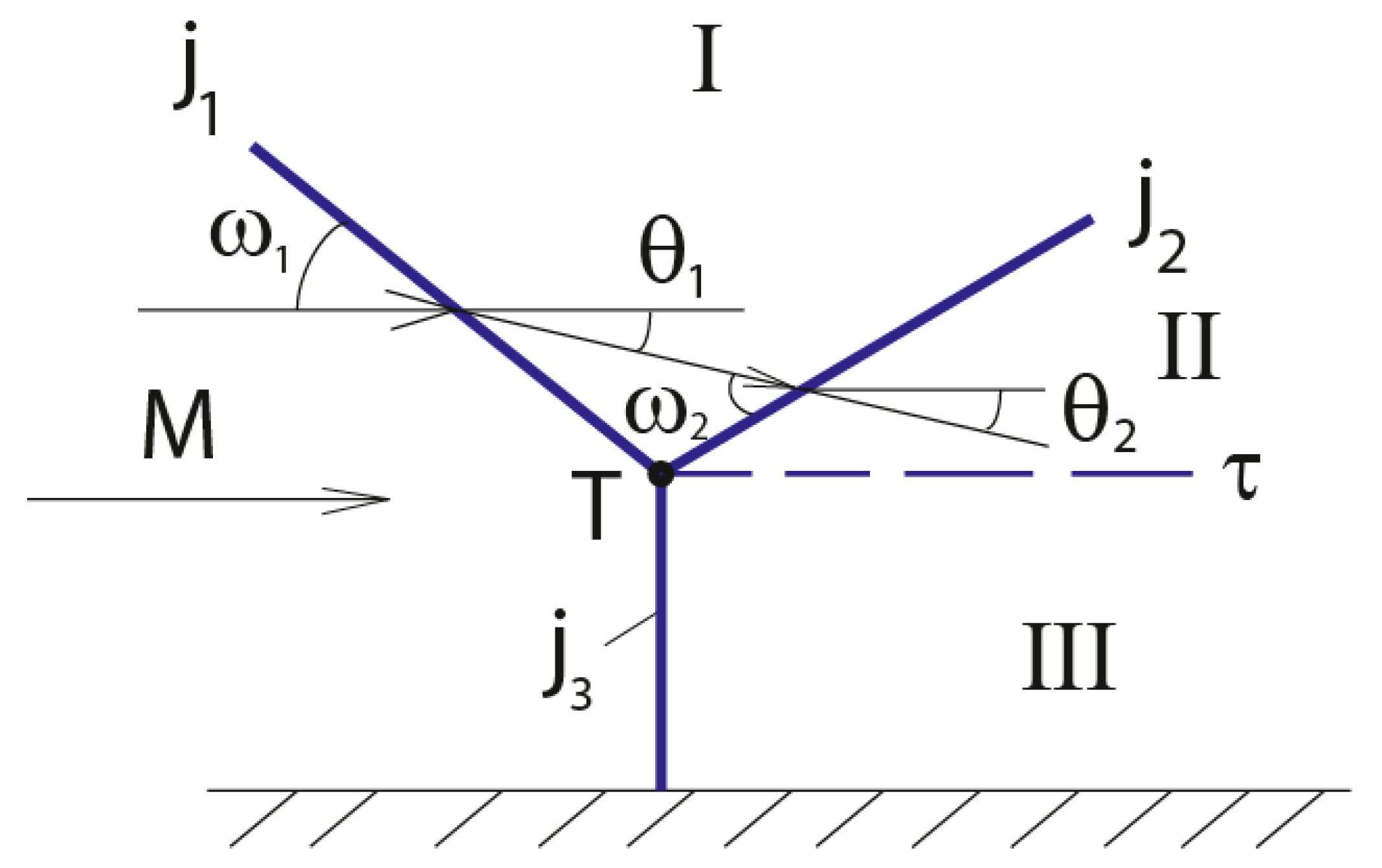
Figure 2.
Graphic solution using shock polars: (a) at (here ); (b) at (here ); (c) at (here ). Polars IIIa–IIIf correspond to pulsed energy release at the main shock equal to 15, 30, 45, 60, 75 and 90% of the maximum value ; point “ ” corresponds to this maximum value. Vertical arrows point to variation of Mach shock strength (it diminishes as pulsed energy release increases). Inclined arrows correspond to variation of strength of the incident shock forming the SMC (it decreases at , but at it initially increases and decreases only afterwards, at larger pulsed energy releases). Point l corresponds to shocks with maximum flow deflection angles, point N to von Neumann criterion, point d to the detachment criterion, and point 1s to the incident shock that forms the SMC at maximum impulse energy release.

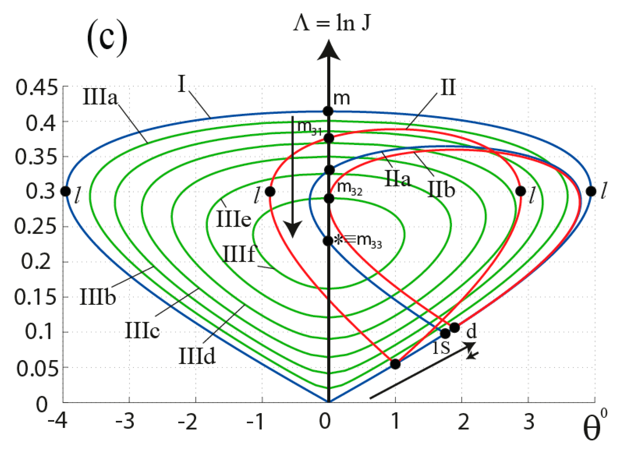
Figure 3.
Special shock strengths. Curve 1 corresponds to maximum flow defection: , curve 2 corresponds to von Neumann criterion: , curve 3 corresponds to detachment criterion: , curve 4 corresponds to normal Mach shocks without pulsed energy release: , curve 5 corresponds to maximum pulsed energy release of the main shock: , curve 6 corresponds to incident shocks forming SMCs at maximum pulsed energy release: , curve 7 corresponds to Mach shocks in SMCs with maximum incident shock strength; curve 8 corresponds to critical flow velocity after the incident shock. Curves 2a–2d and 6a–6d describe the variation of maximum and minimum shock strength at SMCs when the adiabatic index changes at the main shock. Points c1–c4 demonstrate the shift in Mach number Mb of coincidence of the reflection type criteria at adiabatic index variation.
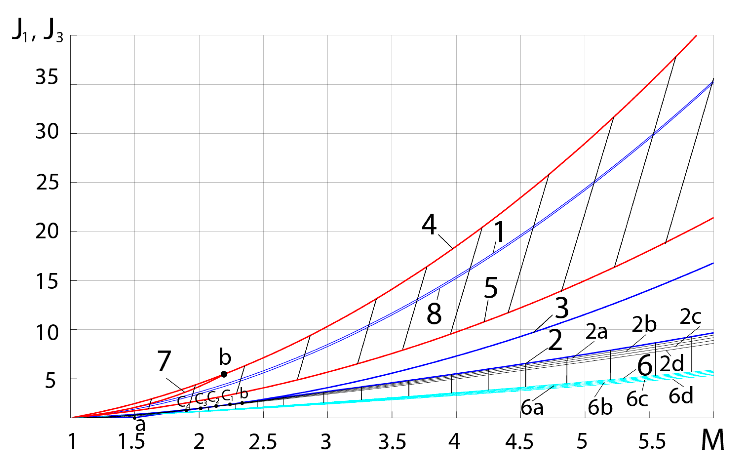
Figure 4.
Minimum (the lower branches of curves 1–5) and maximum (the upper branches) shock strengths at various Mach numbers (curves 1–5 correspond to M = 2, 3, 4, 5 and 7). Curves “” correspond to the maximum pulsed energy release and to degeneration of shock polar to a single point (see Figure 2).

Figure 5.
Flow deflection angle at special incident shocks. As in Figure 3, curve 2 corresponds to von Neumann criterion, curve 3 corresponds to detachment criterion, curve 6 corresponds to incident shocks forming SMCs at maximum pulsed energy release, and curve 8 corresponds to critical flow velocity after the incident shock. Curves 2a–d and 6a–d describe the variation of incident shock features when the adiabatic index changes at the main shock. Points c1-c4 demonstrate the shift of Mach number Mb of coincidence of the reflection type criteria.

Figure 6.
Slope angles of special incident shocks. As in Figure 3 and Figure 5, curve 2 corresponds to von Neumann criterion, curve 3 corresponds to the detachment criterion, curve 6 corresponds to incident shocks forming SMCs at maximum pulsed energy release, and curve 8 corresponds to critical flow velocity after the incident shock. Curve 9 demonstrates the Mach angles. Curves 2a–d and 6a–d describe the variation of incident shock features when the adiabatic index changes at the main shock. Points c1–c4 demonstrate the shift of Mach number Mb of coincidence of two basic reflection type criteria.

Publisher’s Note: MDPI stays neutral with regard to jurisdictional claims in published maps and institutional affiliations. |
© 2021 by the authors. Licensee MDPI, Basel, Switzerland. This article is an open access article distributed under the terms and conditions of the Creative Commons Attribution (CC BY) license (https://creativecommons.org/licenses/by/4.0/).
Share and Cite
MDPI and ACS Style
Chernyshov, M.V.; Kapralova, A.S.; Matveev, S.A.; Savelova, K.E. Stationary Mach Configurations with Pulsed Energy Release on the Normal Shock. Fluids 2021, 6, 439. https://doi.org/10.3390/fluids6120439
AMA Style
Chernyshov MV, Kapralova AS, Matveev SA, Savelova KE. Stationary Mach Configurations with Pulsed Energy Release on the Normal Shock. Fluids. 2021; 6(12):439. https://doi.org/10.3390/fluids6120439
Chicago/Turabian StyleChernyshov, Mikhail V., Anna S. Kapralova, Stanislav A. Matveev, and Karina E. Savelova. 2021. "Stationary Mach Configurations with Pulsed Energy Release on the Normal Shock" Fluids 6, no. 12: 439. https://doi.org/10.3390/fluids6120439