Cone-Beam Computed Tomography in Orthodontics

Abstract
1. Introduction
2. Radiation Dosage of CBCT in Orthodontics
3. Limitations and Liability Associated with the Use of CBCT in Orthodontics
4. Justifying the Use of CBCT in Orthodontics According to Established Guidelines
5. Benefits and Evidence-Based Indications of CBCT in Orthodontics
6. Following the ALARA and ALADAIP Principles
7. Case Series
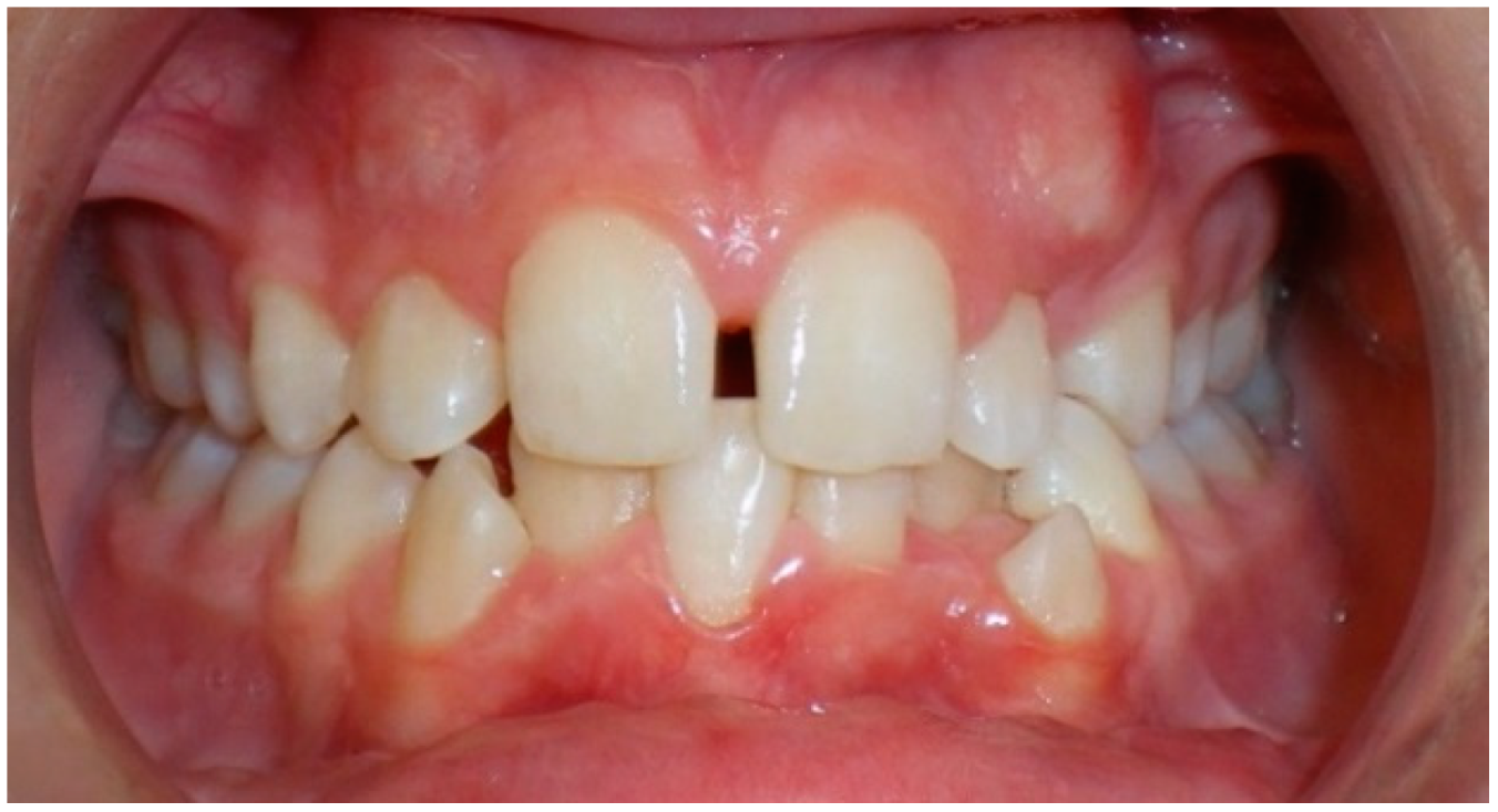
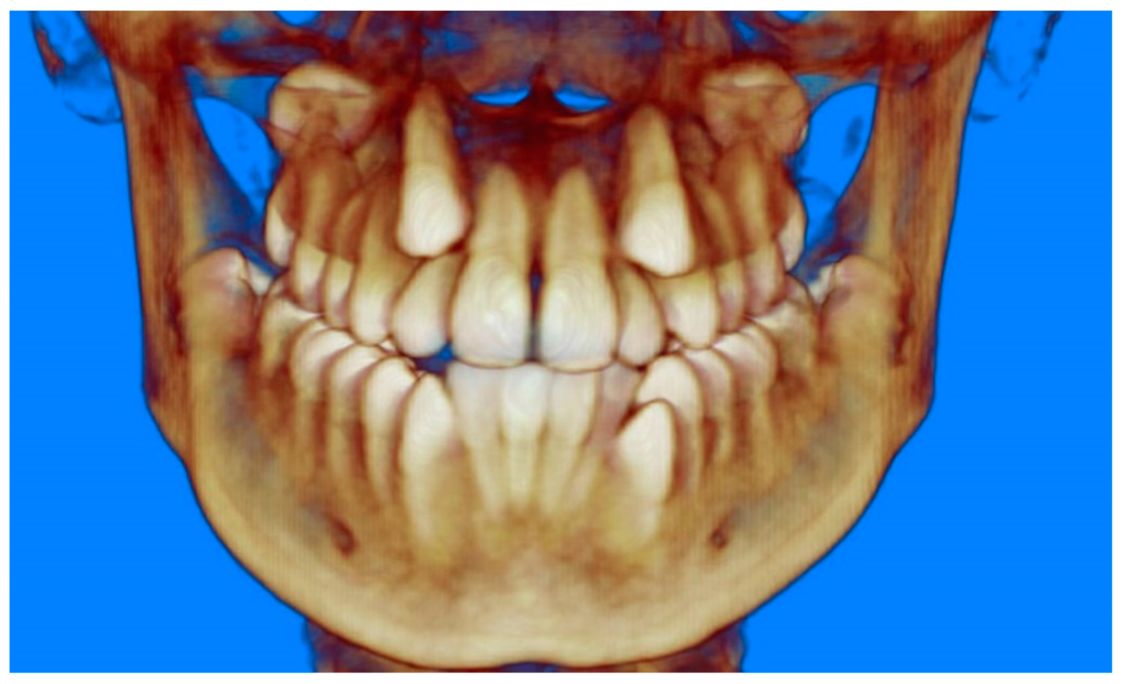
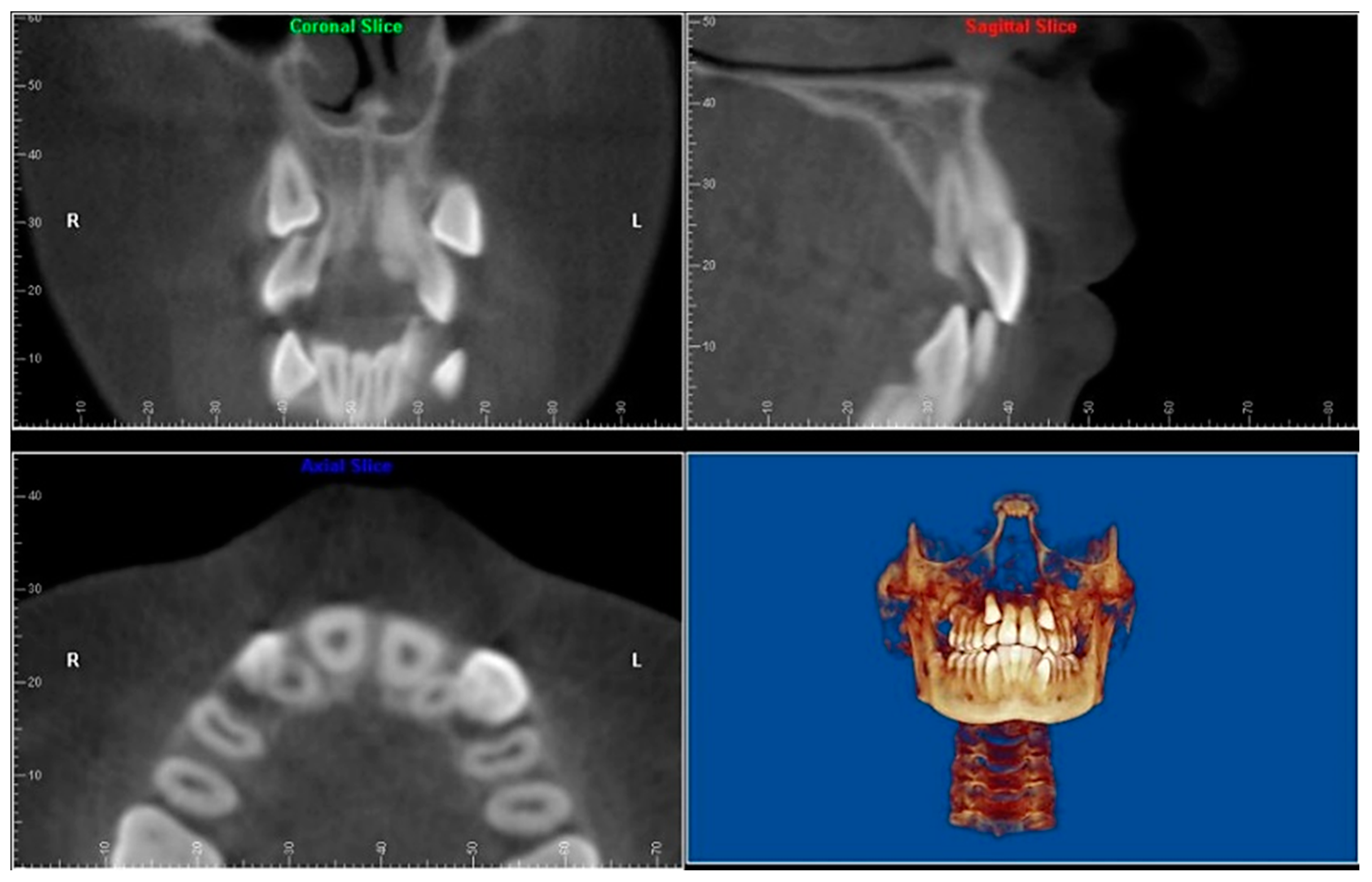
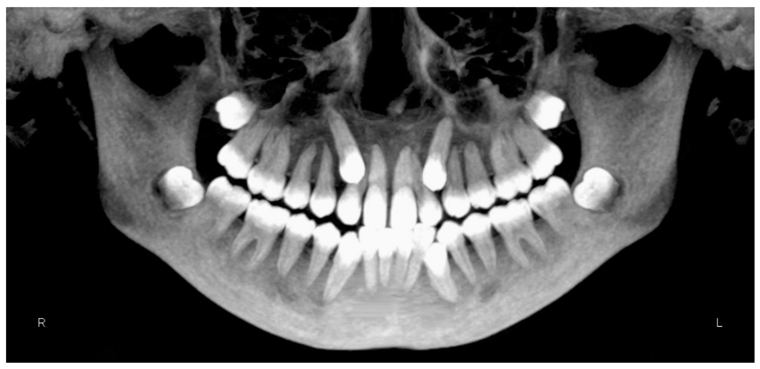
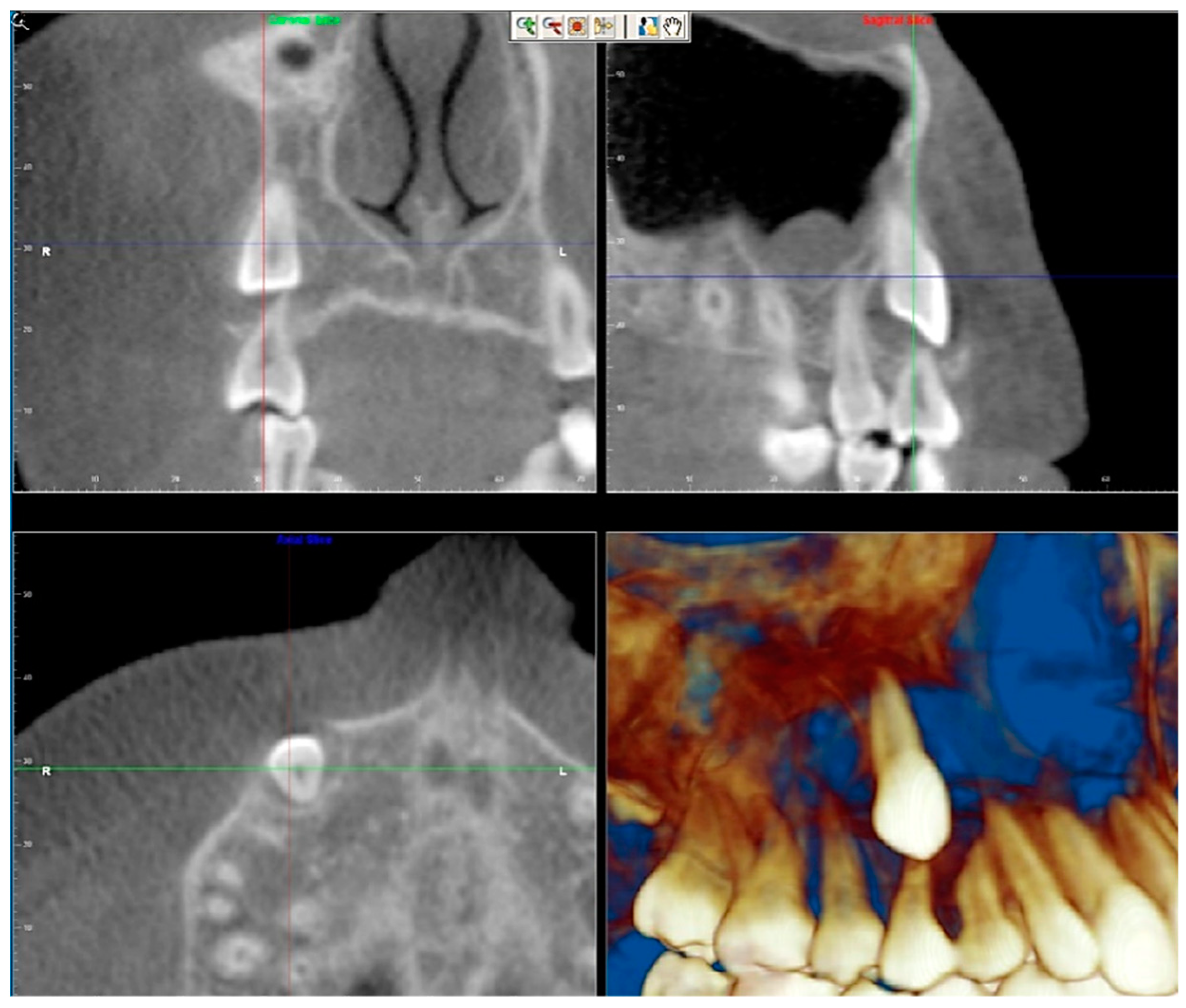
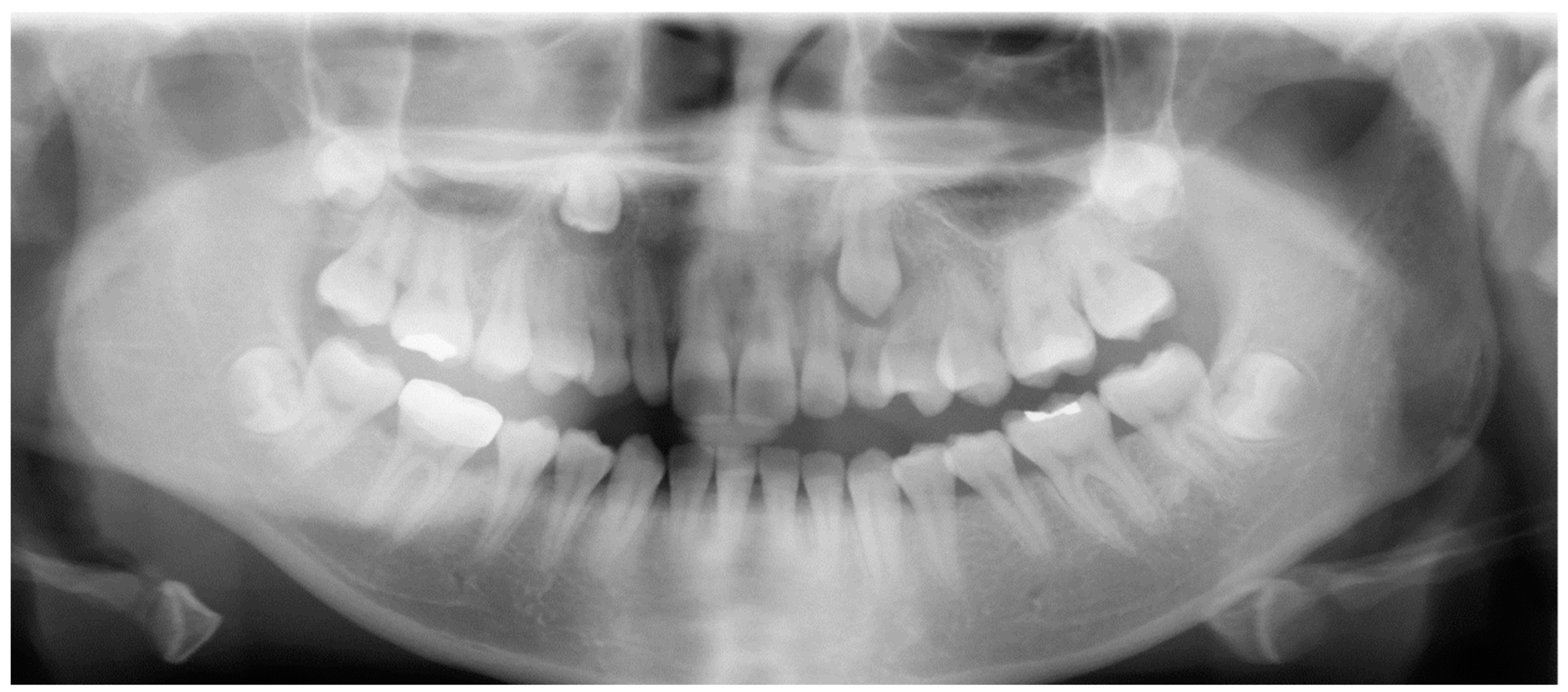
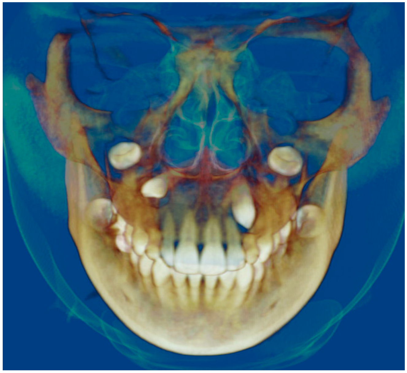
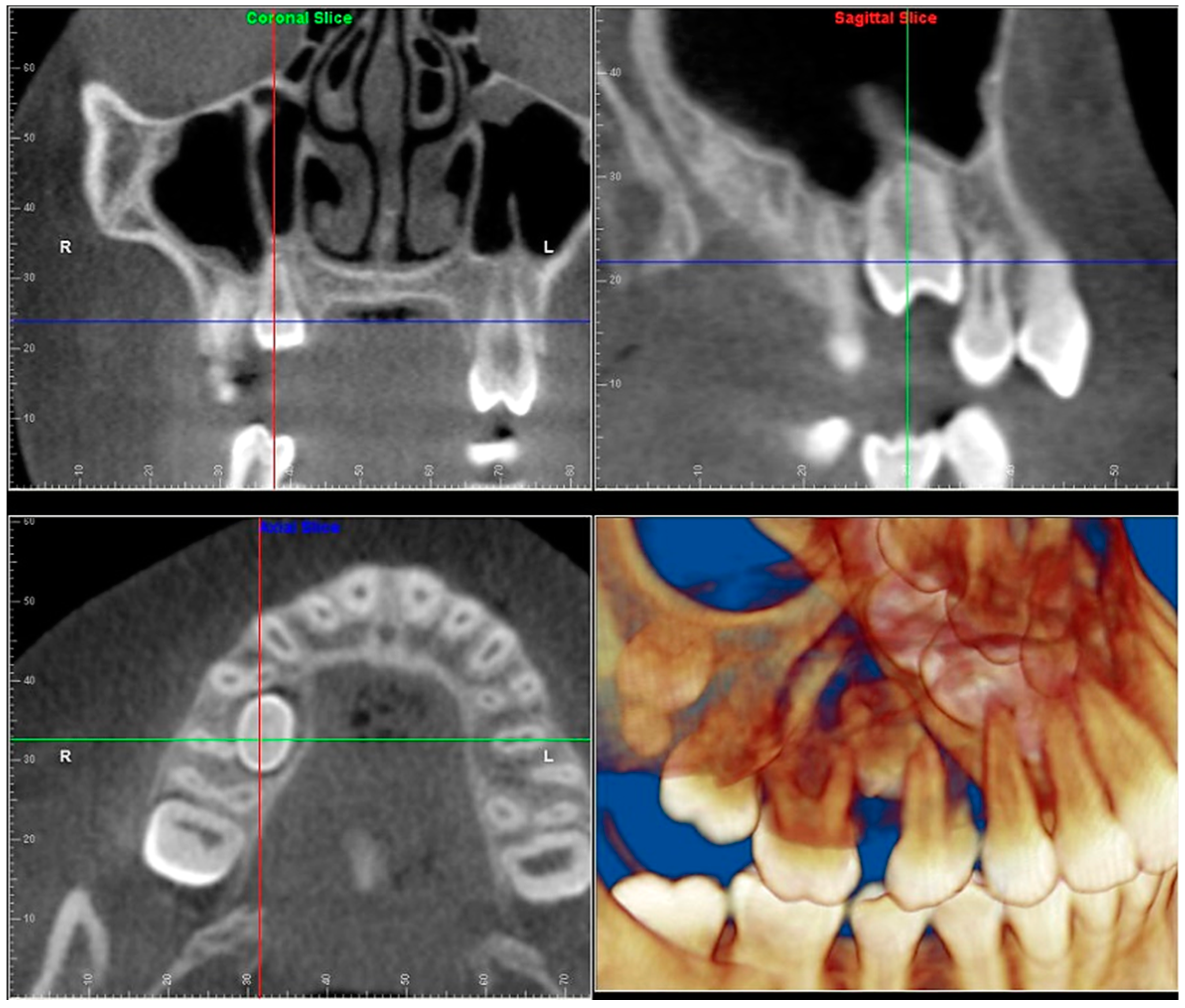
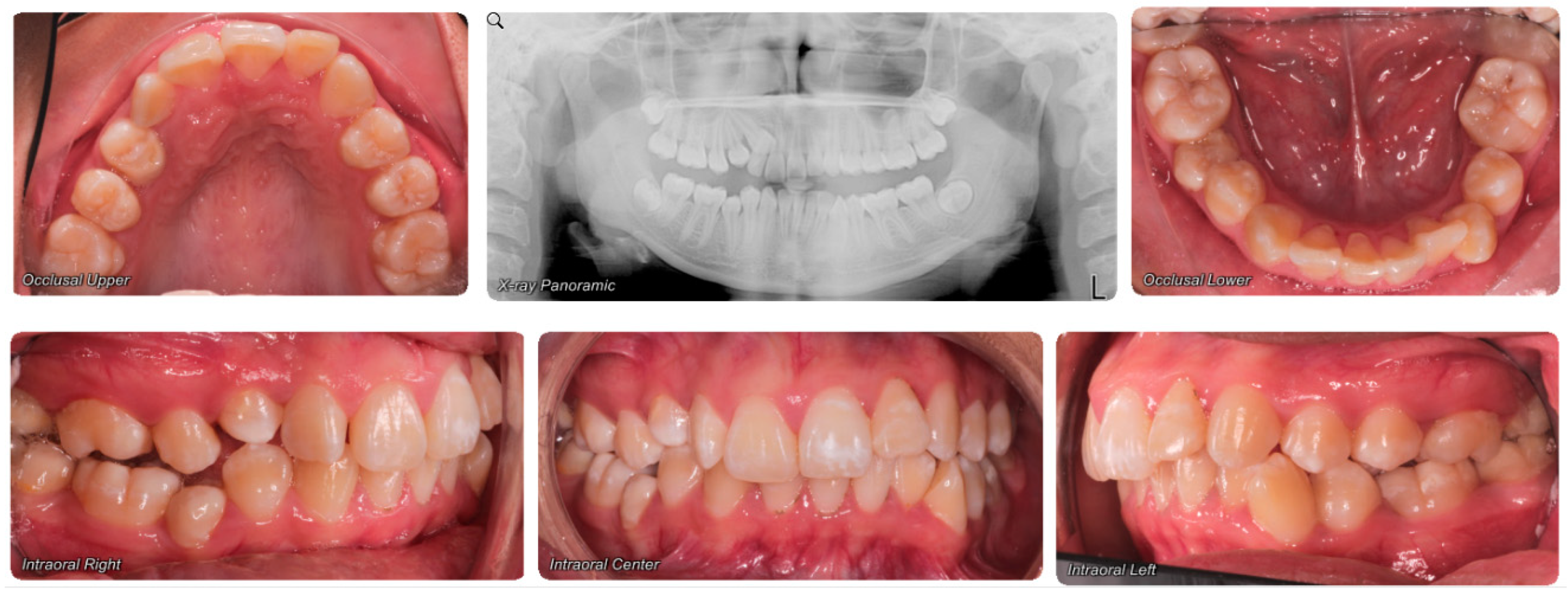
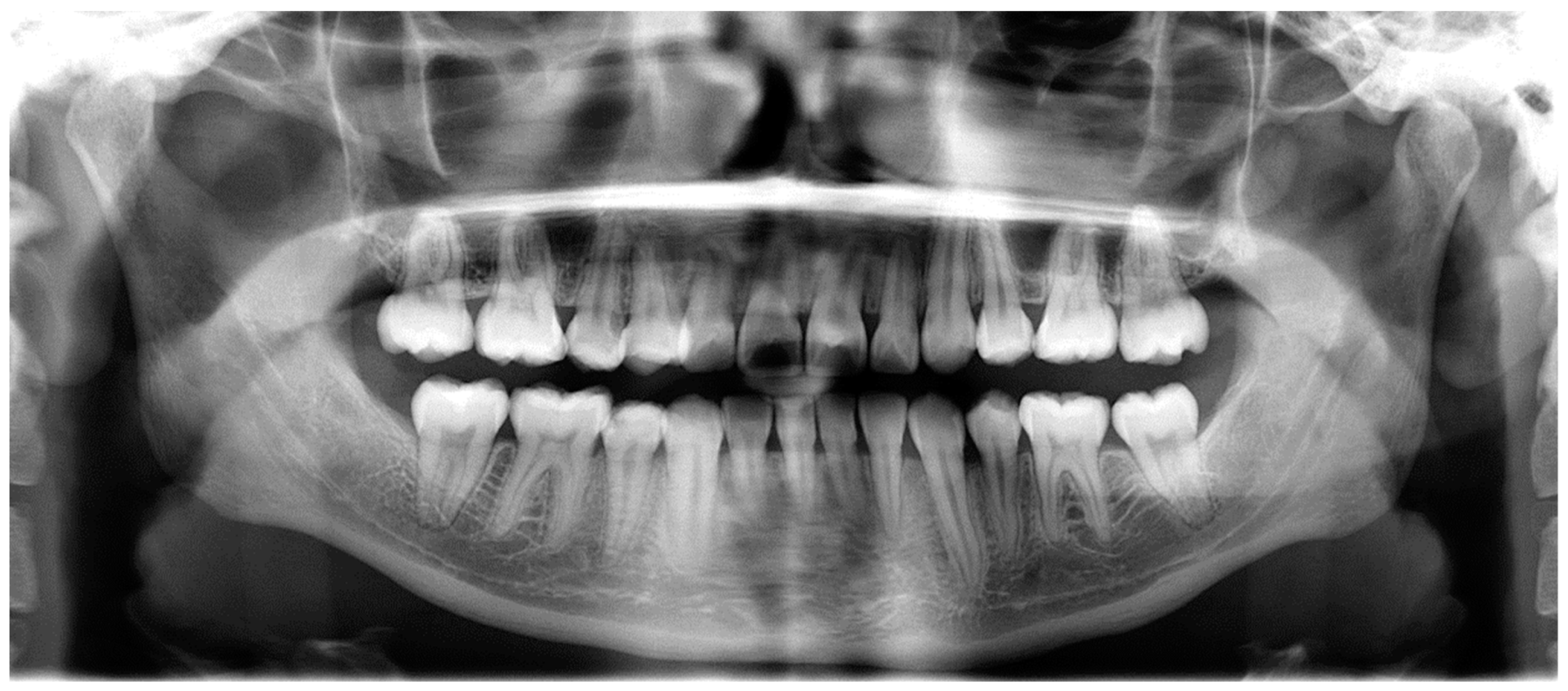
- Evaluation of impacted teeth, a common indication of CBCT in orthodontics. The advantages of CBCT include assessment of the tooth location and position, the stage of development, and status of adjacent teeth. CBCT is justified in these cases, because CBCT has the capability of evaluating the impacted teeth and adjacent structures more accurately than 2D conventional imaging. The benefit–risk ratio is favorable, especially if the CBCT volume is collimated to the impacted tooth. Figure 1, Figure 2, Figure 3 and Figure 4 show an example of impacted maxillary canines, and their proximity to the maxillary lateral incisors. Figure 1 shows an intraoral photograph. The benefit of CBCT acquisition in this case includes the ability to visualize the canines and the lateral incisors in three dimensions, which can be visualized in Figure 2 and Figure 3. In this case, the maxillary right lateral incisor exhibited external root resorption, a finding that would be difficult to see on a conventional 2D panoramic radiograph. Figure 4 shows a Maximum Intensity Projection of a panoramic view derived from the CBCT volume. This unique view is free of magnification, distortion, ghost images, and overlaps frequently seen in conventional 2D panoramic radiography.
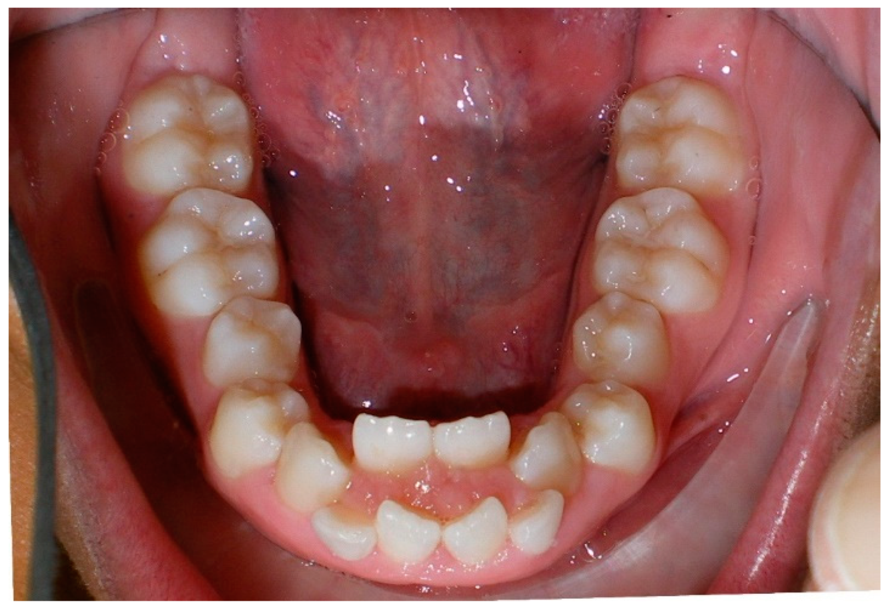
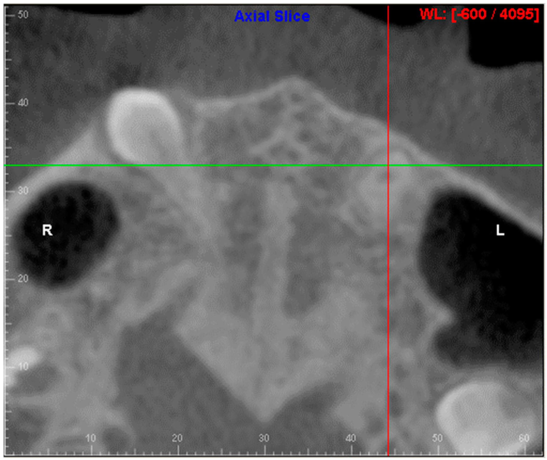
- Evaluation of buccal and lingual cortical plates: Figure 5, Figure 6 and Figure 7 show a case in which the mandibular lateral incisors are positioned lingual to the central incisors. Both mandibular lateral incisors are adjacent to each other. Figure 5 shows and intraoral occlusal photos with retained deciduous mandibular lateral incisors. There was no way to evaluate the buccal and lingual cortical plates through conventional 2D panoramic, periapical or occlusal radiographs. Therefore, CBCT was acquired and collimated to the area of teeth in order to assess the relationship of the four mandibular incisors to the labial and lingual cortical plates as well as to the adjacent teeth. As Figure 6 and Figure 7 display, CBCT shows that all permanent mandibular incisors are sound. It is important to note that thin buccal and lingual cortical plates may not be seen via CBCT—this does not denote that they are not present. In other words, CBCT images may not show a clinically present thin buccal and lingual cortical plates. In this case, the diagnostic information obtained from CBCT is far more significant than the information obtained from any other radiographic imaging technique.
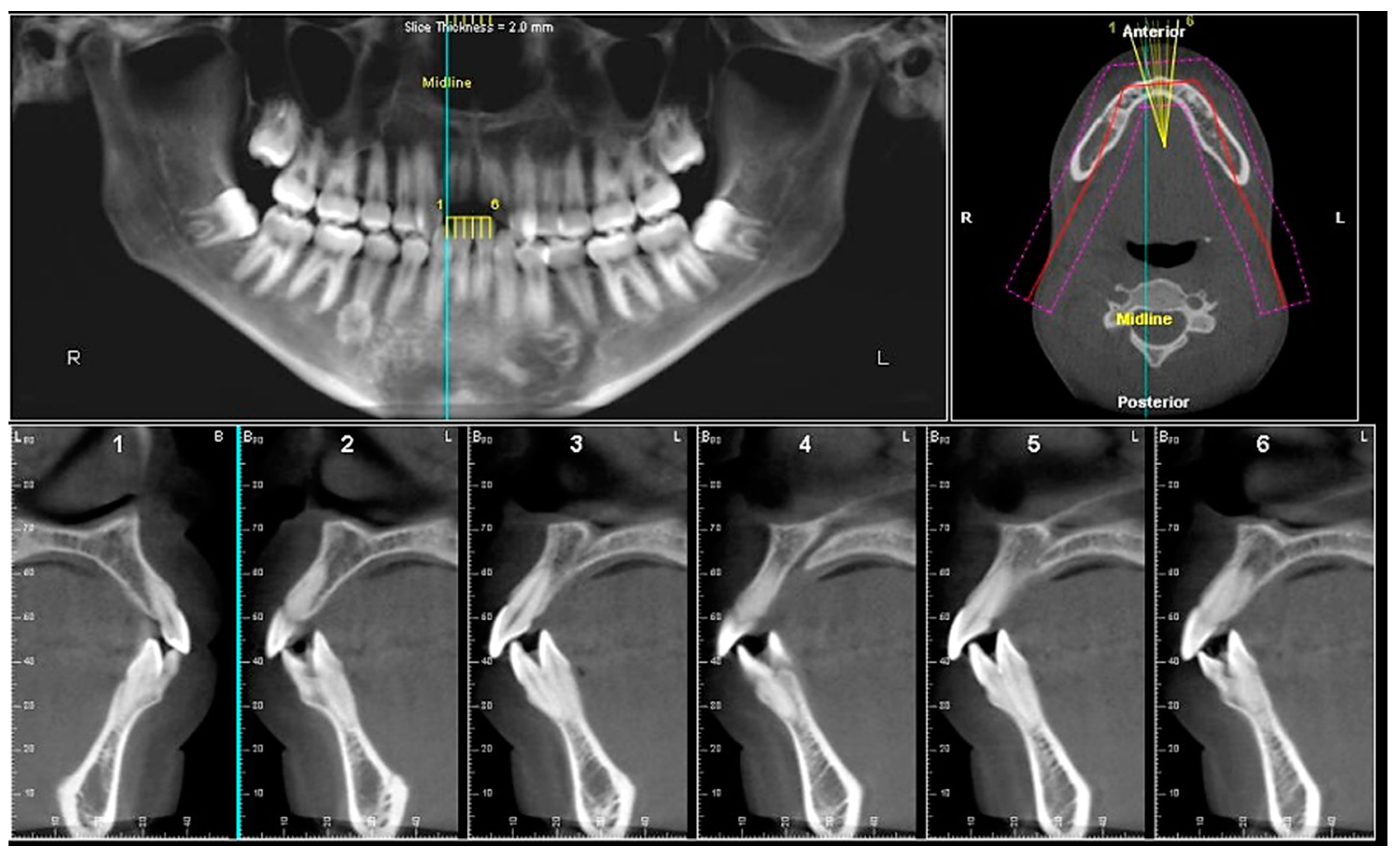
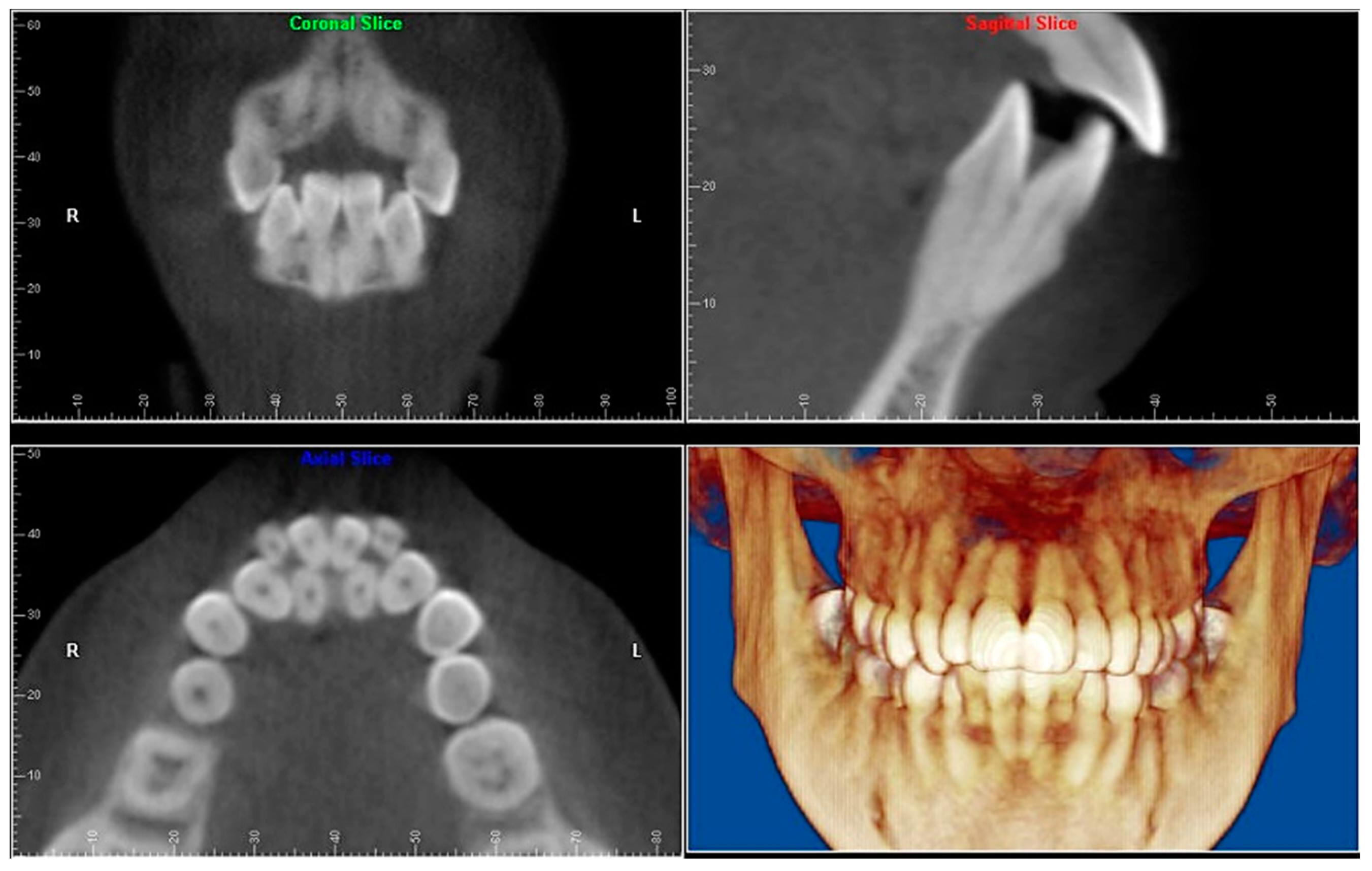
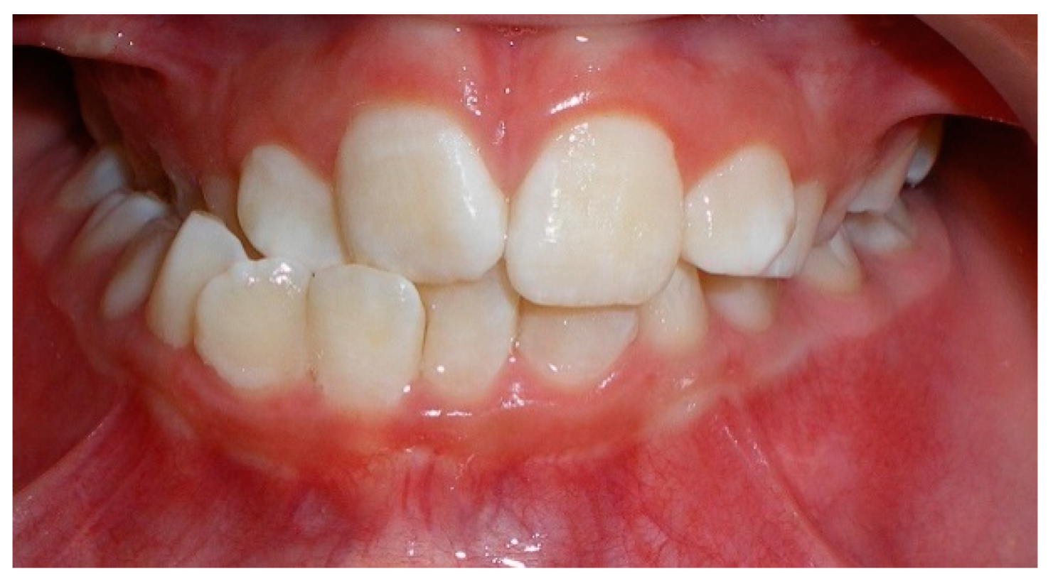
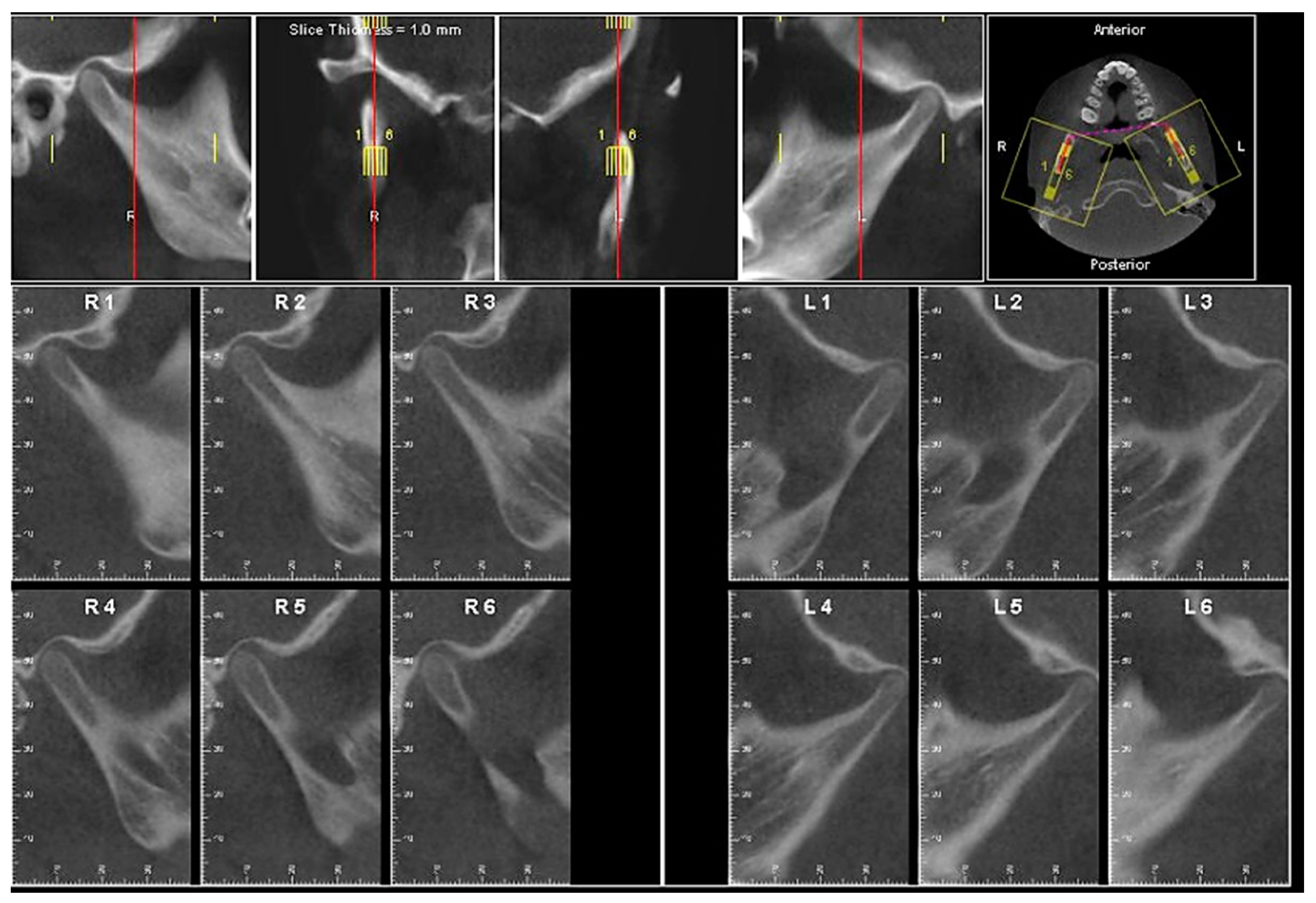
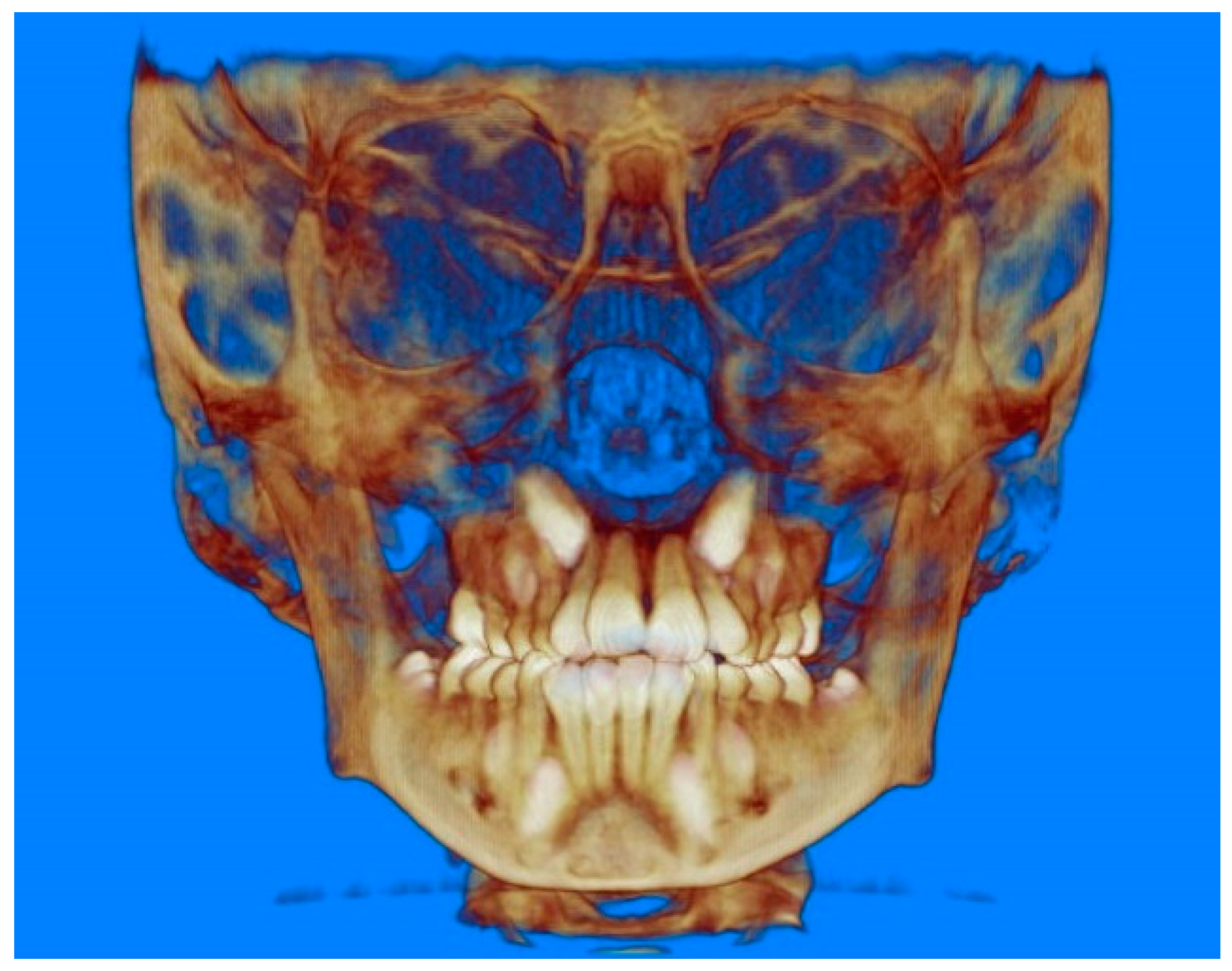
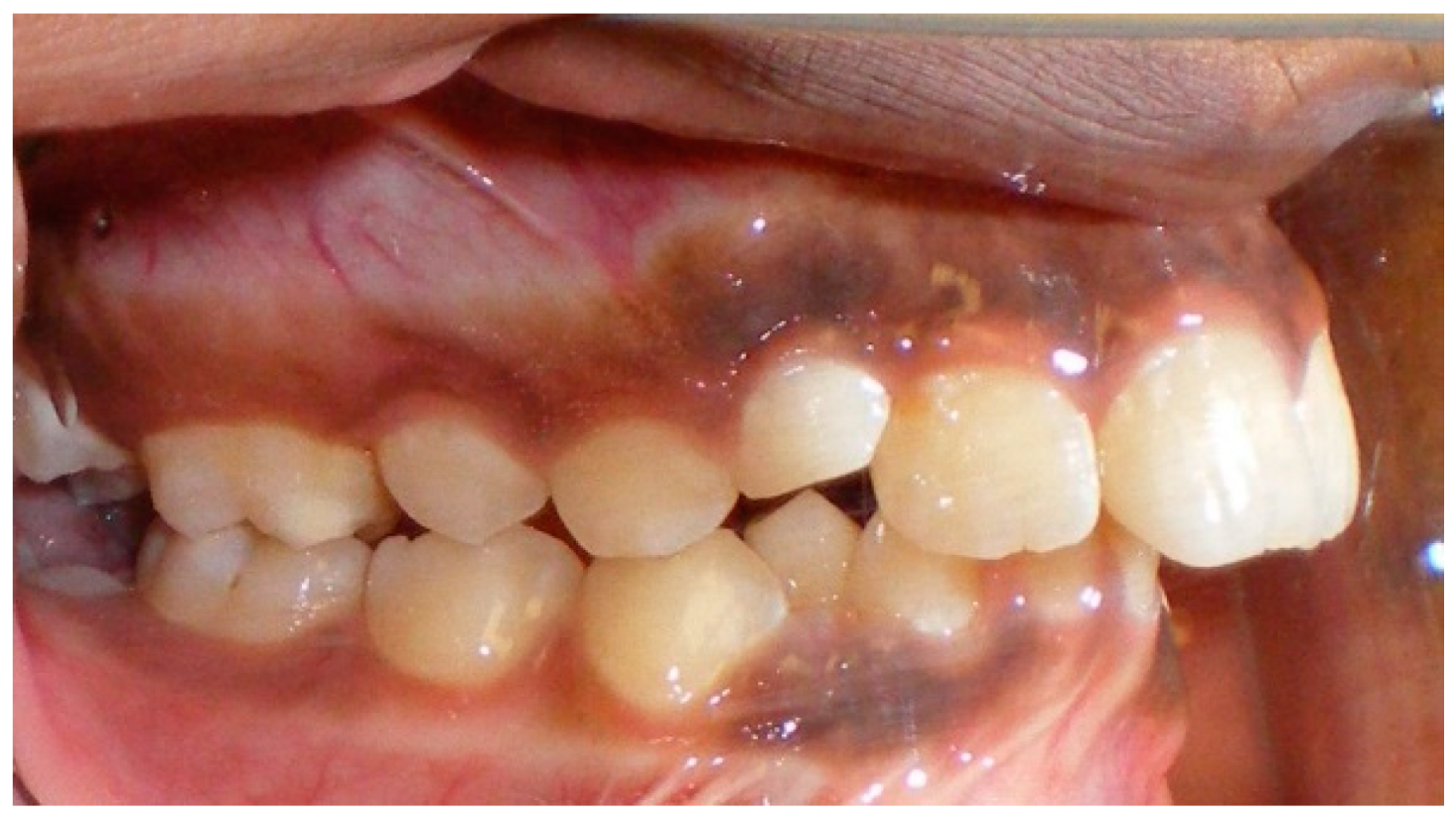
- TMJ and facial asymmetry evaluation. Figure 8, Figure 9 and Figure 10 show a case in which a whole head CBCT was acquired initially due to the presence of facial asymmetry and history of temporomandibular disorders. Figure 8 shows an intraoral photograph with a unilateral posterior crossbite on the right side, a mandibular midline shift to the right side, and an anterior crossbite on the right lateral incisors. Figure 9 shows cross-sectional views of the TMJ, with a very mild flattening of the joints. Figure 10 shows volume rendering of the CBCT volume, demonstrating lack of symmetry of the face, unilateral posterior crossbite observed on the right side involving premolars and molars, and ectopic canines. The benefits of CBCT imaging in this case are the evaluation the TMJ, visualization of the crossbite on the right side via the volume rendering view, and the ability to perform any isometric measurements, if needed.
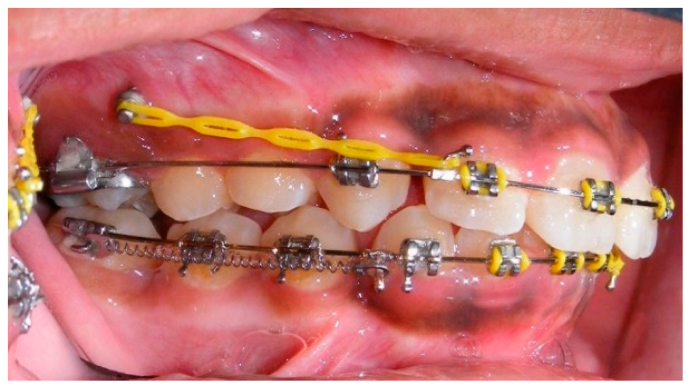
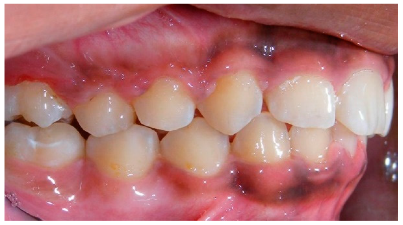
- Assessment of proposed sites of temporary anchorage device (TAD). Figure 11, Figure 12, Figure 13 and Figure 14 show correction of the Class II molar relationship using a temporary anchorage device. Figure 11 shows a pre-treatment intraoral photograph of the right side. The Class II molar relationship can be observed. Figure 12 shows coronal, sagittal and axial views, as well as a volume rendering of CBCT that was acquired in order to assess the site of the temporary anchorage device. Figure 13 shows an intraoral photograph of the right side, in which the TAD was placed mesial to the maxillary first molar, and a power chain was attached from this TAD to a hook placed distal to the lateral incisor. Figure 14 shows a post-treatment intraoral photograph showing improvement of the Class II molar relationship after removal of all orthodontic appliances.
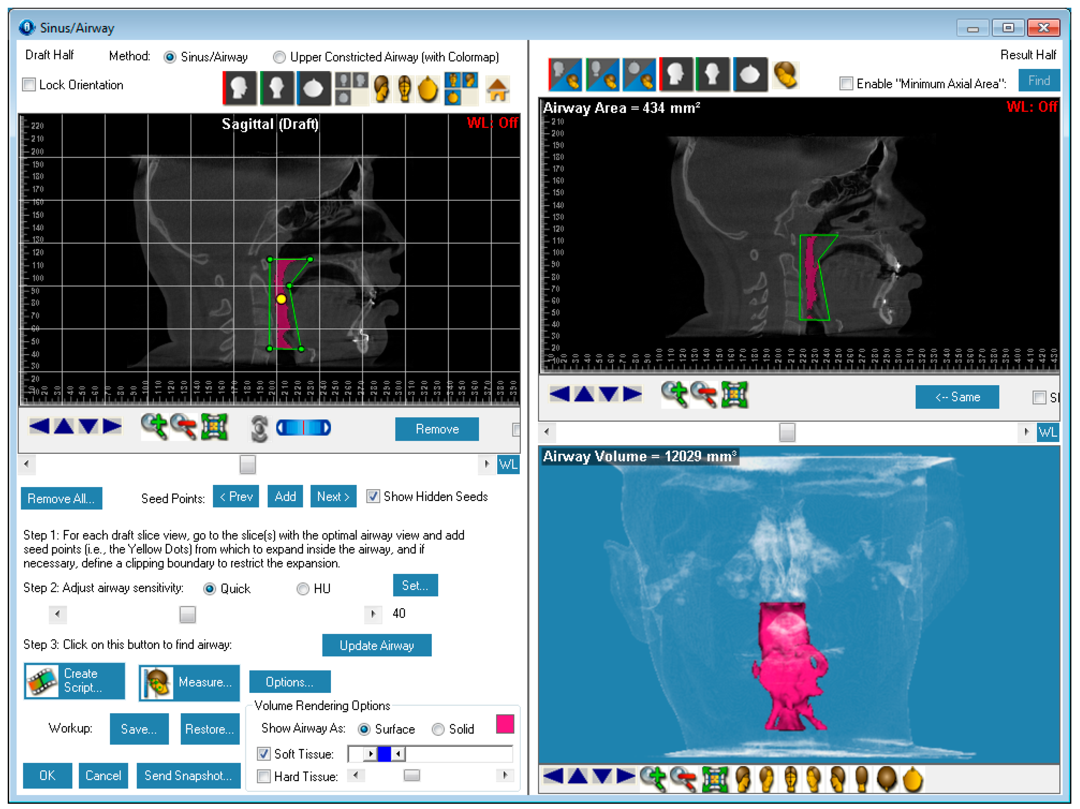
- Oropharyngeal airway assessment. In the past, airway assessment was made using conventional 2D cephalometric radiographs. However, the airway is a three-dimensional structure; it is thus best imaged by a three-dimensional imaging technique. The benefit of CBCT in airway studies is the ability to measure the volume size and evaluate the airway in three dimensions. This is valuable for diagnosis and treatment planning in several cases, especially orthognathic surgery cases. Using CBCT volume, it is possible to measure oropharyngeal airway volume and area. Figure 15 shows a measurement of oropharyngeal airway volume and area via Dolphin 3D Imaging software version 11.95 (Dolphin Imaging and Management Solutions, Chatsworth, CA, USA).
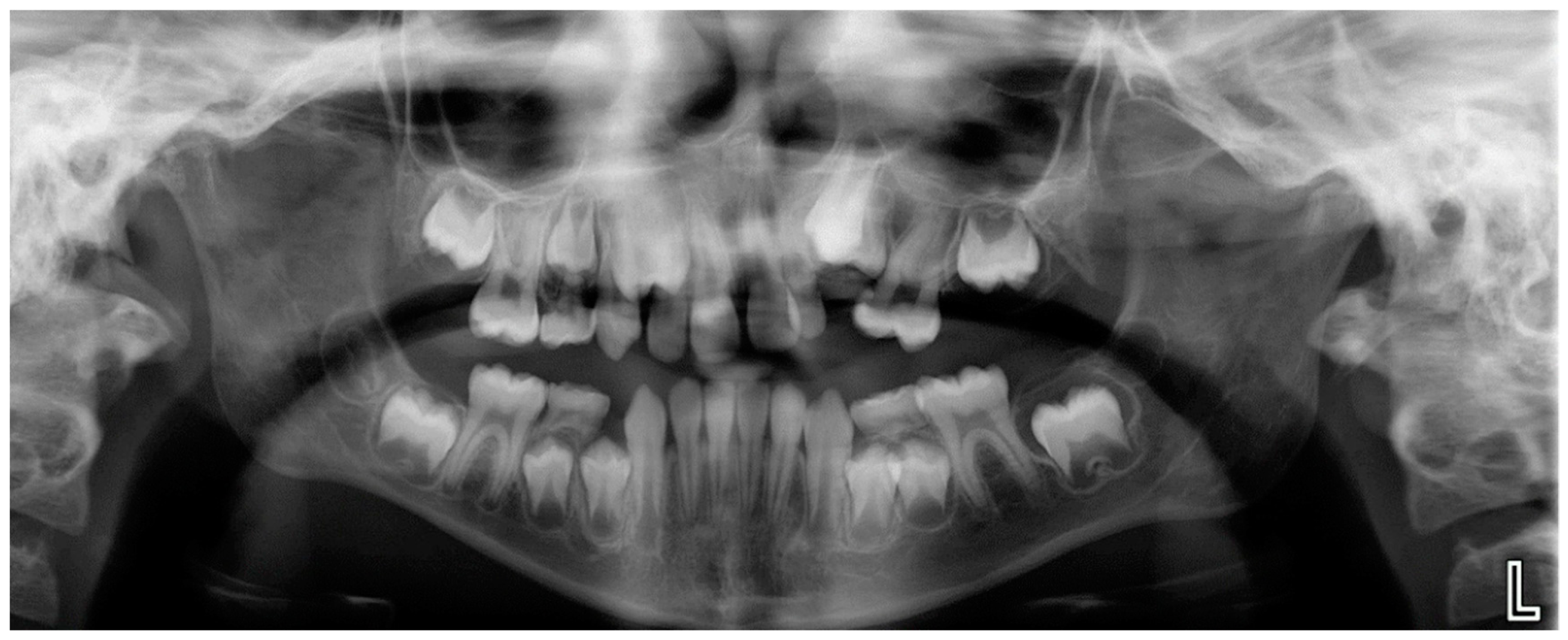
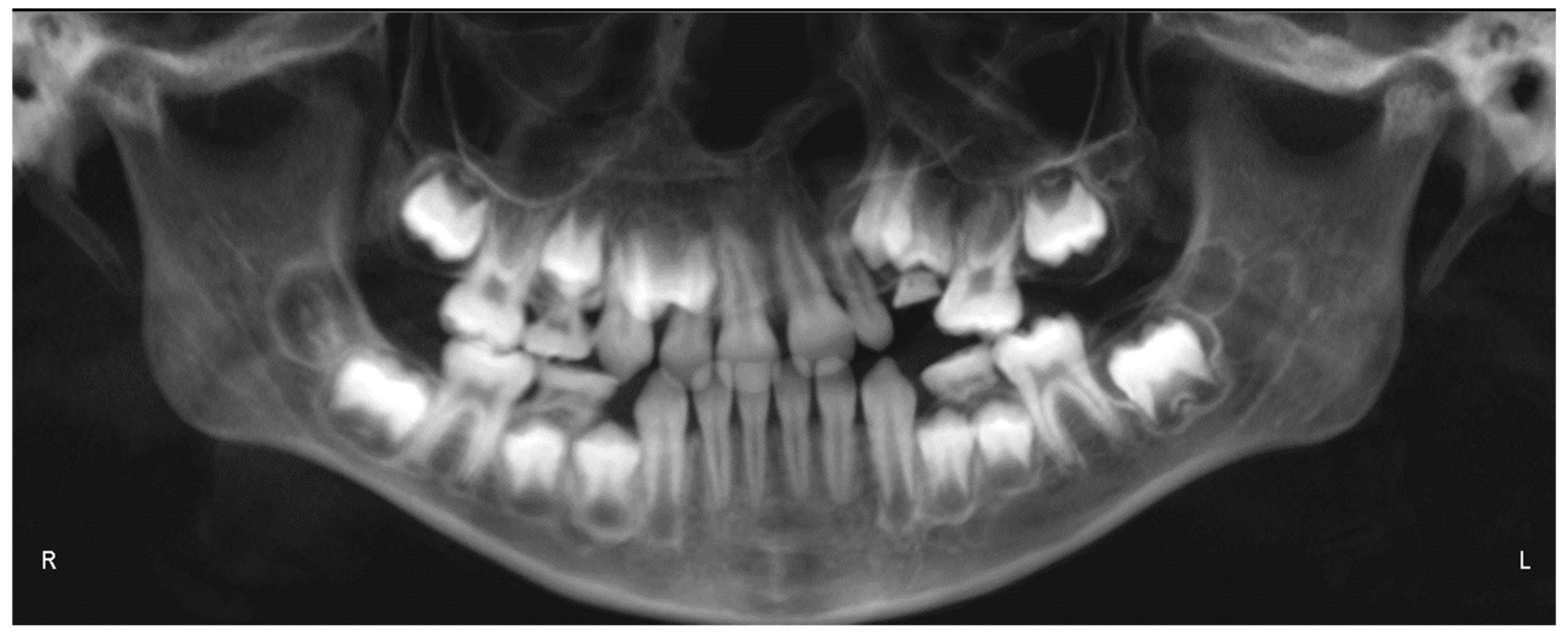
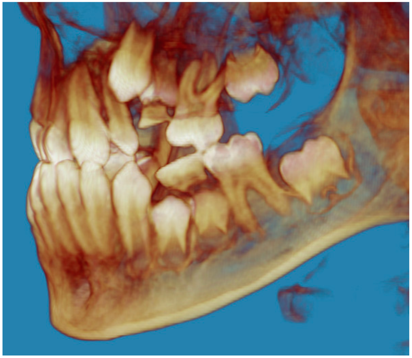
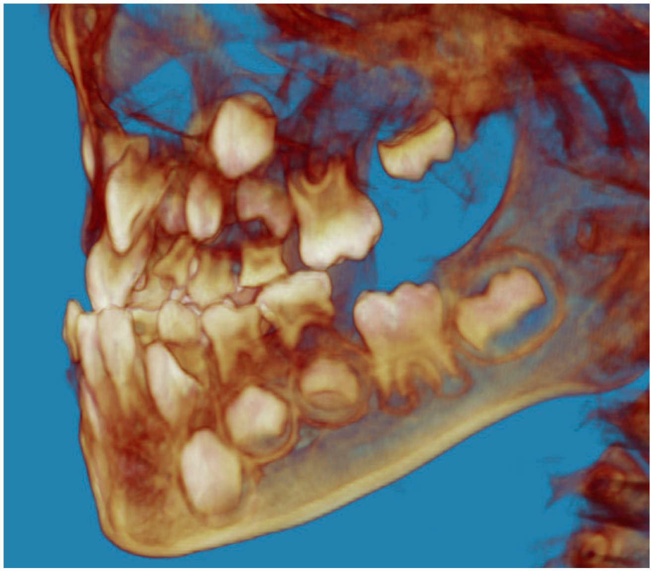
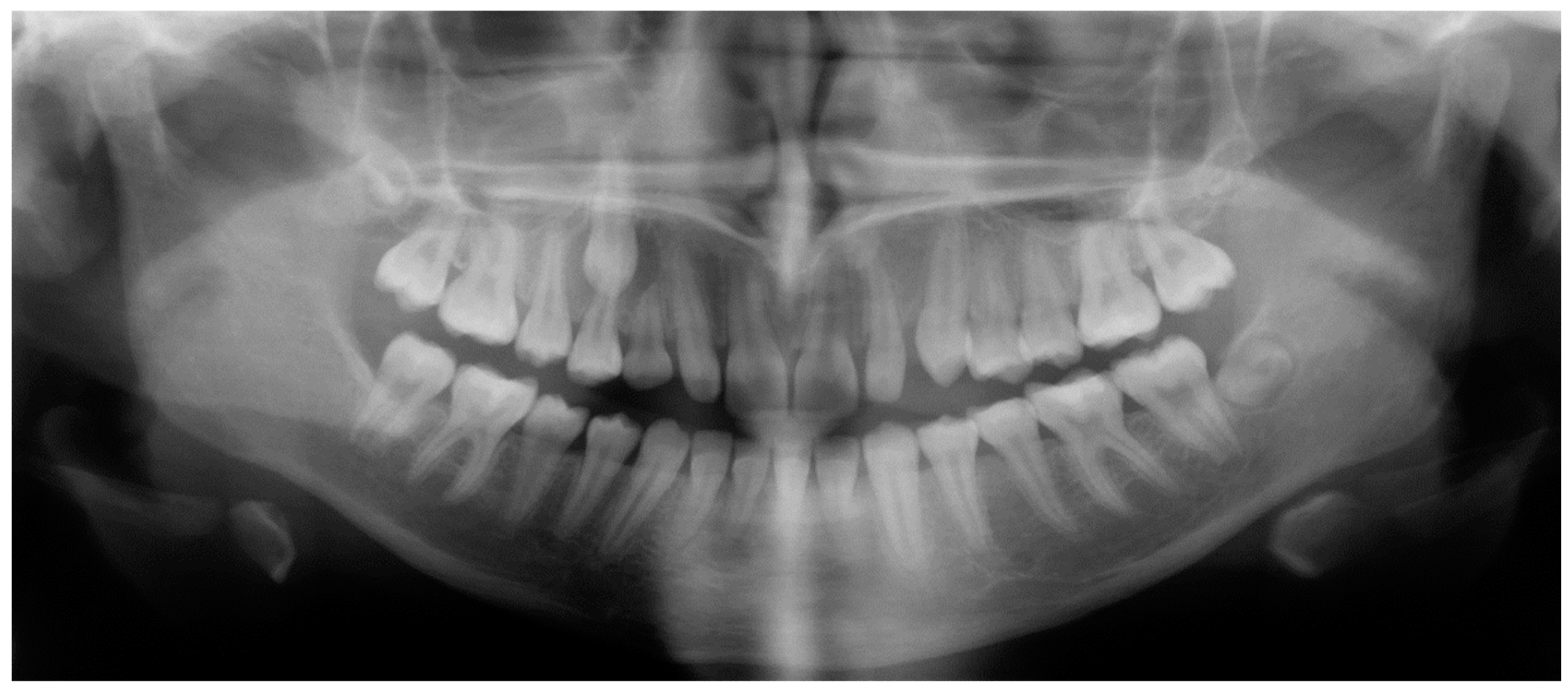
- Assessment of an ankylosed and submerged primary tooth. Due to limitations of panoramic radiography, objects located outside of the focal trough may not be well visualized. In addition, it may be difficult in some cases to visualize objects that are located within the focal trough. Figure 16 presents an example of a conventional 2D panoramic radiograph in which it was impossible to visualize an ankylosed and submerged primary maxillary left second molar for a child who was 11 years of age. There are two findings that can be seen on the conventional panoramic radiograph: a transposition between the maxillary right canine and first premolar, and a missing maxillary left first premolar. However, the impacted primary molar in the upper left quadrant is not depicted on the conventional panoramic radiograph in Figure 16. After acquisition of CBCT, which was made on the same day the 2D panoramic radiograph was taken, it was possible to see the primary tooth. Figure 17 shows a panoramic view derived from the CBCT volume which shows the ankylosed and submerged primary maxillary left second molar. This tooth can also be seen in the CBCT volume rendering in Figure 18. Interestingly, the patient had another CBCT scan taken approximately three years earlier when the child was 8 years of age. The earlier scan explained the etiology for the problems in the upper left quadrant. The earlier CBCT, displayed in Figure 19, shows that the primary maxillary left second molar was fully erupted and present in the mouth. After the primary tooth became ankylosed, it gradually became severely infraoccluded and then became completely submerged. Meanwhile, the adjacent permanent maxillary left first molar drifted mesially due to lack of space mesial to the tooth, and at the same time the ankylosed primary molar obstructed the eruption of its succedaneous premolar.
- Assessment of an impacted maxillary canine located superior to a first premolar. Occasionally, transposed or impacted teeth are seen in unusual positions which require accurate diagnosis and treatment planning. Figure 20 presents a 2D conventional panoramic radiograph in which the permanent maxillary right canine can be seen in an unusual position. CBCT was prescribed in order to assess the location of the canine, its relationship to adjacent structures, and the status of the first premolar root. Figure 21 shows CBCT views of the impacted canine and its close proximity to the root of the first premolar. In addition, external root resorption on the first premolar can be visualized. An oral and maxillofacial pathologist evaluated the pericoronal radiolucency adjacent to the crown of the canine, ruled out cystic transformation, and confirmed that it was a hyperplastic follicle. Because the apex of the canine is distal to the apex of the first premolar, coupled with the unusual position of the canine, the orthodontist decided in this case to first extract the primary maxillary right canine, mesially move the maxillary right first premolar to the site of the canine, and then simply extrude the canine via orthodontic traction and place it in the site of the first premolar.
- Assessment of a horizontally impacted maxillary canine. Figure 22, Figure 23 and Figure 24 show a case in which the permanent maxillary right canine was impacted in a horizontal position. As Figure 22 shows, the conventional 2D panoramic radiograph does not depict the accurate position of the maxillary right canine. On the other hand, it shows some information about the location and status of development of the permanent maxillary left canine. For instance, extraction of the primary maxillary left canine could be followed by orthodontic traction of the succedaneous tooth. However, this would not be realistic for the right canine. As Figure 23 and Figure 24 show, the right canine is impacted in a horizontal position. The apex of this canine is in close proximity to the right nasal fossa. An attempt to bring this tooth into alignment would carry significant risks. For example, the tooth may be ankylosed, its movement may damage adjacent teeth or structures, it may become devitalized or infected, and most importantly, it can result in a significantly prolonged orthodontic treatment. Orthodontic movement of this canine would likely be ruled out by most orthodontists. The patient’s parents can either choose to extract this tooth or monitor it long term. A referral to an oral and maxillofacial surgeon can be valuable in order to discuss options for management of this impacted tooth. The CBCT volume can be of significant value for the oral and maxillofacial surgeon for locating and evaluating the tooth accurately, after which the surgeon can present to the patient’s parents the risks and benefits of extracting the tooth versus leaving it and monitoring its status long term.
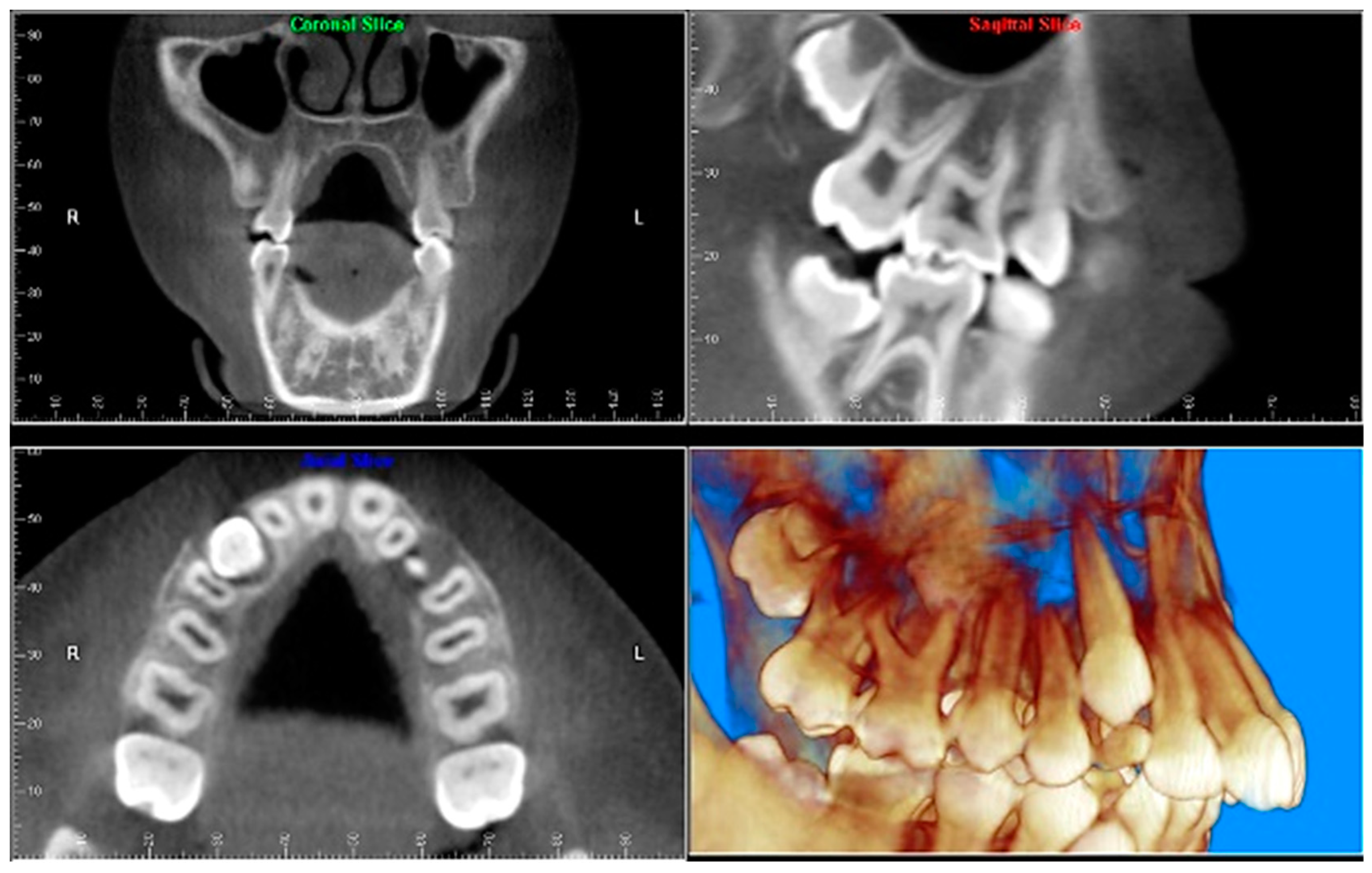
- Assessment of an impacted maxillary premolar. Figure 25 and Figure 26 show a case in which the permanent maxillary right second premolar was rotated and impacted in an unusual position. As Figure 25 shows, it is impossible to accurately evaluate the position of the impacted premolar from the conventional 2D panoramic radiograph. Three-dimensional evaluation of the impacted tooth is necessary. To visualize the tooth in three dimensions, CBCT was acquired. Figure 26 shows a coronal, sagittal, and axial views of the impacted premolar, as well as a volume rending. It can be noted that the impacted premolar is rotated in a pattern in which the buccal cusp is in the vicinity of the first premolar and the lingual cusp is in the vicinity of the first molar. In addition, the impacted tooth is in a palatal position. The orthodontic treatment plan included leveling and aligning, followed by opening space for this tooth and then bringing it to the dental arch via orthodontic traction. CBCT images provided in Figure 26 are valuable for orthodontic diagnosis and treatment plan, and would also be valuable for the surgeon who will perform the surgical exposure of the tooth and bonding of a gold chain which will be used to extrude the impacted premolar.
- Assessment of an impacted canine with close proximity to the lateral incisor. Figure 27 shows photographs and a panoramic radiograph of a case in which there is an impacted permanent maxillary right canine in an unfavorable position, a missing mandibular left second premolar and uncoordinated dental midlines. The relationship of the impacted canine to the adjacent lateral incisor cannot be determined from the conventional 2D radiograph. Therefore, CBCT was acquired. Figure 28 shows CBCT images, including coronal, sagittal, axial views, and volume rendering, which demonstrated close proximity of the impacted canine to the lateral incisor, and an area of bone loss buccal to the crown of the impacted canine. Before acquisition of CBCT, the tentative treatment plan was to extract the maxillary right first premolar and bring the canine to the dental arch. However, due to the findings presented by CBCT, the treatment plan was altered in favor of extracting the impacted canine, a clinical decision that was strongly favored by the patient. In this case, the first premolar would substitute for the canine. The maxillary left first premolar and mandibular right first premolar were also extracted. Therefore, each quadrant would have one missing tooth by end of treatment. Orthodontic post-treatment photographs are presented in Figure 29. Figure 30 shows a post-treatment 2D panoramic radiograph. CBCT was neither necessary nor indicated at completion of orthodontic treatment, and therefore only a conventional 2D panoramic radiograph was taken.
8. Conclusions
Funding
Conflicts of Interest
Abbreviations
| CBCT | cone-beam computed tomography |
| FOV | field of view |
| µSv | microSieverts |
| TMJ | temporomandibular joint |
References
- De Vos, W.; Casselman, J.; Swennen, G.R. Cone-beam computerized tomography (CBCT) imaging of the oral and maxillofacial region: A systematic review of the literature. Int. J. Oral Maxillofac. Surg. 2009, 38, 609–625. [Google Scholar] [CrossRef] [PubMed]
- Leonardi, R. Cone-beam computed tomography and three-dimensional orthodontics. Where we are and future perspectives. J. Orthod. 2019, 46, 45–48. [Google Scholar] [CrossRef] [PubMed]
- Hall, E.; Giaccia, A. Radiobiology for the Radiologist, 6th ed.; Lippincott Williams and Wilkins: Philadelphia, PA, USA, 2006; pp. 135–153. [Google Scholar]
- Buttke, T.M.; Proffit, W.R. Referring adult patients for orthodontic treatment. J. Am. Dent. Assoc. 1999, 130, 73–79. [Google Scholar] [CrossRef] [PubMed]
- Kleinerman, R.A. Cancer risks following diagnostic and therapeutic radiation exposure in children. Pediatr. Radiol. 2006, 36 (Suppl. 2), 121–125. [Google Scholar] [CrossRef]
- Applegate, K.E.; Thomas, K. Pediatric CT—The challenge of dose records. Pediatr. Radiol. 2011, 41 (Suppl. 2), 523–527. [Google Scholar] [CrossRef]
- Bulas, D.I.; Goske, M.J.; Applegate, K.E.; Wood, B.P. Image Gently: Why we should talk to parents about CT in children. Am. J. Roentgenol. 2009, 192, 1176–1178. [Google Scholar] [CrossRef]
- Brenner, D.J. Estimating cancer risks from pediatric CT: Going from the qualitative to the quantitative. Pediatr. Radiol. 2002, 32, 228–221; discussion 242–244. [Google Scholar] [CrossRef]
- Chodick, G.; Ronckers, C.M.; Shalev, V.; Ron, E. Excess lifetime cancer mortality risk attributable to radiation exposure from computed tomography examinations in children. Isr. Med. Assoc. J. IMAJ 2007, 9, 584–587. [Google Scholar]
- Isaacson, K.G.; Thom, A.R.; Atack, N.E.; Horner, K.; Whaites, E. Orthodontic Radiographs: Guidelines for the Use of Radiographs in Clinical Orthodontics, 4th ed.; British Orthodontic Society: London, UK, 2015. [Google Scholar]
- Applegate, K.E.; Cost, N.G. Image Gently: A campaign to reduce children’s and adolescents’ risk for cancer during adulthood. J. Adolesc. Health 2013, 52, S93–S97. [Google Scholar] [CrossRef]
- Farman, A.G. ALARA still applies. Oral Surg. Oral Med. Oral Pathol. Oral Radiol. Endod. 2005, 100, 395–397. [Google Scholar] [CrossRef]
- Brenner, D.; Elliston, C.; Hall, E.; Berdon, W. Estimated risks of radiation-induced fatal cancer from pediatric CT. Am. J. Roentgenol. 2001, 176, 289–296. [Google Scholar] [CrossRef] [PubMed]
- Slovis, T.L. Children, computed tomography radiation dose, and the As Low As Reasonably Achievable (ALARA) concept. Pediatrics 2003, 112, 971–972. [Google Scholar] [CrossRef] [PubMed]
- European Commission. European Guidelines on Radiation Protection in Dental Radiology. Radiation Protection 136 Luxembourg: 2004. Available online: https://ec.europa.eu/energy/sites/ener/files/documents/136.pdf (accessed on 10 August 2019).
- Hoffman, F.O.; Kocher, D.C.; Apostoaei, A.I. Beyond dose assessment: Using risk with full disclosure of uncertainty in public and scientific communication. Health Phys. 2011, 101, 591–600. [Google Scholar] [CrossRef] [PubMed]
- McCollough, C.H.; Schueler, B.A. Calculation of effective dose. Med. Phys. 2000, 27, 828–837. [Google Scholar] [CrossRef] [PubMed]
- Mozzo, P.; Procacci, C.; Tacconi, A.; Martini, P.T.; Andreis, I.A. A new volumetric CT machine for dental imaging based on the cone-beam technique: Preliminary results. Eur. Radiol. 1998, 8, 1558–1564. [Google Scholar] [CrossRef] [PubMed]
- Mah, J.K.; Danforth, R.A.; Bumann, A.; Hatcher, D. Radiation absorbed in maxillofacial imaging with a new dental computed tomography device. Oral Surg. Oral Med. Oral Pathol. Oral Radiol. Endod. 2003, 96, 508–513. [Google Scholar] [CrossRef]
- Bechara, B.; McMahan, C.A.; Geha, H.; Noujeim, M. Evaluation of a cone beam CT artefact reduction algorithm. Dento Maxillo Facial Radiol. 2012, 41, 422–428. [Google Scholar] [CrossRef]
- Danforth, R.A.; Peck, J.; Hall, P. Cone beam volume tomography: An imaging option for diagnosis of complex mandibular third molar anatomical relationships. J. Calif. Dent. Assoc. 2003, 31, 847–852. [Google Scholar]
- Sukovic, P. Cone beam computed tomography in craniofacial imaging. Orthod. Craniofac. Res. 2003, 6 (Suppl. 1), 31–36; discussion 179–182. [Google Scholar] [CrossRef]
- Silva, M.A.; Wolf, U.; Heinicke, F.; Bumann, A.; Visser, H.; Hirsch, E. Cone-beam computed tomography for routine orthodontic treatment planning: A radiation dose evaluation. Am. J. Orthod. Dentofac. Orthop. 2008, 133, 640.e1–640.e5. [Google Scholar] [CrossRef]
- Bornstein, M.M.; Scarfe, W.C.; Vaughn, V.M.; Jacobs, R. Cone beam computed tomography in implant dentistry: A systematic review focusing on guidelines, indications, and radiation dose risks. Int. J. Oral Maxillofac. Implant. 2014, 29, 55–77. [Google Scholar] [CrossRef] [PubMed]
- Roberts, J.A.; Drage, N.A.; Davies, J.; Thomas, D.W. Effective dose from cone beam CT examinations in dentistry. Br. J. Radiol. 2009, 82, 35–40. [Google Scholar] [CrossRef] [PubMed]
- McCollough, C.H.; Bushberg, J.T.; Fletcher, J.G.; Eckel, L.J. Answers to Common Questions About the Use and Safety of CT Scans. Mayo Clin. Proc. 2015, 90, 1380–1392. [Google Scholar] [CrossRef] [PubMed]
- Hedesiu, M.; Marcu, M.; Salmon, B.; Pauwels, R.; Oenning, A.C.; Almasan, O.; Roman, R.; Baciut, M.; Jacobs, R. Irradiation provided by dental radiological procedures in a pediatric population. Eur. J. Radiol. 2018, 103, 112–117. [Google Scholar] [CrossRef] [PubMed]
- Pauwels, R.; Beinsberger, J.; Collaert, B.; Theodorakou, C.; Rogers, J.; Walker, A.; Cockmartin, L.; Bosmans, H.; Jacobs, R.; Bogaerts, R.; et al. Effective dose range for dental cone beam computed tomography scanners. Eur. J. Radiol. 2012, 81, 267–271. [Google Scholar] [CrossRef] [PubMed]
- Ludlow, J.B.; Davies-Ludlow, L.E.; Brooks, S.L.; Howerton, W.B. Dosimetry of 3 CBCT devices for oral and maxillofacial radiology: CB Mercuray, NewTom 3G and i-CAT. Dento Maxillo Facial Radiol. 2006, 35, 219–226. [Google Scholar] [CrossRef] [PubMed]
- Yeung, A.W.K.; Jacobs, R.; Bornstein, M.M. Novel low-dose protocols using cone beam computed tomography in dental medicine: A review focusing on indications, limitations, and future possibilities. Clin. Oral Investig. 2019, 23, 2573–2581. [Google Scholar] [CrossRef] [PubMed]
- Mah, J.K.; Danforth, R.A. Comparative direct dosimetry of cone-beam computed tomography using reduced basis projections. J. Clin. Orthod. JCO 2018, 52, 173–179. [Google Scholar]
- Oenning, A.C.; Pauwels, R.; Stratis, A.; De Faria Vasconcelos, K.; Tijskens, E.; De Grauwe, A.; Jacobs, R.; Salmon, B. Halve the dose while maintaining image quality in paediatric Cone Beam CT. Sci. Rep. 2019, 9, 5521. [Google Scholar] [CrossRef]
- Pauwels, R.; Jacobs, R.; Bogaerts, R.; Bosmans, H.; Panmekiate, S. Determination of size-specific exposure settings in dental cone-beam CT. Eur. Radiol. 2017, 27, 279–285. [Google Scholar] [CrossRef]
- Ludlow, J.B.; Walker, C. Assessment of phantom dosimetry and image quality of i-CAT FLX cone-beam computed tomography. Am. J. Orthod. Dentofac. Orthop. 2013, 144, 802–817. [Google Scholar] [CrossRef] [PubMed]
- Kapila, S.; Conley, R.S.; Harrell, W.E., Jr. The current status of cone beam computed tomography imaging in orthodontics. Dento Maxillo Facial Radiol. 2011, 40, 24–34. [Google Scholar] [CrossRef] [PubMed]
- Oenning, A.C.; Jacobs, R.; Pauwels, R.; Stratis, A.; Hedesiu, M.; Salmon, B. Cone-beam CT in paediatric dentistry: DIMITRA project position statement. Pediatr. Radiol. 2018, 48, 308–316. [Google Scholar] [CrossRef] [PubMed]
- Ludlow, J.B.; Timothy, R.; Walker, C.; Hunter, R.; Benavides, E.; Samuelson, D.B. Correction to Effective dose of dental CBCT—A meta analysis of published data and additional data for nine CBCT units. Dento Maxillo Facial Radiol. 2015, 44, 20159003. [Google Scholar] [CrossRef] [PubMed]
- Jacobs, R.; Pauwels, R.; Scarfe, W.C.; De Cock, C.; Dula, K.; Willems, G.; Verdonck, A.; Politis, C. Pediatric cleft palate patients show a 3-to 5-fold increase in cumulative radiation exposure from dental radiology compared with an age-and gender-matched population: A retrospective cohort study. Clin. Oral Investig. 2018, 22, 1783–1793. [Google Scholar] [CrossRef] [PubMed]
- Marcu, M.; Hedesiu, M.; Salmon, B.; Pauwels, R.; Stratis, A.; Oenning, A.C.C.; Cohen, M.E.; Jacobs, R.; Baciut, M.; Roman, R.; et al. Estimation of the radiation dose for pediatric CBCT indications: A prospective study on ProMax3D. Int. J. Paediatr. Dent. 2018, 28, 300–309. [Google Scholar] [CrossRef]
- Pauwels, R.; Jacobs, R.; Bogaerts, R.; Bosmans, H.; Panmekiate, S. Reduction of scatter-induced image noise in cone beam computed tomography: Effect of field of view size and position. Oral Surg. Oral Med. Oral Pathol. Oral Radiol. 2016, 121, 188–195. [Google Scholar] [CrossRef]
- Newaz, Z.A.; Barghan, S.; Katkar, R.A.; Bennett, J.A.; Nair, M.K. Incidental findings of skull-base abnormalities in cone-beam computed tomography scans with consultation by maxillofacial radiologists. Am. J. Orthod. Dentofac. Orthop. 2015, 147, 127–131. [Google Scholar] [CrossRef]
- Okano, T.; Harata, Y.; Sugihara, Y.; Sakaino, R.; Tsuchida, R.; Iwai, K.; Seki, K.; Araki, K. Absorbed and effective doses from cone beam volumetric imaging for implant planning. Dento Maxillo Facial Radiol. 2009, 38, 79–85. [Google Scholar] [CrossRef]
- Garcia Silva, M.A.; Wolf, U.; Heinicke, F.; Grundler, K.; Visser, H.; Hirsch, E. Effective dosages for recording Veraviewepocs dental panoramic images: Analog film, digital, and panoramic scout for CBCT. Oral Surg. Oral Med. Oral Pathol. Oral Radiol. Endod. 2008, 106, 571–577. [Google Scholar] [CrossRef]
- Gijbels, F.; Jacobs, R.; Bogaerts, R.; Debaveye, D.; Verlinden, S.; Sanderink, G. Dosimetry of digital panoramic imaging. Part I: Patient exposure. Dento Maxillo Facial Radiol. 2005, 34, 145–149. [Google Scholar] [CrossRef] [PubMed]
- Lecomber, A.R.; Yoneyama, Y.; Lovelock, D.J.; Hosoi, T.; Adams, A.M. Comparison of patient dose from imaging protocols for dental implant planning using conventional radiography and computed tomography. Dento Maxillo Facial Radiol. 2001, 30, 255–259. [Google Scholar] [CrossRef]
- Theodorakou, C.; Walker, A.; Horner, K.; Pauwels, R.; Bogaerts, R.; Jacobs, R. Estimation of paediatric organ and effective doses from dental cone beam CT using anthropomorphic phantoms. Br. J. Radiol. 2012, 85, 153–160. [Google Scholar] [CrossRef] [PubMed]
- Gavala, S.; Donta, C.; Tsiklakis, K.; Boziari, A.; Kamenopoulou, V.; Stamatakis, H.C. Radiation dose reduction in direct digital panoramic radiography. Eur. J. Radiol. 2009, 71, 42–48. [Google Scholar] [CrossRef] [PubMed]
- Gijbels, F.; Sanderink, G.; Wyatt, J.; Van Dam, J.; Nowak, B.; Jacobs, R. Radiation doses of indirect and direct digital cephalometric radiography. Br. Dent. J. 2004, 197, 149–152; discussion 140. [Google Scholar] [CrossRef] [PubMed]
- Ludlow, J.B.; Davies-Ludlow, L.E.; Brooks, S.L. Dosimetry of two extraoral direct digital imaging devices: NewTom cone beam CT and Orthophos Plus DS panoramic unit. Dento Maxillo Facial Radiol. 2003, 32, 229–234. [Google Scholar] [CrossRef] [PubMed]
- Danforth, R.A.; Dus, I.; Mah, J. 3-D volume imaging for dentistry: A new dimension. J. Calif. Dent. Assoc. 2003, 31, 817–823. [Google Scholar]
- Signorelli, L.; Patcas, R.; Peltomaki, T.; Schatzle, M. Radiation dose of cone-beam computed tomography compared to conventional radiographs in orthodontics. J. Orofac. Orthop. 2016, 77, 9–15. [Google Scholar] [CrossRef]
- Ludlow, J.B.; Ivanovic, M. Comparative dosimetry of dental CBCT devices and 64-slice CT for oral and maxillofacial radiology. Oral Surg. Oral Med. Oral Pathol. Oral Radiol. Endod. 2008, 106, 106–114. [Google Scholar] [CrossRef]
- Tsiklakis, K.; Donta, C.; Gavala, S.; Karayianni, K.; Kamenopoulou, V.; Hourdakis, C.J. Dose reduction in maxillofacial imaging using low dose Cone Beam CT. Eur. J. Radiol. 2005, 56, 413–417. [Google Scholar] [CrossRef]
- Ludlow, J.B.; Davies-Ludlow, L.E.; White, S.C. Patient risk related to common dental radiographic examinations: The impact of 2007 International Commission on Radiological Protection recommendations regarding dose calculation. J. Am. Dent. Assoc. 2008, 139, 1237–1243. [Google Scholar] [CrossRef] [PubMed]
- Hans, M.G.; Palomo, J.M.; Valiathan, M. History of imaging in orthodontics from Broadbent to cone-beam computed tomography. Am. J. Orthod. Dentofac. Orthop. 2015, 148, 914–921. [Google Scholar] [CrossRef] [PubMed]
- Huda, W.; Atherton, J.V.; Ware, D.E.; Cumming, W.A. An approach for the estimation of effective radiation dose at CT in pediatric patients. Radiology 1997, 203, 417–422. [Google Scholar] [CrossRef] [PubMed]
- White, S.C.; Scarfe, W.C.; Schulze, R.K.; Lurie, A.G.; Douglass, J.M.; Farman, A.G.; Law, C.S.; Levin, M.D.; Sauer, R.A.; Valachovic, R.W.; et al. The Image Gently in Dentistry campaign: Promotion of responsible use of maxillofacial radiology in dentistry for children. Oral Surg. Oral Med. Oral Pathol. Oral Radiol. 2014, 118, 257–261. [Google Scholar] [CrossRef] [PubMed][Green Version]
- Mettler, F.A., Jr.; Thomadsen, B.R.; Bhargavan, M.; Gilley, D.B.; Gray, J.E.; Lipoti, J.A.; McCrohan, J.; Yoshizumi, T.T.; Mahesh, M. Medical radiation exposure in the U.S. in 2006: Preliminary results. Health Phys. 2008, 95, 502–507. [Google Scholar] [CrossRef] [PubMed]
- Fazel, R.; Krumholz, H.M.; Wang, Y.; Ross, J.S.; Chen, J.; Ting, H.H.; Shah, N.D.; Nasir, K.; Einstein, A.J.; Nallamothu, B.K. Exposure to low-dose ionizing radiation from medical imaging procedures. N. Engl. J. Med. 2009, 361, 849–857. [Google Scholar] [CrossRef] [PubMed]
- Brenner, D.J.; Doll, R.; Goodhead, D.T.; Hall, E.J.; Land, C.E.; Little, J.B.; Lubin, J.H.; Preston, D.L.; Preston, R.J.; Puskin, J.S.; et al. Cancer risks attributable to low doses of ionizing radiation: Assessing what we really know. Proc. Natl. Acad. Sci. USA 2003, 100, 13761–13766. [Google Scholar] [CrossRef] [PubMed]
- Yeh, J.K.; Chen, C.H. Estimated radiation risk of cancer from dental cone-beam computed tomography imaging in orthodontics patients. BMC Oral Health 2018, 18, 131. [Google Scholar] [CrossRef] [PubMed]
- Pauwels, R. Cone beam CT for dental and maxillofacial imaging: Dose matters. Radiat. Prot. Dosim. 2015, 165, 156–161. [Google Scholar] [CrossRef]
- American Dental Association Council on Scientific Affairs. The use of dental radiographs: Update and recommendations. J. Am. Dent. Assoc. 2006, 137, 1304–1312. [Google Scholar]
- Kamburoglu, K. Use of dentomaxillofacial cone beam computed tomography in dentistry. World J. Radiol. 2015, 7, 128–130. [Google Scholar] [CrossRef] [PubMed]
- Weiss, R., 2nd; Read-Fuller, A. Cone Beam Computed Tomography in Oral and Maxillofacial Surgery: An Evidence-Based Review. Dent. J. 2019, 7, 52. [Google Scholar] [CrossRef] [PubMed]
- Hsieh, J.; Molthen, R.C.; Dawson, C.A.; Johnson, R.H. An iterative approach to the beam hardening correction in cone beam CT. Med. Phys. 2000, 27, 23–29. [Google Scholar] [CrossRef] [PubMed]
- Pauwels, R.; Stamatakis, H.; Bosmans, H.; Bogaerts, R.; Jacobs, R.; Horner, K.; Tsiklakis, K. Quantification of metal artifacts on cone beam computed tomography images. Clin. Oral Implant. Res. 2013, 24 (Suppl. A100), 94–99. [Google Scholar] [CrossRef]
- Hirschinger, V.; Hanke, S.; Hirschfelder, U.; Hofmann, E. Artifacts in orthodontic bracket systems in cone-beam computed tomography and multislice computed tomography. J. Orofac. Orthop. 2015, 76, 152–163. [Google Scholar] [CrossRef] [PubMed]
- Endo, M.; Tsunoo, T.; Nakamori, N.; Yoshida, K. Effect of scattered radiation on image noise in cone beam CT. Med. Phys. 2001, 28, 469–474. [Google Scholar] [CrossRef] [PubMed]
- Coskun, I.; Kaya, B. Cone Beam Computed Tomography in Orthodontics. Turk. J. Orthod. 2018, 31, 55–61. [Google Scholar] [CrossRef] [PubMed]
- Alqerban, A.; Jacobs, R.; Fieuws, S.; Nackaerts, O.; Willems, G. Comparison of 6 cone-beam computed tomography systems for image quality and detection of simulated canine impaction-induced external root resorption in maxillary lateral incisors. Am. J. Orthod. Dentofac. Orthop. 2011, 140, e129–e139. [Google Scholar] [CrossRef] [PubMed]
- Mischkowski, R.A.; Pulsfort, R.; Ritter, L.; Neugebauer, J.; Brochhagen, H.G.; Keeve, E.; Zoller, J.E. Geometric accuracy of a newly developed cone-beam device for maxillofacial imaging. Oral Surg. Oral Med. Oral Pathol. Oral Radiol. Endod. 2007, 104, 551–559. [Google Scholar] [CrossRef]
- Moreira, C.R.; Sales, M.A.; Lopes, P.M.; Cavalcanti, M.G. Assessment of linear and angular measurements on three-dimensional cone-beam computed tomographic images. Oral Surg. Oral Med. Oral Pathol. Oral Radiol. Endod. 2009, 108, 430–436. [Google Scholar] [CrossRef]
- El, H.; Palomo, J.M. Measuring the airway in 3 dimensions: A reliability and accuracy study. Am. J. Orthod. Dentofac. Orthop. 2010, 137, e51–e59; discussion S50–S52. [Google Scholar] [CrossRef]
- Al-Ekrish, A.A.; Ekram, M. A comparative study of the accuracy and reliability of multidetector computed tomography and cone beam computed tomography in the assessment of dental implant site dimensions. Dento Maxillo Facial Radiol. 2011, 40, 67–75. [Google Scholar] [CrossRef] [PubMed]
- Ganguly, R.; Ruprecht, A.; Vincent, S.; Hellstein, J.; Timmons, S.; Qian, F. Accuracy of linear measurement in the Galileos cone beam computed tomography under simulated clinical conditions. Dento Maxillo Facial Radiol. 2011, 40, 299–305. [Google Scholar] [CrossRef] [PubMed]
- Gribel, B.F.; Gribel, M.N.; Frazao, D.C.; McNamara, J.A., Jr.; Manzi, F.R. Accuracy and reliability of craniometric measurements on lateral cephalometry and 3D measurements on CBCT scans. Angle Orthod. 2011, 81, 26–35. [Google Scholar] [CrossRef] [PubMed]
- Timock, A.M.; Cook, V.; McDonald, T.; Leo, M.C.; Crowe, J.; Benninger, B.L.; Covell, D.A., Jr. Accuracy and reliability of buccal bone height and thickness measurements from cone-beam computed tomography imaging. Am. J. Orthod. Dentofac. Orthop. 2011, 140, 734–744. [Google Scholar] [CrossRef] [PubMed]
- Razavi, T.; Palmer, R.M.; Davies, J.; Wilson, R.; Palmer, P.J. Accuracy of measuring the cortical bone thickness adjacent to dental implants using cone beam computed tomography. Clin. Oral Implant. Res. 2010, 21, 718–725. [Google Scholar] [CrossRef] [PubMed]
- Horner, K.; Islam, M.; Flygare, L.; Tsiklakis, K.; Whaites, E. Basic principles for use of dental cone beam computed tomography: Consensus guidelines of the European Academy of Dental and Maxillofacial Radiology. Dento Maxillo Facial Radiol. 2009, 38, 187–195. [Google Scholar] [CrossRef]
- Brown, J.; Jacobs, R.; Levring Jaghagen, E.; Lindh, C.; Baksi, G.; Schulze, D.; Schulze, R. Basic training requirements for the use of dental CBCT by dentists: A position paper prepared by the European Academy of DentoMaxilloFacial Radiology. Dento Maxillo Facial Radiol. 2014, 43, 20130291. [Google Scholar] [CrossRef]
- Jerrold, L. Litigation, legislation, and ethics. Liability regarding computerized axial tomography scans. Am. J. Orthod. Dentofac. Orthop. 2007, 132, 122–124. [Google Scholar] [CrossRef]
- Turpin, D.L. Befriend your oral and maxillofacial radiologist. Am. J. Orthod. Dentofac. Orthop. 2007, 131, 697. [Google Scholar] [CrossRef]
- Friedland, B. Medicolegal issues related to cone beam CT. Semin. Orthod. 2009, 15, 77–84. [Google Scholar] [CrossRef]
- American Academy of Oral and Maxillofacial Radiology. Clinical recommendations regarding use of cone beam computed tomography in orthodontics. [corrected]. Position statement by the American Academy of Oral and Maxillofacial Radiology. Oral Surg. Oral Med. Oral Pathol. Oral Radiol. 2013, 116, 238–257. [CrossRef] [PubMed]
- Zinman, E.J.; White, S.C.; Tetradis, S. Legal considerations in the use of cone beam computer tomography imaging. J. Calif. Dent. Assoc. 2010, 38, 49–56. [Google Scholar] [PubMed]
- Abdelkarim, A.; Jerrold, L. Clinical considerations and potential liability associated with the use of ionizing radiation in orthodontics. Am. J. Orthod. Dentofac. Orthop. 2018, 154, 15–25. [Google Scholar] [CrossRef] [PubMed]
- Lombardo, L.; Arreghini, A.; Guarneri, M.P.; Lauritano, D.; Nardone, M.; Siciliani, G. Unexpected artefacts and occult pathologies under CBCT. Oral Implantol. 2017, 10, 97–104. [Google Scholar] [CrossRef] [PubMed]
- Curley, A.; Hatcher, D.C. Cone beam CT—Anatomic assessment and legal issues: The new standards of care. J. Calif. Dent. Assoc. 2009, 37, 653–662. [Google Scholar] [PubMed]
- Bruks, A.; Enberg, K.; Nordqvist, I.; Hansson, A.S.; Jansson, L.; Svenson, B. Radiographic examinations as an aid to orthodontic diagnosis and treatment planning. Swed. Dent. J. 1999, 23, 77–85. [Google Scholar] [PubMed]
- Atchison, K.A.; Luke, L.S.; White, S.C. An algorithm for ordering pretreatment orthodontic radiographs. Am. J. Orthod. Dentofac. Orthop. 1992, 102, 29–44. [Google Scholar] [CrossRef]
- Dindaroglu, F.; Yetkiner, E. Cone Beam Computed Tomography in Orthodontics. Turk. J. Orthod. 2016, 29, 16–21. [Google Scholar] [CrossRef]
- American Dental Association Council on Scientific Affairs. The use of cone-beam computed tomography in dentistry: An advisory statement from the American Dental Association Council on Scientific Affairs. J. Am. Dent. Assoc. 2012, 143, 899–902. [Google Scholar]
- De Grauwe, A.; Ayaz, I.; Shujaat, S.; Dimitrov, S.; Gbadegbegnon, L.; Vande Vannet, B.; Jacobs, R. CBCT in orthodontics: A systematic review on justification of CBCT in a paediatric population prior to orthodontic treatment. Eur. J. Orthod. 2018. [Google Scholar] [CrossRef] [PubMed]
- Chinem, L.A.; Vilella Bde, S.; Mauricio, C.L.; Canevaro, L.V.; Deluiz, L.F.; Vilella Ode, V. Digital orthodontic radiographic set versus cone-beam computed tomography: An evaluation of the effective dose. Dent. Press J. Orthod. 2016, 21, 66–72. [Google Scholar] [CrossRef] [PubMed]
- Dula, K.; Benic, G.I.; Bornstein, M.; Dagassan-Berndt, D.; Filippi, A.; Hicklin, S.; Kissling-Jeger, F.; Luebbers, H.T.; Sculean, A.; Sequeira-Byron, P.; et al. SADMFR Guidelines for the Use of Cone-Beam Computed Tomography/Digital Volume Tomography. Swiss Dent. J. 2015, 125, 945–953. [Google Scholar] [PubMed]
- Greco, P.M. Ethics in orthodontics. Let the truth be known. Am. J. Orthod. Dentofac. Orthop. 2013, 144, 788–789. [Google Scholar] [CrossRef] [PubMed]
- Alqerban, A.; Willems, G.; Bernaerts, C.; Vangastel, J.; Politis, C.; Jacobs, R. Orthodontic treatment planning for impacted maxillary canines using conventional records versus 3D CBCT. Eur. J. Orthod. 2014, 36, 698–707. [Google Scholar] [CrossRef] [PubMed]
- Hujoel, P.P.; Aps, J.K.; Bollen, A.M. What are the cancer risks from dental computed tomography? J. Dent. Res. 2015, 94, 7–9. [Google Scholar] [CrossRef] [PubMed]
- Halazonetis, D.J. Cone-beam computed tomography is not the imaging technique of choice for comprehensive orthodontic assessment. Am. J. Orthod. Dentofac. Orthop. 2012, 141, 407. [Google Scholar] [CrossRef]
- Kokich, V.G. Cone-beam computed tomography: Have we identified the orthodontic benefits? Am. J. Orthod. Dentofac. Orthop. 2010, 137, S16. [Google Scholar] [CrossRef]
- Van Vlijmen, O.J.; Kuijpers, M.A.; Berge, S.J.; Schols, J.G.; Maal, T.J.; Breuning, H.; Kuijpers-Jagtman, A.M. Evidence supporting the use of cone-beam computed tomography in orthodontics. J. Am. Dent. Assoc. 2012, 143, 241–252. [Google Scholar] [CrossRef]
- Tadinada, A.; Marczak, A.; Yadav, S.; Mukherjee, P.M. Applications of Cone Beam Computed Tomography in Orthodontics: A Review. Turk. J. Orthod. 2016, 29, 73–79. [Google Scholar] [CrossRef]
- Merrett, S.J.; Drage, N.A.; Durning, P. Cone beam computed tomography: A useful tool in orthodontic diagnosis and treatment planning. J. Orthod. 2009, 36, 202–210. [Google Scholar] [CrossRef] [PubMed]
- Maverna, R.; Gracco, A. Different diagnostic tools for the localization of impacted maxillary canines: Clinical considerations. Prog. Orthod. 2007, 8, 28–44. [Google Scholar] [PubMed]
- Liu, D.G.; Zhang, W.L.; Zhang, Z.Y.; Wu, Y.T.; Ma, X.C. Localization of impacted maxillary canines and observation of adjacent incisor resorption with cone-beam computed tomography. Oral Surg. Oral Med. Oral Pathol. Oral Radiol. Endod. 2008, 105, 91–98. [Google Scholar] [CrossRef] [PubMed]
- Haney, E.; Gansky, S.A.; Lee, J.S.; Johnson, E.; Maki, K.; Miller, A.J.; Huang, J.C. Comparative analysis of traditional radiographs and cone-beam computed tomography volumetric images in the diagnosis and treatment planning of maxillary impacted canines. Am. J. Orthod. Dentofac. Orthop. 2010, 137, 590–597. [Google Scholar] [CrossRef] [PubMed]
- Botticelli, S.; Verna, C.; Cattaneo, P.M.; Heidmann, J.; Melsen, B. Two-versus three-dimensional imaging in subjects with unerupted maxillary canines. Eur. J. Orthod. 2011, 33, 344–349. [Google Scholar] [CrossRef]
- Scarfe, W.C.; Azevedo, B.; Toghyani, S.; Farman, A.G. Cone Beam Computed Tomographic imaging in orthodontics. Aust. Dent. J. 2017, 62 (Suppl. 1), 33–50. [Google Scholar] [CrossRef]
- Bjerklin, K.; Ericson, S. How a computerized tomography examination changed the treatment plans of 80 children with retained and ectopically positioned maxillary canines. Angle Orthod. 2006, 76, 43–51. [Google Scholar] [CrossRef]
- Eslami, E.; Barkhordar, H.; Abramovitch, K.; Kim, J.; Masoud, M.I. Cone-beam computed tomography vs conventional radiography in visualization of maxillary impacted-canine localization: A systematic review of comparative studies. Am. J. Orthod. Dentofac. Orthop. 2017, 151, 248–258. [Google Scholar] [CrossRef]
- Mallya, S.M. Evidence and Professional Guidelines for Appropriate Use of Cone Beam Computed Tomography. J. Calif. Dent. Assoc. 2015, 43, 512–520. [Google Scholar]
- Waugh, R.L. Use of Cone Beam Computerized Tomography (CBCT) in orthodontic diagnosis and treatment planning in the presence of a palatally-impacted canine. LOrthod. Fr. 2014, 85, 355–361. [Google Scholar] [CrossRef]
- Alqerban, A.; Jacobs, R.; Lambrechts, P.; Loozen, G.; Willems, G. Root resorption of the maxillary lateral incisor caused by impacted canine: A literature review. Clin. Oral Investig. 2009, 13, 247–255. [Google Scholar] [CrossRef] [PubMed]
- Alqerban, A.; Jacobs, R.; Fieuws, S.; Willems, G. Comparison of two cone beam computed tomographic systems versus panoramic imaging for localization of impacted maxillary canines and detection of root resorption. Eur. J. Orthod. 2011, 33, 93–102. [Google Scholar] [CrossRef] [PubMed]
- Alqerban, A.; Jacobs, R.; van Keirsbilck, P.J.; Aly, M.; Swinnen, S.; Fieuws, S.; Willems, G. The effect of using CBCT in the diagnosis of canine impaction and its impact on the orthodontic treatment outcome. J. Orthod. Sci. 2014, 3, 34–40. [Google Scholar] [CrossRef] [PubMed]
- Alqerban, A.; Jacobs, R.; Fieuws, S.; Willems, G. Radiographic predictors for maxillary canine impaction. Am. J. Orthod. Dentofac. Orthop. 2015, 147, 345–354. [Google Scholar] [CrossRef] [PubMed]
- Bjorksved, M.; Magnuson, A.; Bazargani, S.M.; Lindsten, R.; Bazargani, F. Are panoramic radiographs good enough to render correct angle and sector position in palatally displaced canines? Am. J. Orthod. Dentofac. Orthop. 2019, 155, 380–387. [Google Scholar] [CrossRef]
- Walker, L.; Enciso, R.; Mah, J. Three-dimensional localization of maxillary canines with cone-beam computed tomography. Am. J. Orthod. Dentofac. Orthop. 2005, 128, 418–423. [Google Scholar] [CrossRef]
- Liu, D.G.; Zhang, W.L.; Zhang, Z.Y.; Wu, Y.T.; Ma, X.C. Three-dimensional evaluations of supernumerary teeth using cone-beam computed tomography for 487 cases. Oral Surg. Oral Med. Oral Pathol. Oral Radiol. Endod. 2007, 103, 403–411. [Google Scholar] [CrossRef]
- Korbmacher, H.; Kahl-Nieke, B.; Schollchen, M.; Heiland, M. Value of two cone-beam computed tomography systems from an orthodontic point of view. J. Orofac. Orthop. 2007, 68, 278–289. [Google Scholar] [CrossRef]
- Aboudara, C.A.; Hatcher, D.; Nielsen, I.L.; Miller, A. A three-dimensional evaluation of the upper airway in adolescents. Orthod. Craniofac. Res. 2003, 6 (Suppl. 1), 173–175. [Google Scholar] [CrossRef]
- Ogawa, T.; Enciso, R.; Memon, A.; Mah, J.K.; Clark, G.T. Evaluation of 3D airway imaging of obstructive sleep apnea with cone-beam computed tomography. Stud. Health Technol. Inform. 2005, 111, 365–368. [Google Scholar]
- Enciso, R.; Nguyen, M.; Shigeta, Y.; Ogawa, T.; Clark, G.T. Comparison of cone-beam CT parameters and sleep questionnaires in sleep apnea patients and control subjects. Oral Surg. Oral Med. Oral Pathol. Oral Radiol. Endod. 2010, 109, 285–293. [Google Scholar] [CrossRef] [PubMed]
- Schendel, S.A.; Hatcher, D. Automated 3-dimensional airway analysis from cone-beam computed tomography data. J. Oral Maxillofac. Surg. 2010, 68, 696–701. [Google Scholar] [CrossRef] [PubMed]
- El, A.S.; El, H.; Palomo, J.M.; Baur, D.A. A 3-dimensional airway analysis of an obstructive sleep apnea surgical correction with cone beam computed tomography. J. Oral Maxillofac. Surg. 2011, 69, 2424–2436. [Google Scholar] [CrossRef] [PubMed]
- Schendel, S.; Powell, N.; Jacobson, R. Maxillary, mandibular, and chin advancement: Treatment planning based on airway anatomy in obstructive sleep apnea. J. Oral Maxillofac. Surg. 2011, 69, 663–676. [Google Scholar] [CrossRef] [PubMed]
- Zimmerman, J.N.; Vora, S.R.; Pliska, B.T. Reliability of upper airway assessment using CBCT. Eur. J. Orthod. 2019, 41, 101–108. [Google Scholar] [CrossRef] [PubMed]
- Kapila, S.D.; Nervina, J.M. CBCT in orthodontics: Assessment of treatment outcomes and indications for its use. Dento Maxillo Facial Radiol. 2015, 44, 20140282. [Google Scholar] [CrossRef] [PubMed]
- Vig, K.W.; Mercado, A.M. Overview of orthodontic care for children with cleft lip and palate, 1915–2015. Am. J. Orthod. Dentofac. Orthop. 2015, 148, 543–556. [Google Scholar] [CrossRef] [PubMed]
- Gandedkar, N.H.; Liou, E.J. The immediate effect of alternate rapid maxillary expansions and constrictions on the alveolus: A retrospective cone beam computed tomography study. Prog. Orthod. 2018, 19, 40. [Google Scholar] [CrossRef]
- Kim, S.H.; Choi, Y.S.; Hwang, E.H.; Chung, K.R.; Kook, Y.A.; Nelson, G. Surgical positioning of orthodontic mini-implants with guides fabricated on models replicated with cone-beam computed tomography. Am. J. Orthod. Dentofac. Orthop. 2007, 131, S82–S89. [Google Scholar] [CrossRef] [PubMed]
- Gracco, A.; Lombardo, L.; Cozzani, M.; Siciliani, G. Quantitative cone-beam computed tomography evaluation of palatal bone thickness for orthodontic miniscrew placement. Am. J. Orthod. Dentofac. Orthop. 2008, 134, 361–369. [Google Scholar] [CrossRef]
- Kim, S.H.; Kang, J.M.; Choi, B.; Nelson, G. Clinical application of a stereolithographic surgical guide for simple positioning of orthodontic mini-implants. World J. Orthod. 2008, 9, 371–382. [Google Scholar] [PubMed]
- Baumgaertel, S. Quantitative investigation of palatal bone depth and cortical bone thickness for mini-implant placement in adults. Am. J. Orthod. Dentofac. Orthop. 2009, 136, 104–108. [Google Scholar] [CrossRef] [PubMed]
- Baumgaertel, S.; Hans, M.G. Buccal cortical bone thickness for mini-implant placement. Am. J. Orthod. Dentofac. Orthop. 2009, 136, 230–235. [Google Scholar] [CrossRef] [PubMed]
- Fayed, M.M.; Pazera, P.; Katsaros, C. Optimal sites for orthodontic mini-implant placement assessed by cone beam computed tomography. Angle Orthod. 2010, 80, 939–951. [Google Scholar] [CrossRef] [PubMed]
- Heymann, G.C.; Cevidanes, L.; Cornelis, M.; De Clerck, H.J.; Tulloch, J.F. Three-dimensional analysis of maxillary protraction with intermaxillary elastics to miniplates. Am. J. Orthod. Dentofac. Orthop. 2010, 137, 274–284. [Google Scholar] [CrossRef] [PubMed]
- Miyazawa, K.; Kawaguchi, M.; Tabuchi, M.; Goto, S. Accurate pre-surgical determination for self-drilling miniscrew implant placement using surgical guides and cone-beam computed tomography. Eur. J. Orthod. 2010, 32, 735–740. [Google Scholar] [CrossRef]
- Farnsworth, D.; Rossouw, P.E.; Ceen, R.F.; Buschang, P.H. Cortical bone thickness at common miniscrew implant placement sites. Am. J. Orthod. Dentofac. Orthop. 2011, 139, 495–503. [Google Scholar] [CrossRef] [PubMed]
- Kau, C.H.; English, J.D.; Muller-Delgardo, M.G.; Hamid, H.; Ellis, R.K.; Winklemann, S. Retrospective cone-beam computed tomography evaluation of temporary anchorage devices. Am. J. Orthod. Dentofac. Orthop. 2010, 137, e161–e165; discussion 166–167. [Google Scholar] [CrossRef]
- Alves, M., Jr.; Baratieri, C.; Nojima, L.I. Assessment of mini-implant displacement using cone beam computed tomography. Clin. Oral Implant. Res. 2011, 22, 1151–1156. [Google Scholar] [CrossRef]
- Hong, C.; Truong, P.; Song, H.N.; Wu, B.M.; Moon, W. Mechanical stability assessment of novel orthodontic mini-implant designs: Part 2. Angle Orthod. 2011, 81, 1001–1009. [Google Scholar] [CrossRef]
- Honda, K.; Arai, Y.; Kashima, M.; Takano, Y.; Sawada, K.; Ejima, K.; Iwai, K. Evaluation of the usefulness of the limited cone-beam CT (3DX) in the assessment of the thickness of the roof of the glenoid fossa of the temporomandibular joint. Dento Maxillo Facial Radiol. 2004, 33, 391–395. [Google Scholar] [CrossRef] [PubMed]
- Tsiklakis, K.; Syriopoulos, K.; Stamatakis, H.C. Radiographic examination of the temporomandibular joint using cone beam computed tomography. Dento Maxillo Facial Radiol. 2004, 33, 196–201. [Google Scholar] [CrossRef] [PubMed]
- Hilgers, M.L.; Scarfe, W.C.; Scheetz, J.P.; Farman, A.G. Accuracy of linear temporomandibular joint measurements with cone beam computed tomography and digital cephalometric radiography. Am. J. Orthod. Dentofac. Orthop. 2005, 128, 803–811. [Google Scholar] [CrossRef] [PubMed]
- Gorucu-Coskuner, H.; Atik, E.; El, H. Reliability of cone-beam computed tomography for temporomandibular joint analysis. Korean J. Orthod. 2019, 49, 81–88. [Google Scholar] [CrossRef] [PubMed]
- Kau, C.H.; Richmond, S.; Palomo, J.M.; Hans, M.G. Three-dimensional cone beam computerized tomography in orthodontics. J. Orthod. 2005, 32, 282–293. [Google Scholar] [CrossRef]
- Cevidanes, L.H.; Styner, M.A.; Proffit, W.R. Image analysis and superimposition of 3-dimensional cone-beam computed tomography models. Am. J. Orthod. Dentofac. Orthop. 2006, 129, 611–618. [Google Scholar] [CrossRef]
- Cevidanes, L.H.; Heymann, G.; Cornelis, M.A.; DeClerck, H.J.; Tulloch, J.F. Superimposition of 3-dimensional cone-beam computed tomography models of growing patients. Am. J. Orthod. Dentofac. Orthop. 2009, 136, 94–99. [Google Scholar] [CrossRef]
- Cevidanes, L.H.; Oliveira, A.E.; Grauer, D.; Styner, M.; Proffit, W.R. Clinical application of 3D imaging for assessment of treatment outcomes. Semin. Orthod. 2011, 17, 72–80. [Google Scholar] [CrossRef]
- Cevidanes, L.H.; Alhadidi, A.; Paniagua, B.; Styner, M.; Ludlow, J.; Mol, A.; Turvey, T.; Proffit, W.R.; Rossouw, P.E. Three-dimensional quantification of mandibular asymmetry through cone-beam computerized tomography. Oral Surg. Oral Med. Oral Pathol. Oral Radiol. Endod. 2011, 111, 757–770. [Google Scholar] [CrossRef]
- Nguyen, T.; Cevidanes, L.; Cornelis, M.A.; Heymann, G.; de Paula, L.K.; De Clerck, H. Three-dimensional assessment of maxillary changes associated with bone anchored maxillary protraction. Am. J. Orthod. Dentofac. Orthop. 2011, 140, 790–798. [Google Scholar] [CrossRef]
- Cevidanes, L.H.; Bailey, L.J.; Tucker, G.R., Jr.; Styner, M.A.; Mol, A.; Phillips, C.L.; Proffit, W.R.; Turvey, T. Superimposition of 3D cone-beam CT models of orthognathic surgery patients. Dento Maxillo Facial Radiol. 2005, 34, 369–375. [Google Scholar] [CrossRef] [PubMed]
- Tucker, S.; Cevidanes, L.H.; Styner, M.; Kim, H.; Reyes, M.; Proffit, W.; Turvey, T. Comparison of actual surgical outcomes and 3-dimensional surgical simulations. J. Oral Maxillofac. Surg. 2010, 68, 2412–2421. [Google Scholar] [CrossRef]
- Cevidanes, L.H.; Motta, A.; Proffit, W.R.; Ackerman, J.L.; Styner, M. Cranial base superimposition for 3-dimensional evaluation of soft-tissue changes. Am. J. Orthod. Dentofac. Orthop. 2010, 137, S120–S129. [Google Scholar] [CrossRef] [PubMed]
- Da Motta, A.T.; de Assis Ribeiro Carvalho, F.; Oliveira, A.E.; Cevidanes, L.H.; de Oliveira Almeida, M.A. Superimposition of 3D cone-beam CT models in orthognathic surgery. Dent. Press J. Orthod. 2010, 15, 39–41. [Google Scholar] [CrossRef]
- Cattaneo, P.M.; Bloch, C.B.; Calmar, D.; Hjortshoj, M.; Melsen, B. Comparison between conventional and cone-beam computed tomography-generated cephalograms. Am. J. Orthod. Dentofac. Orthop. 2008, 134, 798–802. [Google Scholar] [CrossRef] [PubMed]
- Kumar, V.; Ludlow, J.B.; Mol, A.; Cevidanes, L. Comparison of conventional and cone beam CT synthesized cephalograms. Dento Maxillo Facial Radiol. 2007, 36, 263–269. [Google Scholar] [CrossRef] [PubMed]
- Kumar, V.; Ludlow, J.; Soares Cevidanes, L.H.; Mol, A. In vivo comparison of conventional and cone beam CT synthesized cephalograms. Angle Orthod. 2008, 78, 873–879. [Google Scholar] [CrossRef]
- Van Vlijmen, O.J.; Berge, S.J.; Swennen, G.R.; Bronkhorst, E.M.; Katsaros, C.; Kuijpers-Jagtman, A.M. Comparison of cephalometric radiographs obtained from cone-beam computed tomography scans and conventional radiographs. J. Oral Maxillofac. Surg. 2009, 67, 92–97. [Google Scholar] [CrossRef]
- Damstra, J.; Fourie, Z.; Ren, Y. Comparison between two-dimensional and midsagittal three-dimensional cephalometric measurements of dry human skulls. Br. J. Oral Maxillofac. Surg. 2011, 49, 392–395. [Google Scholar] [CrossRef] [PubMed]
- Van Vlijmen, O.J.; Maal, T.; Berge, S.J.; Bronkhorst, E.M.; Katsaros, C.; Kuijpers-Jagtman, A.M. A comparison between 2D and 3D cephalometry on CBCT scans of human skulls. Int. J. Oral Maxillofac. Surg. 2010, 39, 156–160. [Google Scholar] [CrossRef]
- Heinz, J.; Stewart, K.; Ghoneima, A. Evaluation of two-dimensional lateral cephalogram and three-dimensional cone beam computed tomography superimpositions: A comparative study. Int. J. Oral Maxillofac. Surg. 2019, 48, 519–525. [Google Scholar] [CrossRef] [PubMed]
- Nasseh, I.; Jensen, D.; Noujeim, M. Comparison of Mesiodistal Root Angulation Measured from Conventional and CBCT Derived Panoramic Radiographs in Orthodontic Patients. Open Dent. J. 2017, 11, 338–349. [Google Scholar] [CrossRef] [PubMed]
- Farman, A.G.; Scarfe, W.C. Development of imaging selection criteria and procedures should precede cephalometric assessment with cone-beam computed tomography. Am. J. Orthod. Dentofac. Orthop. 2006, 130, 257–265. [Google Scholar] [CrossRef] [PubMed]
- Abdelkarim, A.A. Appropriate use of ionizing radiation in orthodontic practice and research. Am. J. Orthod. Dentofac. Orthop. 2015, 147, 166–168. [Google Scholar] [CrossRef] [PubMed]
- Isaacson, K. Cone beam CT and orthodontic diagnosis—A personal view. J. Orthod. 2013, 40, 3–4. [Google Scholar] [CrossRef] [PubMed]
- Witcher, T.P.; Brand, S.; Gwilliam, J.R.; McDonald, F. Assessment of the anterior maxilla in orthodontic patients using upper anterior occlusal radiographs and dental panoramic tomography: A comparison. Oral Surg. Oral Med. Oral Pathol. Oral Radiol. Endod. 2010, 109, 765–774. [Google Scholar] [CrossRef] [PubMed]
- Sameshima, G.T.; Asgarifar, K.O. Assessment of root resorption and root shape: Periapical vs panoramic films. Angle Orthod. 2001, 71, 185–189. [Google Scholar] [CrossRef] [PubMed]
- Baker, P.; Needleman, I. Risk management in clinical practice. Part 10. Periodontology. Br. Dent. J. 2010, 209, 557–565. [Google Scholar] [CrossRef]
- Hatcher, D.C. Operational principles for cone-beam computed tomography. J. Am. Dent. Assoc. 2010, 141 (Suppl. 3), 3s–6s. [Google Scholar] [CrossRef]
- Garib, D.G.; Calil, L.R.; Leal, C.R.; Janson, G. Is there a consensus for CBCT use in Orthodontics? Dent. Press J. Orthod. 2014, 19, 136–149. [Google Scholar] [CrossRef]
- Fanning, B. CBCT—The justification process, audit and review of the recent literature. J. Ir. Dent. Assoc. 2011, 57, 256–261. [Google Scholar] [PubMed]
- Carlson, S.K.; Graham, J.; Mah, J.; Molen, A.; Paquette, D.E.; Quintero, J.C. Let the truth about CBCT be known. Am. J. Orthod. Dentofac. Orthop. 2014, 145, 418–419. [Google Scholar] [CrossRef] [PubMed]
- Hofmann, E.; Schmid, M.; Lell, M.; Hirschfelder, U. Cone beam computed tomography and low-dose multislice computed tomography in orthodontics and dentistry: A comparative evaluation on image quality and radiation exposure. J. Orofac. Orthop. 2014, 75, 384–398. [Google Scholar] [CrossRef] [PubMed]


| Imaging Technique | Range of Effective Dose (µSv) Reported in the Literature |
|---|---|
| Panoramic radiography | 6–38 |
| Cephalometric radiography | 2–10 |
| CBCT | 5.3–1025 |
| Medical head CT | 1000–2000 |
© 2019 by the author. Licensee MDPI, Basel, Switzerland. This article is an open access article distributed under the terms and conditions of the Creative Commons Attribution (CC BY) license (http://creativecommons.org/licenses/by/4.0/).
Share and Cite
Abdelkarim, A. Cone-Beam Computed Tomography in Orthodontics. Dent. J. 2019, 7, 89. https://doi.org/10.3390/dj7030089
Abdelkarim A. Cone-Beam Computed Tomography in Orthodontics. Dentistry Journal. 2019; 7(3):89. https://doi.org/10.3390/dj7030089
Chicago/Turabian StyleAbdelkarim, Ahmad. 2019. "Cone-Beam Computed Tomography in Orthodontics" Dentistry Journal 7, no. 3: 89. https://doi.org/10.3390/dj7030089
APA StyleAbdelkarim, A. (2019). Cone-Beam Computed Tomography in Orthodontics. Dentistry Journal, 7(3), 89. https://doi.org/10.3390/dj7030089