Ultrashort Laser Pulse Focusing by Amplitude and Phase Zone Plates


1
Image Processing Systems Institute of the RAS—Branch of FSRC “Crystallography & Photonics” of the RAS, 151 Molodogvardeyskaya St., 443001 Samara, Russia
2
Technical Cybernetics Department, Samara National Research University, Moskovskoye Shosse 34, 443086 Samara, Russia
*
Author to whom correspondence should be addressed.
Photonics 2022, 9(9), 662; https://doi.org/10.3390/photonics9090662
Submission received: 13 August 2022
/
Revised: 12 September 2022
/
Accepted: 13 September 2022
/
Published: 16 September 2022
Abstract
:In this paper, using the frequency-dependent finite-difference time-domain method, a femtosecond cylindrical vector beam of second-order focusing binary zone plates (BZP) is investigated. It is shown that the relief material has a significant effect on the electromagnetic field formed in the focal plane. It is also shown that, in the case of tight focusing of a second-order cylindrically polarized laser pulse, a reverse energy flux is formed in the focus near the optical axis. For the quartz BZP, the energy backflow is maximum. For aluminum and chromium BZPs, the reverse energy flux is approximately two times less, and there is no energy backflow in the focus formed by the gold BZP. This study will be useful for surface nanostructuring applications where a focused short pulse is applied.
1. Introduction
Light focusing has been widely investigated for several decades [1,2,3,4,5]. Scientists have shown high interest in the focusing of optical vortices and in the study of polarization effects in the sharp focus of the beam [6,7,8,9,10]. For example, effects of energy backflow in the strong focus of vector beams are investigated in [4,5,8]. In [6], the authors find a mechanism to affect the depth of focus (DOF) and beam width of the tightly focused circular Airy Gaussian vortex beam by using a distribution factor. In [11], authors theoretically proved that the orbital angular momentum (OAM) can impel a localized spin angular momentum (SAM) in a tightly focused spin-free azimuthally polarized optical vortex. This interest could be justified by the broad range of applications such as nanostructuring [12,13,14,15], optical signals processing [16,17], optical data storage [18], optical manipulation [19,20,21], and spectroscopy with nano-resolution [22,23].
The most classic optical appliance for laser beam focusing is a binary zone plate (BZP). There are many studies devoted to its properties and manufacture [5,24,25,26,27,28,29,30,31,32,33]. For example, a theoretical investigation of high numerical aperture Fresnel zone plates using the vectorial angular spectrum theory and vectorial Debye–Wolf diffraction integral is presented in [24]. In [27], the authors experimentally investigate a multifocal amplitude BZP which focuses laser light of 650 nm. The focuses are formed at 0.01 mm, 0.015 mm and 0.02 mm. A plasmonic aluminum BZP with a variable relief depth was numerically studied in [29]. The BZP with fractional order is presented in [30]. In [31], the authors investigated the silver BZP with the height of the relief equal to 405 nm. The depth of the relief grooves was different, which also alters the focal length. In our previous paper [32], we presented aluminum BZP, which was manufactured by lithography, chemical etching, and a lift-off process.
Another actively developing field of optics is the investigation of ultrashort pulses [34,35]. Ultrashort pulses have found their application in material processing [36,37] and optical device manufacturing [38,39], biology and medicine [40]. Recently, ultrashort optical vortices [41,42] as well as ultrashort cylindrical vector beams (CVB) [43,44] have been actively studied, whose special properties at the focus: high intensity, low exposure duration and orbital angular momentum, open up new possibilities in various scientific and technical applications [45,46,47]. For example, the formation of tubular structures and microneedles on the surface of monocrystalline silicon using ultrashort CVBs with a duration of 70 fs is presented in [46]. In [47], the authors demonstrate a simple direct maskless laser-based approach for manufacturing back-reflector-coupled plasmonic nanorings arrays. The technique used delicate ablation of an upper metal film of a metal-insulator-metal sandwich by ultrashort CVB, followed by argon ion-beam polishing.
It should be noted that the investigation into the focusing of ultrashort pulses, especially ultrashort vortex beams, is at the peak of interest from scientists around the world [48,49,50,51,52,53]. This is due to the fact that various effects caused by short duration and the high power of radiation can occur that cannot be observed for continuous light. The authors in [50] showed that using ultrashort pulses instead of continuous light for the formation of a vortex using spiral phase plate significantly changed the structure of the intensity distribution, both in the transverse and longitudinal planes. The changes in the intensity distribution with the decrease in pulse duration are associated with the broadening of the frequency spectrum. Focusing the Poisson-spectrum ultrashort pulses of different polarizations with and without a first-order vortex is theoretically studied in [51]. It was demonstrated that upon pulse shortening, different focused beam vector components associated with different Bessel functions J0 and J1 undergo a change in the relative weight of their respective contribution to the focal spot size. A new type of spin–orbital coupling between the longitudinal SAM and the transverse OAM carried by a spatiotemporal optical vortex wavepacket upon tight focusing is investigated in [52]. It was shown that complex spatiotemporal phase singularity distributions are produced, while a circularly polarized spatiotemporal optical vortex wavepacket is focused by a lens with high numerical aperture. For the transversely polarized components, phase singularity orientation can be tilted away from the transverse direction toward the optical axis due to the binding of the longitudinal SAM to the transverse OAM. The relationship between the number of rotations and the pulse width of the wavepacket is presented. Spatiotemporal phase singularity distribution with a continuous evolution from longitudinal to transverse orientation through the wavepacket is observed for the longitudinally polarized component. In [53], the authors theoretically and experimentally investigated the interaction of high-quality ultrashort vector vortex beams with titanium alloy Ti-6Al-4V.
In this paper, using the frequency-dependent finite-difference time-domain method ((FD)2TD-method), we studied the focusing of an ultrashort second-order CVB by Fresnel BZPs, the relief of which is made of different materials. The influence of the relief material on the field characteristics such as its intensity and the longitudinal component of the Pointing vector in the focus was investigated. It is shown that the characteristics of the BZPs can have a significant impact on the result of focusing.
2. Materials and Methods
The BZP’s binary relief can be described by zones in which the radii are derived from the Fresnel diffraction theory and determined by the following formula [32]:
where rm are the radii of the mth zones, λ is wavelength of launch beam, f is focal length. To design BZP, the following parameters were used: λ = 0.532 μm, f = λ, m = 27 (total number of zones which equivalents to 13 metal rings). The numerical aperture (NA) of this BZP is almost 1. The radii of BZP’s zones are in Table 1. The template of BZP is shown on Figure 1.
Aluminum, gold, chromium and quartz relief were proposed. The special permittivity were used to describe the materials during simulations. The permittivity model of Sellmeier is applied for quartz [54]:
where λ is a wavelength; ε∞(x,z) is the permittivity in the limit of infinite frequency; Δεj is the resonance strength; λj is the resonant wavelength; ηj is the Sellmeier damping factor. The parameters for quartz are calculated using experimental results from [54] and presented in Table 2.
The dielectric permittivities of aluminum, gold, and chromium are described by the Drude–Lorentz model [55,56]:
where ω is a frequency; ωp is the plasma frequency; νc is the collision frequency; Aj is the resonance strength; δj is the damping factor; ωj is the resonant frequency. The parameters for aluminum, gold and chromium are calculated using experimental results from [55,56] and presented in Table 3, Table 4 and Table 5.
The permittivities and complex refractive indices n of the proposed materials at wavelengths of visible light are presented in Figure 2 and Figure 3. Figure 3 shows that aluminum and gold have quite a low refractive index (the real part of the complex refractive index n) at an incident wavelength of 532 nm, while chromium and gold have a fairly low absorption coefficient (the imaginary part of the complex refractive index n). From these Figures, it can be assumed that gold should become the most optimal material for the manufacture of an amplitude BZP. However, aluminum and chromium have a higher adhesion, which means that it will be easier to fabricate a BZP from these materials. In view of this, all three metals were analyzed, and quartz was taken as a standard for comparison.
A femtosecond CVB of second order were considered as incident light. The Jones vector for the CVB can be written as , where φ is the azimuth angle in a cylindrical system of the coordinate chosen so that the z-axis concurs with the beam spreading route. The wavelength was equal to λ = 532 nm, the beam wavefront was considered to be flat (the phase and the amplitude pattern of the input light beam was similar to the amplitude and the phase pattern of the field in [57,58]). The electric field components Ex and Ey of the incident CVB are depicted in Figure 4.
The time dependence of the incident field can be described as follows:
where gup(t) and gdown(t) are signal entry and decay functions, tu is the rise time of the signal amplitude; td is the decay time of the signal amplitude; ts is the time of the signal; ω0 is the central frequency of light.
We simulated the focusing of the ultrashort CVB (2)–(4) with a duration of 5 periods, which is equivalent to 88.73 fs (ts = 2.66 µm, tu = td = 0.532 µm) by the proposed BZPs. The spatial distribution of the incident field for CVB was obtained by the author’s script performed in MATLAB, while temporal distribution was launched by a special tool in the FullWAVE package. The instantaneous longitudinal distribution of the incident beam at different times is presented in Figure 5.
3. Results and Discussion
3.1. Instantaneous Distributions of Light Field in the Focus
In this study, the intensity and the longitudinal component of the Pointing vector , where Re means real part of a complex number, Ex, Ey, Hx, Hy are projections of electric and magnetic vectors, * is the complex conjugate operator, in the focus area were investigated. This section presents the simulation results for the instantaneous distributions of these field characteristics. Their distributions in the focus of the four BZPs under consideration are shown in Figure 6 and Figure 7 at the time: t = 100.07 fs for aluminum BZP, t = 114.08 fs for gold BZP, t = 100.07 fs for chromium BZP, t = 134.09 fs for quartz BZP. The time of the shots was chosen according to the moment of the maximum intensity in the focused field distribution.
Figure 6 demonstrates that the BZP from quartz formed the focal spot with the maximum intensity equal to Imax = 10 a.u. However, the maximum intensity in the focus of the aluminum BZP is only 24% lower (Imax = 7.62 a.u.). Chromium BZP gives the maximum intensity, which is 40% lower than that formed by phase BZP. The worst performing BZP is the gold one, the maximum intensity in the focus of which is almost 3 times lower than that in the focus of the phase BZP. It should be noted that the shape of the focal spot for the three BZPs is the same, while the gold BZP forms instead of 2 peaks a kind of ring that connects these peaks.
Figure 7 reveals that three amplitude BZPs have a weakly expressed reverse energy flux on the z-axis in the focus (negative value of the instantaneous Pointing vector longitudinal component), while the instantaneous Pointing vector longitudinal component of the electromagnetic light field in the focus of phase BZP is positive in each point. The maximum value of the backflow is formed by the aluminum BZP. At the same time, the distribution of the instantaneous Ponting vector longitudinal component is different for all BZP. Only the aluminum BZP has a circular region of inverse energy flow on the z-axis. The chromium BZP has a positive value of the instantaneous Pointing vector longitudinal component in the center. The area of the energy backflow is formed in a ring that will frame the intensity peaks (Figure 6c). The gold BZP has two oval reverse energy flow regions located along the x-axis. In the center, it also has a positive value of the instantaneous Pointing vector longitudinal component.
For a more detailed study of the pulse focusing process, longitudinal sections of the intensity were plotted at different times: for 14.01 fs before the moment of focusing, at the moment of focusing (maximum intensity in focus) and after 74.05 fs from the moment of focusing. These distributions for the proposed BZP are presented in Figure 8, Figure 9, Figure 10 and Figure 11.
Figure 8, Figure 9, Figure 10 and Figure 11 demonstrate that the maximum intensity in the focus is formed in the section along the y-axis. Additionally, in the section along the x-axis, the focus is formed with a delay and with a lower intensity. It can be seen from Figure 8, Figure 9, Figure 10 and Figure 11 that the aluminum BZP operates similarly to the phase BZP, only slightly inferior to it in efficiency (the maximum intensity in the focused beam for the aluminum BZP is approximately 30% lower). The gold BZP forms beams with an annular structure, in the center of which another peak propagates. For the chromium BZP, a similar destruction of the hollow ring structure is observed after 74.05 fs after the moment of focusing.
3.2. Averaged Distributions of Light Field in the Focus
This section presents the modeling patterns for the averaged distributions of the field intensity I and the longitudinal component of the Pointing vector Sz in the focal plane. Their distributions in the focus of the four BZPs under consideration are shown in Figure 12 and Figure 13.
Figure 12 demonstrates that the phase and gold BZPs form a ring with two peaks in the focus, while the aluminum and chromium BZPs form two peaks. The maximum averaged intensity is given by the BZP from quartz. The maximum averaged intensity in the focus of the aluminum BZP (Imax = 3 a.u.) is 1.4 times lower than the maximum averaged intensity in the focus of the phase BZP (Imax = 4.3 a.u.). From a comparison of the instantaneous (Figure 6) and averaged (Figure 12) intensity distributions, it can be seen that they are largely similar and in all cases two focal spots are formed in the focus.
Figure 13 reveals that in the focus, the phase BZP gives an area of negative energy flow in the center surrounded by a ring of positive energy flow. The aluminum and chromium BZPs form an analogous distribution, but the ring is transformed to an oval elongated along the y-axis. The gold BZP forms an oval with a peak in the center. There is no inverse energy flow in the case of the golden relief of the BZP. The maximum energy backflow is formed by the phase BZP. Comparing the intensity (Figure 12) and the energy flux (Figure 13) distributions in the focus, it can be seen that the intensity has two spots, and the energy flux forms an ellipse or circle. Moreover, only the energy flow in the focus of the quartz BZP has circular symmetry. From the comparison of Figure 7 and Figure 13, it can be seen that although the instantaneous reverse energy flux in the focus of the quartz BZP was equal to zero (Figure 7d), the averaged reverse energy flux in the focus of the quartz BZP is maximum (Figure 13d).
3.3. Dynamics of Intensity and Longitudinal Component of Poynting Vector in the Focus
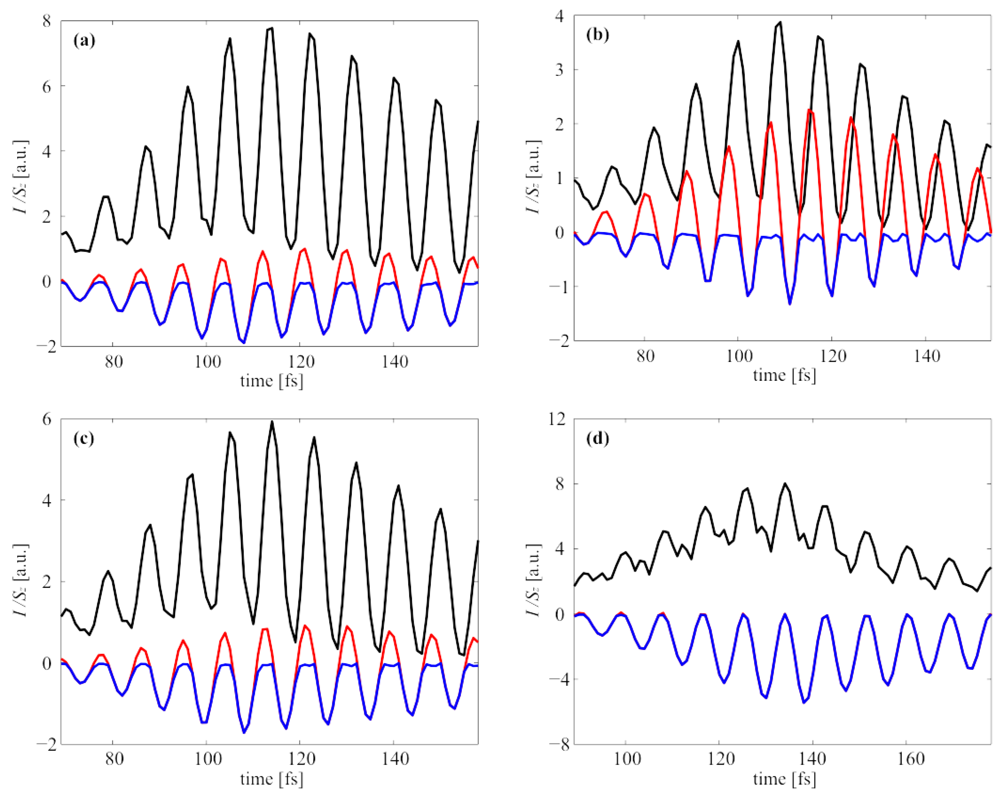
This section presents the results of studying the time dependences of the intensity and the longitudinal component of the pointing vector at the focus. Figure 14 depicts the dynamics of these values in the focal plane. In view of the fact that for different BZPs, the region of the minimum value of the Pointing vector longitudinal component is not formed on the axis, as in the case of continuous wave and phase BZP [7,10], we present two graphs for this characteristic of the electromagnetic field: on the axis and the minimum value in the focal plane.
It can be seen from Figure 14 that only for the phase BZP the minimum value of the Poynting vector longitudinal component is formed directly on the optical axis. However, if we look at the nature of the time dependence of the maximum intensity value and the minimum value of the Pointing vector, we can also notice that only for the phase BZP the oscillations of these values are in the same phase. For all other BZPs, the graphs of fluctuation are shifted.
4. Conclusions
In this research, the focusing of an ultrashort second-order CVB by BZPs from different materials (quartz, aluminum, gold, chromium) is considered by using the (FD)2TD method. It is shown that the relief material has a significant effect on the shape and maximum values of both the instantaneous and averaged intensity, as well as the maximum inverse energy flow. The formation of a reverse energy flow is possible only for the BZPs of quartz, aluminum and chromium. It is shown that the maximum intensity as the maximum energy backflow is given by the phase BZP. Field distributions close in all parameters to the field distributions formed in the focus area of phase BZP are obtained for aluminum BZP with a height of relief equal to 50 nm. The gold BZP with a height of relief equal to 140 nm seems unsuitable for focusing ultrashort second-order CVB. The carried out research will be useful in surface nanostructuring applications using tightly focused femtosecond pulses [36,37,45,46,47,48].
Author Contributions
Conceptualization E.K. and V.K.; methodology, E.K.; software, E.K.; validation, E.K. and V.K.; formal analysis, E.K.; investigation, E.K.; resources, E.K.; data curation, E.K. and V.K.; writing—original draft preparation, E.K. and V.K.; writing—review and editing, E.K. and V.K.; visualization, E.K.; supervision, V.K.; project administration, E.K.; funding acquisition, E.K. All authors have read and agreed to the published version of the manuscript.
Funding
The work was funded by the Russian Science Foundation under grant #22-12-00137.
Institutional Review Board Statement
Not applicable.
Informed Consent Statement
Not applicable.
Data Availability Statement
Not applicable.
Acknowledgments
We acknowledge support of RF Ministry of Science and Higher Education within a government project of the FSRC “Crystallography and Photonics” RAS.
Conflicts of Interest
The authors declare no conflict of interest. The funders had no role in the design of the study, in the collection, analyses, or interpretation of data, in the writing of the manuscript, or in the decision to publish the results.
References
- Zuo, R.; Liu, W.; Cheng, H.; Chen, S.; Tian, J. Breaking the Diffraction Limit with Radially Polarized Light Based on Dielectric Metalenses. Adv. Opt. Mat. 2018, 6, 1800795. [Google Scholar] [CrossRef]
- Chang, K.-H.; Chen, Y.-C.; Chang, W.-H.; Lee, P.-T. Efficient modulation of subwavelength focusing via metaaperture-based plasmonic lens for multifunction applications. Sci. Rep. 2018, 8, 13648. [Google Scholar] [CrossRef]
- Kotlyar, V.V.; Stafeev, S.S.; Nalimov, A.G. Vortex energy flow in the tight focus of a non-vortex field with circular polarization. Comput. Opt. 2020, 44, 5–11. [Google Scholar] [CrossRef]
- Wang, S.; Wu, P.C.; Su, V.-C.; Lai, Y.-C.; Chen, M.-K.; Kuo, H.Y.; Chen, B.H.; Han Chen, Y.; Huang, T.-T.; Wang, J.-H.; et al. A broadband achromatic metalens in the visible. Nat. Nanotechnol. 2018, 13, 227–232. [Google Scholar] [CrossRef]
- Kotlyar, V.V.; Stafeev, S.S.; Nalimov, A.G.; Kotlyar, M.V.; O’Faolain, L.; Kozlova, E.S. Tight focusing of laser light using a chromium Fresnel zone plate. Opt. Express 2017, 25, 19662–19671. [Google Scholar] [CrossRef]
- Zhuang, J.; Zhang, L.; Deng, D. Tight-focusing properties of linearly polarized circular Airy Gaussian vortex beam. Opt. Lett. 2020, 45, 296–299. [Google Scholar] [CrossRef]
- Kotlyar, V.V.; Stafeev, S.S.; Kovalev, A.A. Sharp focusing of a light field with polarization and phase singularities of an arbitrary order. Comput. Opt. 2019, 43, 337–346. [Google Scholar] [CrossRef]
- Li, M.; Cai, Y.; Yan, S.; Liang, Y.; Zhang, P.; Yao, B. Orbit-induced localized spin angular momentum in strong focusing of optical vectorial vortex beams. Phys. Rev. A 2018, 97, 053842. [Google Scholar] [CrossRef]
- Volpe, A.; Gaudiuso, C.; Ancona, A. Sorting of Particles Using Inertial Focusing and Laminar Vortex Technology: A Review. Micromachines 2019, 10, 594. [Google Scholar] [CrossRef]
- Stafeev, S.S.; Kozlova, E.S.; Nalimov, A.G. Focusing a second-order cylindrical vector beam with a gradient index Mikaelian lens. Comput. Opt. 2020, 44, 29–33. [Google Scholar] [CrossRef]
- Lavanya, M.; Thiruarul, D.; Rajesh, K.B.; Mahadevan, G.; Velauthapillai, D.; Jaroszewicz, Z. Energy flux density for higher-order cylindrical vector vortex beam tightly focused through a dielectric interface. J. Opt. 2021, 50, 548–558. [Google Scholar] [CrossRef]
- Rahimian, M.G.; Jain, A.; Larocque, H.; Corkum, P.B.; Karimi, E.; Bhardwaj, V.R. Spatially controlled nano-structuring of silicon with femtosecond vortex pulses. Sci. Rep. 2020, 10, 12643. [Google Scholar] [CrossRef] [PubMed]
- Kohmura, Y.; Zhakhovsky, V.; Takei, D.; Suzuki, Y.; Takeuchi, A.; Inoue, I.; Inubushi, Y.; Inogamov, N.; Ishikawa, T.; Yabashi, M. Nano-structuring of multi-layer material by single x-ray vortex pulse with femtosecond duration. Appl. Phys. Lett. 2018, 112, 123103. [Google Scholar] [CrossRef]
- Bhuyan, M.K.; Velpula, P.K.; Colombier, J.P.; Olivier, T.; Faure, N.; Stoian, R. Single-shot high aspect ratio bulk nanostructuring of fused silica using chirp-controlled ultrafast laser Bessel beams. Appl. Phys. Lett. 2014, 104, 021107. [Google Scholar] [CrossRef]
- Podlipnov, V.V.; Ivliev, N.A.; Khonina, S.N.; Nesterenko, D.V.; Vasilev, V.S.; Achimova, E.A. Investigation of photoinduced formation of microstructures on the surface of carbaseole-containing azopolymer depending on the power density of incident beams. Comput. Opt. 2018, 42, 779–785. [Google Scholar] [CrossRef]
- Chattaraj, S.; Madhukar, A. Multifunctional all-dielectric nano-optical systems using collective multipole Mie resonances: Toward on-chip integrated nanophotonics. J. Opt. Soc. Am. B 2016, 33, 2414–2423. [Google Scholar] [CrossRef]
- Bunandar, D.; Lazovich, T.; Gould, M.; Braid, R.; Ramey, C.; Harris, N.C. Programmable Nanophotonics for Computation. In Proceedings of the 2018 IEEE 15th International Conference on Group IV Photonics (GFP), Cancun, Mexico, 29–31 August 2018. [Google Scholar] [CrossRef]
- Xian, M.; Xu, Y.; Ouyang, X.; Cao, Y.; Lan, S.; Li, X. Segmented cylindrical vector beams for massively-encoded optical data storage. Sci. Bull. 2020, 65, 2072–2079. [Google Scholar] [CrossRef]
- Singh, B.K.; Nagar, H.; Roichman, Y.; Arie, A. Particle manipulation beyond the diffraction limit using structured super-oscillating light beams. Light Sci. Appl. 2017, 6, 17050. [Google Scholar] [CrossRef]
- Rodrigues Ribeiro, R.S.; Dahal, P.; Guerreiro, A.; Jorge, P.A.S.; Viegas, J. Fabrication of Fresnel plates on optical fibres by FIB milling for optical trapping, manipulation and detection of single cells. Sci. Rep. 2017, 7, 4485. [Google Scholar] [CrossRef]
- Kotlyar, V.V.; Nalimov, A.G.; Kovalev, A.A.; Porfirev, A.P.; Stafeev, S.S. Transfer of spin angular momentum to a dielectric particle. Comput. Opt. 2020, 44, 333–342. [Google Scholar] [CrossRef]
- Mendis, B.G. A semi-classical theory of magnetic inelastic scattering in transmission electron energy loss spectroscopy. Ultramicroscopy 2021, 230, 113390. [Google Scholar] [CrossRef] [PubMed]
- Meng, Z.; Traverso, A.J.; Ballmann, C.W.; Troyanova-Wood, M.A.; Yakovlev, V.V. Seeing cells in a new light: A renaissance of Brillouin spectroscopy. Adv. Opt. Photon. 2016, 8, 300–327. [Google Scholar] [CrossRef]
- Liu, Q.; Liu, T.; Yang, S.; Wang, T.; Wang, Y. Validation of vectorial theories for the focusing of high numerical aperture Fresnel zone plates. Opt. Commun. 2018, 429, 119–126. [Google Scholar] [CrossRef]
- Geints, Y.E.; Minin, O.V.; Panina, E.K.; Minin, I.V. Controlling near-field focusing of a mesoscale binary phase plate in an optical radiation field with circular polarization. Comput. Opt. 2021, 45, 512–519. [Google Scholar] [CrossRef]
- Huang, P.; Zhou, Z.; Ren, H. Fresnel zone plate fabricated using a polyvinyl chloride gel. Opt. Eng. 2018, 57, 117101. [Google Scholar] [CrossRef]
- Kim, J.; Kim, H.; Lee, G.-Y.; Kim, J.; Lee, B.; Jeong, Y. Numerical and Experimental Study on Multi-Focal Metallic Fresnel Zone Plates Designed by the Phase Selection Rule via Virtual Point Sources. Appl. Sci. 2018, 8, 449. [Google Scholar] [CrossRef]
- Kozlova, E.S.; Kotlyar, V.V. Simulation of tight focusing of laser light by gold zone plate. In Proceedings of the 20th International Conference on Transparent Optical Networks (ICTON), Bucharest, Romania, 1–5 July 2018. [Google Scholar] [CrossRef]
- Wang, H.; Deng, Y.; He, J.; Gao, P.; Yao, N.; Wang, C.; Luo, X. Subwavelength light focusing of plasmonic lens with dielectric filled nanoslits structures. J. Nanophotonics 2014, 8, 083079. [Google Scholar] [CrossRef]
- Zaitcev, V.D.; Stafeev, S.S.; Kotlyar, V.V. Diffraction of laser radiation by a binary zone plate with fractional order. Proc. SPIE 2021, 12295, 1229517. [Google Scholar] [CrossRef]
- Peng, R.; Li, X.; Zhao, Z.; Wang, C.; Hong, M.; Luo, X. Super-Resolution Long-Depth Focusing by Radially Polarized Light Irradiation Through Plasmonic Lens in Optical Meso-field. Plasmonics 2014, 9, 55–60. [Google Scholar] [CrossRef]
- Kozlova, E.S.; Kotlyar, V.V.; Stafeev, S.S.; Fomchenkov, S.A. Fresnel Zone Plate in Thin Aluminum Film. In Proceedings of the Photonics & Electromagnetics Research Symposium-Spring (PIERS-Spring), Rome, Italy, 17–20 June 2019; pp. 4333–4338. [Google Scholar] [CrossRef]
- Kozlova, E.; Stafeev, S.; Fomchenkov, S.; Podlipnov, V.; Savelyeva, A.; Kotlyar, V. Measuring of Transverse Energy Flows in a Focus of an Aluminum Lens. Photonics 2022, 9, 592. [Google Scholar] [CrossRef]
- Kozlov, S.A.; Samartsev, V.V. Fundamentals of Femtosecond Optics, 1st ed.; Woodhead Publishing: Sawston, UK, 2013. [Google Scholar]
- Kozlova, E.S.; Kotlyar, V.V. Temporary compression of femtosecond pulses in the focusof truncated microellipsoid. Comput. Opt. 2014, 38, 380–385. [Google Scholar] [CrossRef]
- Bruening, S.; Gillner, A.; Du, K. Multi beam microprocessing for printing and embossing applications with high power ultrashort pulsed lasers. Adv. Opt. Technol. 2021, 10, 25. [Google Scholar] [CrossRef]
- Yu, Y.; Bai, S.; Wang, S.; Hu, A. Ultrashort Pulsed Laser Manufacturing and Surface Processing of Microdevices. Engineering 2018, 4, 779–786. [Google Scholar] [CrossRef]
- Wang, X.; Yu, H.; Lia, P.; Zhang, Y.; Wen, Y.; Qiu, Y.; Liu, Z.; Li, Y.; Liu, L. Femtosecond laser-based processing methods and their applications in optical device manufacturing: A review. Opt. Laser Technol. 2021, 135, 106687. [Google Scholar] [CrossRef]
- Yulianto, N.; Kadja, G.T.M.; Bornemann, S.; Gahlawat, S.; Majid, N.; Triyana, K.; Abdi, F.F.; Wasisto, H.S.; Waag, A. Ultrashort Pulse Laser Lift-Off Processing of InGaN/GaN Light-Emitting Diode Chips. ACS Appl. Electron. Mater. 2021, 3, 778–788. [Google Scholar] [CrossRef]
- Latz, C.; Asshauer, T.; Rathjen, C.; Mirshahi, A. Femtosecond-Laser Assisted Surgery of the Eye: Overview and Impact of the Low-Energy Concept. Micromachines 2021, 12, 122. [Google Scholar] [CrossRef]
- Liebmann, M.; Treffer, A.; Bock, M.; Wallrabe, U.; Grunwald, R. Ultrashort Vortex Pulses with Controlled Spectral Gouy Rotation. Appl. Sci. 2020, 10, 4288. [Google Scholar] [CrossRef]
- Nie, J.; Liu, G.; Zhang, R. Propagation and spatiotemporal coupling characteristics of ultrashort Gaussian vortex pulse. Opt. Laser Technol. 2018, 101, 446–450. [Google Scholar] [CrossRef]
- Zhang, T.; Hu, H.; Chen, J.; Zhan, Q. Tunable mode-locked fiber laser to generate ultrashort cylindrical vector beams. Laser Phys. Lett. 2018, 18, 035102. [Google Scholar] [CrossRef]
- Chen, J.; Wan, C.; Chong, A.; Zhan, Q. Experimental demonstration of cylindrical vector spatiotemporal optical vortex. Nanophotonics 2021, 10, 427. [Google Scholar] [CrossRef]
- Li, Y.; Zhang, Y.; Zhu, Y. Probability distribution of the orbital angular momentum mode of the ultrashort Laguerre-Gaussian pulsed beam propagation in oceanic turbulence. Results Phys. 2018, 11, 698–705. [Google Scholar] [CrossRef]
- Zukersteina, M.; Hrabovsky, J.; Sladek, J.; Mirza, I.; Levy, Y.; Bulgakova, N.M. Formation of tubular structures and microneedles on silicon surface by doughnut-shaped ultrashort laser pulses. Appl. Surf. Sci. 2022, 592, 153228. [Google Scholar] [CrossRef]
- Syubaev, S.A.; Zhizhchenko, A.Y.; Pavlov, D.V.; Gurbatov, S.O.; Pustovalov, E.V.; Porfirev, A.P.; Khonina, S.N.; Kulinich, S.A.; Rayappan, J.B.B.; Kudryashov, S.I.; et al. Plasmonic Nanolenses Produced by Cylindrical Vector Beam Printing for Sensing Applications. Sci. Rep. 2019, 9, 19750. [Google Scholar] [CrossRef]
- Tsibidis, G.D.; Stratakis, E. Ripple formation on silver after irradiation with radially polarised ultrashort-pulsed lasers. J. Appl. Phys. 2017, 121, 163106. [Google Scholar] [CrossRef]
- Zhu, G.; Howe, J.; Durst, M.; Zipfel, W.; Xu, C. Simultaneous spatial and temporal focusing of femtosecond pulses. Opt. Express 2005, 13, 2153–2159. [Google Scholar] [CrossRef] [PubMed]
- Sergynin, S.K.; Khorin, P.A. Diffraction of pulsed linearly polarized Gaussian laser beams on a spiral phase plate. In Proceedings of the 2022 VIII International Conference on Information Technology and Nanotechnology (ITNT), Samara, Russia, 23–27 May 2022; pp. 1–6. [Google Scholar] [CrossRef]
- Khonina, S.N.; Golub, I. Tighter focus for ultrashort pulse vector light beams: Change of the relative contribution of different field components to the focal spot upon pulse shortening. J. Opt. Soc. Am. A 2018, 35, 985–991. [Google Scholar] [CrossRef]
- Chen, J.; Yu, L.; Wan, C.; Zhan, Q. Spin–Orbit Coupling within Tightly Focused Circularly Polarized Spatiotemporal Vortex Wavepacket. ACS Photonics 2022, 9, 793–799. [Google Scholar] [CrossRef]
- Tang, Y.; Perrie, W.; Rico Sierra, D.; Li, Q.; Liu, D.; Edwardson, S.P.; Dearden, G. Laser–Material Interactions of High-Quality Ultrashort Pulsed Vector Vortex Beams. Micromachines 2021, 12, 376. [Google Scholar] [CrossRef]
- Couairon, A.; Sudrie, L.; Franco, M.; Prade, B.; Mysyrowicz, A. Surface physics, nanoscale physics, low-dimensional systems-Filamentation and damage in fused silica induced by tightly focused femtosecond laser pulses. Phys. Rev. B 2005, 71, 125435. [Google Scholar] [CrossRef]
- Vial, A.; Laroche, T.; Dridi, M.; Le Cunff, L. A new model of dispersion for metals leading to a more accurate modeling of plasmonic structures using the FDTD method. Appl. Phys. A 2011, 103, 849–853. [Google Scholar] [CrossRef]
- Rakic, A.D.; Djurisic, A.B.; Elazar, J.M.; Majewski, M.L. Optical properties of metallic films for vertical-cavity optoelectronic devices. Appl. Opt. 1998, 37, 5271–5283. [Google Scholar] [CrossRef] [PubMed]
- Kotlyar, V.V.; Nalimov, A.G.; Stafeev, S.S.; O’Faolain, L. Single metalens for generating polarization and phase singularities leading to a reverse flow of energy. J. Opt. 2019, 21, 055004. [Google Scholar] [CrossRef]
- Kozlova, E.S.; Stafeev, S.S.; Fomchenkov, S.A.; Podlipnov, V.V.; Kotlyar, V.V. Transverse intensity at the tight focus of a second-order cylindrical vector beam. Comput. Opt. 2021, 45, 165–171. [Google Scholar] [CrossRef]
- Golovashkin, D.L.; Kasanskiy, N.L. Solving diffractive optics problem using graphics processing units. Opt. Mem. Neural Netw. Inf. Opt. 2011, 20, 85–89. [Google Scholar] [CrossRef]
- Kazanskiy, N.L. Modeling diffractive optics elements and devices. Proc. SPIE 2018, 10774, 107740O. [Google Scholar] [CrossRef]
- Kazanskiy, N.L.; Skidanov, R.V. Technological line for creation and research of diffractive optical elements. Proc. SPIE 2019, 11146, 111460W. [Google Scholar] [CrossRef]
Figure 1.
The template of BZP in transverse (a), longitudinal (b) planes and in 3D projection (c) illuminated by incident light (schematic representation).
Figure 1.
The template of BZP in transverse (a), longitudinal (b) planes and in 3D projection (c) illuminated by incident light (schematic representation).

Figure 2.
The permittivities of proposed materials plotted by using models (2)–(3) and parameters from Table 2, Table 3, Table 4 and Table 5. Real part is presented by blue solid line, image part is presented by green dashed line.
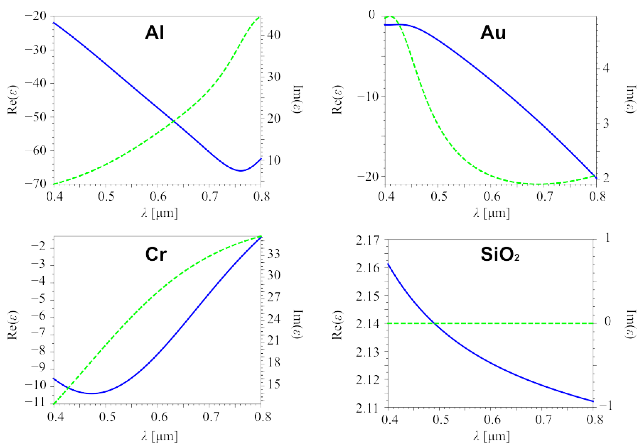
Figure 3.
The refractive indices of proposed materials plotted by using models (2)–(3) and parameters from Table 2, Table 3, Table 4 and Table 5. Real part is presented by blue solid line, image part is presented by green dashed line.

Figure 4.
The electric field components Ex (a) and Ey (b) of the incident CVB.

Figure 5.
The instantaneous longitudinal pattern of the intensity of the second-order CVB propagating in free space at time of 22.01 fs (a),65.05 fs (b), 97.06 fs (c), and 120.08 fs (d).
Figure 5.
The instantaneous longitudinal pattern of the intensity of the second-order CVB propagating in free space at time of 22.01 fs (a),65.05 fs (b), 97.06 fs (c), and 120.08 fs (d).

Figure 6.
The instantaneous pattern of the intensity of the second-order CVB in the focus of the BZP with relief from: aluminum with height of 50 nm (a), gold with height of 140 nm (b), chrome with height of 70 nm (c), and quartz with height of 532 nm (d).
Figure 6.
The instantaneous pattern of the intensity of the second-order CVB in the focus of the BZP with relief from: aluminum with height of 50 nm (a), gold with height of 140 nm (b), chrome with height of 70 nm (c), and quartz with height of 532 nm (d).
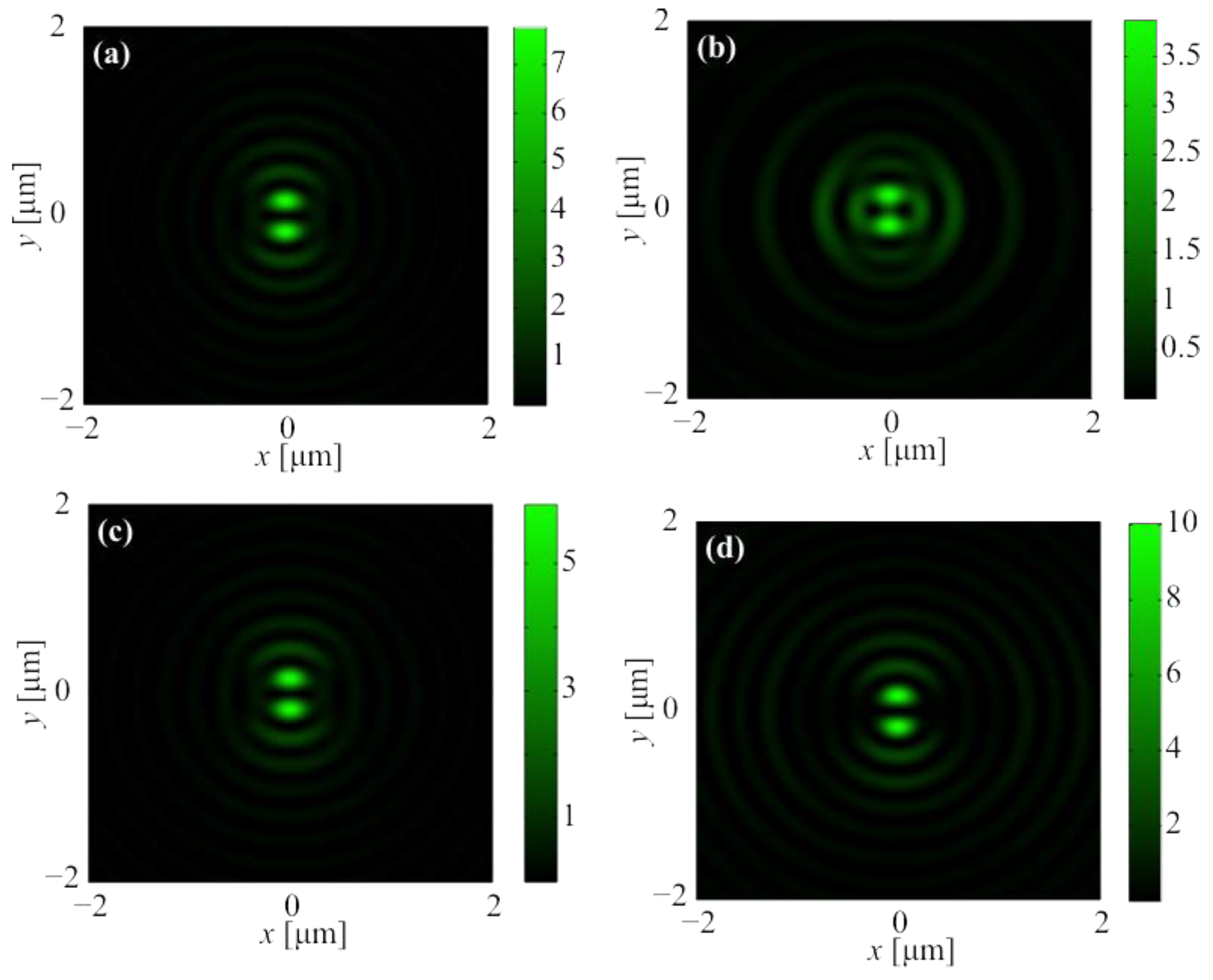
Figure 7.
The instantaneous pattern of the longitudinal component of the Poynting vector Sz of the second-order CVB in the focus of the BZP with relief from: aluminum with height of 50 nm (a), gold with height of 140 nm (b), chrome with height of 70 nm (c), and quartz with height of 532 nm (d).
Figure 7.
The instantaneous pattern of the longitudinal component of the Poynting vector Sz of the second-order CVB in the focus of the BZP with relief from: aluminum with height of 50 nm (a), gold with height of 140 nm (b), chrome with height of 70 nm (c), and quartz with height of 532 nm (d).
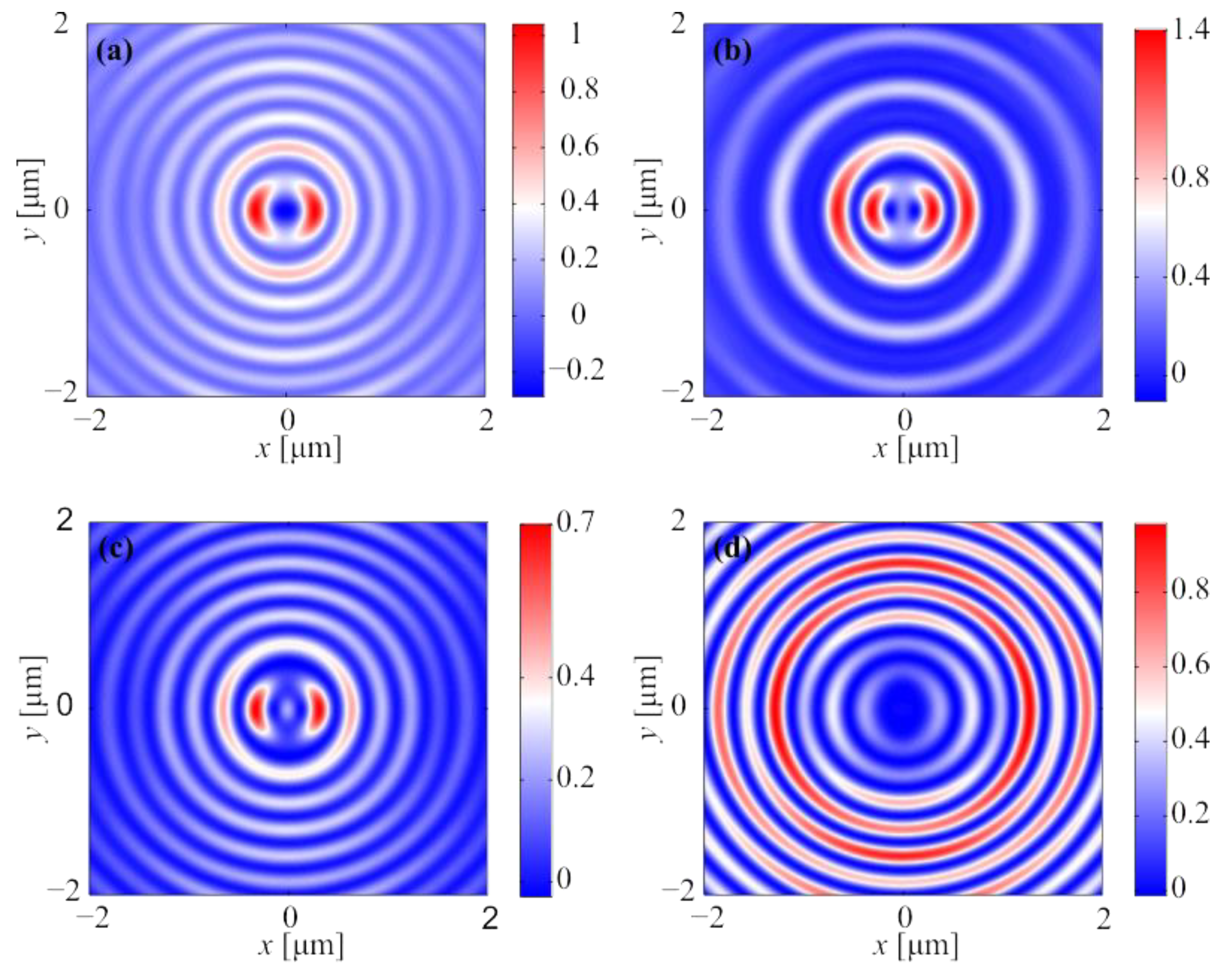
Figure 8.
The instantaneous longitudinal of the intensity of the second-order CVB focused by aluminum BZP pattern in XZ-plane (a–c) and YZ-plane (d–f) at the time moment of 100.07 fs (a,d), 114.08 fs (b,e), and 188.13 fs (c,f).
Figure 8.
The instantaneous longitudinal of the intensity of the second-order CVB focused by aluminum BZP pattern in XZ-plane (a–c) and YZ-plane (d–f) at the time moment of 100.07 fs (a,d), 114.08 fs (b,e), and 188.13 fs (c,f).
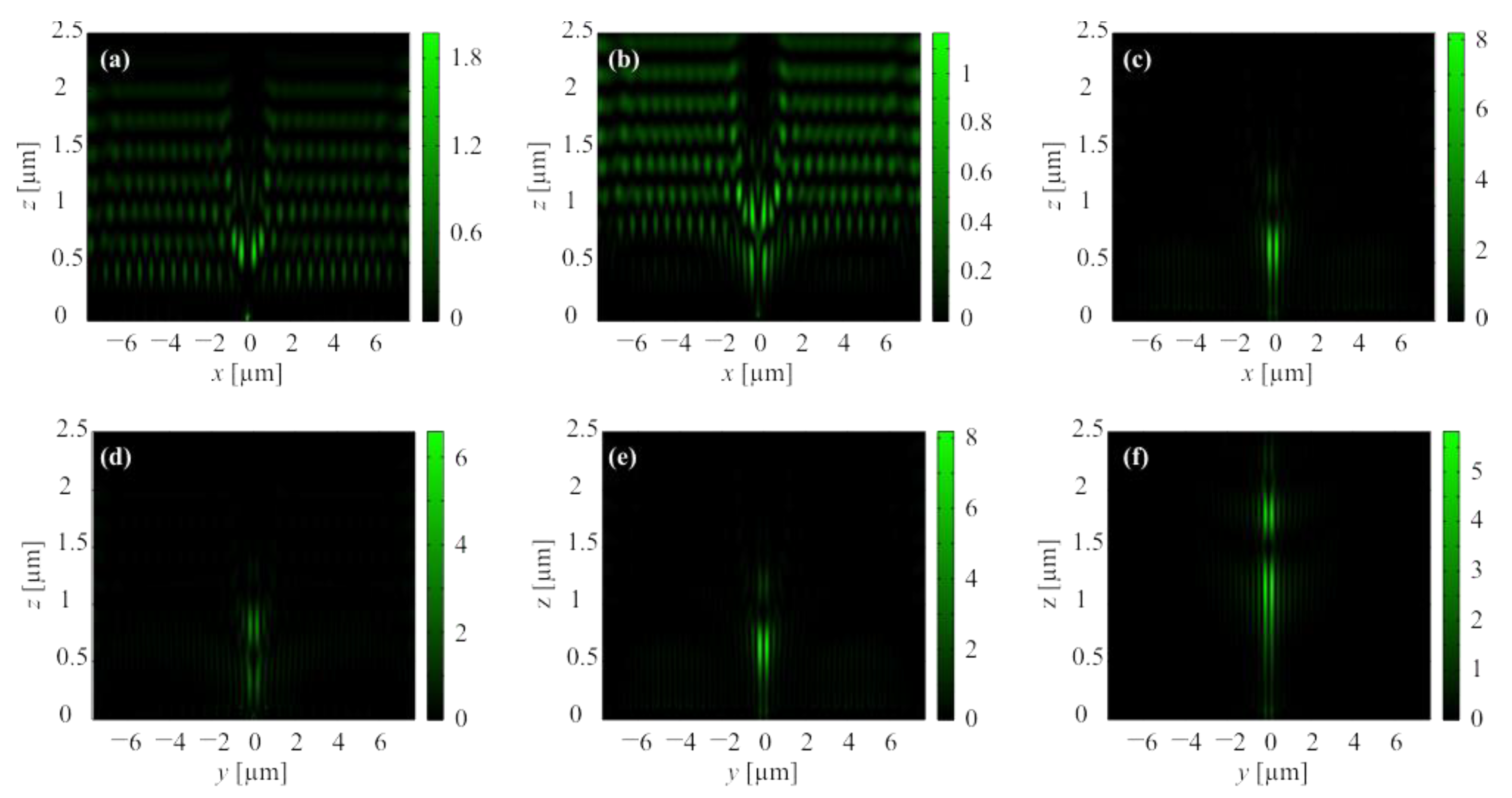
Figure 9.
The instantaneous longitudinal of the intensity of the second-order CVB focused by gold BZP pattern in XZ-plane (a–c) and YZ-plane (d–f) at the time moment of 95.06 fs (a,d), 109.08 fs (b,e), and 183.13 fs (c,f).
Figure 9.
The instantaneous longitudinal of the intensity of the second-order CVB focused by gold BZP pattern in XZ-plane (a–c) and YZ-plane (d–f) at the time moment of 95.06 fs (a,d), 109.08 fs (b,e), and 183.13 fs (c,f).

Figure 10.
The instantaneous longitudinal of the intensity of the second-order CVB focused by chromium BZP pattern in XZ-plane (a–c) and YZ-plane (d–f) at the time moment of 100.07 fs (a,d), 114.08 fs (b,e), and 188.13 fs (c,f).
Figure 10.
The instantaneous longitudinal of the intensity of the second-order CVB focused by chromium BZP pattern in XZ-plane (a–c) and YZ-plane (d–f) at the time moment of 100.07 fs (a,d), 114.08 fs (b,e), and 188.13 fs (c,f).
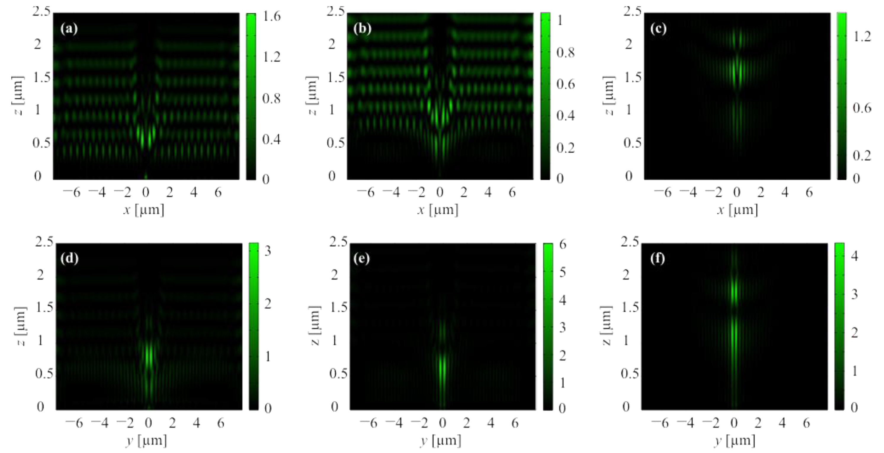
Figure 11.
The instantaneous longitudinal of the intensity of the second-order CVB focused by quartz BZP pattern in XZ-plane (a–c) and YZ-plane (d–f) at the time moment of 120.08 fs (a,d), 134.09 fs (b,e), and 208.14 fs (c,f).
Figure 11.
The instantaneous longitudinal of the intensity of the second-order CVB focused by quartz BZP pattern in XZ-plane (a–c) and YZ-plane (d–f) at the time moment of 120.08 fs (a,d), 134.09 fs (b,e), and 208.14 fs (c,f).
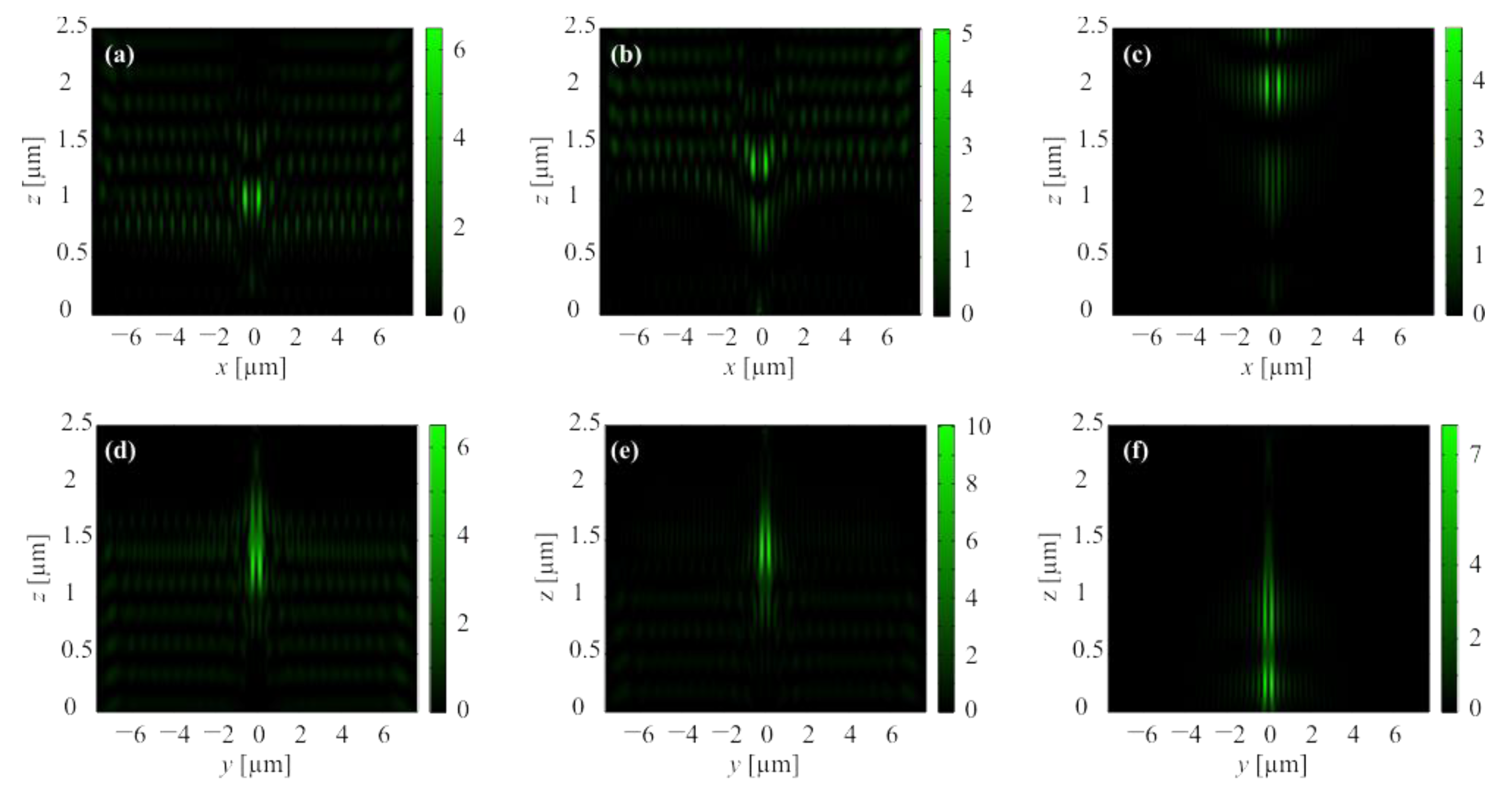
Figure 12.
The averaged pattern of the intensity of the second-order CVB in the focus of the BZP with relief from: aluminum with height of 50 nm (a), gold with height of 140 nm (b), chrome with height of 70 nm (c), and quartz with height of 532 nm (d).
Figure 12.
The averaged pattern of the intensity of the second-order CVB in the focus of the BZP with relief from: aluminum with height of 50 nm (a), gold with height of 140 nm (b), chrome with height of 70 nm (c), and quartz with height of 532 nm (d).
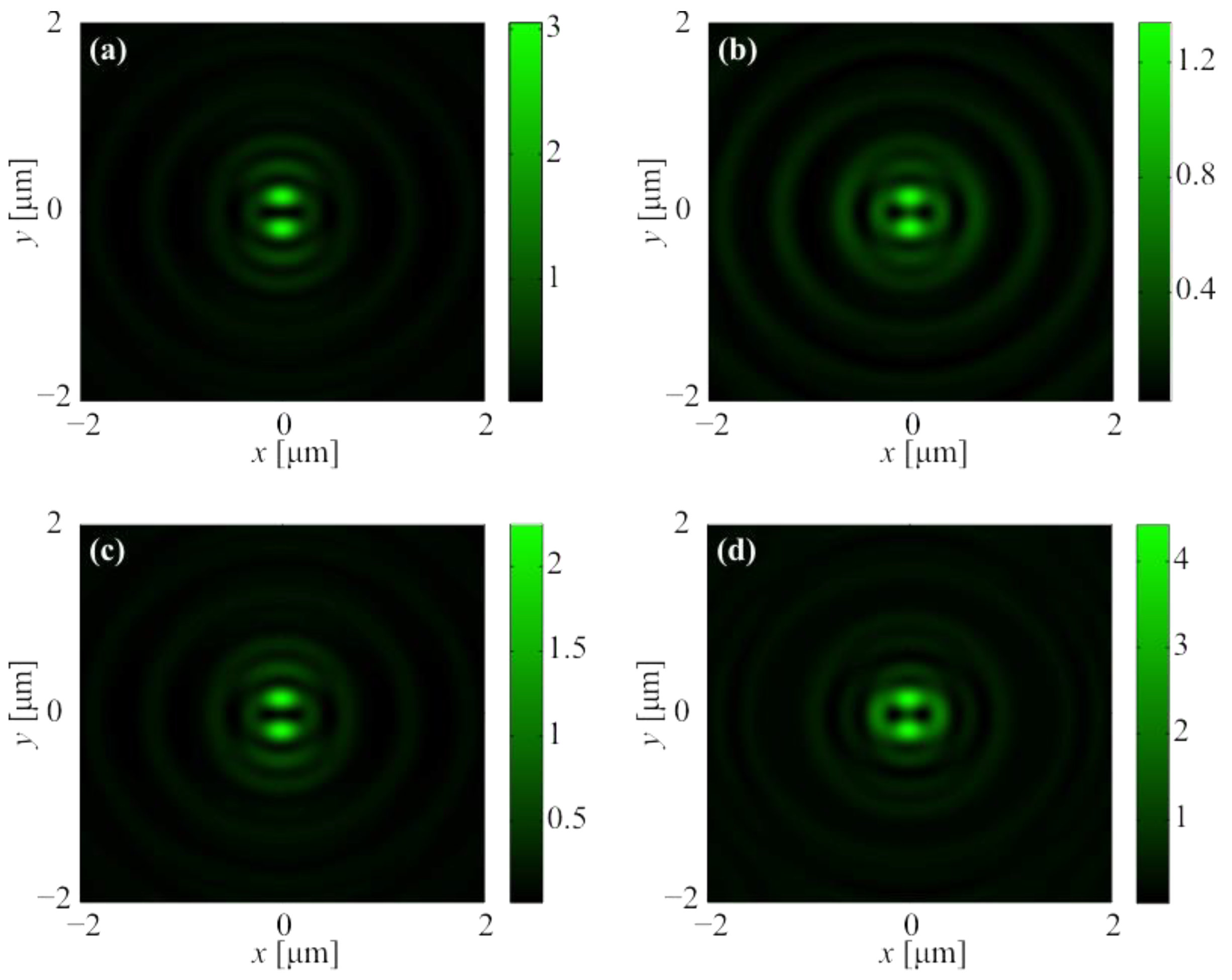
Figure 13.
The averaged pattern of the longitudinal component of the Poynting vector Sz of the second-order CVB in the focus of the BZP with relief from: aluminum with height of 50 nm (a), gold with height of 140 nm (b), chrome with height of 70 nm (c), and quartz with height of 532 nm (d).
Figure 13.
The averaged pattern of the longitudinal component of the Poynting vector Sz of the second-order CVB in the focus of the BZP with relief from: aluminum with height of 50 nm (a), gold with height of 140 nm (b), chrome with height of 70 nm (c), and quartz with height of 532 nm (d).
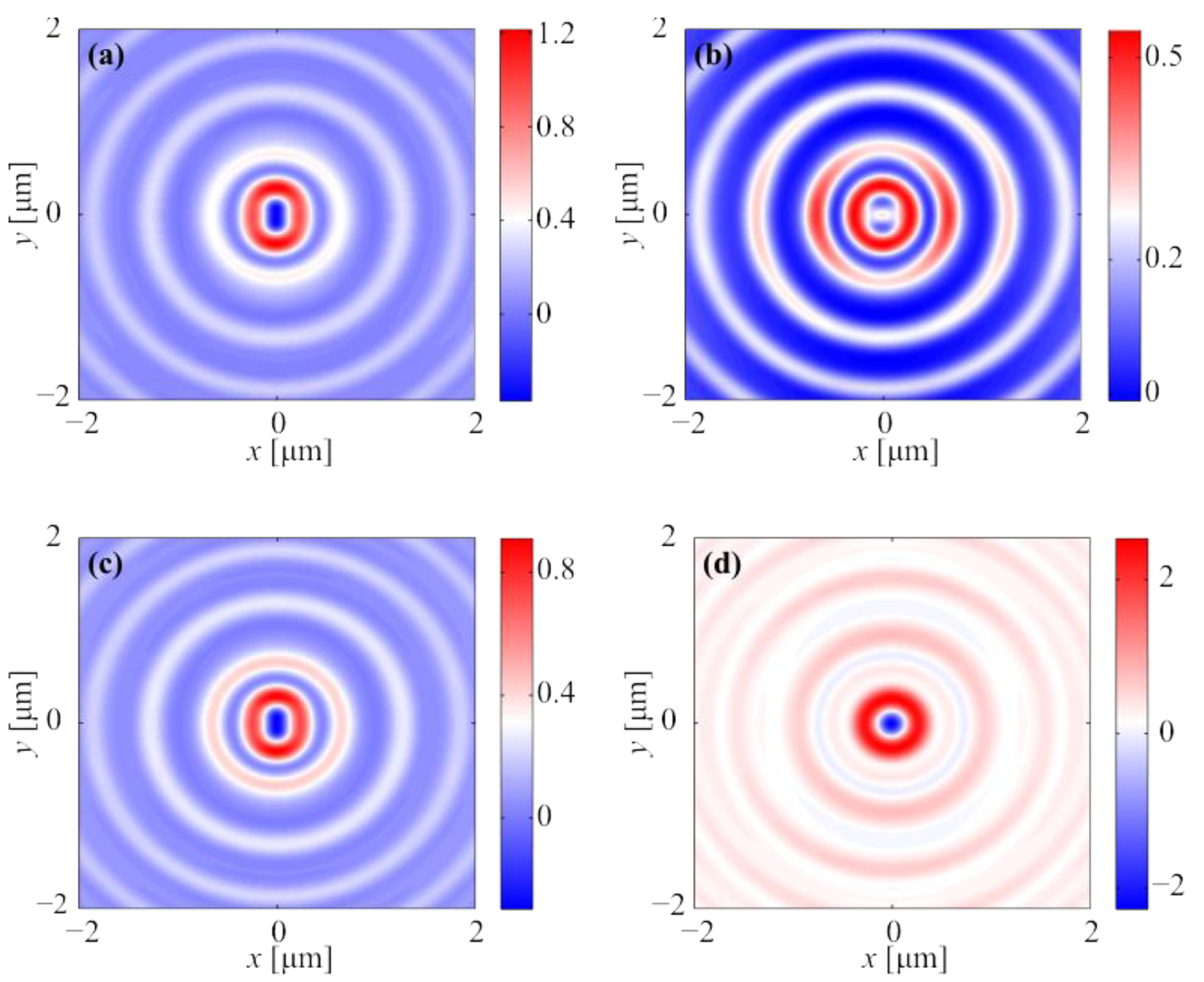
Figure 14.
The time dynamics of the intensity I (black line), the longitudinal component of the Poynting on the optical axis Sz (red line), and minimum of the longitudinal component of the Poynting vector Sz (blue line) of the second-order CVB in the focus of the BZP with relief from: aluminum with height of 50 nm (a), gold with height of 140 nm (b), chrome with height of 70 nm (c), and silica glass with height of 532 nm (d).

Table 1.
Radii of BZP’s zones.
| m | 1 | 2 | 3 | 4 | 5 | 6 | 7 | 8 | 9 |
| rm, μm | 0.595 | 0.921 | 1.219 | 1.505 | 1.784 | 2.060 | 2.334 | 2.606 | 2.877 |
| m | 10 | 11 | 12 | 13 | 14 | 15 | 16 | 17 | 18 |
| rm, μm | 3.147 | 3.417 | 3.686 | 3.954 | 4.223 | 4.491 | 4.758 | 5.026 | 5.293 |
| m | 19 | 20 | 21 | 22 | 23 | 24 | 25 | 26 | 27 |
| rm, μm | 5.561 | 5.828 | 6.095 | 6.362 | 6.629 | 6.896 | 7.162 | 7.429 | 7.696 |
Table 2.
Parameters for the Sellmeier ‘s permittivity model of quartz calculated using experimental results in [54].
Table 2.
Parameters for the Sellmeier ‘s permittivity model of quartz calculated using experimental results in [54].
| j | Δεj | λj | ηj |
|---|---|---|---|
| 1 | 0.69616630 | 0.06840430 | 0 |
| 2 | 0.40794260 | 0.11624140 | 0 |
| 3 | 0.89747928 | 9.88961612 | 0 |
| ε∞ = 1 | |||
Table 3.
Parameters for the Drude–Lorentz’s permittivity model of aluminum calculated using experimental results in [55,56].
| j | Aj | ωj | δj |
|---|---|---|---|
| 1 | 1940.97224801 | 0.82045170 | 0.84324200 |
| 2 | 4.70650987 | 7.81961316 | 0.79006450 |
| 3 | 11.39553922 | 9.15664513 | 3.42108050 |
| 4 | 0.55813006 | 17.58906478 | 8.56409500 |
| ε∞ = 1 | |||
| ωp = 54.86566321 | |||
| νc = 0.11901600 | |||
Table 4.
Parameters for the Drude–Lorentz’s permittivity model of gold calculated using experimental results in [55,56].
| j | Aj | ωj | δj |
|---|---|---|---|
| 1 | 11.36293409 | 2.10177425 | 0.61027400 |
| 2 | 1.18363911 | 4.20354850 | 0.87362900 |
| 3 | 0.65677021 | 15.03654881 | 2.20306450 |
| 4 | 2.64548647 | 21.79767648 | 6.31500000 |
| 5 | 2.01482608 | 67.45935814 | 5.60642000 |
| ε∞ = 1 | |||
| ωp = 39.86873462 | |||
| νc = 0.13420950 | |||
Publisher’s Note: MDPI stays neutral with regard to jurisdictional claims in published maps and institutional affiliations. |
© 2022 by the authors. Licensee MDPI, Basel, Switzerland. This article is an open access article distributed under the terms and conditions of the Creative Commons Attribution (CC BY) license (https://creativecommons.org/licenses/by/4.0/).
Share and Cite
MDPI and ACS Style
Kozlova, E.; Kotlyar, V. Ultrashort Laser Pulse Focusing by Amplitude and Phase Zone Plates. Photonics 2022, 9, 662. https://doi.org/10.3390/photonics9090662
AMA Style
Kozlova E, Kotlyar V. Ultrashort Laser Pulse Focusing by Amplitude and Phase Zone Plates. Photonics. 2022; 9(9):662. https://doi.org/10.3390/photonics9090662
Chicago/Turabian StyleKozlova, Elena, and Victor Kotlyar. 2022. "Ultrashort Laser Pulse Focusing by Amplitude and Phase Zone Plates" Photonics 9, no. 9: 662. https://doi.org/10.3390/photonics9090662
Note that from the first issue of 2016, this journal uses article numbers instead of page numbers. See further details here.