Review

Application of Adaptive Optics in Ophthalmology

1
School of Physics and Optoelectronic Engineering, Xidian University, Xi’an 710071, China
2
CAS Key Laboratory of Spectral Imaging Technology, Xi’an Institute of Optics and Precision Mechanics, Chinese Academy of Sciences, Xi’an 710119, China
3
Department of Ophthalmology, Peking University Shenzhen Hospital, Shenzhen 518035, China
*
Author to whom correspondence should be addressed.
Photonics 2022, 9(5), 288; https://doi.org/10.3390/photonics9050288
Submission received: 30 November 2021 / Revised: 28 March 2022 / Accepted: 19 April 2022 / Published: 23 April 2022
(This article belongs to the Special Issue Adaptive Optics for Biological Imaging)

Abstract

:
The eye, the photoreceptive organ used to perceive the external environment, is of great importance to humans. It has been proven that some diseases in humans are accompanied by fundus changes; therefore, the health status of people may be interpreted from retinal images. However, the human eye is not a perfect refractive system for the existence of ocular aberrations. These aberrations not only affect the ability of human visual discrimination and recognition, but restrict the observation of the fine structures of human eye and reduce the possibility of exploring the mechanisms of eye disease. Adaptive optics (AO) is a technique that corrects optical wavefront aberrations. Once integrated into ophthalmoscopes, AO enables retinal imaging at the cellular level. This paper illustrates the principle of AO in correcting wavefront aberrations in human eyes, and then reviews the applications and advances of AO in ophthalmology, including the adaptive optics fundus camera (AO-FC), the adaptive optics scanning laser ophthalmoscope (AO-SLO), the adaptive optics optical coherence tomography (AO-OCT), and their combined multimodal imaging technologies. The future development trend of AO in ophthalmology is also prospected.

1. Introduction

The eye is one of the most important organs for humans to understand their external environment. Most of the knowledge and memory stored in the brain is acquired through the eyes. Further, some diseases, such as diabetes, high blood pressure, atherosclerosis, etc., can be diagnosed by examination of the fundus, which provides a way to interpret the health status of the body. However, it is not easy to detect early retinopathy and fundus lesions, which may cause irreversible visual impairment and even blindness if not treated in time. Fundus imaging is generally used for detecting and diagnosing human diseases that influence the retina. Some kinds of retinal imaging technologies, such as optical coherence tomography (OCT) [1], flood-illumination fundus camera (FC) [2], and scanning laser ophthalmoscopy (SLO) [3], can obtain living human retinal images, but none of them can provide details at the cellular level due to the resolution limitations imposed by aberrations in the human eye. Adaptive optics (AO) provides a solution for ophthalmic imaging with high resolution, which is close to the diffraction limit, to accurately obtain the structural and functional information of retina.
The idea of AO comes from astronomical observations [4], where AO is used to compensate the dynamic wavefront distortion caused by atmospheric turbulence and allows a telescope to achieve diffraction-limited imaging from the ground. Subsequently, AO has been rapidly developed and applied in the military, astronomy, industrial, civil and medical fields. AO in ophthalmology started in the early 1990s [5], and was mainly employed in three imaging modalities, including FC, SLO and OCT. Since then, it has achieved huge progress in the last ~25 years. Like the atmosphere, the human eye is optically imperfect: it suffers from wavefront aberrations whose pattern and amount differ between individuals. In ophthalmic medicine, AO is used to measure and correct the wavefront aberrations in the human eyes and optical systems through a closed-loop control (detection–control–correction), improving the lateral optical resolution from 10–15 μm to ~2 μm, enabling retinal imaging with cellular-level resolution [6,7,8,9,10]. These improved images can help doctors to detect early retinopathy and fundus lesions, determine the cause and course of eye disease, and evaluate the subsequent treatment. The combination of AO and retinal imaging devices is of great significance and has the potential to become a general tool for the early and clinical detection and diagnosis of some retinal diseases.
In this paper, the principle of AO in correcting human eye aberrations is introduced. Several AO-based ophthalmic imaging technologies, including adaptive optics fundus camera (AO-FC), adaptive optics scanning laser ophthalmoscope (AO-SLO), adaptive optics optical coherence tomography (AO-OCT), and their combined multimodal AO imaging techniques are illustrated. The applications of the AO retinal imaging techniques in ophthalmic medicine are reviewed. Furthermore, the development trend of AO in ophthalmology is discussed.

2. Principles and Methods

2.1. Wavefront Aberration in Human Eyes

The human eye is mainly composed of the cornea, the anterior chamber, the lens, the vitreous body, the retina, etc. The retina is a light-sensitive layer with a sophisticated structure that lines the inner surface of the eye. This layer receives images coming through the eye’s lens and sends the processed signals along the optic nerve to the brain. Human eyes are not ideal refractive systems, and they are sensitive to the wavelength and intensity of light. When light enters the human eye, it produces chromatic and monochromatic aberrations. Chromatic aberrations can be overcome by using a single-wavelength light source. However, monochromatic aberrations are wavelength-independent and are affected by many complex factors, including variations in the shape of the tear film, cornea, and lens [11]. Monochromatic aberrations are commonly divided into low-order and high-order aberrations. Low-order aberrations can be corrected using spherical and cylindrical lenses; but higher-order aberrations can significantly reduce lateral resolution and degrade retinal image quality with increasing pupil size of the human eye [12,13]. In daily life, people can see objects clearly because the human eye can limit the effect of aberration on vision by adjusting the size of the pupils. These wavefront aberrations usually limit the resolution of human eyes to ~10–15 μm, far from the theoretical lateral resolution of ~2 μm according to the diffraction limit formula, r = 0.61λ/NA (r is the resolution, λ is the imaging wavelength, and NA is the numerical aperture).
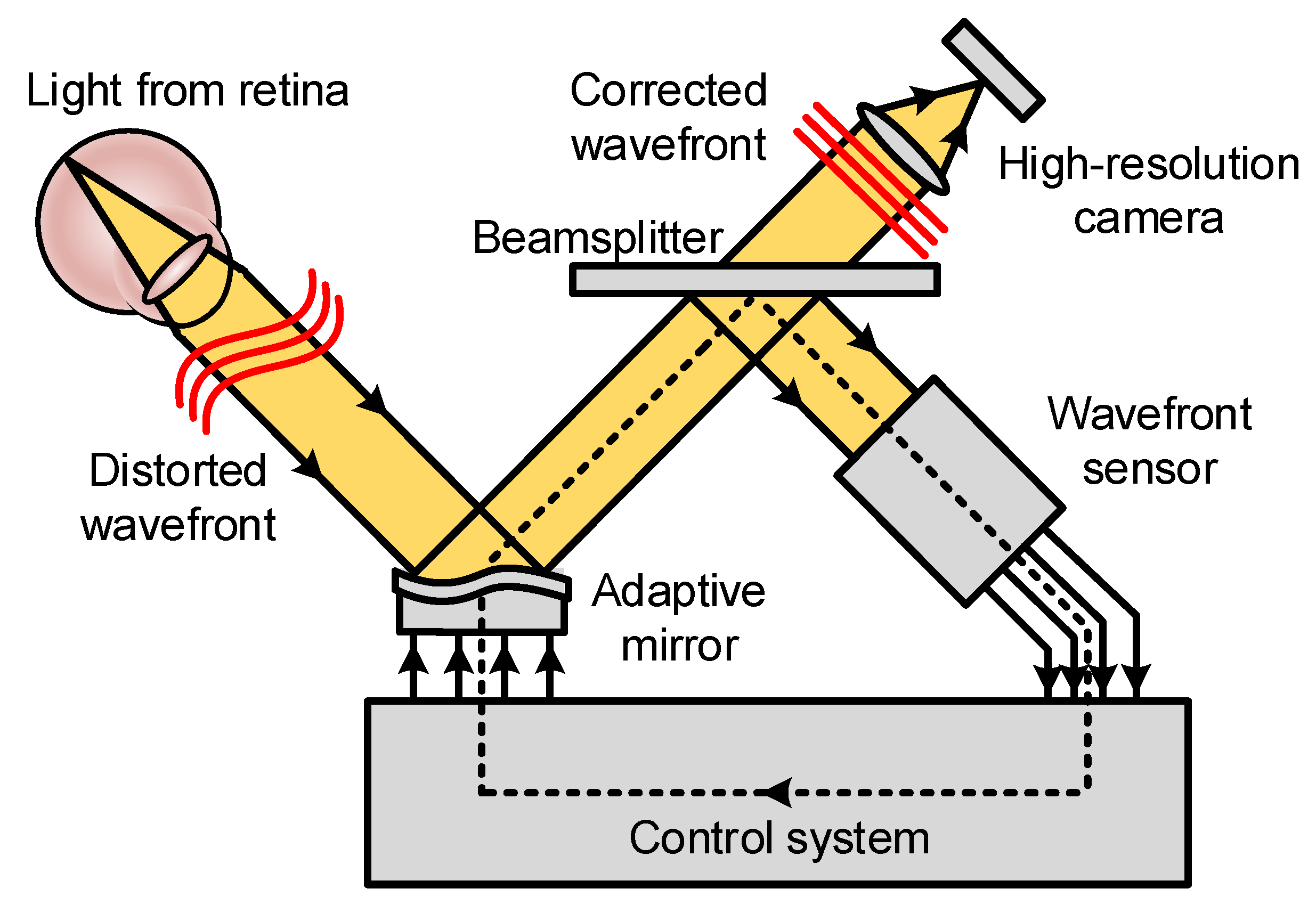
A comparison of wavefront shape between an ideal eye and a normal eye is shown in Figure 1. In the ideal eye, the light reflected from the fundus forms a flat wavefront after passing through the normal refractive medium. The aberration in the normal eye causes the reflected light from the fundus to form a distorted wavefront, which limits the resolution of the conventional fundus imaging techniques [6].

2.2. Basic Principles of Adaptive Optics

The AO system is an automatic control system that typically comprises a wavefront sensor, a wavefront controller, and a wavefront corrector. By detecting, controlling, and correcting the optical wavefront in real time, the AO system can actively adapt to the changes of external condition and maintain a good working state [14]. Modern AO retinal imaging systems can be divided into two types according to their different wavefront detection methods. One is based on geometric optics, wherein it uses wavefront sensors to directly measure the distorted wavefront, also known as the direct method. The corresponding AO system is referred to as hardware AO (HAO), which is usually composed of a wavefront sensor such as Shack-Hartmann wavefront sensor (SHWS), a compensator such as deformation mirror (DM) or liquid crystal spatial light modulator (LC-SLM), and the closed-loop control software between them. The direct method has the merits of high correction speed and detection accuracy, but it suffers from hardware complexity and high cost, relatively low spatial resolution, and limited dynamic range; moreover, a good “guide star” is necessary for the samples. The other is based on the iterative algorithm to indirectly deduce the wavefront through a series of images, also known as the indirect method, including sensorless AO (SAO) and computational AO (CAO) [8]. The indirect methods do not need an additional wavefront sensor, so the optical system is greatly simplified; their major disadvantage is their low speed (seconds to minutes) due to the collection of many images [15], leading to at least 10× slower speed compared to direct method (milliseconds).
Figure 2 shows the schematic diagram of a sensor-based AO system for retinal imaging [7,16]. Light focuses on the retina after passing through the cornea, lens, vitreous body, and other eyeball tissues. The reflected light from the retina passes through the cornea again and forms a distorted wavefront. A wavefront sensor is used to record the ocular wavefront aberrations and calculate the distortion degree. Then, the wavefront aberration is transmitted to the wavefront controller and converted to a control signal. This signal drives the adaptive mirror to produce the corresponding deformation for the correction of distorted wavefront. Finally, the corrected flat wavefront is acquired, and the high-resolution image is acquired by a CCD camera. Sensor-based AO is optimized for a single depth within the sample and is sensitive to system misalignment, irregularly shaped pupils, cloudy corneas, or other ocular opacities may obscure the detection of the ocular aberrations.

2.3. Sensorless AO and Computational AO

Compared with HAO, which uses a wavefront sensor and wavefront shaping device for wavefront aberrations correction, SAO eliminates a wavefront sensor and uses the properties of the image itself to estimate the wavefront quality [17,18,19,20,21]; CAO eliminates both the wavefront sensor and wavefront shaping, further omits the need to iterate a control algorithm while imaging, and modifies the phase of the data to correct optical aberrations [22,23,24,25]. Both SAO and CAO exploit optimization algorithms for aberration correction, which reduces the complexity and cost of the AO system and offers versatility at the expense of wavefront correction speed. Meanwhile, they require image stability or phase stability during the collection time.
Many SAO control algorithms and image quality metrics have been described and evaluated [18,26,27,28,29,30,31]. They can mainly be divided into two categories according to operating principle. One is to seek the optimum solution (control voltages or aberration modes) in line with desired system metrics from the numerous solutions (mostly random); the other is to seek the analytic relation between system metrics and the aberrations to attain the approximate solutions [18]. A stochastic parallel gradient descent (SPGD) algorithm was used in SAO-SLO for retinal imaging [17]. Moreover, a lot of retinal tracking and image registration algorithms were applied in the AO-SLO (see Section 3.2.5). SAO-OCT retinal imaging was demonstrated by the implementations of SPGD [20], coordinated search (CS) algorithm [19,32], hill climbing algorithm [33], and data-based online nonlinear extremum-seeker (DONE) algorithm [34], etc. Recently, some deep learning methods [35], such as deep reinforcement learning [36,37] and convolutional neural networks (CNNs) [38,39], have been applied in SAO systems in combination with SLO or OCT. Many of these features and aberration correction algorithms used in SAO could be implemented in CAO [40]. For example, an SPGD algorithm was introduced into CAO-OCT for automated fast computational aberration correction [40].

3. Application of Adaptive Optics in Ophthalmology

In 1994, Liang et al. measured wavefront aberrations of the human eye with SHWS, and reconstructed the actual wavefront via wavefront estimation with Zernike polynomials [5]. Then, they built an AO-FC for retinal imaging for the first time in 1997 [41]. However, the early AO retinal imaging system was only used for laboratory research, instead of clinical ophthalmology. With the development of laser, detector, corrector and other related techniques, AO has been applied to ophthalmology in combination with FC, SLO and OCT, endowing both structural and functional retinal imaging with greatly improved imaging performance metrics, such as resolution, imaging speed, aberration detection and correction ability. These AO-based techniques can be used to image retina with a resolution close to the diffraction limit, and are expected to become effective auxiliary tools for the examination and diagnosis of eye diseases in clinic [8,13].

3.1. Adaptive Optics Fundus Camera (AO-FC)

FC has been widely applied in the clinical diagnosis of ophthalmic diseases and is mainly used for large-scale retinal imaging and retinal fluorescein angiography by employing conventional flood-illumination and high-sensitivity CCD detection, with the advantages of simplicity of hardware, ease of use, and intuitive imaging. However, the CCD sensor detects light from everywhere, including scattered light from the anterior segment and other adjacent layers, which results in low image contrast of the retina. In addition, since traditional FCs cannot correct eye aberration according to individual differences and dynamic changes, their lateral resolution is limited to 10 μm or more.
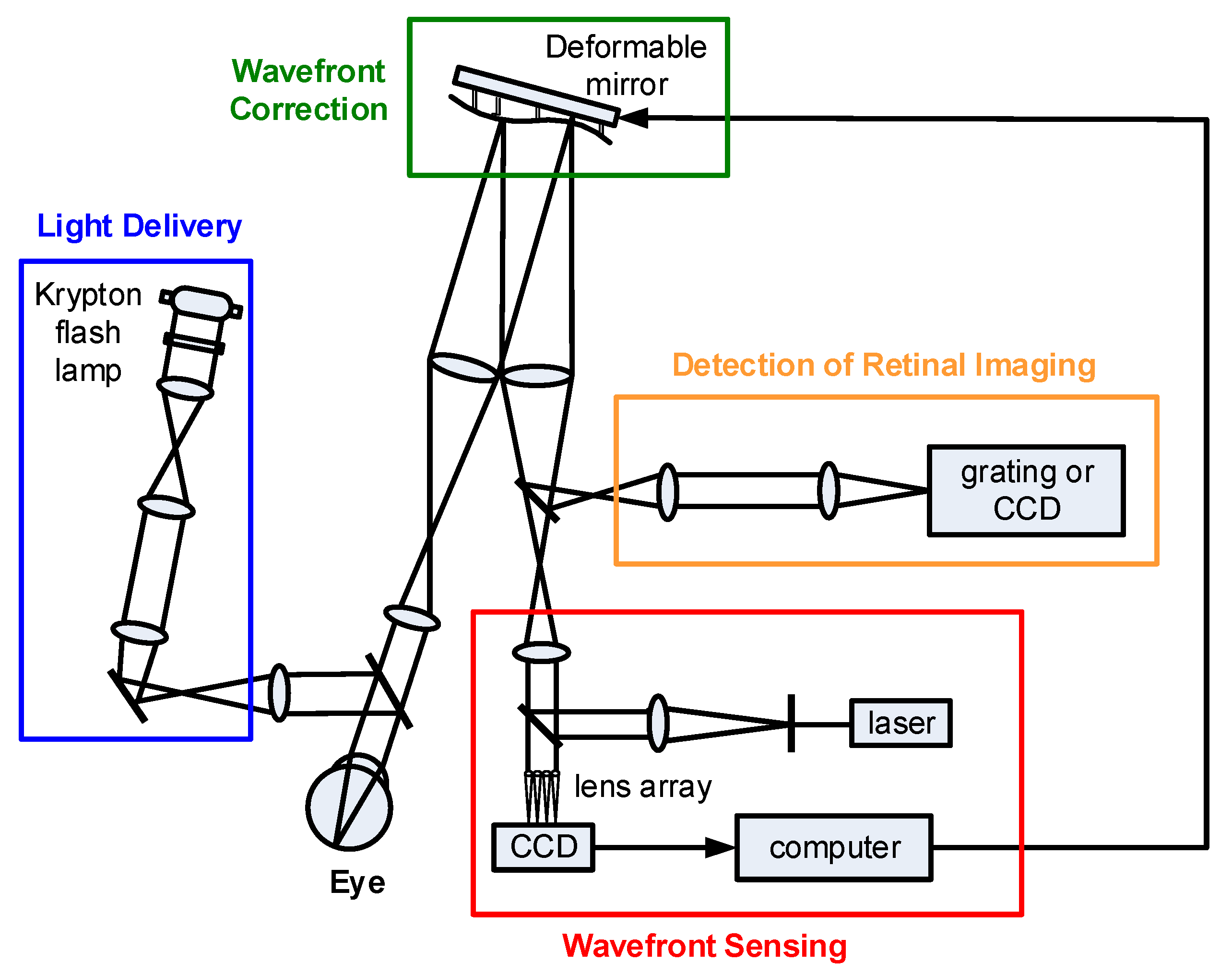
AO can measure and correct the dynamic aberrations of human eyes and improve the lateral resolution of retinal imaging. In 1997, the first AO-FC was developed in Williams’ lab at the University of Rochester [41], which used a krypton arc flash lamp to flood illuminate the retina, a SHWS to measure the eye’s wavefront aberration, a DM to correct the wavefront aberrations and a scientific-grade CCD to acquire images of the retina, as shown in Figure 3. This system was demonstrated with a lateral resolution of ~2 μm, which was close to the value of 1.9 μm expected from diffraction alone, enabling the imaging of microscopic structures as small as the size of single cells in the living human retina. However, AO-FC is limited by a low axial resolution (~300 μm), which reduces cone photoreceptor contrast and decreases repeatability of longitudinal cone density measurements [42,43].
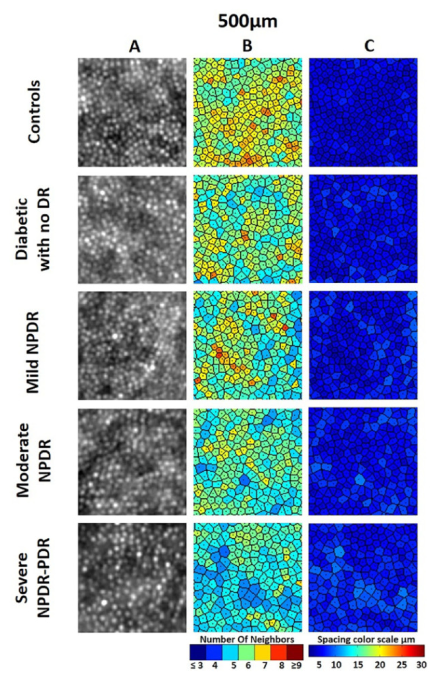
The spatial resolution, imaging field of view (FOV) and imaging speed of AO-FC are constantly improving [7,44,45]. On the basis of flood-illumination configuration, a commercially available AO-FC system, the RTX1 from Imagine Eyes (Orsay France), was developed and has been popularly used in retinal imaging for investigating parafoveal cone photoreceptors and retinal vasculature in normal subjects as well as eye diseases [46,47,48,49,50,51,52,53,54,55,56,57]. The RTX1 is based on a noncoherent flood-illuminated design with a central illumination wavelength of 850 nm, an FOV of 4 × 4° (1.2 × 1.2 mm on the retina), and a focusing range of 1600 μm that covers a retina thickness of ~300 μm, allowing for high-resolution (~2 μm) imaging of the retina. In 2012, Lombardo et al. [46] studied the variations in image optical quality of the eye and the sampling limit of resolution of the cone mosaic with axial length in young adults by using an RTX1 system. In 2015, Gocho et al. [48] reported the improvement of foveomacular cavities and spoke-wheel pattern retinoschisis observed by spectral-domain OCT (SD-OCT) and RTX1 AO-FC in a patient with X-linked retinoschisis (XLRS) treated with topical dorzolamide. AO images showed the detailed microstructure of spoke-wheel pattern foveoschisis and their improvement during a follow-up period, which was more helpful for clarifying the pathology of the foveoschisis in XLRS than with SD-OCT. In 2016, Soliman et al. [49] used an RTX1 AO-FC to assess cone density as a marker of early signs of retinopathy in patients with type II diabetes mellitus. It was found that in patients with type II diabetes, the loss of photoreceptors in AO images might be positively correlated with the severity of retinopathy, and the loss of photoreceptors was more obvious in patients with advanced retinopathy. Representative images of cone density, cone spacing, and Voronoi across study groups were shown in Figure 4. In 2018, Legras et al. [50] studied the distribution of cone density, spacing and arrangement in adult healthy retinas of 109 subjects at 2°, 3°, 4°, 5° and 6° of eccentricity along four meridians using an RTX1 AO-FC. In 2019, Markan et al. [51] used an RTX1 AO-FC to study photoreceptor changes after a successful macular hole surgery. They found the migration or shifting of cells from parafoveal retina toward the center that indicated the postoperative recovery of vision. In addition, the cells nearest to the hole margin (at 2° eccentricity) shifted more compared with cells that were further away. Nakamura et al. [52] used SD-OCT, fundus autofluorescence (FAF) imaging, and AO-FC to observe the long-term changes of retinal pigment epithelium (RPE) in the eyes of patients with Vogt-Koyanagi-Harada disease. SD-OCT and FAF could qualitatively study the thickness changes of the RPE layer, while high-resolution RTX1TM AO-FC was able to be used to quantitatively observe the improvements in the elevation or thickening of the RPE layer. In 2020, Potic et al. [54] used an RTX1 AO-FC to measure the change of photoreceptor density in patients with retinal detachment and studied its relationship with macular lesion. Ochinciuc et al. [55] analyzed cone density, cone mosaic, and FAF images in patients with focal laser-treated central serous chorioretinopathy (CSC). FAF and cone mosaic images were obtained in all patients with an RTX1 AO-FC. The results showed that the presence of hypoautofluorescent lesions and the duration of pathology were negative prognostic factors in CSC. In 2021, Cheng et al. [56] investigated the relationship between visual resolution and cone parameters in eyes with different levels of best corrected visual acuity (BCVA), and obtained the images of the cone photoreceptors at 1.5° from the fovea using an RTX1 AO-FC. The results showed that the greater cone density and smaller cone spacing at the parafovea were found in eyes with BCVA of 20/12.5 or better, as compared to that in eyes with BCVA of 20/16. In 2022, Baltă et al. [57] investigated the retinal microcirculation in diabetic patients using AO ophthalmoscopy (RTX1TM) and optical coherence tomography angiography (OCTA). The two techniques were demonstrated to provide complementary and useful information about the retinal microvasculature from early onset of diabetic disease.
In summary, AO-FC is an effective tool for studying the retinopathy of human eyes and has been widely applied in scientific experiments and clinical treatment to study color vision and cone classification [58,59], observe cone photoreceptors [46,50,51,53,54,56], image retinal vasculature [57,60], and track changes of cell groups [49,52], etc. AO imaging with a flood-illuminated system can acquire the entire retinal image in a relatively short time on the order of a few milliseconds, which minimizes the effect of eye movement. However, the entire frame is captured concurrently from backscattered light from the retina and choroid, which limits the axial resolution (~300 μm) of images and reduces the image contrast as compared to SLO-based systems [13].

3.2. Adaptive Optics Scanning Laser Ophthalmoscope (AO-SLO)

3.2.1. Basic Operation of AO-SLO

SLO was invented and developed in the 1980s by Webb et al. [61,62,63] and is widely regarded as an excellent choice for clinical imaging with superior contrast and resolution. Like a scanning laser microscope, the image in a SLO is generated over time by recording the scattered light from a focused spot as it is raster scanned across the region to be imaged. As such, it does not collect an image using a film or a CCD array. Instead, the intensity of each pixel is recorded using a more sensitive detector, such as photomultiplier tubes (PMT) or avalanche photodiodes (APD), and the location of each pixel is inferred by outputs from the scanning mirrors [64,65]. Compared to FCs, the SLOs are relatively insensitive to image degradation owing to scatter in the optics, and they also have the ability of optical sectioning in the retina, by employing a confocal pinhole conjugate to the retina. Similar to FCs, ocular aberration is a major limitation to the application range of SLOs.
With the combination of AO and SLO, AO-SLO can overcome the influence of wavefront aberrations and realize high resolution retinal imaging [66,67,68]. A simplified light path diagram for AO-SLO is shown in Figure 5 [64]. The AO-SLO system relays light from the laser source through a series of lenses and mirrors to the eye. An acousto-optic modulator (AOM) is used to modulate the laser beam to project patterns into the retina. The pupil is imaged onto the vertical scanner (VS), the horizontal scanner (HS), the DM and the SHWS lenslet array, and the Shack Hartman spot pattern is recorded by a CCD. Scatter light from the retina is detected by a PMT after passing through the confocal pinhole. When the confocal pinhole is optimized, the lateral and axial resolutions for a 6 mm pupil and 600 nm light are 1.9 μm and 33 μm, respectively. With larger pupils or shorter wavelengths, the resolution improves further. Owing to its confocal nature, AO-SLO is widely used for visualizing different layers within the retina such as photoreceptors, nerve fibers, retinal pigment epithelium [7]. In recent years, the performance of AO-SLO system, including resolution, field of view, and imaging speed, has been further improved.

3.2.2. Eye Tracking Integration into AO-SLO

The typical FOV of AO systems designed for human use is about 1~3° [41,66,69], which is consistent with the necessary image resolution/pixelation required to elucidate cones, microvasculature, and other structures at the cellular level. This design provides high magnification and can minimize system aberrations but restricts the identification of the exact retinal locus of the high-resolution view in relation to clinically observed changes. In an AO-SLO system, the small FOV is mainly limited by the human eye’s isoplanatic angle and the physical limits of its scanning mirrors and relay optics [70]. Moreover, eye motion is a major impediment to the efficient acquisition of high-resolution retinal images with AO-SLO. In 2010, Ferguson et al. [71] developed an AO-SLO by incorporating a wide-field line-scanning ophthalmoscope and a closed-loop optical retinal tracker. The wide-field imager and large-spherical-mirror optical interface design, as well as a large-stroke DM, enabled the AO-SLO image field to be corrected at any retinal coordinates of interest in a field of >25°. Eye tracking can significantly improve stable overlap and efficiency of sequential AO-SLO image capture by limiting the magnitude of eye movement excursions. In 2014, Yang et al. [72] implemented a robust closed-loop optical stabilization system with digital registration in one AO-SLO system. A 2-axis tip/tilt mirror was utilized for both slow scanning and optical stabilization. Closed-loop optical stabilization reduced the amplitude of eye-movement related-image motion by a factor of 10–15. Both optical stabilization and digital image registration synergistically corrected the residual eye motion with an accuracy of ~0.04–0.05 arcmin RMS (~0.20–0.25 μm) with typical fixational eye motion for normal observers. However, this approach failed in patients with poor fixation, because eye motion caused the FOV to drift substantially. Zhang et al. [73] solved this problem by tracking eye motion at multiple spatial scales by optically and electronically integrating a wide-FOV SLO (WF-SLO) with an AO-SLO. The multi-scale approach had a large stabilization range of ± 5.6° when implemented with fast tip/tilt mirrors, and the system was capable of reducing image motion by a factor of ~400, on average. The integrated WF-SLO and AO-SLO imaging system successfully addressed several major problems limiting the clinical utility of AO-SLO, including its small FOV, reliance on patient fixation for targeting imaging, and substantial post-processing time. In 2015, Sheehy et al. [74] built a system that combined a tracking SLO (TSLO) and an AO-SLO, resulting in both optical (hardware) and digital (software) eye-tracking capabilities. The hybrid system used the TSLO for active eye-tracking at a rate up to 960 Hz for real-time stabilization of the AO-SLO system; by correcting for high amplitude, low frequency drifts of the eye (RMS to an average of 0.06 arcmin), the active TSLO eye-tracking system enabled the AO-SLO system to capture high-resolution retinal images over a larger range of motion (FOV of 3.5° in experiments) than previously possible with just the AO-SLO imaging system alone.

3.2.3. Split Detection Approaches of AO-SLO

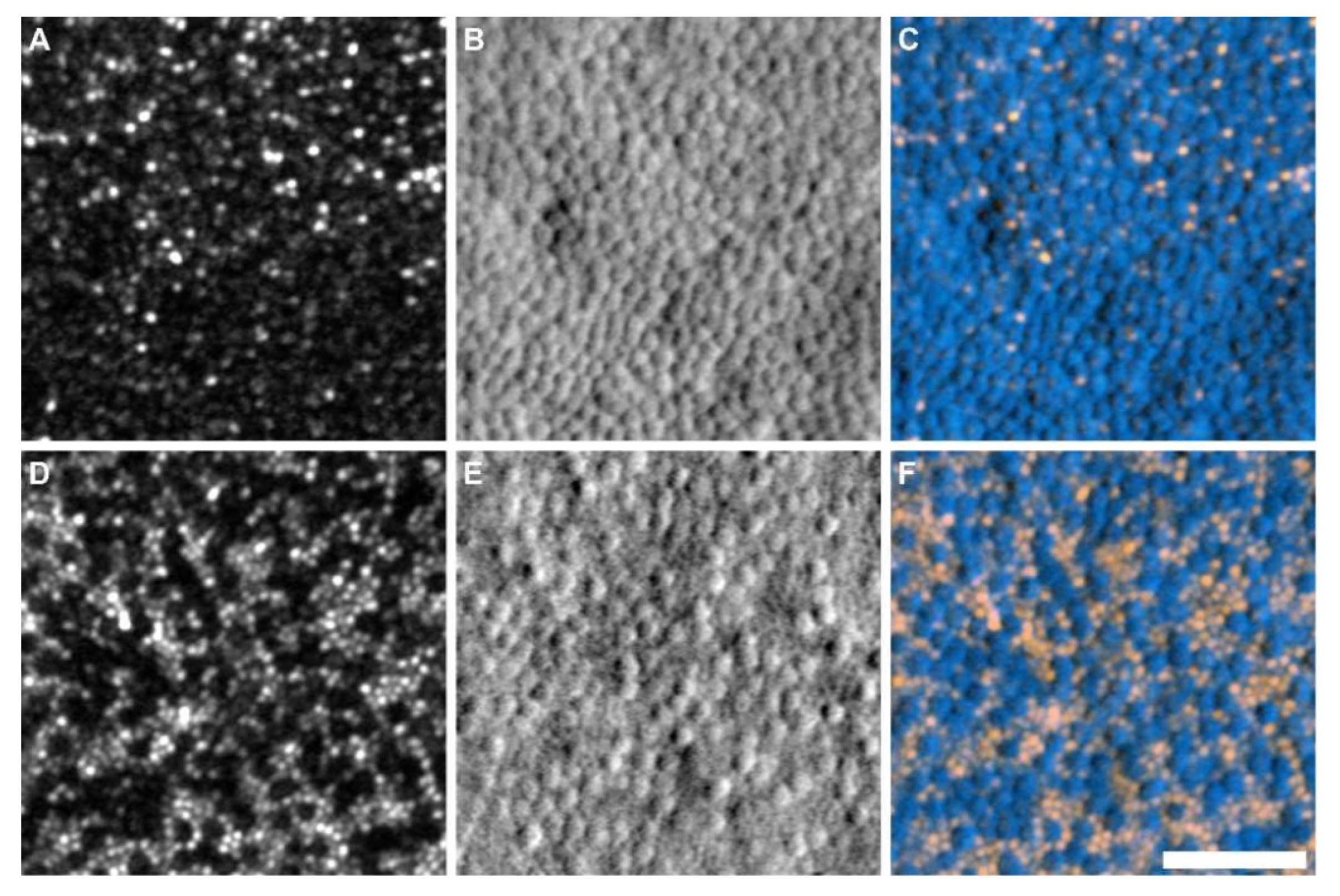
Recently, several non-confocal AO-SLO modalities have been developed, which collect scattered light surrounding the point of focus that is lost in confocal systems [75,76,77,78,79]. The utilization of multiple-scattered light photoreceptor imaging expanded rapidly and was investigated as a potential biomarker for therapeutic interventions in some hereditary retinal degenerations [80]. Non-confocal split-detector AO-SLO [77] employs two incoherent detectors to capture the equally-divided multiple-scattered light and has been proved to provide complementary information to that obtained from confocal AO-SLO [77,81,82,83,84]. In 2014, Scoles et al. [77] proposed and demonstrated a novel non-confocal split-detector AO-SLO technique for visualization of the cone photoreceptor mosaic. In that arrangement, the waveguided light from the photoreceptor outer segment (confocal) and the multiple-scattered light from the inner segment (split-detector) could be visualized simultaneously and in perfect spatial registration. Image sequences were collected at the center of the fovea and from 1° to 20° visual angle lateral (temporal) to fixation using a 1.0° and 1.5° square field of view. Figure 6 shows the confocal and split-detector AO-SLO images of the photoreceptor mosaic in a patient with achromatopsia at 0.4° and 2° from fixation. The results proved that split-detector imaging provided the first direct in vivo evidence of substantial remnant cone structure in patients with achromatopsia. Then, Sun et al. used confocal and non-confocal split-detector AO-SLO to examine cone photoreceptor structure in retinitis pigmentosa (RP) and Usher syndrome [81] and study photoreceptor disruption and vision loss associated with central serous retinopathy [82]. In 2019, Sajdak et al. [83] imaged the photoreceptor mosaic in the tree shrew retina in vivo and ex vivo. It was found that higher cone density was measured ex vivo compared with in vivo measurements. In 2021, Sredar et al. [84] recorded the quadrant reflectance confocal and non-confocal split-detector AO-SLO images of the photoreceptor mosaic in a subject with congenital achromatopsia (ACHM) and a normal control, by using various circular and annular apertures.

3.2.4. Handheld Designs of AO-SLO

The size and complexity of AO-SLO systems limit imaging to cooperative adult patients. To extend the application of AO-SLO to new patient populations, DuBose et al. [85] designed the first portable confocal handheld AOSLO (HAOSLO) system in 2018. By incorporating a novel computational wavefront sensorless AO algorithm and custom optics, the HAOSLO was miniaturized to weigh less than 200 g with dimensions of 10.3 cm × 5.3 cm × 14.4 cm, and it was used to image the cone photoreceptors in dilated supine young children and adult subjects. In 2020, Hagan et al. [86], from the same group, built the first compact and handheld multimodal (M-)HAOSLO (216 g, 12.3 cm × 5.3 cm × 14.4 cm) for simultaneous confocal and non-confocal split-detection (SD) imaging of cone photoreceptors in the human eye. The M-HAOSLO system allowed for more flexible and comprehensive patient data collection, which would be useful in acquiring high-resolution retinal images in clinical practice.

3.2.5. Algorithms and Applications of AO-SLO Retinal Imaging

Besides hardware correction, many data analysis approaches also play an important role in eliminating motion distortions and increasing the image signal-to-noise ratio (SNR). The image processing and data extraction steps for AO-SLO images, such as reference frame selection or identification of cone photoreceptor cells, often require some manual intervention, which is highly subjective and time consuming. Automated and semi-automated approaches for reference frame selection [87,88,89], motion extraction and registration [90,91], montaging [92], and cone localization [38,93,94,95] have been developed, which are of great significance for enhancing the performance of AO-SLO retinal imaging. Table 1 lists four typical algorithms that can improve the image resolution or imaging speed of the AO-SLO system. It should be noted that these retinal tracking and image registration algorithms are applicable to not only AO-SLO, but also other AO-based retinal imaging systems.
AO-SLO is an effective tool for studying the retinopathy of human eyes, and has been widely applied in scientific experiments and clinical treatment. The AO-SLO has allowed researchers to identify cone and rod photoreceptor cells [39,77,96,97,98], retinal pigment epithelial cells [99], retinal blood cells [100,101], retinal ganglion cells [78,102], and nerve fibers [67,103]. Moreover, the AO-SLO has been successfully used to detect and evaluate a variety of eye diseases, including central serous retinopathy [82], subretinal drusenoid deposits (SDD) [104,105], retinal vasculopathy [106], retinitis pigmentosa (RP) [81,107,108], glaucoma [109,110], idiopathic macular telangiectasia [111], diabetic retinopathy (DR) [112,113], hypertension retinopathy [114], acute zonal occult outer retinopathy (AZOOR) [115], cancer-associated retinopathy (CAR) [116], etc.
In summary, AO-SLO is a promising technology that can obtain high-resolution and high-contrast retinal images, as well as possessing optical sectioning capability. Various emerging technologies, such as introducing the eye tracking technique to compensate for the impact of eye motion on retinal imaging, using non-confocal split-detector imaging to provide complementary information for confocal AO-SLO, and replacing the point scanning with line scanning to reduce the complexity of the system and enhance the scanning speed, have been integrated to improve the imaging performances of AO-SLO. Moreover, many effective algorithms, including machine learning and deep learning, have been successfully used for AO-SLO-based data processing for further improving the image quality. To be industrialized and applied to the clinical practice, it still has high requirements for system miniaturization and low cost.

3.3. Adaptive Optics Optical Coherence Tomography (AO-OCT)

OCT was first demonstrated as a non-destructive retinal imaging tool in 1991 [1]. Because Fourier domain OCT (FD-OCT), which can be further divided into spectral domain OCT (SD-OCT) and swept source OCT (SS-OCT), can offer a significant advantage in acquisition speed without degradation of sensitivity and resolution compared to the time domain OCT (TD-OCT) technique, it became more prevalent in ophthalmology and has been clinically applied to evaluate retina, vitreous, choroid, optic nerve, etc. [117,118,119]. Benefiting from the unique features of the interferometric measurement method, the axial resolution of OCT is determined by the source bandwidth (BW), not the focusing optics. The high axial resolution (a few μm) enables OCT to visualize and characterize all the main cellular layers in the human retina. However, the lateral resolution of OCT in the eye is poor—typically no better than 15 μm—due to a small imaging pupil and the ocular aberrations.
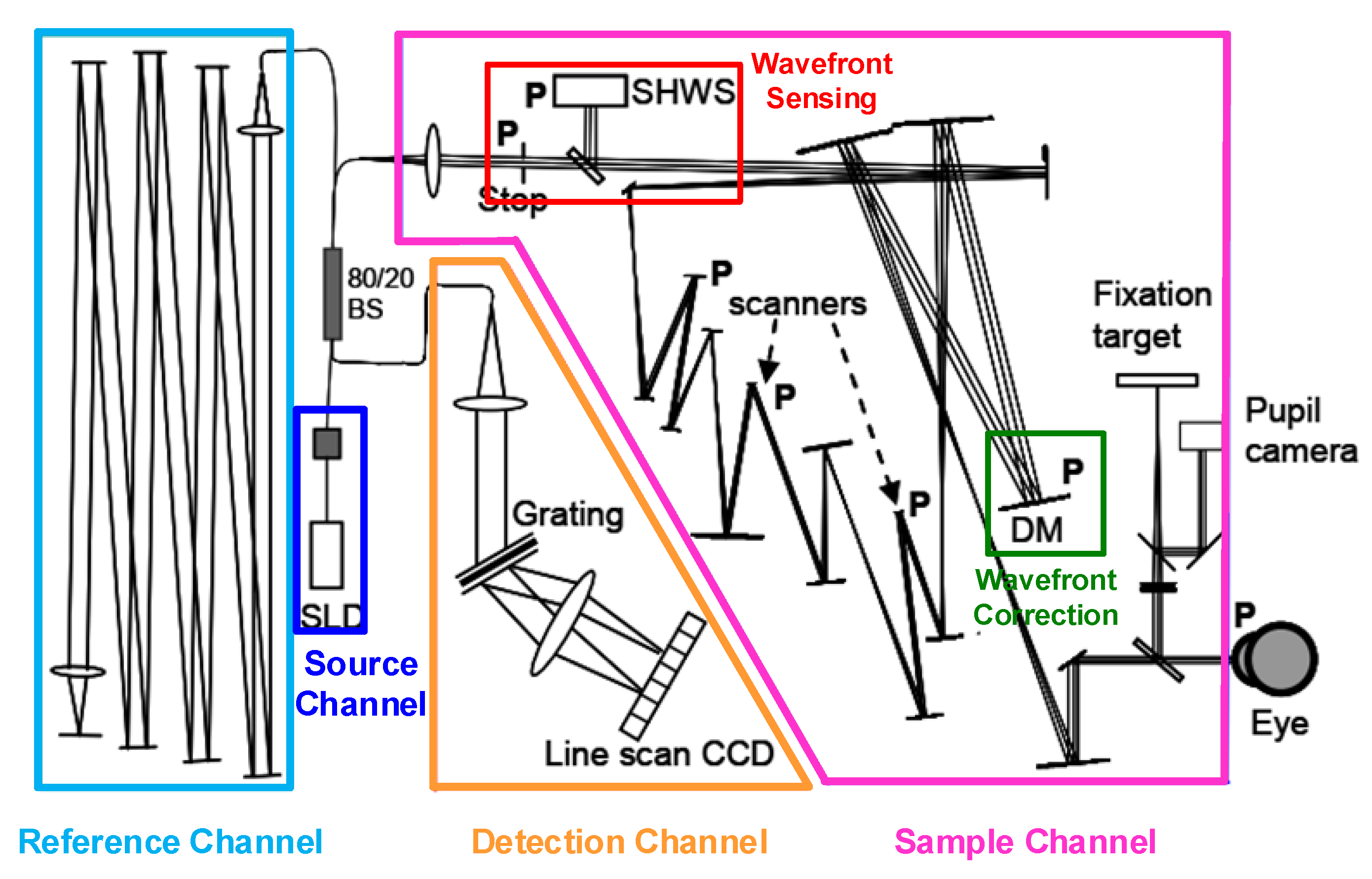
The combination of AO with OCT can improve the lateral resolution greatly and achieve high-resolution volumetric imaging, which makes it possible to visualize highly transparent cells and measure some of their internal processes within the retina. Moreover, AO-OCT could provide both optical amplitude and phase information [120]. The early attempts to implement AO correction in SD-OCT imaging were reported by Zhang et al. [121] and Zawadzki et al. [122], based on free space parallel SD-OCT and fiber-based SD-OCT, respectively. With dilated pupils >6 mm and distortion compensating AO as well as an improved axial resolution, these instruments could achieve lateral and axial resolutions up to 3 μm and 2~3 μm in the eye, respectively, which enabled the cellular level measurement [16]. A typical AO SD-OCT optical system was shown in Figure 7 [123] and it consisted of four modules: source channel, sample channel, reference channel, and detection channel. The illumination source was a broadband superluminescent diode (SLD). The AO system was integrated into the sample channel.
AO-OCT generally adopts a SHWS to measure the ocular aberrations directly and in real time [121,122,123]. However, various parameters, including the clinical situation, irregular pupil and retinal structure, high transparency of the eye, cataracts, and other factors, will affect the accuracy and reliability of the wavefront sensor data. Wavefront sensorless AO-OCT (SAO-OCT) does not rely on direct wavefront measurement, but depends on a depth-resolved image-driven optimization algorithm, which offers less system complexity compared with sensor-based AO design. Additionally, SAO-OCT does not need to define conjugate planes, which allows it to work reliably near non-planar retinal structures.
Numerous experiments have shown that SAO-OCT can be used to obtain retinal images with high resolution and high speed [19,20,34,37,124,125,126]. In 2015, Wong et al. [19] developed a SAO-OCT system for in vivo imaging of the photoreceptor layer in the human retina at several eccentricities. Due to SAO’s compensation, the photoreceptor visibility was improved, and the photoreceptor mosaic could be observed even at eccentricities as small as 1°. In 2017, Polans et al. [20,124] designed a wide-field (>70°) OCT combined with the SAO system, which was capable of acquiring aberration-corrected images without mosaicking. A fast SAO algorithm was employed to enable wavefront correction at the speed of individual B-scans (~20 ms) rather than volumes. Then, the system was used to enhance the visualization of anatomical and pathological features in the peripheral retina for neurologic diseases. In 2017, Reddikumar et al. [125] reported an SAO-OCT system with a 2.8-mm beam diameter and image-based optimization and a low-cost AO module containing a motorized Badal optometer for defocus correction and a liquid crystal device for vertical and oblique astigmatism correction. The system could achieve a lateral resolution of 11.5 μm over a width of at least 15° × 15°, and could correct the defocus ranging from −4.3 D to +4.3 D and vertical and oblique astigmatism ranging from −2.5 D to +2.5 D. In 2020, Camino et al. [126] built a SAO-OCTA instrument with an intermediate NA to produce depth-resolved angiograms with high lateral resolution and SNR over a 2 × 2 mm FOV and with a focal spot diameter of 6 μm. AO correction with the ability to optimize focusing at arbitrary retinal depths could be achieved in 1.35 s and the instrument could image the parafoveal circulation within 3 s.
CAO-OCT can correct optical aberrations and achieve volumetric aberration-free retinal imaging by numerically modifying the phase of the OCT data without the use of hardware AO components. In addition to lower cost and simpler system configurations, the post-processing nature of computational imaging also allows more flexible measurement and image improvement. CAO-OCT has been applied to in vivo imaging of the human retina [40,127,128,129]. South et al. [130] demonstrated a combined HAO and CAO system, achieving improved resolution as compared to HAO and improved SNR as compared to CAO. HAO + CAO may broaden the potential applications of computational imaging methods.
AO-OCT has been applied in normal and pathological retinal imaging for structural and functional measurements. The applications mainly include imaging or classification of photoreceptor [34,39,131], imaging and characterizing of RPE cells [132,133], imaging and quantifying of ganglion cells (GCs) [134] (as shown in Figure 8), imaging of macrophage distribution and dynamics [135], imaging and characterizing of lamina cribrosa within optic nerve head [136,137], retinopathy of prematurity [19], imaging of the outer layer of the retina in the macular area [20], visualization of retinal vessels [124], optic neuropathy [123], hereditary eye diseases, and the surgical treatment and follow-up of eye diseases.
Moreover, some approaches to improve versatility of AO-OCT have been reported, such as combing with polarization-sensitive OCT (PS-OCT) for more specific characteristics of tissue structure and function [138], and introducing reflective mirror-based line-scan to AO-OCT for high imaging speed [139,140].
In summary, AO-OCT can achieve 3D retinal images with high resolution and high speed, aberration corrected either by hardware or software, or both. It has played an extremely important role in promoting ophthalmic medicine, helping to visualize the microscopic morphology of the retinal structure, and allowing monitoring of disease progression or treatment.

3.4. Multimodal Adaptive Optics Retinal Imaging Techniques

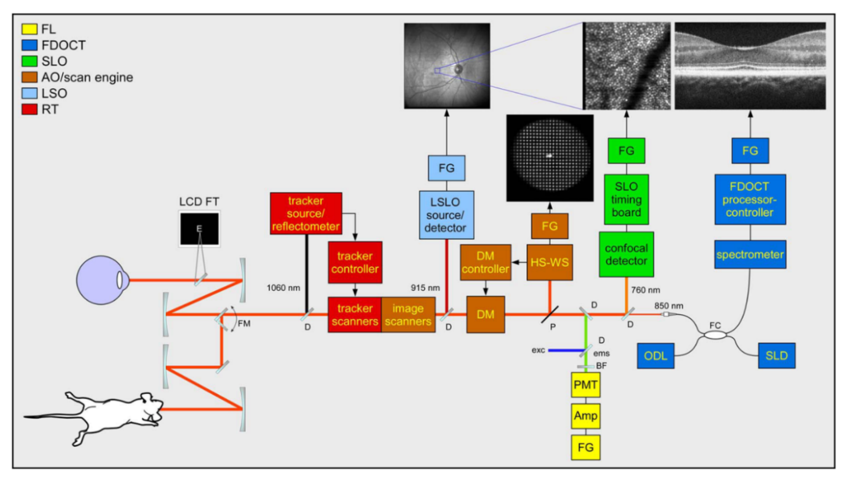
AO-based multimodal retinal imaging can provide complementary information and enable resolution of various cell types for retinal depth imaging, and is of great clinical relevance, since microscopic retinal structures become visible in living human eyes [105,141,142,143,144,145,146,147,148,149,150,151]. Multimodal AO systems integrating AO-SLO and AO-OCT were first developed for retinal imaging by the groups led by Zawadzki [141] and Hammer [142,143], respectively. Both of them used FD-OCT, but with variations of SD-OCT and SS-OCT, respectively. The former could acquire OCT and SLO in vivo images of the human retina at ≤3.5 μm lateral resolution (~840 nm (110 nm BW) for OCT and ~680 nm (10 nm BW) for SLO, ~6.7 mm pupil diameter). The latter were capable of collecting AO enhanced SLO images to resolve cones within 0.5° of the fovea and AO enhanced OCT images with improved penetration for identification of all major retinal layers (~1070 nm (79 nm BW) for OCT, ~750 nm (14 nm BW) for SLO, ~830 nm (26 nm BW) for LSO and ~915 nm for retinal tracking (RT) beams). Figure 9 shows the schematic diagram of the multimodal AO system [142,143]; its output included SLO, OCT, LSO, and HSWS videos, and its performance was tested on human subjects and rodents. In 2013, Meadway et al. [144] developed a dual-mode AO-based retinal imaging system that combined SLO and OCT. The two imaging modes were switched by a flip mirror (FM). The system demonstrated the in vivo images from healthy and diseased retinas, and then it was used to study microstructure of subretinal drusenoid deposits [105]. In 2016, Salas et al. [146] proposed a compact multimodal imaging prototype combining AO-FC and AO-OCT in a single instrument. AO-FC was able to obtain AO fundus images with a FOV of 4 × 4° and a frame rate of 10 fps. In AO-OCT mode, the imaging speed was 200 kHz A-scan rate, and the lateral and axial resolutions were 4 µm and 5 µm, respectively. Hafner et al. (in 2018) [147] and Karst et al. (in 2019) [148] reported the integration of AO-FC and AO-OCT, where the AO-OCT prototype was incorporated into an RTX1 AO-FC. They studied the dynamic changes and analyzed 3D morphological details of retinal microaneurysms in diabetes, respectively. In 2018, Liu et al. [149] presented a novel multimodal AO (mAO) system that combined two complementary approaches, AO-SLO and AO-OCT, in one instrument with flexible alternation of scanning modes and independent focus control. The mAO system’s imaging performance was demonstrated through the visualization of cells in their mosaic arrangement across the full depth of the retina in three human subjects. In 2019, Wahl et al. [150] proposed a multimodal sensorless AO en-face retina imaging system composed of OCT, OCTA, confocal SLO and fluorescence detection. The system performance was studied by observation of dynamics of microglial cell branching and volumetric cellular imaging of microglia throughout the inner retina on wild type mice and transgenic mice with GFP-labeled cells. In 2021, Bower et al. [151] developed an imaging platform combining multimodal AO-SLO with AO-OCT for visualization of the human retinal pigment epithelial mosaic. The results showed that by combining information from all modalities, inferences about normal vs. disrupted cellular structure could be validated, thus improving the reliability, accuracy, and overall consistency of in vivo assessment of the human RPE mosaic.
In summary, multimodal AO retinal imaging is a powerful tool for capturing images of the retina. Extraction of information from retinal cells is optimal when their optical properties, structure, and physiology are matched to the unique capabilities of each imaging modality, which indicates the great clinical potential of multimodal AO retinal imaging for early diagnosis and treatment of eye disease.

4. Summary and Prospects

The eye is not only a window to the mind, but also a reflection of the health state of the body. Retinal diseases, which can cause vision loss and even blindness, have become one of the main causes of blindness and attracted extensive attention from many experts and scholars. Moreover, some retinopathy symptoms are related to human diseases, such as diabetes, tumor and kidney disease, etc. Therefore, it is of great significance to realize retinal imaging with high resolution and high speed. However, the aberrations of living human eyes show obvious individual differences and change with time; therefore, it is difficult to obtain retinal images at the cellular level using traditional clinical methods.
AO is used for real-time aberration compensation to improve image or beam quality in an optical system with dynamic aberrations. The use of AO-based optical imaging in ophthalmology has greatly changed the way we observe the human eye both at the cellular and metabolic level. By correcting the individual optical aberrations, AO offers a lateral resolution of ~2 μm, which is unachievable for traditional retinal imaging techniques (lateral resolution: ~10–15 μm). Therefore AO-based retinal imaging technology not only enables scientists to resolve fine retinal structures but also improves the clinical interventions for different eye diseases. By exploiting flood-illumination and CCD detection, AO-FC provides a direct and effective method for imaging the retina and diagnosing fundus diseases, and can help doctors to determine the treatment plan in time; however, its axial resolution (~300 μm) and image contrast are relatively poor due to the backscattered light from the retina and choroid. AO-SLO can obtain retinal images at the cellular level and in different retinal layers with an axial resolution of tens of microns by employing a confocal pinhole conjugate to the retina. AO-OCT not only inherits the advantages of OCT technology, such as non-invasiveness, depth-resolved cross-sectional imaging, high sensitivity, and detection speed, but can also provide a high-resolution 3D image (both lateral and axial resolution on the order of a few microns) of the retinal microstructures. The combination of multiple AO modalities increases the complexity of the optical system, but can provide complementary and optimal information for retinal imaging; multimodal AO shows great potential for clinical use.
At present, AO retinal imaging technology is not yet fully mature, and the relevant instruments and equipment are still in the process of design and development, and more exploration and experiments are needed before they can be applied in clinical ophthalmology. Meanwhile, the instruments and equipment are always expensive, and operators are required to have excellent skills and data processing capabilities. These characteristics make it challenging to popularize these systems in clinical ophthalmology. In the future, the application of AO in ophthalmic medicine may have the following development trends: (1) Miniaturization. The equipment in the laboratory stage is often large, which brings a lot of inconvenience in clinical use. Since sensors, calibrators, and other devices are becoming smaller and lighter, AO-based devices are expected to develop towards higher integration and smaller volume. (2) Low costs. Expensive systems will increase the burden of patients. With the increasing maturity of AO technology, the costs of mass production will be decreased, which will promote clinical applications. (3) Easy operation. The future systems will use highly integrated designs and provide user-friendly software, allowing doctors and nurses to operate it without much professional knowledge. (4) High resolution. High resolution has always been the pursuit of imaging systems. Although the introduction of AO has greatly improved the resolution of the system, there are still many restricting factors, such as the low spatial resolution and limited dynamic range of SHWS. In the future, the resolution of the system is expected to be further improved by the advances of hardware and software. (5) Multi-modality. Different types of ophthalmic imaging methods can obtain complementary information about the fundus tissues related to different aspects and levels. For example, the multi-mode system composed of OCT and SLO can quickly locate the target and simultaneously achieve retinal structure and function imaging, which meets the requirements of rapid and high accuracy in clinical imaging. (6) From structure to function. Changes in the structure and function of retinal cells may serve as sensitive biomarkers of disease onset. While in vivo studies focus on structural changes, functional ones may better capture cell health because they have more direct connection to cell physiology. Cell distribution, motility and changes are potentially sensitive indicators of cell health. In the future, AO-based retinal imaging approaches are to be applied in developing novel disease biomarkers and exploring new pathways in disease progression.
In summary, the application of AO in ophthalmology will inevitably become one of the important means to help doctors to explore the pathogenesis of various eye diseases and to follow up patients, and play a positive role in promoting the development of innovative devices and treatment procedures in refractive surgery and retinal diagnostics.

Author Contributions

Conceptualization, L.L. and P.G.; Methodology, L.L. and Z.W.; Writing—Original Draft Preparation, L.L., Z.W. and M.Q.; Writing—Review and Editing, L.L., Z.W., M.Q., Y.L., M.Z. and D.L.; Supervision, L.L. and P.G.; Funding Acquisition, L.L. and P.G. All authors have read and agreed to the published version of the manuscript.

Funding

This work was funded by the 111 Project (B17035), the National Natural Science Foundation of China (62075177), the Open Research Fund of CAS Key Laboratory of Spectral Imaging Technology (LSIT202005W).

Conflicts of Interest

The authors declare no conflict of interest.

References

  1. Huang, D.; Swanson, E.A.; Lin, C.P.; Schuman, J.S.; Stinson, W.G.; Chang, W.; Hee, M.R.; Flotte, T.; Gregory, K.; Puliafito, G.A.; et al. Optical coherence tomography. Science 1991, 254, 1178–1181. [Google Scholar] [CrossRef] [PubMed] [Green Version]
  2. Miller, D.T.; Williams, D.R.; Morris, G.M.; Liang, J. Images of cone photoreceptors in the living human eye. Vis. Res. 1996, 36, 1067–1079. [Google Scholar] [CrossRef] [Green Version]
  3. Wade, A.; Fitzke, F. A fast, robust pattern recognition system for low light level image registration and its application to retinal imaging. Opt. Express 1998, 3, 190–197. [Google Scholar] [CrossRef] [PubMed]
  4. Babcock, H.W. The possibility of compensating astronomical seeing. Publ. Astron. Soc. Pac. 1953, 65, 229–236. [Google Scholar] [CrossRef]
  5. Liang, J.; Grimm, B.; Goelz, S.; Bille, J.F. Objective measurement of wave aberrations of the human eye with the use of a Hartmann–Shack wave-front sensor. J. Opt. Soc. Am. A 1994, 11, 1949–1957. [Google Scholar] [CrossRef]
  6. Clarkson, D. Adaptive optics in ophthalmology-Emergence of diagnostic tools. Optician 2007, 234, 38–39. [Google Scholar]
  7. Godara, P.; Dubis, A.M.; Roorda, A.; Duncan, J.L.; Carroll, J. Adaptive optics retinal imaging: Emerging clinical applications. Optom. Vis. Sci. 2010, 87, 930–941. [Google Scholar] [CrossRef] [Green Version]
  8. Burns, S.A.; Elsner, A.E.; Sapoznik, K.A.; Warner, R.L.; Gast, T.J. Adaptive optics imaging of the human retina. Prog. Retin. Eye Res. 2019, 68, 1–30. [Google Scholar] [CrossRef]
  9. Gill, J.S.; Moosajee, M.; Dubis, A.M. Cellular imaging of inherited retinal diseases using adaptive optics. Eye 2019, 33, 1683–1698. [Google Scholar] [CrossRef]
  10. Bedggood, P.; Metha, A. Adaptive optics imaging of the retinal microvasculature. Clin. Exp. Optom. 2020, 103, 112–122. [Google Scholar] [CrossRef] [PubMed]
  11. Porter, J.; Guirao, A.; Cox, I.G.; Williams, D.R. Monochromatic aberrations of the human eye in a large population. J. Opt. Soc. Am. A Opt. Image Sci. Vis. 2001, 18, 1793–1803. [Google Scholar] [CrossRef] [PubMed] [Green Version]
  12. Bille, J.F. High Resolution Imaging in Microscopy and Ophthalmology; Springer: Cham, Switzerland, 2019. [Google Scholar]
  13. Akyol, E.; Hagag, A.M.; Sivaprasad, S.; Lotery, A.J. Adaptive optics: Principles and applications in ophthalmology. Eye 2021, 35, 244–264. [Google Scholar] [CrossRef] [PubMed]
  14. Kozak, I. Retinal imaging using adaptive optics technology. Saudi J. Ophthalmol. 2014, 28, 117–122. [Google Scholar] [CrossRef] [PubMed] [Green Version]
  15. Hampson, K.M.; Turcotte, R.; Miller, D.T.; Kurokawa, K.; Males, J.R.; Ji, N.; Booth, M.J. Adaptive optics for high-resolution imaging. Nat. Rev. Methods Primers 2021, 1, 68. [Google Scholar] [CrossRef]
  16. Roorda, A. Adaptive optics for studying visual function: A comprehensive review. J. Vis. 2011, 11, 6. [Google Scholar] [CrossRef]
  17. Hofer, H.; Sredar, N.; Queener, H.; Li, C.; Porter, J. Wavefront sensorless adaptive optics ophthalmoscopy in the human eye. Opt. Express 2011, 19, 14160–14171. [Google Scholar] [CrossRef]
  18. Wen, L.; Yang, P.; Wang, S.; Liu, W.; Chen, S.; Xu, B. A high speed model-based approach for wavefront sensorless adaptive optics systems. Opt. Laser Technol. 2018, 99, 124–132. [Google Scholar]
  19. Wong, K.S.K.; Jian, Y.F.; Cua, M.; Bonora, S.; Zawadzki, R.J.; Sarunic, M.V. In vivo imaging of human photoreceptor mosaic with wavefront sensorless adaptive optics optical coherence tomography. Biomed. Opt. Express 2015, 6, 580–590. [Google Scholar] [CrossRef] [Green Version]
  20. Polans, J.; Keller, B.; Carrasco-Zevallos, O.M.; LaRocca, F.; Cole, E.; Whitson, H.E.; Lad, E.M.; Farsiu, S.; Izatt, J.A. Wide-field retinal optical coherence tomography with wavefront sensorless adaptive optics for enhanced imaging of targeted regions. Biomed. Opt. Express 2017, 8, 16–37. [Google Scholar] [CrossRef] [Green Version]
  21. Zhou, X.L.; Bedggood, P.; Bui, B.; Nguyen, C.T.O.; He, Z.; Metha, A. Contrast-based sensorless adaptive optics for retinal imaging. Biomed. Opt. Express 2015, 6, 3577–3595. [Google Scholar] [CrossRef] [Green Version]
  22. Adie, S.G.; Graf, B.W.; Ahmad, A.; Carney, P.S.; Boppart, S.A. Computational adaptive optics for broadband optical interferometric tomography of biological tissue. Proc. Natl. Acad. Sci. USA 2012, 109, 7175–7180. [Google Scholar] [CrossRef] [PubMed] [Green Version]
  23. Liu, Y.-Z.; Shemonski, N.D.; Adie, S.G.; Ahmad, A.; Bower, A.J.; Carney, P.S.; Boppart, S.A. Computed optical interferometric tomography for high-speed volumetric cellular imaging. Biomed. Opt. Express 2014, 5, 2988–3000. [Google Scholar] [CrossRef] [PubMed] [Green Version]
  24. South, F.A.; Liu, Y.-Z.; Bower, A.J.; Xu, Y.; Carney, P.S.; Boppart, S.A. Wavefront measurement using computational adaptive optics. J. Opt. Soc. Am. A Opt. Image Sci. Vis. 2018, 35, 466–473. [Google Scholar] [CrossRef]
  25. Liu, Y.-Z.; South, F.A.; Xu, Y.; Carney, P.S.; Boppart, S.A. Computational optical coherence tomography [invited]. Biomed. Opt. Express 2017, 8, 1549–1574. [Google Scholar] [CrossRef] [PubMed] [Green Version]
  26. Booth, M.J. Adaptive optics in microscopy. Philos. Transact. A Math. Phys. Eng. Sci. 2007, 365, 2829–2843. [Google Scholar] [CrossRef] [PubMed]
  27. Zommer, S.; Ribak, E.N.; Lipson, S.G.; Adler, J. Simulated annealing in ocular adaptive optics. Opt. Lett. 2006, 31, 939–941. [Google Scholar] [CrossRef]
  28. Vorontsov, M.A. Decoupled stochastic parallel gradient descent optimization for adaptive optics: Integrated approach for wave-front sensor information fusion. J. Opt. Soc. Am. A 2002, 19, 356–368. [Google Scholar] [CrossRef]
  29. Huang, L.; Rao, C. Wavefront sensorless adaptive optics: A general model-based approach. Opt. Express 2011, 19, 371–379. [Google Scholar]
  30. Liu, Y.; Ma, J.; Li, B.; Chu, J. Hill-climbing algorithm based on Zernike modes for wavefront sensorless adaptive optics. Opt. Eng. 2013, 52, 016601. [Google Scholar] [CrossRef]
  31. Yang, Q.; Zhao, J.; Wang, M.; Jia, J. Wavefront sensorless adaptive optics based on the trust region method. Opt. Lett. 2015, 40, 1235–1237. [Google Scholar] [CrossRef]
  32. Jian, Y.; Lee, S.; Ju, M.; Heisler, M.; Ding, W.; Zawadzki, R.; Bonora, S.; Sarunic, M. Lens-based wavefront sensorless adaptive optics swept source OCT. Sci. Rep. 2015, 6, 27620. [Google Scholar] [CrossRef] [PubMed] [Green Version]
  33. Camino, A.; Ng, R.; Huang, J.; Guo, Y.; Ni, S.; Jia, Y.; Huang, D.; Jian, Y. Depth-resolved optimization of real-time sensorless adaptive optics optical coherence tomography. Opt. Lett. 2020, 45, 2612–2615. [Google Scholar] [CrossRef] [PubMed]
  34. Verstraete, H.R.G.W.; Heisler, M.; Ju, M.J.; Wahl, D.; Bliek, L.; Kalkman, J.; Bonora, S.; Jian, Y.; Verhaegen, M.; Sarunic, M.V. Wavefront sensorless adaptive optics OCT with the DONE algorithm for in vivo human retinal imaging. Biomed. Opt. Express 2017, 8, 2261–2275. [Google Scholar] [CrossRef] [PubMed] [Green Version]
  35. Xu, Z.; Yang, P.; Hu, K.; Xu, B.; Li, H. Deep learning control model for adaptive optics systems. Appl. Opt. 2019, 58, 1998–2009. [Google Scholar] [CrossRef] [PubMed] [Green Version]
  36. Hu, K.; Xu, B.; Xu, Z.; Wen, L.; Yang, P.; Wang, S.; Dong, L. Self-learning control for wavefront sensorless adaptive optics system through deep reinforcement learning. Optik 2019, 178, 785–793. [Google Scholar]
  37. Durech, E.; Newberry, W.; Franke, J.; Sarunic, M. Wavefront sensor-less adaptive optics using deep reinforcement learning. Biomed. Opt. Express 2021, 12, 5423–5438. [Google Scholar] [CrossRef] [PubMed]
  38. Cunefare, D.; Langlo, C.S.; Patterson, E.J.; Blau, S.; Dubra, A.; Carroll, J.; Farsiu, S. Deep learning based detection of cone photoreceptors with multimodal adaptive optics scanning light ophthalmoscope images of achromatopsia. Biomed. Opt. Express 2018, 9, 3740–3756. [Google Scholar] [CrossRef]
  39. Cunefare, D.; Huckenpahler, A.L.; Patterson, E.J.; Dubra, A.; Farsiu, S. RAC-CNN: Multimodal deep learning based automatic detection and classification of rod and cone photoreceptors in adaptive optics scanning light ophthalmoscope images. Biomed. Opt. Express 2019, 10, 3815–3832. [Google Scholar] [CrossRef]
  40. Zhu, D.; Wang, R.; Žurauskas, M.; Pande, P.; Bi, J.; Yuan, Q.; Wang, L.; Gao, Z.; Boppart, S.A. Automated fast computational adaptive optics for optical coherence tomography based on a stochastic parallel gradient descent algorithm. Opt. Express 2020, 28, 23306–23319. [Google Scholar] [CrossRef]
  41. Liang, J.; Williams, D.R.; Miller, D.T. Supernormal vision and high-resolution retinal imaging through adaptive optics. J. Opt. Soc. Am. A 1997, 14, 2884–2892. [Google Scholar] [CrossRef] [Green Version]
  42. Chew, A.L.; Sampson, D.M.; Kashani, I.; Chen, F.K. Agreement in cone density derived from gaze-directed single images versus wide-field montage using adaptive optics flood illumination ophthalmoscopy. Transl. Vis. Sci. Technol. 2017, 6, 9. [Google Scholar] [CrossRef] [PubMed] [Green Version]
  43. Feng, S.; Gale, M.J.; Fay, J.D.; Faridi, A.; Titus, H.E.; Garg, A.K.; Michaels, K.V.; Erker, L.R.; Peters, D.; Smith, T.B.; et al. Assessment of different sampling methods for measuring and representing macular cone density using flood-illuminated adaptive optics. Investig. Ophth. Vis. Sci. 2015, 56, 5751–5763. [Google Scholar] [CrossRef] [PubMed] [Green Version]
  44. Rha, J.; Jonnal, R.S.; Thorn, K.E.; Qu, J.; Zhang, Y.; Miller, D.T. Adaptive optics flood-illumination camera for high speed retinal imaging. Opt. Express 2006, 14, 4552–4569. [Google Scholar] [CrossRef]
  45. Yamaguchi, T.; Nakazawa, N.; Bessho, K.; Kitaguchi, Y.; Maeda, N.; Fujikado, T.; Mihashi, T. Adaptive optics fundus camera using a liquid crystal phase modulator. Opt. Rev. 2008, 15, 173–180. [Google Scholar] [CrossRef]
  46. Lombardo, M.; Serrao, S.; Ducoli, P.; Lombardo, G. Variations in image optical quality of the eye and the sampling limit of resolution of the cone mosaic with axial length in young adults. J. Cataract. Refr. Surg. 2012, 38, 1147–1155. [Google Scholar] [CrossRef] [PubMed]
  47. Hayashi, A.; Nakamura, T.; Otsuka, M.; Miyakoshi, A.; Oiwake, T.; Ueda, T. Observation of microcystic changes in the inner retina with adaptive optics fundus camera. Investig. Ophth. Vis. Sci. 2014, 55, 2608. [Google Scholar]
  48. Gocho, K.; Akeo, K.; Kameya, S.; Yamaki, K.; Mizota, A.; Takahashi, H. The improvement of Spoke-Wheel pattern foveoschisis in a patient with X-linked retinoschisis treated with topical dorzolamide observed by high-resolution adaptive optics camera. Acta Ophthalmol. 2015, 93, ABS15-0537. [Google Scholar] [CrossRef]
  49. Soliman, M.K.; Sadiq, M.A.; Agarwal, A.; Sarwar, S.; Hassan, M.; Hanout, M.; Graf, F.; High, R.; Do, D.V.; Nguyen, Q.D.; et al. High-resolution imaging of parafoveal cones in different stages of diabetic retinopathy using adaptive optics fundus camera. PLoS ONE 2016, 11, e0152788. [Google Scholar] [CrossRef]
  50. Legras, R.; Gaudric, A.; Woog, K. Distribution of cone density, spacing and arrangement in adult healthy retinas with adaptive optics flood illumination. PLoS ONE 2018, 13, e0191141. [Google Scholar] [CrossRef] [PubMed]
  51. Markan, A.; Chawla, R.; Gupta, V.; Tripathi, M.; Sharma, A.; Kumar, A. Photoreceptor evaluation after successful macular hole closure: An adaptive optics study. Ther. Adv. Ophthalmol. 2019, 11, 251–258. [Google Scholar] [CrossRef]
  52. Nakamura, T.; Hayashi, A.; Oiwake, T. Long-term changes of retinal pigment epithelium in the eyes with Vogt-Koyanagi-Harada disease observed by adaptive optics imaging. Clin. Ophthalmol. 2019, 13, 927–933. [Google Scholar] [CrossRef] [PubMed] [Green Version]
  53. Ueda-Consolvo, T.; Ozaki, H.; Nakamura, T.; Oiwake, T.; Hayashi, A. The association between cone density and visual function in the macula of patients with retinitis pigmentosa. Graef. Arch. Clin. Exp. 2019, 257, 1841–1846. [Google Scholar] [CrossRef] [PubMed]
  54. Potic, J.; Bergin, C.; Giacuzzo, C.; Daruich, A.; Pournaras, J.A.; Kowalczuk, L.; Behar-Cohen, F.; Konstantinidis, L.; Wolfensberger, T.J. Changes in visual acuity and photoreceptor density using adaptive optics after retinal detachment repair. Retina 2020, 40, 376–386. [Google Scholar] [CrossRef]
  55. Ochinciuc, R.; Ochinciuc, U.; Stanca, H.T.; Barac, R.; Darabus, D.; Suta, M.; Balta, F.; Burcea, M. Photoreceptor assessment in focal laser-treated central serous chorioretinopathy using adaptive optics and fundus autofluorescence. Medicine 2020, 99, 195–236. [Google Scholar] [CrossRef] [PubMed]
  56. Cheng, H.; Ciuffreda, K.J.; Jiang, H.; Zhou, K.; Lin, S.; Zheng, J.; Yu, X.; Vasudevan, B.; Liang, Y. Cone parameters in different vision levels from the adaptive optics imaging. Medicine 2021, 100, e25618. [Google Scholar] [CrossRef] [PubMed]
  57. Baltă, F.; Cristescu, I.-E.; Mirescu, A.-E.; Baltă, G.; Zemba, M.; Tofolean, I.T. Investigation of retinal microcirculation in diabetic patients using adaptive optics ophthalmoscopy and optical coherence angiography. J. Diabetes Res. 2022, 2022, 1516668. [Google Scholar] [CrossRef]
  58. Roorda, A.; Williams, D. The arrangement of the three cone classes in the living human eye. Nature 1999, 397, 520–522. [Google Scholar] [CrossRef]
  59. Wagner-Schuman, M.; Neitz, J.; Rha, J.; Williams, D.R.; Neitz, M.; Carroll, J. Color-deficient cone mosaics associated with Xq28 opsin mutations: A stop codon versus gene deletions. Vis. Res. 2010, 50, 2396–2402. [Google Scholar] [CrossRef] [Green Version]
  60. Koch, E.; Rosenbaum, D.; Brolly, A.; Sahel, J.A.; Chaumet-Riffaud, P.; Girerd, X.; Rossant, F.; Paques, M. Morphometric analysis of small arteries in the human retina using adaptive optics imaging: Relationship with blood pressure and focal vascular changes. J. Hypertens. 2014, 32, 890–898. [Google Scholar] [CrossRef] [Green Version]
  61. Webb, R.H.; Hughes, G.W.; Pomerantzeff, O. Flying spot TV ophthalmoscope. Appl. Opt. 1980, 19, 2991–2997. [Google Scholar] [CrossRef]
  62. Webb, R.H.; Hughes, G.W. Scanning laser ophthalmoscope. IEEE Trans. Biomed. Eng. 1981, 28, 4884492. [Google Scholar] [CrossRef] [PubMed]
  63. Webb, R.H.; Hughes, G.W.; Delori, F.C. Confocal scanning laser ophthalmoscope. Appl. Opt. 1987, 26, 1492–1499. [Google Scholar] [CrossRef] [PubMed]
  64. Roorda, A. Applications of adaptive optics scanning laser ophthalmoscopy. Optom. Vis. Sci. 2010, 87, 260–268. [Google Scholar] [CrossRef] [Green Version]
  65. Dreher, A.W.; Bille, J.F.; Weinreb, R.N. Active optical depth resolution improvement of the laser tomographic scanner. Appl. Opt. 1989, 28, 804–808. [Google Scholar] [CrossRef] [PubMed]
  66. Roorda, A.; Romero-Borja, F.; Donnelly, W., III; Queener, H.; Hebert, T.J.; Campbell, M.C.W. Adaptive optics scanning laser ophthalmoscopy. Opt. Express 2002, 10, 405–412. [Google Scholar] [CrossRef]
  67. Takayama, K.; Ooto, S.; Hangai, M.; Arakawa, N.; Oshima, S.; Shibata, N.; Hanebuchi, M.; Inoue, T.; Yoshimura, N. High-resolution imaging of the retinal nerve fiber layer in normal eyes using adaptive optics scanning laser ophthalmoscopy. PLoS ONE 2012, 7, e33158. [Google Scholar] [CrossRef] [PubMed]
  68. Venkateswaran, K.; Roorda, A.; Romero-Borja, F. Theoretical modeling and evaluation of the axial resolution of the adaptive optics scanning laser ophthalmoscope. J. Biomed. Opt. 2004, 9, 132–138. [Google Scholar] [CrossRef]
  69. Gómez-Vieyra, A.; Dubra, A.; Malacara-Hernández, D.; Williams, D.R. First-order design of off-axis reflective ophthalmic adaptive optics systems using afocal telescopes. Opt. Express 2009, 17, 18906–18919. [Google Scholar] [CrossRef] [Green Version]
  70. Bedggood, P.; Daaboul, M.; Ashman, R.; Smith, G.; Metha, A. Characteristics of the human isoplanatic patch and implications for adaptive optics retinal imaging. J. Biomed. Opt. 2008, 3, 024008. [Google Scholar] [CrossRef]
  71. Ferguson, R.D.; Zhong, Z.; Hammer, D.X.; Mujat, M.; Patel, A.H.; Deng, C.; Zou, W.; Burns, S.A. Adaptive optics scanning laser ophthalmoscope with integrated wide-field retinal imaging and tracking. J. Opt. Soc. Am. A 2010, 27, 265–277. [Google Scholar] [CrossRef]
  72. Yang, Q.; Zhang, J.; Nozato, K.; Saito, K.; Williams, D.R.; Roorda, A.; Rossi, E.A. Closed-loop optical stabilization and digital image registration in adaptive optics scanning light ophthalmoscopy. Biomed. Opt. Express 2014, 5, 3174–3191. [Google Scholar] [CrossRef] [Green Version]
  73. Zhang, J.; Yang, Q.; Saito, K.; Nozato, K.; Williams, D.R.; Rossi, E.A. An adaptive optics imaging system designed for clinical use. Biomed. Opt. Express 2015, 6, 2120–2137. [Google Scholar] [CrossRef] [Green Version]
  74. Sheehy, C.K.; Tiruveedhula, P.; Sabesan, R.; Roorda, A. Active eye-tracking for an adaptive optics scanning laser ophthalmoscope. Biomed. Opt. Express 2015, 6, 2412–2423. [Google Scholar] [CrossRef] [Green Version]
  75. Chui, T.Y.P.; VanNasdale, D.A.; Burns, S.A. The use of forward scatter to improve retinal vascular imaging with an adaptive optics scanning laser ophthalmoscope. Biomed. Opt. Express 2012, 3, 2537–2549. [Google Scholar] [CrossRef] [Green Version]
  76. Scoles, D.; Sulai, Y.N.; Dubra, A. In vivo dark-field imaging of the retinal pigment epithelium cell mosaic. Biomed. Opt. Express 2013, 4, 1710–1723. [Google Scholar] [CrossRef] [Green Version]
  77. Scoles, D.; Sulai, Y.N.; Langlo, C.S.; Fishman, G.A.; Curcio, C.A.; Carroll, J.; Dubra, A. In vivo imaging of human cone photoreceptor inner segments. Investig. Ophth. Vis. Sci. 2014, 55, 4244–4251. [Google Scholar] [CrossRef]
  78. Rossi, E.A.; Granger, C.E.; Sharma, R.; Yang, Q.; Saito, K.; Schwarz, C.; Walters, S.; Nozato, K.; Zhang, J.; Kawakami, T.; et al. Imaging individual neurons in the retinal ganglion cell layer of the living eye. Proc. Natl. Acad. Sci. USA 2017, 114, 586–591. [Google Scholar] [CrossRef] [Green Version]
  79. Sapoznik, K.A.; Luo, T.; Castro, A.; Sawides, L.; Warner, R.L.; Burns, S.A. Enhanced retinal vasculature imaging with a rapidly configurable aperture. Biomed. Opt. Express 2018, 9, 1323–1333. [Google Scholar] [CrossRef] [Green Version]
  80. Litts, K.M.; Cooper, R.F.; Duncan, J.L.; Carroll, J. Photoreceptor-based biomarkers in AOSLO retinal imaging. Investig. Ophth. Vis. Sci. 2017, 58, BIO255–BIO267. [Google Scholar] [CrossRef] [Green Version]
  81. Sun, L.W.; Johnson, R.D.; Langlo, C.S.; Cooper, R.F.; Razeen, M.M.; Russillo, M.C.; Dubra, A.; Connor, T.B., Jr.; Han, D.P.; Pennesi, M.E.; et al. Assessing photoreceptor structure in retinitis pigmentosa and Usher syndrome. Investig. Ophth. Vis. Sci. 2016, 57, 2428–2442. [Google Scholar] [CrossRef] [Green Version]
  82. Sun, L.W.; Carroll, J.; Lujan, B.J. Photoreceptor disruption and vision loss associated with central serous retinopathy. Am. J. Ophthalmol. Case Rep. 2017, 8, 74–77. [Google Scholar] [CrossRef]
  83. Sajdak, B.S.; Salmon, A.E.; Cava, J.A.; Allen, K.P.; Freling, S.; Ramamirtham, R.; Norton, T.T.; Roorda, A.; Carroll, J. Noninvasive imaging of the tree shrew eye: Wavefront analysis and retinal imaging with correlative histology. Exp. Eye Res. 2019, 185, 107683. [Google Scholar] [CrossRef]
  84. Sredar, N.; Razeen, M.; Kowalski, B.; Carroll, J.; Dubra, A. Comparison of confocal and non-confocal split-detection cone photoreceptor imaging. Biomed. Opt. Express 2021, 12, 737–755. [Google Scholar] [CrossRef]
  85. DuBose, T.; Nankivil, D.; LaRocca, F.; Waterman, G.; Hagan, K.; Polans, J.; Keller, B.; Tran-Viet, D.; Vajzovic, L.; Kuo, A.N.; et al. Handheld adaptive optics scanning laser ophthalmoscope. Optica 2018, 5, 1027–1036. [Google Scholar] [CrossRef]
  86. Hagan, K.; DuBose, T.; Cunefare, D.; Waterman, G.; Park, J.; Simmerer, C.; Kuo, A.N.; McNabb, R.P.; Izatt, J.A.; Farsiu, S. Multimodal handheld adaptive optics scanning laser ophthalmoscope. Opt. Lett. 2020, 45, 4940–4943. [Google Scholar] [CrossRef]
  87. Li, H.; Lu, J.; Shi, G.; Zhang, Y. Tracking features in retinal images of adaptive optics confocal scanning laser ophthalmoscope using KLT-SIFT algorithm. Biomed. Opt. Express 2010, 1, 10–15. [Google Scholar] [CrossRef] [Green Version]
  88. Chen, G.; Huo, B.; Tong, F.; Zhu, B. AOSLO Video Image Stabilization Algorithm Based on Harris-sift. J. Simul. 2015, 3, 105–107. [Google Scholar]
  89. Salmon, A.E.; Cooper, R.F.; Langlo, C.S.; Baghaie, A.; Dubra, A.; Carroll, J. An automated reference frame selection (ARFS) algorithm for cone imaging with adaptive optics scanning light ophthalmoscopy. Transl. Vis. Sci. Technol. 2017, 6, 9. [Google Scholar] [CrossRef] [Green Version]
  90. Dubra, A.; Harvey, Z. Registration of 2D Images from Fast Scanning Ophthalmic Instruments. Biomed. Image Regist. 2010, 6024, 60–71. [Google Scholar]
  91. Chen, H.; He, Y.; Wei, L.; Li, X.; Zhang, Y. Automatic dewarping of retina images in adaptive optics confocal scanning laser ophthalmoscope. IEEE Access 2019, 7, 59585–59599. [Google Scholar] [CrossRef]
  92. Chen, M.; Cooper, R.F.; Han, G.K.; Gee, J.; Brainard, D.H.; Morgan, J.I.W. Multi-modal automatic montaging of adaptive optics retinal images. Biomed. Opt. Express 2016, 7, 4899–4918. [Google Scholar] [CrossRef] [Green Version]
  93. Cunefare, D.; Cooper, R.F.; Higgins, B.; Katz, D.F.; Dubra, A.; Carroll, J.; Farsiu, S. Automatic detection of cone photoreceptors in split detector adaptive optics scanning light ophthalmoscope images. Biomed. Opt. Express 2016, 7, 2036–2050. [Google Scholar] [CrossRef] [Green Version]
  94. Davidson, B.; Kalitzeos, A.; Carroll, J.; Dubra, A.; Ourselin, S.; Michaelides, M.; Bergeles, C. Automatic cone photoreceptor localisation in healthy and stargardt afflicted retinas using deep learning. Sci. Rep. 2018, 8, 7911. [Google Scholar] [CrossRef]
  95. Young, L.K.; Smithson, H.E. Emulated retinal image capture (ERICA) to test, train and validate processing of retinal images. Sci. Rep. 2021, 11, 11225. [Google Scholar]
  96. Dubra, A.; Sulai, Y.; Norris, J.L.; Cooper, R.F.; Dubis, A.M.; Williams, D.R.; Carroll, J. Noninvasive imaging of the human rod photoreceptor mosaic using a confocal adaptive optics scanning ophthalmoscope. Biomed. Opt. Express 2011, 2, 1864–1876. [Google Scholar] [CrossRef] [Green Version]
  97. Duncan, J.L.; Zhang, Y.; Gandhi, J.; Nakanishi, C.; Othman, M.; Branham, K.E.H.; Swaroop, A.; Roorda, A. High-resolution imaging with adaptive optics in patients with inherited retinal degeneration. Investig. Ophth Vis. Sci. 2007, 48, 3283–3291. [Google Scholar] [CrossRef] [Green Version]
  98. Merino, D.; Duncan, J.L.; Tiruveedhula, P.; Roorda, A. Observation of cone and rod photoreceptors in normal subjects and patients using a new generation adaptive optics scanning laser ophthalmoscope. Biomed. Opt. Express 2011, 2, 2189–2201. [Google Scholar]
  99. Morgan, J.I.W.; Hunter, J.J.; Masella, B.; Wolfe, R.; Gray, D.C.; Merigan, W.H.; Delori, F.C.; Williams, D.R. Light-induced retinal changes observed with high-resolution autofluorescence imaging of the retinal pigment epithelium. Investig. Ophth. Vis. Sci. 2008, 49, 3715–3729. [Google Scholar] [CrossRef]
  100. Tam, J.; Roorda, A. Speed quantification and tracking of moving objects in adaptive optics scanning laser ophthalmoscopy. J. Biomed. Opt. 2011, 16, 036002. [Google Scholar] [CrossRef] [Green Version]
  101. Arthur, E.; Elsner, A.E.; Sapoznik, K.A.; Papay, J.A.; Muller, M.S.; Burns, S.A. Distances from capillaries to arterioles or venules measured using OCTA and AOSLO. Investig. Ophth. Vis. Sci. 2019, 60, 1833–1844. [Google Scholar] [CrossRef] [Green Version]
  102. Gofas-Salas, E.; Rui, Y.; Mecê, P.; Zhang, M.; Snyder, V.C.; Vienola, K.V.; Lee, D.M.W.; Sahel, J.A.; Grieve, K.; Rossi, E.A. Design of a radial multi-offset detection pattern for in vivo phase contrast imaging of the inner retina in humans. Biomed. Opt. Express 2021, 13, 117–132. [Google Scholar] [CrossRef]
  103. Geng, Y.; Dubra, A.; Yin, L. Adaptive optics retinal imaging in the living mouse eye. Biomed. Opt. Express 2012, 3, 715–734. [Google Scholar] [CrossRef] [PubMed] [Green Version]
  104. Zhang, Y.; Wang, X.; Rivero, E.B.; Clark, M.E.; Witherspoon, C.D.; Spaide, R.F.; Girkin, C.A.; Owsley, C.; Curcio, C.A. Photoreceptor perturbation around subretinal drusenoid deposits revealed by adaptive optics scanning laser ophthalmoscopy. Am. J. Ophthalmol. 2014, 158, 584–596. [Google Scholar] [CrossRef] [PubMed] [Green Version]
  105. Meadway, A.; Wang, X.; Curcio, C.A.; Zhang, Y. Microstructure of subretinal drusenoid deposits revealed by adaptive optics imaging. Biomed. Opt. Express 2014, 5, 713–727. [Google Scholar] [CrossRef] [PubMed] [Green Version]
  106. Chui, T.Y.P.; Dubow, M.; Pinhas, A.; Shah, N.; Gan, A.; Weitz, R.; Sulai, Y.N.; Dubra, A.; Rosen, R.B. Comparison of adaptive optics scanning light ophthalmoscopic fluorescein angiography and offset pinhole imaging. Biomed. Opt. Express 2014, 5, 1173–1189. [Google Scholar] [CrossRef] [PubMed] [Green Version]
  107. Makiyama, Y.; Ooto, S.; Hangai, M.; Takayama, K.; Uji, A.; Oishi, A.; Ogino, K.; Nakagawa, S.; Yoshimura, N. Macular cone abnormalities in retinitis pigmentosa with preserved central vision using adaptive optics scanning laser ophthalmoscopy. PLoS ONE 2013, 8, e79447. [Google Scholar] [CrossRef] [Green Version]
  108. Nakatake, S.; Murakami, Y.; Funatsu, J.; Koyanagi, Y.; Akiyama, M.; Momozawa, Y.; Ishibashi, T.; Sonoda, K.H.; Ikeda, Y. Early detection of cone photoreceptor cell loss in retinitis pigmentosa using adaptive optics scanning laser ophthalmoscopy. Graef. Arch. Clin. Exp. Ophthalmol. 2019, 257, 1169–1181. [Google Scholar] [CrossRef]
  109. Vilupuru, A.S.; Rangaswamy, N.V.; Frishman, L.J.; Smith, E.L., III; Harwerth, R.S.; Roorda, A. Adaptive optics scanning laser ophthalmoscopy for in vivo imaging of lamina cribrosa. J. Opt. Soc. Am. A 2007, 24, 1417–1425. [Google Scholar] [CrossRef] [Green Version]
  110. Akagi, T.; Hangai, M.; Takayama, K.; Nonaka, A.; Ooto, S.; Yoshimura, N. In vivo imaging of lamina cribrosa pores by adaptive optics scanning laser ophthalmoscopy. Investig. Ophth. Vis. Sci. 2012, 53, 4111–4119. [Google Scholar] [CrossRef]
  111. Ooto, S.; Hangai, M.; Takayama, K.; Arakawa, N.; Tsujikawa, A.; Koizumi, H.; Oshima, S.; Yoshimura, N. High-resolution photoreceptor imaging in idiopathic macular telangiectasia type 2 using adaptive optics scanning laser ophthalmoscopy. Investig. Ophth. Vis. Sci. 2011, 52, 5541–5550. [Google Scholar] [CrossRef] [Green Version]
  112. Arichika, S.; Uji, A.; Murakami, T.; Unoki, N.; Yoshitake, S.; Dodo, Y.; Ooto, S.; Miyamoto, K.; Yoshimura, N. Retinal hemorheologic characterization of early-stage diabetic retinopathy using adaptive optics scanning laser ophthalmoscopy. Investig. Ophth. Vis. Sci. 2014, 55, 8513–8522. [Google Scholar] [CrossRef] [PubMed] [Green Version]
  113. Burns, S.A.; Elsner, A.E.; Chui, T.Y.; VanNasdale, D.A.; Christopher, A.C.; Gast, T.J.; Malinovsky, V.E.; Phan, A.D.T. In vivo adaptive optics microvascular imaging in diabetic patients without clinically severe diabetic retinopathy. Biomed. Opt. Express 2014, 5, 961–974. [Google Scholar] [CrossRef] [PubMed] [Green Version]
  114. Arichika, S.; Uji, A.; Ooto, S.; Muraoka, Y.; Yoshimura, N. Effects of age and blood pressure on the retinal arterial wall, analyzed using adaptive optics scanning laser ophthalmoscopy. Sci. Rep. 2015, 5, 12283. [Google Scholar] [CrossRef] [PubMed] [Green Version]
  115. Mkrtchyan, M.; Duncan, J.L.; Lujan, B.J.; Roorda, A.; Merino, D.; Thirkill, C.E. Outer retinal structure in patients with acute zonal occult outer retinopathy. Int. J. Ophthalmol. 2012, 153, 757–768. [Google Scholar] [CrossRef] [PubMed] [Green Version]
  116. Williams, Z.R.; Rossi, E.A.; DiLoreto, D.A. In vivo adaptive optics ophthalmoscopy correlated with histopathologic results in cancer-associated retinopathy. Ophthalmol. Retin. 2018, 2, 143–151. [Google Scholar] [CrossRef] [PubMed]
  117. Wojtkowski, M.; Leitgeb, R.; Kowalczyk, A.; Bajraszewski, T.; Fercher, A.F. In vivo human retinal imaging by Fourier domain optical coherence tomography. J. Biomed. Opt. 2002, 7, 457–463. [Google Scholar] [CrossRef] [PubMed]
  118. Thomas, D.; Duguid, G. Optical coherence tomography--a review of the principles and contemporary uses in retinal investigation. Eye 2004, 18, 561–570. [Google Scholar] [CrossRef] [Green Version]
  119. Nassif, N.A.; Cense, B.; Park, B.H.; Pierce, M.C.; Yun, S.H.; Bouma, B.E.; Tearney, G.J.; Chen, T.C.; de Boer, J.F. In vivo high-resolution video-rate spectral-domain optical coherence tomography of the human retina and optic nerve. Opt. Express 2004, 12, 367–376. [Google Scholar] [CrossRef]
  120. Miller, D.T.; Kurokawa, K. Cellular-scale imaging of transparent retina l structures and processes using adaptive optics optical coherence tomography. Annu. Rev. Vis. Sci. 2020, 6, 115–148. [Google Scholar] [CrossRef]
  121. Zhang, Y.; Rha, J.; Jonnal, R.S.; Miller, D.T. Adaptive optics parallel spectral domain optical coherence tomography for imaging the living retina. Opt. Express 2005, 13, 4792–4811. [Google Scholar] [CrossRef]
  122. Zawadzki, R.J.; Jones, S.M.; Olivier, S.S.; Zhao, M.; Bower, B.A.; Izatt, J.A.; Choi, S.; Laut, S.; Werner, J.S. Adaptive optics optical coherence tomography for high-resolution and high-speed 3-D retinal in vivo imaging. Opt. Express 2005, 13, 8532–8546. [Google Scholar] [CrossRef] [PubMed] [Green Version]
  123. Zhang, Y.; Cense, B.; Rha, J.; Jonnal, R.S.; Gao, W.; Zawadzki, R.J.; Werner, J.S.; Jones, S.; Olivier, S.; Miller, D.T. High-speed volumetric imaging of cone photoreceptors with adaptive optics spectral-domain optical coherence tomography. Opt. Express 2006, 14, 4380–4394. [Google Scholar] [CrossRef] [PubMed] [Green Version]
  124. Polans, J.; Cunefare, D.; Cole, E.; Keller, B.; Mettu, P.S.; Cousins, S.W.; Allingham, M.J.; Izatt, J.A.; Farsiu, S. Enhanced visualization of peripheral retinal vasculature with wavefront sensorless adaptive optics optical coherence tomography angiography in diabetic patients. Opt. Lett. 2017, 42, 17–20. [Google Scholar] [CrossRef]
  125. Reddikumar, M.; Tanabe, A.; Hashimoto, N.; Cense, B. Optical coherence tomography with a 2.8-mm beam diameter and sensorless defocus and astigmatism correction. J. Biomed. Opt. 2017, 22, 026005. [Google Scholar] [CrossRef] [Green Version]
  126. Camino, A.; Zang, P.; Athwal, A.; Ni, S.; Jia, Y.; Huang, D.; Jian, Y. Sensorless adaptive-optics optical coherence tomographic angiography. Opt. Express 2020, 11, 3952–3967. [Google Scholar] [CrossRef] [PubMed]
  127. Shemonski, N.D.; South, F.A.; Liu, Y.-Z.; Adie, S.G.; Carney, P.S.; Boppart, S.A. Computational high resolution optical imaging of the living human retina. Nat. Photonics 2015, 9, 440–443. [Google Scholar] [CrossRef] [PubMed] [Green Version]
  128. Hillmann, D.; Spahr, H.; Hain, C.; Sudkamp, H.; Franke, G.; Pfäffle, C.; Winter, C.; Hüttmann, G. Aberration-free volumetric high-speed imaging of in vivo retina. Sci. Rep. 2016, 6, 35209. [Google Scholar] [CrossRef] [Green Version]
  129. Ginner, L.; Kumar, A.; Fechtig, D.; Wurster, L.M.; Salas, M.; Pircher, M.; Leitgeb, R.A. Noniterative digital aberration correction for cellular resolution retinal optical coherence tomography in vivo. Optica 2017, 4, 924–931. [Google Scholar] [CrossRef]
  130. South, F.A.; Kurokawa, K.; Liu, Z.; Liu, Y.-Z.; Miller, D.T.; Boppart, S.A. Combined hardware and computational optical wavefront correction. Biomed. Opt. Express 2018, 9, 2562–2574. [Google Scholar] [CrossRef]
  131. Zhang, F.; Kurokawa, K.; Lassoued, A.; Crowell, J.A.; Miller, D.T. Cone photoreceptor classification in the living human eye from photostimulation-induced phase dynamics. Proc. Natl. Acad. Sci. USA 2019, 116, 7951–7956. [Google Scholar] [CrossRef] [Green Version]
  132. Liu, Z.; Kocaoglu, O.P.; Miller, D.T. 3D Imaging of retinal pigment epithelial cells in the living human retina. Investig. Ophth. Vis. Sci. 2016, 57, OCT533–OCT543. [Google Scholar] [CrossRef] [PubMed]
  133. Liu, Z.; Kurokawa, K.; Hammer, D.X.; Miller, D.T. In vivo measurement of organelle motility in human retinal pigment epithelial cells. Biomed. Opt. Express 2019, 10, 4142–4158. [Google Scholar] [CrossRef] [PubMed]
  134. Liu, Z.; Kurokawa, K.; Zhang, F.; Lee, J.J.; Miller, D.T. Imaging and quantifying ganglion cells and other transparent neurons in the living human retina. Proc. Natl. Acad. Sci. USA 2017, 114, 12803–12808. [Google Scholar] [CrossRef] [PubMed] [Green Version]
  135. Hammer, D.X.; Agrawal, A.; Villanueva, R.; Saeedi, O.; Liu, Z. Label-free adaptive optics imaging of human retinal macrophage distribution and dynamics. Proc. Natl. Acad. Sci. USA 2020, 117, 30661–30669. [Google Scholar] [CrossRef] [PubMed]
  136. Nadler, Z.; Wang, B.; Wollstein, G.; Nevins, J.E.; Ishikawa, H.; Bilonick, R.; Kagemann, L.; Sigal, I.A.; Ferguson, R.D.; Patel, A.; et al. Repeatability of in vivo 3D lamina cribrosa microarchitecture using adaptive optics spectral domain optical coherence tomography. Biomed. Opt. Express 2014, 5, 1114–1123. [Google Scholar] [CrossRef] [PubMed] [Green Version]
  137. Nadler, Z.; Wang, B.; Schuman, J.S.; Ferguson, R.D.; Patel, A.; Hammer, D.X.; Bilonick, R.A.; Ishikawa, H.; Kagemann, L.; Sigal, I.A. In vivo three-dimensional characterization of the healthy human lamina cribrosa with adaptive optics spectral-domain optical coherence tomography. Investig. Ophth. Vis. Sci. 2014, 55, 6459–6466. [Google Scholar] [CrossRef] [PubMed] [Green Version]
  138. Cense, B.; Gao, W.; Brown, J.M.; Jones, S.M.; Jonnal, R.S.; Mujat, M.; Park, B.H.; Boer, J.F.; Miller, D.T. Retinal imaging with polarization-sensitive optical coherence tomography and adaptive optics. Opt. Express 2009, 17, 21634–21651. [Google Scholar] [CrossRef] [Green Version]
  139. Pandiyan, V.P.; Jiang, X.; Maloney-Bertelli, A.; Kuchenbecker, J.A.; Sharma, U.; Sabesan, R. High-speed adaptive optics line-scan OCT for cellular-resolution optoretinography. Biomed. Opt. Express 2020, 11, 5274–5296. [Google Scholar] [CrossRef]
  140. Pandiyan, V.P.; Jiang, X.; Kuchenbecker, J.A.; Sabesan, R. Reflective mirror-based line-scan adaptive optics OCT for imaging retinal structure and function. Biomed. Opt. Express 2021, 12, 5865–5880. [Google Scholar] [CrossRef]
  141. Zawadzki, R.J.; Jones, S.M.; Pilli, S.; Balderas-Mata, S.; Kim, D.Y.; Olivier, S.S.; Werner, J.S. Integrated adaptive optics optical coherence tomography and adaptive optics scanning laser ophthalmoscope system for simultaneous cellular resolution in vivo retinal imaging. Biomed. Opt. express 2011, 2, 1674–1686. [Google Scholar] [CrossRef] [Green Version]
  142. Mujat, M.; Ferguson, R.D.; Patel, A.H.; Iftimia, N.; Lue, N.; Hammer, D.X. High resolution multimodal clinical ophthalmic imaging system. Opt. Express 2010, 18, 11607–11621. [Google Scholar] [CrossRef] [PubMed]
  143. Hammer, D.X.; Ferguson, R.D.; Mujat, M.; Patel, A.; Plumb, E.; Iftimia, N.; Chui, T.Y.P.; Akula, J.D.; Fulton, A.B. Multimodal adaptive optics retinal imager: Design and performance. J. Opt. Soc. Am. 2012, 29, 2598–2607. [Google Scholar] [CrossRef] [PubMed]
  144. Meadway, A.; Girkin, C.A.; Zhang, Y. A dual-modal retinal imaging system with adaptive optics. Opt. Express 2013, 21, 29792–29807. [Google Scholar] [CrossRef] [PubMed] [Green Version]
  145. Felberer, F.; Kroisamer, J.-S.; Baumann, B.; Zotter, S.; Schmidt-Erfurth, U.; Hitzenberger, C.K.; Pircher, M. Adaptive optics SLO/OCT for 3D imaging of human photoreceptors in vivo. Biomed. Opt. Express 2014, 5, 439–456. [Google Scholar] [CrossRef] [PubMed] [Green Version]
  146. Salas, M.; Drexler, W.; Levecq, X.; Lamory, B.; Ritter, M.; Prager, S.; Hafner, J.; Schmidt-Erfurth, U.; Pircher, M. Multi-modal adaptive optics system including fundus photography and optical coherence tomography for the clinical setting. Biomed. Opt. Express 2016, 7, 1783–1796. [Google Scholar] [CrossRef] [Green Version]
  147. Hafner, J.; Salas, M.; Scholda, C.; Vogl, W.D.; Drexler, W.; Schmidt-Erfurth, U.; Pircher, M.; Karst, S. Dynamic changes of retinal microaneurysms in diabetes imaged with in vivo adaptive optics optical coherence tomography. Investig. Ophth. Vis. Sci. 2018, 59, 5932–5940. [Google Scholar] [CrossRef]
  148. Karst, S.G.; Salas, M.; Hafner, J.; Scholda, C.; Vogl, W.D.; Drexler, W.; Pircher, M.; Schmidt-Erfurth, U. Three-dimensional analysis of retinal microaneurysms with adaptive optics optical coherence tomography. Retina 2019, 39, 465–472. [Google Scholar] [CrossRef]
  149. Liu, Z.; Tam, J.; Saeedi, O.; Hammer, D.X. Trans-retinal cellular imaging with multimodal adaptive optics. Biomed. Opt. Express 2018, 9, 4246–4262. [Google Scholar] [CrossRef]
  150. Wahl, D.J.; Ng, R.; Ju, M.J.; Jian, Y.; Sarunic, M.V. Sensorless adaptive optics multimodal en-face small animal retinal imaging. Biomed. Opt. Express 2019, 10, 252–267. [Google Scholar] [CrossRef]
  151. Bower, A.J.; Liu, T.; Aguilera, N.; Li, J.; Liu, J.; Lu, R.; Giannini, J.P.; Huryn, L.A.; Dubra, A.; Liu, Z.; et al. Integrating adaptive optics-SLO and OCT for multimodal visualization of the human retinal pigment epithelial mosaic. Biomed. Opt. Express 2021, 12, 1449–1466. [Google Scholar] [CrossRef]
Figure 1. Schematic of wavefront shapes of ideal eye and normal eye.
Photonics 09 00288 g001
Figure 2. Schematic diagram of a sensor-based AO system for retinal imaging (Adapted with permission from Ref. [16]. Copyright 2011, Association for Research in Vision and Ophthalmology).
Photonics 09 00288 g002
Figure 3. Simplified schematic diagram of an AO-FC optical system (Reprinted with permission from Ref. [41]. Copyright 1997, Optical Society of America).
Photonics 09 00288 g003
Figure 4. Images of parafoveal cone mosaic at 500 μm eccentricity representative of each study group. (A) AO image of the cone mosaic in 100 μm × 100 μm sampling window. (B) Corresponding color map of Voronoi tiles. (C) Corresponding cone map. DR, PDR and NPDR represent diabetic retinopathy, proliferative diabetic retinopathy and nonproliferative diabetic retinopathy, respectively (Reprinted with permission from Ref. [49]. Copyright 2016, Soliman et al.).
Photonics 09 00288 g004
Figure 5. Simplified schematic diagram of an AO-SLO optical system.
Photonics 09 00288 g005
Figure 6. Confocal and split-detector AO-SLO images of the photoreceptor mosaic in a patient with achromatopsia at 0.4° and 2° from fixation. (A,D) Confocal images; (B,E) split-detector images; and (C,F) color-merged images, where the confocal image was displayed in orange, and split-detector image was shown in blue. Note the 1:1 correspondence between the dark cones in the confocal images and the inner segments in the split-detector images, highlighted by the pseudocolor images (C,F). Scale bar: 50 μm (Reprinted with permission from Ref. [77]. Copyright 2014, The Association for Research in Vision and Ophthalmology, Inc.).
Photonics 09 00288 g006
Figure 7. Simplified schematic diagram of a typical AO SD-OCT optical system. BS, DM, and P referred to the fiber beam splitter, AO deformable mirror, and planes that were conjugate to the pupil of the eye, respectively (Reprinted with permission from Ref. [123]. Copyright 2006, Optical Society of America).
Photonics 09 00288 g007
Figure 8. Cellular structures of the inner layers of the retina using AO-OCT. (A) Yellow square at 12–13.5° temporal to the fovea in subject S3 denoted location imaged with AO-OCT. (B) 3D perspective of registered and averaged AO-OCT volume with green dashed line denoting cross-section of inner retina shown in (C). Yellow arrow indicates the same GCL soma in (C,F). Images shown in (DG) were extracted at depths of 0, 13, 22, and 46 μm below ILM. Scale bar in (G) also applies to (DF). (D) Surface of ILM. (E) A complex web of nerve fiber bundles of varying size dispersed across the NFL. (F) A mosaic of GCL somas of varying sizes tiled the layer. (G) The dense synaptic connections between axons of bipolar cells and dendrites of ganglion and amacrine cells presented as a uniform mesh of high spatial frequency irregularities in the IPL. ILM, internal limiting membrane; NFL, nerve fiber layer; GCL, ganglion cell layer; IPL, inner plexiform layer; INL, inner nuclear layer; COST, cone outer segment tip; IS/OS, inner segment/outer segment junction; ONL, outer nuclear layer; OPL, outer plexiform layer (Reprinted with permission from Ref. [134]. Copyright 2017, Liu et al.).
Photonics 09 00288 g008
Figure 9. Simplified schematic diagram of a multimodal retinal imaging system combining AO-SLO and AO-OCT. FM, flip mount; D, dichroic beamsplitter; BF, barrier filter; FG, framegrabber; FC, fiber coupler; ODL, optical delay line; SLD, superluminescent diode (Reprinted with permission from Ref. [143]. Copyright 2012, Optical Society of America).
Photonics 09 00288 g009
Table 1. Algorithms for improving system performance.
Year/AuthorsAlgorithmDescriptionAdvantages
2015/Chen et al.Harris-SIFT [88]Harris-SIFT algorithm matches feature vectors; random sample consensus (RANSAC) algorithm verifies the matching accuracy to obtain the motion vector estimation; the fixed frame compensation method is used to realize the motion compensation.The algorithm could effectively eliminate jitter and enhance the contrast of video image.
2017/Salmon et al.Automated reference frame selection (ARFS) [89]ARFS comprises two main modules: distortion detection to select the least distorted frame(s) from an image sequence and motion tracking to allow selection of multiple reference frames from distinct spatial locations.ARFS outperformed expert observers in selecting minimally distorted reference frames in AOSLO image sequences.
2018/Davidson et al.MultiDimensional recurrent neural network (MDRNN) [94]A powerful deep learning framework is used for automatic localization of cone photoreceptors in AO-SLO split-detection images.The approach was demonstrated to be the most robust, most accurate, and appreciably faster algorithm for automatic cone localization in healthy and Stargardt afflicted retinas.
2018/Cunefare et al.Late fusion dual mode convolutional neural networks (LF-DM-CNN) [38]A new deep learning-based approach combines information from the confocal and non-confocal AO-SLO models to detect cones in subjects with
achromatopsia.
The method outperformed the state-of-the-art automated techniques and is on a par with human grading.
Publisher’s Note: MDPI stays neutral with regard to jurisdictional claims in published maps and institutional affiliations.