Article

Time and Spatial Jitter Influence on the Performance of FSO Links with DF Relays and OC Diversity Over Turbulence Channels

by
Panagiotis J. Gripeos
1,
Hector E. Nistazakis
1,*,
Andreas D. Tsigopoulos
2,
Vasilis Christofilakis
3 and
Evgenia Roditi
1
1
Department of Electronic Physics and Systems, Department of Physics, National and Kapodistrian, University of Athens, 15784 Athens, Greece
2
Division of Combat Systems, Naval Operations, Sea Sciences, Νavigation, Electronics & Telecommunications Sector, Hellenic Naval Academy, 18539 Piraeus, Greece
3
Electronics-Telecommunications and Applications Laboratory, Physics Department, University of Ioannina, 45110 Ioannina, Greece
*
Author to whom correspondence should be addressed.
Photonics 2021, 8(8), 318; https://doi.org/10.3390/photonics8080318
Submission received: 4 July 2021 / Revised: 2 August 2021 / Accepted: 5 August 2021 / Published: 7 August 2021
(This article belongs to the Special Issue Optical Wireless Communications Systems)

Abstract

:
FSO communication is a viral technology among optical wireless communications, gathering the interest of both researchers and manufacturers. This is because of the many advantages associated with FSO communication, including high data rates, reliability, safety, and economy. However, there are several unavoidable drawbacks that shadow the performance of FSO systems. For example, atmospheric turbulence is a well-known problem related to the weather conditions of the channel, which causes the scintillation effect. Also, spatial jitter due to pointing errors is a critical factor of the link’s performance, caused by occasional misalignments between the transmitter and the receiver. Moreover, time jitter is another limiting agent that deteriorates the total throughput, inducing bit stream misdetections, caused by the arrival of out-of-sync pulses. All three effects have been exhaustively studied and many statistical models and interesting solutions have been proposed in the literature to estimate their magnitude and compensate for their impact. In this work, the turbulence effect was treated by Málaga distribution, the spatial jitter effect was regulated by the non-zero boresight model, and the time jitter effect was modeled by the generalized Gaussian distribution. Various modulation schemes were studied, along with DF multi-hop and optimal combining diversity techniques at the receiver’s end. New, accurate mathematical expressions of average BER performance have been obtained, and valuable conclusions were drawn thanks to the presented numerical results.

1. Introduction

Free space optical (FSO) communication is a very popular technology among optical wireless communications (OWC), gathering great interest from both researchers and manufacturers during the last few decades, according to the relative literature and the available telecom infrastructures. This is because of the significant advantages that they offer. FSO systems operate in optical and near-infrared spectrum wavelengths, requiring a wide enough bandwidth to support high data rates, which is demanding for the current technological applications. There is no need for a licensed purchase in order to use this spectral band and while the radiation emitted is harmless for humans. Furthermore, point-to-point, terrestrial FSO links have long enough range to cover the “last mile” issues and bridge coasts with nearby islands and islets. Also, the installation and operation of these systems are performed at low costs, making FSO an efficient, reliable, safe, and economic solution for wireless communications [1,2,3,4,5,6,7,8].
However, there are several unavoidable drawbacks that shadow the performance of FSO systems. Atmospheric turbulence is a well-known problem, responsible for the scintillation effect, i.e., the rapid fluctuations of signal level, observed at the receiver. The strength of this effect is related to the prevailing weather conditions of the pathway across the channel, where unequally sized air-flow eddies affect the propagation of the optical beam pulses [4,5,6,7,8,9,10]. Another critical factor concerning the link’s performance is the so-called spatial jitter (SJ), commonly known as pointing errors (PEs), related to any misalignments between the transmitter and the receiver. PEs are caused by occasional displacements and vibrations of either link’s ends, due to many possible reasons, like building sways, wind loads, and small quakes, inducing the beam’s spatial jitter around the detector’s aperture center, which implies further irradiance fluctuations of the received signal. Therefore, this effect deteriorates the performance of FSO links, especially the long ones [11,12,13,14]. Equally important, the time jitter is also related to detection errors, caused by the arrival of out-of-sync pulses. Receivers have to detect the incoming signal pulse in a given time slot interval, reciprocally proportional to the bit rate of the system. However, time-jittered pulses are likely to be misdetected at adjacent time slots, inducing bit flips and, consequently, bit stream errors. This effect is heavily responsible for limiting the total throughput of the links, particularly unavoidable in high-data-rate links, in which the time slot is quite short and comparable to the pulse’s time jitter [15,16,17,18,19]. Nevertheless, all three effects have been exhaustively studied and many statistical models have been proposed in the literature to estimate their impact. For instance, the turbulence effect has been accurately described by many distributions, including lognormal, K, I-K, negative exponential (NE), gamma, gamma–gamma (GG), Málaga (M) distribution, etc., depending on the prevailing turbulence effect strength regime [4,5,6,7,9,10,12]. Also, TJ influence is statistically estimated based on the selected modulation scheme and the current bit rate.
On the other hand, there are several interesting techniques that can be used in order to compensate for the impact of the studied effects and, hence, to improve the overall FSO performance, including the implementation of forward error correction (FEC) on the transmitted data, as well as the use of intermediate relays or/and the single input–multiple output (SIMO) technique [8,20,21,22,23,24]. Receiver diversity, applied in SIMO systems, is an alleviative solution, where multiple signal copies originated from a single transmitter are detected by many closely placed receivers and the final output is generated by appropriately combining the signals received. In terms of the most popular combining techniques, optimal combining (OC), equal gaining combining (EGC), and selection combining (SC) have been listed [25,26]. The benefits of receiver diversity stem from the fact that even if any temporary or permanent obstacles block some of the signal copies, the rest would be finally detected, keeping the link functional and employing time or spatial diversity, respectively [8,23,27,28,29,30]. Hence, by selecting a suitable number of detecting apertures—or time slots—at the receiving end, the system’s performance is significantly improved, while at the same time, the link length can be further expanded, confronting the bad weather conditions [8]. In addition, either further link expansion or better link performance can be easily achieved, thanks to the multi-hop technique, enriching the system with some decode-and-forward (DF) relays between the original transmitter and the final receiver [21,31].
In this work, the turbulence effect was treated by M-distribution, whereas the time jitter effect was modeled by the generalized Gaussian distribution (GGD). Various modulation schemes, including on–off Key (OOK), i.e., both return-to-zero (RZ) and non-return-to-zero (NRZ), L-ary pulse position modulation (PPM), and L-ary pulse amplitude modulation (PAM), were studied, along with OC diversity, which is related to the quadratic mean of the incoming signals—analogous to the MRC technique in RF (radio frequency) communications [8].
The remainder of this work is structured as follows. Firstly, the statistical models about turbulence, SJ, and TJ are listed in Section 2 and the thorough, mathematical analysis of average bit error rate (ABER) performance generation is developed in Section 3. Next, the plots obtained by the numerical results and the corresponding discussion are hosted in Section 4 and Section 5, respectively, followed by some conclusions of this study in Section 6.

2. System Model

The studied FSO system consists of M individual links, including one transmitter; a stationary, ergodic, and memoryless channel; and N optimally combined receivers (see Figure 1). The channel suffers from atmospheric turbulence channels, inducing additive white Gaussian noise (AWGN) of zero mean and variance N0/2. Thus, the n-th signal of any individual link, i.e., the signal received by the n-th photodetector, yn, is described as [8]:
y n = s n x + n ˜ = η x I n + n ˜ , n = 1 , , N
where s n = η n I n is the instantaneous intensity gain depending on the receiver’s effective photo-current conversion ratio, ηn, and the instantaneous normalized irradiance, In; x stands for the modulated, optical signal, receiving either “0” or “1” values; and n ˜ represents the atmospheric channel’s AWGN. In particular, the normalized signal’s irradiance should be considered as a resultant of three components:
I n = I T , n I P , n I L , n
where IT,n, IP,n, and IL,n refer to the n-th normalized signal’s irradiances due to turbulence, pointing errors, and path loss effects, respectively. Without loss of generality, it is assumed that I n = I T , n I P , n , implying that the deterministic factor IL,n = 1.

2.1. Turbulence Effect

In order to calculate the impact of atmospheric turbulence on the n-th received signal, the Málaga (M) distribution has been employed, which is described by the following probability density function (PDF) [12,13,32,33]:
f I n I n   = A n k = 1 ω C k , n I n a n + k 2 1 K a n k 2 B n I n   = A n k = 1 ω C k , n I n a n + k 2 1 G 0 , 2 2 , 0 B n I n a n k 2 , k a n 2
where provided that b n , then ω n ( ) = b n , A n ( ) = 2 a n a n 2 b n c n b n + a n 2 c n a n + 2 2 Γ a n b n c n + Ω n b n + a n 2 , B n ( ) = a n b n b n c n + Ω n , C k , n ( ) =   b n 1 k 1 b n c n + Ω n 1 k 2 k 1 ! Ω n c n k 1 a n b n k 2 ; while for b n , then ω n ( ) , A n ( ) = 2 a n a n 2 b n c n b n c n a n + 2 2 Γ a n b n c n + Ω n b n , B n ( ) = a n c n , C k , n ( ) = b n k 1 a n c n k 2 k 1 ! 2 c n k 1 b n c n + Ω n k 1 with c n = 2 β 0 , n 1 ρ n , b n k 1 = p = 1 k 1 b n p + 1 representing the Pochhammer symbol of descending factorial, Γ is the Gamma function, a n > 0 denotes the effective number of large-scale cells of the scattering, Ωn corresponds to the average optical power of the coherent contributions of the line-of-sight (LOS) and the coupled LOS scattering terms, b0,n depends on the total scatter components and terms, 0 ρ n 1 indicates the correlation between the two scattering components of the 𝑀 model for the n-th link and the amount of scattering power coupled to the LOS component [12,13], K ν is the second kind of modified ν-order Bessel function, and G stands for the Meijer-G function [34].
Also, this model is of great importance, since many particular statistical distributions, like negative exponential, log-normal, gamma, gamma–gamma (GG), K, homodyned-K, Rice–Nakagami, shadowed-Rician, or gamma-Rician, are accurately shown to be special cases of M-distribution for specific parameters’ values; for instance, the GG distribution is derived for ρ = 1 [12,13,35,36].

2.2. Spatial Jitter Effect

This section is intended to introduce an acceptable model for FSO links’ non-zero boresight spatial jitter, which can be probabilistically estimated by the following PDF, [37]:
f I P , n I P , n   = ξ n 2 A 0 , n ξ n 2 g n I P , n ξ n 2 1 , 0 I P , n A 0 , n g n
where ξ n = w z , e q , n / 2 σ S , n is the ratio of the n-th equivalent beam radius at the receiver, w z , e q , n = 0.5 π w z , n 2 e r f v n / v n exp v n 2 1 / 2 , to the standard deviation of the pointing error displacement at the receiver, σS,n, with wz,n being the waist of the Gaussian beam at the receiver’s plane, depending on the initial beam waist at the transmitter, the refractive index structure parameter, the operational wavelength, and the optical link length [38,39,40], while A 0 , n = e r f v n 2 , v n = π D n / 2 2 w z , n , and erf(·) stands for the error function [37]. In addition, g n = exp 2 2 σ S , n 2 σ x , n 2 σ y , n 2 μ x , n 2 μ y , n 2 / w z , e q , n 2 with μx,n, μy,n, σx,n, and σy,n being the means and the standard deviations of the Gaussian distributions, describing the horizontal and elevation jitters of the n-th beam, respectively. For zero boresight spatial jitter, μx,n = μy, n = 0, while σx,n = σy,n = σS,n, resulting in gn = 1. The strength of the SJ is regulated by ξn, meaning negligible impact at large values [41].

2.3. Joint Effect of Turbulence and Spatial Jitter

Since the received signal consists of two components, IT,n and IP,n, each with its own PDF, the resultant irradiance, which incorporates both turbulence and spatial jitter effects, In, is described by a joint PDF, calculated as [37,41]:
f I n I n   = f I P , n I n I T , n f I T , n I T , n I T , n d I T , n
After the appropriate substitutions and some mathematical manipulations, the corresponding expression is given as [41]:
f T P , M , I n I n = A n B n ξ n 2 2 A 0 , n g n k ω C k , n B n a n + k 2 G 1 , 3 3 , 0 B n I n A 0 , n g n ξ n 2 ξ n 2 1 , a n 1 , k 1

2.4. Time Jitter Effect

The incoming, optical pulses are often detected out of sync, causing bit stream errors, especially when the available detection slot is relatively short. In order to estimate the TJ influence on the detected signal, the GGD is engaged [42], supposing that T = 0 sec as the ideal detection instant at the received pulse’s center and that incoming pulses are distributed around mean value, μ T , with variance σ 2 = α 2 Γ 3 / β / Γ 1 / β , as follows [42]:
f T J ( T ) = β 2 α Γ 1 / β exp T μ Τ α β
where α , β > 0 are the scale and the shape parameters of the distribution, respectively. Intuitively, the known normal distribution with mean value μ T and variance α 2 / 2 is derived when β = 2.

3. BER Performance Estimation

In this section, a step-by-step method has been built in order for the total ABER performance of SIMO-FSO links to be extracted for some popular modulation schemes.

3.1. Instantaneous BER Performances for Various Modulation Schemes

Firstly, it is necessary for the instantaneous BER of any individual signal to be expressed in terms of instantaneous electrical signal-to-noise ratio (SNR), γ n = η 2 I n 2 / N 0 , and expected SNR, μ n = η 2 E 2 I n / N 0 , with E I n   = A 0 , n g n c n + Ω n / 1 + ξ n 2 being the expected value of the n-th received signal, concluding with the following expressions for OOΚ-RZ/NRZ, L-PPM, and L-PAM, respectively [43,44]:
P b , n , O O K R Z I n   = Q 1 2 η n I n N 0 = Q 1 2 1 + ξ n 2 μ n I n A 0 , n g n c n + Ω n
P b , n , O O K N R Z I n   = Q 1 2 η n I n N 0 = Q 1 2 1 + ξ n 2 μ n I n A 0 , n g n c n + Ω n
P b , n , L P P M I n   = L 2 Q L log 2 L 2 η n I n N 0 = L 2 Q L log 2 L 2 1 + ξ n 2 μ n I n A 0 , n g n c n + Ω n
P b , n , L P A M I n   = 2 L 1 L log 2 L Q log 2 L 2 L 1 η n I n N 0 = 2 L 1 L log 2 L Q log 2 L 2 L 1 1 + ξ n 2 μ n I n A 0 , n g n c n + Ω n
The previous modulation schemes’ expression can be formulated through the following equation:
P b , n , M S I n   = p M S Q q M S η n I n N 0 = p M S Q q M S 1 + ξ n 2 μ n I n A 0 , n g n c n + Ω n
where, p M S = p O O K p L P P M p L P A M = 1 L / 2 2 L 1 / L log 2 L and q M S = q O O K R Z q O O K N R Z q L P P M q L P A M = 2 / 2 1 / 2 L log 2 L / 2 log 2 L / 2 L 1 .
Next, taking OC diversity into consideration, the instantaneous BER performance is rewritten as:
P b , N , M S I n   = p M S Q q M S n N η n I n 2 N N 0 = p M S Q q M S n N 1 + ξ n 2 2 μ n I n 2 A 0 , n 2 g n 2 c n + Ω n 2 / N

3.2. Average BER Performances Due to Turbulence and SJ Influence

By averaging the instantaneous BER expression above over I, using the joint PDF, the average BER performance expression is taken:
P ˜ b , N , T P , M S I   = I P N , M S I f T P , I I d I = I p M S Q q M S n N 1 + ξ n 2 2 μ n I n 2 A 0 , n 2 g n 2 c n + Ω n 2 / N f T P , I I d I
Taking the Q function approach Q ( x ) 0.208 e 0.971 x 2 + 0.147 e 0.525 x 2 into account [Equation 13c of [45]], the above expression is transformed to the next equation:
P ˜ b , N , T P , M S μ n   = p M S 0.208 n = 1 N 0 + exp 0.971 q M S 2 1 + ξ n 2 2 μ n I n 2 N A 0 , n 2 g n 2 c n + Ω n 2 f T P , I n I n d I n + + 0.147 n = 1 N 0 + exp 0.525 q M S 2 1 + ξ n 2 2 μ n I n 2 N A 0 , n 2 g n 2 c n + Ω n 2 f T P , I n I n d I n
or P ˜ b , N , T P , M S μ n   = p M S 0.208 n = 1 N Ψ n μ n , 0.971 + 0.147 n = 1 N Ψ n μ n , 0.525 , with Ψ n μ n ; ψ   = 0 + exp ψ q M S 2 1 + ξ n 2 2 μ n I n 2 N A 0 , n 2 g n 2 c n + Ω n 2 f T P , I n I n d I n , where the corresponding solution of integral Ψn is given by [33,46,47]:
Ψ n ( μ n ; ψ ) = ξ n 2 A n 64 π k = 1 ω C k , n 4 B n a n + k 2 G 6 , 3 1 , 6 16 ψ q M S 2 μ n 1 + ξ n 2 2 B n 2 N c n + Ω n 2 1 ξ n 2 2 , 1 ξ n 2 2 , 1 a n 2 , 1 a n 2 , 1 k 2 , 1 k 2 0 , ξ n 2 2 , 1 ξ n 2 2
Then, the ABER performance due to turbulence and SJ is obtained by:
P ˜ b , N , T P , M S μ n Ψ = p M S 64 π N 0.208 n = 1 N ξ n 2 A n k = 1 ω C k , n 4 B n a n + k 2 G 6 , 3 1 , 6 15.536 q M S 2 μ n 1 + ξ n 2 2 B n 2 N c n + Ω n 2 1 ξ n 2 2 , 1 ξ n 2 2 , 1 a n 2 , 1 a n 2 , 1 k 2 , 1 k 2 0 , ξ n 2 2 , 1 ξ n 2 2 + + 0.147 n = 1 N ξ n 2 A n k = 1 ω C k , n 4 B n a n + k 2 G 6 , 3 1 , 6 8.4 q M S 2 μ n 1 + ξ n 2 2 B n 2 N c n + Ω n 2 1 ξ n 2 2 , 1 ξ n 2 2 , 1 a n 2 , 1 a n 2 , 1 k 2 , 1 k 2 0 , ξ n 2 2 , 1 ξ n 2 2
Finally, supposing that all receivers are both close to each other and in adequate distance from the transmitter, then all parameters of the system are independent of n index, so a simplified expression is derived:
P ˜ b , N , T P , M S μ = p M S ξ 2 A 64 π N 0.208 k = 1 ω C k 4 B a n + k 2 G 6 , 3 1 , 6 15.536 q M S 2 μ 1 + ξ n 2 2 B 2 N c n + Ω n 2 1 ξ 2 2 , 1 ξ 2 2 , 1 a n 2 , 1 a n 2 , 1 k 2 , 1 k 2 0 , ξ 2 2 , 1 ξ 2 2 N + + 0.147 k = 1 ω C k 4 B a n + k 2 G 6 , 3 1 , 6 8.4 q M S 2 μ 1 + ξ n 2 2 B 2 N c n + Ω n 2 1 ξ 2 2 , 1 ξ 2 2 , 1 a n 2 , 1 a n 2 , 1 k 2 , 1 k 2 0 , ξ 2 2 , 1 ξ 2 2 N

3.3. Average BER Performances Due to TJ Influence

Instinctively, the ABER is reciprocally affected by the probability of incorrect detection due to TJ. For single-input, single-output (SISO) systems, this is given by the probability of either an early or a delayed signal arrival, while in SIMO systems the corresponding quantity arises from the joint probability of incorrect detection at all the receivers and is given as [48]:
P ˜ b , N , T J , M S = P e T < t s l , M S 2 + P e T > t s l , M S 2 N = 1 2 N t s l , M S f T J ( T ) d T + t s l , M S + f T J ( T ) d T N
where t s l , M S = t s l , O O K t s l , L P P M t s l , L P A M = 1 / R log 2 L / L R log 2 L / R , denotes the time slot interval for the selected modulation scheme, with R being the bit rate.
Supposing a symmetrical GGD around the time slot center, i.e., μΤ = 0 s, the ABER due to the TJ effect, with relation to the modulation scheme used, is easily rendered by substituting Equation (7) in (16), as:
P ˜ b , N , T J , M S = Γ β 1 , t s l , M S α 1 β 2 Γ β 1 N = 1 2 Γ β 1 G 1 , 2 2 , 0 α 1 t s l , M S β 1 β 1 , 0 N

3.4. Individual Total Average BER Performances

The next part of this analysis concerns the total ABER performance of an individual link, taking all of the above-mentioned effects into account [48]:
P ˜ b , N , T P , T J , M S = 1 1 P ˜ b , N , T P , M S 1 P ˜ b , N , T J , M S = P ˜ b , N , T P , M S + P ˜ b , N , T J , M S P ˜ b , N , T P , M S P ˜ b , N , T J , M S
and the final expression of the ABER is obtained by substituting (15) and (17) into (18) as:
P ˜ b , N , T P , T J , M S = 1 1 0.208 p M S 64 π N n = 1 N ξ n 2 A n Ξ n 15.536 + 0.707 n = 1 N ξ n 2 A n Ξ n 8.4 1 1 2 Γ β 1 G 1 , 2 2 , 0 α 1 t s l , M S β 1 β 1 , 0 N
with Ξ n ( x ) = k = 1 ω C k , n 4 B n a n + k 2 G 6 , 3 1 , 6 x q M S 2 μ n 1 + ξ n 2 2 B n 2 N c n + Ω n 2 1 ξ n 2 2 , 1 ξ n 2 2 , 1 a n 2 , 1 a n 2 , 1 k 2 , 1 k 2 0 , ξ n 2 2 , 1 ξ n 2 2 .
According to the simplification previously reported, the equivalent version is finally derived:
P ˜ b , N , T P , T J , M S = 1 1 0.208 p M S ξ 2 A 64 π N Ξ N 15.536 + 0.707 Ξ N 8.4 1 1 2 Γ β 1 G 1 , 2 2 , 0 α 1 t s l , M S β 1 β 1 , 0 N
with Ξ x = k = 1 ω C k 4 B a + k 2 G 6 , 3 1 , 6 x q M S 2 μ 1 + ξ 2 2 B 2 N c + Ω 2 1 ξ 2 2 , 1 ξ 2 2 , 1 a 2 , 1 a 2 , 1 k 2 , 1 k 2 0 , ξ 2 2 , 1 ξ 2 2 .

3.5. Relayed Total Average BER Performances

Finally, assuming that the full-length link is implemented by using (Μ-1) DF relays, then the total ABER performance of all M DF-relayed links is given as [21,49]:
P b , M , N , T P , T J , M S = i = 1 M P b , i , N , T P , T J , M S j = i + 1 M 1 2 P b , j , N , T P , T J , M S
while, supposing all relayed links’ features to be identical each other, then the final relayed total ABER performance of the whole link is simply derived as:
P b , M , N , T P , T J , M S = P b , N , T P , T J , M S 1 2 P b , N , T P , T J , M S M i = 1 M 1 2 P b , N , T P , T J , M S i

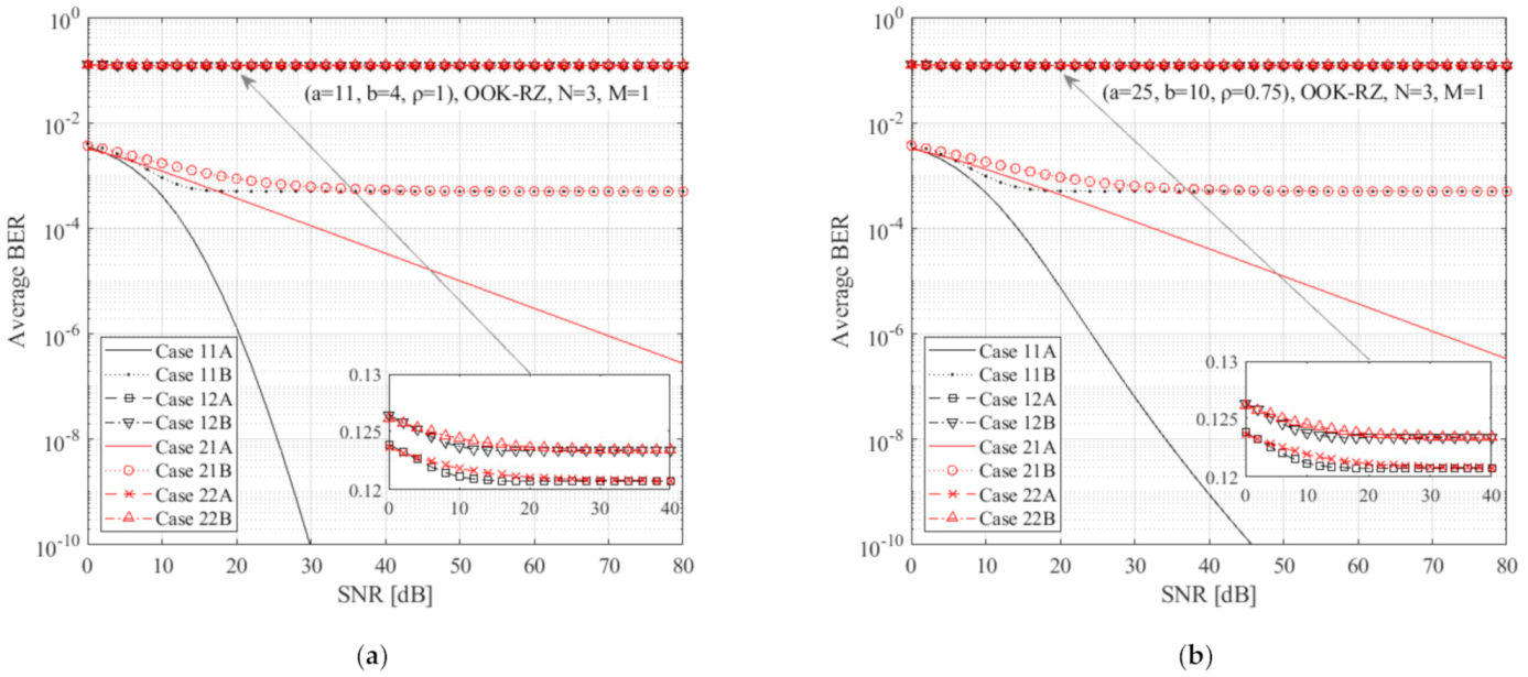
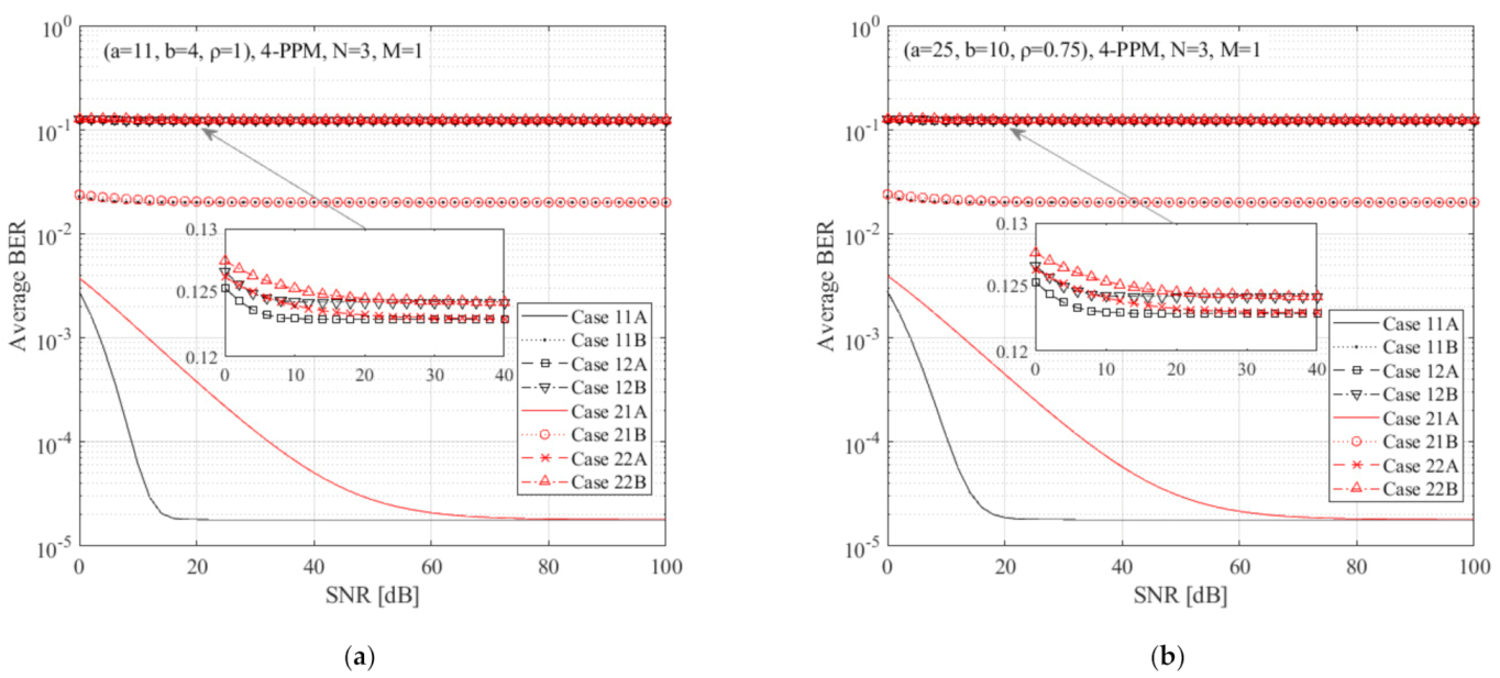
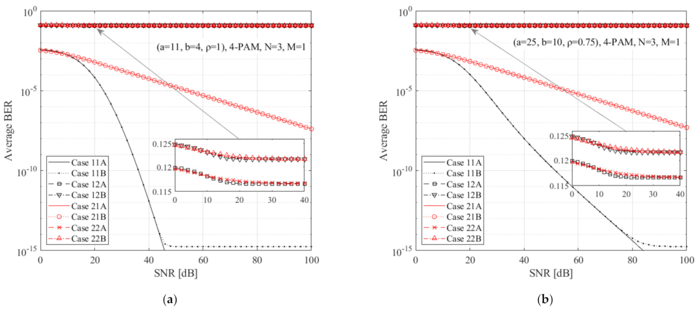
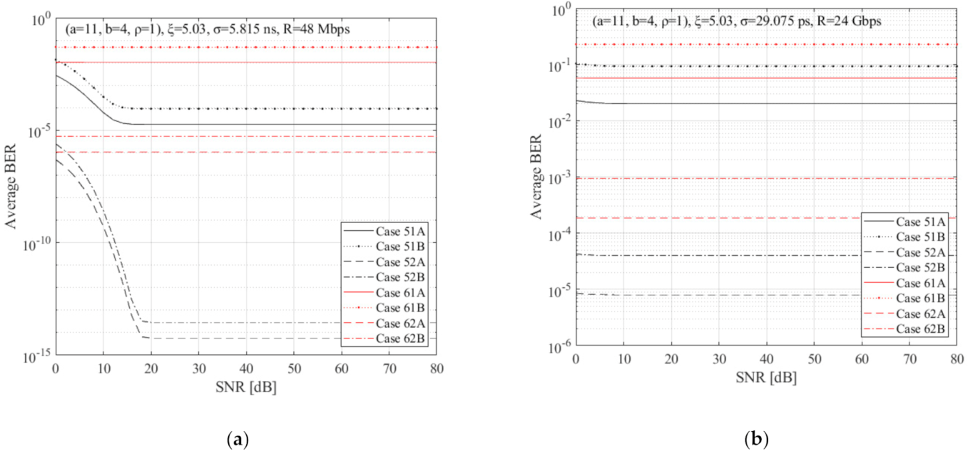
4. Numerical Results

Using the above-extracted mathematical expressions, (19), (20), and (22), the corresponding numerical results are presented in this section using common parameter values. Thus, variations of the parameters related to the system’s conditions, i.e., atmospheric turbulence, SJ, and TJ effects, with fixed receiver diversity (N = 3) and DF relaying (M = 1), are illustrated in Figure 2, Figure 3 and Figure 4 for particular parameters values of the modulation scheme, i.e., OOK-RZ, 4-PPM, and 4-PAM, respectively. Specifically, binary parameter combinations were studied in all three figures, including: ξ = 5.03 or 0.59, i.e., for weak or strong SJ effect, respectively, and whether α = 1 × 10⁻⁸ or 2 × 10⁻⁶ s, with β = 4 leading to σ = 5.815 × 10⁻⁹ or 1.163 × 10⁻⁶ s for bit rate R = 48 Mbps, or α = 5 × 10⁻¹¹ or 1 × 10⁻⁸ s (cases with σ = 1.163 × 10⁻⁶ s seem to be more typical of real systems for all studied modulation schemes, according to Table I of [18], however this benchmark is too large for Gbps rates, which are treated with much smaller σ values. For comparison, both bit rates were studied along with an intermediate value of σ = 5.815 × 10⁻⁹ s.), with β = 4 leading to σ = 29.075 × 10⁻¹² or 5.815 × 10⁻⁹ s for 24 Gbps, i.e., for weak or strong TJ effect, respectively [18], along with Málaga distribution parameter sets (a, b, ρ) = (11, 4, 1) (ρ = 1 corresponds to the GG sub-case.) or (25, 10, 0.75) for weak or strong turbulence conditions, respectively (corresponding to the atmosphere’s index of refraction structure parameters, C n 2 = 7.2 × 10⁻¹⁵ m−2/3 or 1.2 × 10⁻¹⁴ m−2/3 and Rytov variance, σ R 2 = 0.32 or 0.52, respectively, according to [13].). In all cases, Ω = 0.5 and b0 = 0.25, so that Ω + 2b0 = 1, implying that the average FSO link’s optical power is normalized. The rest factors for any individual link, minutely described in [13], include a propagation distance of 1 km and operating wavelength of λ = 785 nm.
Accordingly, variations of the operating system’s parameters, i.e., modulation scheme format, diversity, and DF relays, are illustrated in Figure 5, Figure 6 and Figure 7 for particular conditions, i.e., (a, b, ρ) = (11,4,1), ξ = 5.03, and either σ = 29.075 × 10⁻¹² s for R = 48 Mbps or σ = 5.815 × 10⁻⁹ s for 24 Gbps with α = 5 × 10⁻¹¹ or 1 × 10⁻⁸ s, respectively, and β = 4. Similarly, binary case combinations of diversity, N = 3 or 9, DF relaying, M = 1 or 5, and formats per modulation scheme family, i.e., OOK-RZ or NRZ, 4 or 16-PPM and 4 or 16-PAM, are shown in all three figures, along with selected bit rates.

5. Discussion

Comparing Figure 2, Figure 3 and Figure 4, the slopes of left panel are reasonably steeper than the respective right ones, as the former curves correspond to weaker turbulence than the latter ones. Additionally, the red curves, i.e., stronger SJ effect, have a smoother slope than the black ones, meaning that when link misalignments get significant, more SNR is required in order to achieve the same ABER level. What is more, faster links face stronger TJ effects than slower ones and when TJ is quite intense, the inevitably generated ABER thresholds get higher, particularly delimiting the performance of high-data-rate links. Finally, among the three studied modulation schemes, the OOK-RZ format presents moderate slopes and mediocre influence on TJ; the 4-PPM format has steeper slopes, but is heavily affected by the TJ effect; while the 4-PAM format is only slightly affected by TJ, but it presents smoother slopes.
Next, comparing Figure 4 and Figure 5, it can be seen that faster transmission links induce increased ABER thresholds in any case, with some of them tending to a completely flat performance. In addition, the individual link’s performance is significantly improved when the receiver’s diversity is higher. Furthermore, OOK-NRZ curves seem to be inferior to the corresponding OOK-RZ curves; however, both share the same ABER thresholds for any given TJ and bit rate values. For its part, the 16-PPM scheme curves are also inferior to the respective 4-PPM ones, but the expected steeper slope of the 16-PPM cases, allowing small BER to be achieved with less SNR requirements, is abolished, due to the large ABER thresholds. On the contrary, the 16-PAM scheme deepens the ABER performance with the respective 4-PAM. However, the improved curves are shifted to larger SNR values. Last but not least, expanding the total link’s length from one to five identical hops, all curves are slightly shifted to worse ABER performance; however, this degradation is inferior to the aggravated performance of a single hop link of the same total link length, as referred to in [24].

6. Conclusions

This work has dealt with the composite estimation of ABER performance of FSO links, subjected to atmospheric turbulence, SJ, and TJ effects, also taking N-OC diversity and M-DF multi-hop techniques into account, for three modulation scheme families, i.e., OOK-RZ/NRZ, L-PPM, or L-PAM. The study included the Málaga distribution model, for the atmospheric turbulence effect, the non-zero boresight SJ model, and the GGD model for the TJ effect. New, closed-form mathematical expressions for any studied case and practical numerical results for typical parameter values were also generated. Taking into account the above-derived expressions, the design and implementation of modern FSO links can be easier and more accurate. The influence of each effect have been described and the choice of the appropriate diversity scheme, along with the corresponding regenerator use, can be selected depending on the special characteristics of each specific area where the FSO link is installed.
The obtained outcomes show that the joint effects due to the weather conditions or/and receiver’s misalignment or/and desynchronization can be counterbalanced, allowing either further length expansion or bit rate incremental increase of the existing link. These features are feasible by increasing either the number of the receiver’s apertures and/or the number of DF relays implemented between the original transmitter and the final receiver or the order of PPM/PAM scheme, depending on the desired results in terms of ABER thresholds or SNR benchmarks, beyond which no further ABER performance is achievable.
The selection of the modulation format is crucial for the link’s performance and for either the curve’s slope, regulated by joint turbulence and SJ effect, or threshold, regulated by TJ effect and bit rate—steeper slopes allow a given ABER performance to be achieved at lower SNR values than in smoother slope cases, while deeper thresholds allow better ABER performance at the same SNR value than in shallower flat cases.
Finally, it should be mentioned that although this research concerned terrestrial links, the results obtained can also be implemented—with minor alterations—in underwater links, since the studied effects, among others, also exist in underwater optical wireless channels.

Author Contributions

Conceptualization, P.J.G., H.E.N., A.D.T. and E.R.; methodology, P.J.G., H.E.N., A.D.T., V.C. and E.R.; software, P.J.G. and A.D.T.; validation, P.J.G. and H.E.N.; formal analysis, P.J.G. and V.C.; investigation, P.J.G., H.E.N., A.D.T., V.C. and E.R.; resources, P.J.G. and H.E.N.; writing—original draft preparation, P.J.G.; writing—review and editing, H.E.N., A.D.T., V.C. and E.R.; visualization, A.D.T.; supervision, H.E.N.; funding acquisition, H.E.N. All authors have read and agreed to the published version of the manuscript.

Funding

This research received no external funding.

Institutional Review Board Statement

Not applicable.

Informed Consent Statement

Not applicable.

Data Availability Statement

Not applicable.

Conflicts of Interest

The authors declare no conflict of interest.

References

  1. Kedar, D.; Arnon, S. Urban optical wireless communication networks: The main challenges and possible solutions. IEEE Commun. Mag. 2004, 42, S2–S7. [Google Scholar] [CrossRef]
  2. Arnon, S. Optical Wireless Communications; Marcel Dekker Inc.: New York, NY, USA, 2003. [Google Scholar]
  3. Henniger, H.; Ludwig, A.; Horwath, J. Performance bounds of DPSK and OOK for low elevation optical LEO downlinks. Radioengineering 2010, 19, 589–595. [Google Scholar]
  4. Popoola, W.; Ghassemlooy, Z.; Lee, C.; Boucouvalas, A. Scintillation effect on intensity modulated laser communication systems—A laboratory demonstration. Opt. Laser Technol. 2010, 42, 682–692. [Google Scholar] [CrossRef]
  5. Andrews, L.C.; Phillips, R.L.; Young, C.Y. Laser Beam Scintillation with Applications; SPIE: Bellingham, WA, USA, 2001. [Google Scholar] [CrossRef] [Green Version]
  6. Andrews, L.C.; Al-Habash, M.A.; Hopen, C.Y.; Phillips, R.L. Theory of optical scintillation: Gaussian-beam wave model. Waves Random Media 2001, 11, 271–291. [Google Scholar] [CrossRef]
  7. Mahdieh, M.H.; Pournoury, M. Atmospheric turbulence and numerical evaluation of bit error rate (BER) in free-space communication. Opt. Laser Technol. 2010, 42, 55–60. [Google Scholar] [CrossRef]
  8. Tsiftsis, T.A.; Sandalidis, H.G.; Karagiannidis, G.K.; Uysal, M. Optical wireless links with spatial diversity over strong atmospheric turbulence channels. IEEE Trans. Wirel. Commun. 2009, 8, 951–957. [Google Scholar] [CrossRef] [Green Version]
  9. Moradi, H.; Falahpour, M.; Reafi, H.H.; LoPresti, P.G.; Atiquzzaman, M. Availability Modeling of FSO/RF Mesh Networks through Turbulence-Induced Fading Channels. In Proceedings of the 2010 INFOCOM IEEE Conference on Computer Communications Workshops, San Diego, CA, USA, 15–19 March 2010. [Google Scholar]
  10. Zhang, Y.; Si, C.; Wang, Y.; Wang, J.; Jia, J. Capacity for non-Kolmogorov turbulent optical links with beam wander and pointing errors. Opt. Laser Technol. 2011, 43, 1338–1342. [Google Scholar] [CrossRef]
  11. Upadhya, A.; Dwivedi, V.K.; Karagiannidis, G.K. On the Effect of Interference and Misalignment Error in Mixed RF/FSO Systems Over Generalized Fading Channels. IEEE Trans. Commun. 2020, 68, 3681–3695. [Google Scholar] [CrossRef]
  12. Jurado-Navas, A.; Maria, J.; Francisco, J.; Puerta-Notario, A. A Unifying Statistical Model for Atmospheric Optical Scintillation. Numer. Simul. Phys. Eng. Process. 2011, 1–4. [Google Scholar] [CrossRef] [Green Version]
  13. Jurado-Navas, A.; Balsells, J.M.G.; Paris, J.F.; Vázquez, M.D.C.; Notario, A.P. Impact of pointing errors on the performance of generalized atmospheric optical channels. Opt. Express 2012, 20, 12550–12562. [Google Scholar] [CrossRef]
  14. Sandalidis, H. Optimization Models for Misalignment Fading Mitigation in Optical Wireless Links. IEEE Commun. Lett. 2008, 12, 395–397. [Google Scholar] [CrossRef]
  15. Islam, K.M.N.; Majumder, S.P. Effect of timing jitter on the BER performance of a M-PPM FSO link over atmospheric turbulence channel. In Proceedings of the 8th International Conference on Electrical and Computer Engineering, Dhaka, Bangladesh, 20–22 December 2014; pp. 409–412. [Google Scholar] [CrossRef]
  16. Essiambre, R.-J.; Agrawal, G.P. Timing jitter analysis for optical communication systems using ultrashort solitons and dispersion-decreasing fibers. Opt. Commun. 1996, 131, 274–278. [Google Scholar] [CrossRef]
  17. Li, Y.; Geng, T.; Ma, S.; Gao, S. Timing jitter’s influence on the symbol error rate performance of the L -ary pulse position modulation free-space optical link in atmospheric turbulent channels with pointing errors. Opt. Eng. 2017, 56, 36116. [Google Scholar] [CrossRef]
  18. Lazer, N.; Teen, Y.P.A. Free Space Optical Communication and Laser Beam Propagation through Turbulent Atmosphere: A Brief Survey. In Proceedings of the 2019 International Conference on Recent Advances in Energy-efficient Computing and Communication (ICRAECC), Nagercoil, India, 7–8 March 2019. [Google Scholar] [CrossRef]
  19. Wang, Y.; Zhang, Y.; Dou, Z.; Tian, D. The Influence of Timing Error on the Performance of Optical Pulse PPM System in Atmospheric Turbulent Channels. In Proceedings of the 2010 Symposium on Photonics and Optoelectronics, Chengdu, China, 19–21 June 2010; pp. 1–4. [Google Scholar] [CrossRef]
  20. Hamming, R.W. Error Detecting and Error Correcting Codes. Bell Syst. Tech. J. 1950, 29, 147–160. [Google Scholar] [CrossRef]
  21. Sheng, M.; Jiang, P.; Hu, Q.; Su, Q.; Xie, X.-X. End-to-end average BER analysis for multihop free-space optical communications with pointing errors. J. Opt. 2013, 15. [Google Scholar] [CrossRef]
  22. Ai, Y.; Mathur, A.; Cheffena, M.; Bhatnagar, M.R.; Lei, H. Physical Layer Security of Hybrid Satellite-FSO Cooperative Systems. IEEE Photonics J. 2019, 11, 1–14. [Google Scholar] [CrossRef]
  23. Xu, F.; Khalighi, A.; Caussé, P.; Bourennane, S. Channel coding and time-diversity for optical wireless links. Opt. Express 2009, 17, 872–887. [Google Scholar] [CrossRef] [PubMed]
  24. Gripeos, P.; Nistazakis, H.; Roumelas, G.; Christofilakis, V.; Tsigopoulos, A.; Tombras, G. DF Relayed OOK and PAM FSO Links with Turbulence and Time Jitter. In Proceedings of the 2020 International Conference on Broadband Communications for Next Generation Networks and Multimedia Applications (CoBCom), Graz, Austria, 7–9 July 2020; pp. 1–7. [Google Scholar]
  25. Brennan, D. Linear Diversity Combining Techniques. Proc. IRE 1959, 47, 1075–1102. [Google Scholar] [CrossRef]
  26. Simon, M.K.; Alouini, M.-S. Digital Communication Over Fading Channels; Wiley-Interscience: New York, NY, USA, 2000. [Google Scholar]
  27. Nistazakis, H.E. A time-diversity scheme for wireless optical links over exponentially modeled turbulence channels. Optik 2013, 124, 1386–1391. [Google Scholar] [CrossRef]
  28. Navidpour, S.M.; Uysal, M.; Kavehrad, M. BER Performance of Free-Space Optical Transmission with Spatial Diversity. IEEE Trans. Wirel. Commun. 2007, 6, 2813–2819. [Google Scholar] [CrossRef] [Green Version]
  29. Wang, Z.; Zhong, W.-D.; Fu, S.; Lin, C. Performance comparison of different modulation formats over free-space optical (FSO) turbulence links with space diversity reception technique. IEEE Photonics J. 2009, 1, 277–285. [Google Scholar] [CrossRef]
  30. Shin, E.J.; Chan, V.W.S. Optical communication over the turbulent atmospheric channel using spatial diversity. In Proceedings of the Global Telecommunications Conference, GLOBECOM ’02, Taipei, Taiwan, 17–21 November 2002; Volume 3. [Google Scholar] [CrossRef]
  31. Mishra, N.; Kumar, D.S. Outage analysis of relay assisted FSO systems over K-distribution turbulence channel. In Proceedings of the 2016 International Conference on Electrical, Electronics, and Optimization Techniques (ICEEOT), Chennai, India, 3–5 March 2016; pp. 2965–2967. [Google Scholar]
  32. Garrido-Balsells, J.M.; Lopez-Martinez, F.J.; Castillo-Vázquez, M.; Jurado-Navas, A.; Puerta-Notario, A. Performance analysis of FSO communications under LOS blockage. Opt. Express 2017, 25, 25278–25294. [Google Scholar] [CrossRef] [PubMed] [Green Version]
  33. Modified Bessel Function of the Second Kind: Representations through More General Functions (Formula 03.04.26.0009). Available online: https://functions.wolfram.com/03.04.26.0009.01 (accessed on 29 July 2021).
  34. Adamchik, V.S.; Marichev, O.I. The algorithm for calculating integrals of hypergeometric type functions and its realization in REDUCE system. In Proceedings of the International Symposium on Symbolic and Algebraic Computation—ISSAC ’90, Tokyo, Japan, 20–24 August 1990. [Google Scholar]
  35. Al-Habash, M.A. Mathematical model for the irradiance probability density function of a laser beam propagating through turbulent media. Opt. Eng. 2001, 40, 1554. [Google Scholar] [CrossRef]
  36. Jakeman, E. On the statistics of K-distributed noise. J. Phys. A Math. Gen. 1980, 13, 31–48. [Google Scholar] [CrossRef]
  37. Ninos, M.; Nistazakis, H.; Tombras, G. On the BER performance of FSO links with multiple receivers and spatial jitter over gamma-gamma or exponential turbulence channels. Optik 2017, 138, 269–279. [Google Scholar] [CrossRef]
  38. Farid, A.A.; Hranilovic, S. Outage Capacity Optimization for Free-Space Optical Links With Pointing Errors. J. Light. Technol. 2007, 25, 1702–1710. [Google Scholar] [CrossRef] [Green Version]
  39. Sandalidis, H.G.; Tsiftsis, T.A.; Karagiannidis, G.K. Optical Wireless Communications With Heterodyne Detection Over Turbulence Channels With Pointing Errors. J. Light. Technol. 2009, 27, 4440–4445. [Google Scholar] [CrossRef]
  40. Gappmair, W. Novel results on pulse-position modulation performance for terrestrial free-space optical links impaired by turbulent atmosphere and pointing errors. IET Commun. 2012, 6, 1300–1305. [Google Scholar] [CrossRef]
  41. Varotsos, G.; Nistazakis, H.; Petkovic, M.; Djordjevic, G.; Tombras, G. SIMO optical wireless links with nonzero boresight pointing errors over M modeled turbulence channels. Opt. Commun. 2017, 403, 391–400. [Google Scholar] [CrossRef]
  42. Nadarajah, S. A generalized normal distribution. J. Appl. Stat. 2005, 32, 685–694. [Google Scholar] [CrossRef]
  43. Hranilovic, S. Wireless Optical Communication Systems; Springer: New York, NY, USA, 2005; pp. 51–64. [Google Scholar] [CrossRef]
  44. Proakis, J.G.; Salehi, M. Communication Systems Engineering, 2nd ed.; Prentice Hall: Hoboken, NJ, USA, 2002. [Google Scholar]
  45. Loskot, P.; Beaulieu, N.C. Prony and Polynomial Approximations for Evaluation of the Average Probability of Error Over Slow-Fading Channels. IEEE Trans. Veh. Technol. 2008, 58, 1269–1280. [Google Scholar] [CrossRef]
  46. Meijer G-Function: Integration (Formula 07.34.21.0013). Available online: https://functions.wolfram.com/HypergeometricFunctions/MeijerG/21/02/03/01/0002/ (accessed on 14 February 2021).
  47. Exponential Function: Representations through More General Functions (Formula 01.03.26.0004). Available online: https://functions.wolfram.com/01.03.26.0004.01 (accessed on 29 July 2021).
  48. Roumelas, G.; Nistazakis, H.; Gappmair, W.; Gripeos, P.; Christofilakis, V. Time jitter influence on the performance of gamma–gamma turbulence FSO links with various modulation schemes. J. Mod. Opt. 2020, 67, 721–729. [Google Scholar] [CrossRef]
  49. Morgado, E.; Mora-Jimenez, I.; Vinagre, J.J.; Ramos-López, J.; Caamano, A.J. End-to-End Average BER in Multihop Wireless Networks over Fading Channels. IEEE Trans. Wirel. Commun. 2010, 9, 2478–2487. [Google Scholar] [CrossRef] [Green Version]
Figure 1. Schematic diagram of the system’s configuration with M DF relayed multi-hop and N OC receiver diversity for each individual link.
Photonics 08 00318 g001
Figure 2. ABER versus expected SNR for the OOK-RZ scheme, N = 3, M = 1, with various bit rates and spatial and time jitter conditions of (a) (a = 11, b = 4, ρ = 1) and (b) (a = 25, b = 10, ρ = 0.75). The studied curve cases are codified as follows: Case 11A: ξ = 5.03, σ = 5.815 × 10⁻⁹ s, 48 Mbps; Case 11B: ξ = 5.03, σ = 29.075 × 10⁻¹² s, 24 Gbps; Case 12A: ξ = 5.03, σ = 1.163 × 10⁻⁶ s, 48 Mbps; Case 12B: ξ = 5.03, σ = 5.815 × 10⁻⁹ s, 24 Gbps; Case 21A: ξ = 0.59, σ = 5.815 × 10⁻⁹ s, 48 Mbps; Case 21B: ξ = 0.59, σ = 29.075 × 10⁻¹² s, 24 Gbps; Case 22A: ξ = 0.59, σ = 1.163 × 10⁻⁶ s, 48 Mbps; and Case 22B: ξ = 0.59, σ = 5.815 × 10⁻⁹ s, 24 Gbps.
Photonics 08 00318 g002
Figure 3. ABER versus expected SNR for the 4-PPM scheme, N = 3, M = 1, with various bit rates and spatial and time jitter conditions of (a) (a = 11, b = 4, ρ = 1) and (b) (a = 25, b = 10, ρ = 0.75). The studied curve cases are codified as in Figure 2.
Photonics 08 00318 g003
Figure 4. ABER versus expected SNR for 4-PAM scheme, N = 3, M = 1, with various bitrates and spatial and time jitter conditions of (a) (a = 11, b = 4, ρ = 1) and (b) (a = 25, b = 10, ρ = 0.75). The studied curve cases are codified as in Figure 2.
Photonics 08 00318 g004
Figure 5. ABER versus expected SNR for (a = 11, b = 4, ρ = 1), ξ = 5.03, OOK-RZ/NRZ schemes, and various diversity and DF multi-hop parameters, with (a) R = 48 Mbps, σ = 5.815 × 10⁻⁹ s (α = 10−8 s, β = 4) and (b) R = 24 Gbps, σ = 29.075 × 10⁻¹² s (α = 5 × 10⁻¹¹ s, β = 4). The studied curve cases are codified as follows: Case 31A: OOK-RZ,N = 3, M = 1; Case 31B: OOK-RZ, N = 3, M = 5; Case 32A: OOK-RZ, N = 9, M = 1; Case 32B: OOK-RZ, N = 9, M = 5; Case 41A: OOK-NRZ, N = 3, M = 1; Case 41B: OOK-NRZ, N = 3, M = 5; Case 42A: OOK-NRZ, N = 9, M = 1; Case 42B: OOK-NRZ, N = 9, M = 5.
Photonics 08 00318 g005
Figure 6. ABER versus expected SNR for (a = 11, b = 4, ρ = 1), ξ = 5.03, L-PPM schemes, and various diversity and DF multi-hop parameters, with (a) R = 48 Mbps, σ = 5.815 × 10⁻⁹ s (α = 10−8 s, β = 4) and (b) R = 24 Gbps, σ = 29.075 × 10⁻¹² s (α = 5 × 10⁻¹¹ s, β = 4). The studied curve cases are codified as follows: Case 51A: 4-PPM, N = 3, M = 1; Case 51B: 4-PPM, N = 3, M = 5; Case 52A: 4-PPM, N = 9, M = 1; Case 52B: 4-PPM, N = 9, M = 5; Case 61A: 16-PPM, N = 3, M = 1; Case 61B: 16-PPM, N = 3, M = 5; Case 62A: 16-PPM, N = 9, M = 1; Case 62B: 16-PPM, N = 9, M = 5.
Photonics 08 00318 g006
Figure 7. ABER versus expected SNR for (a = 11, b = 4, ρ = 1), ξ = 5.03, L-PAM schemes, and various diversity and DF multi-hop parameters, with (a) R = 48 Mbps, σ = 5.815 × 10⁻⁹ s (α = 10−8 s, β = 4), and (b) R = 24 Gbps, σ = 29.075 × 10⁻¹² s (α = 5 × 10⁻¹¹ s, β = 4). The studied curve cases are codified as follows: Case 71A: 4-PAM, N = 3, M = 1; Case 71B: 4-PAM, N = 3, M = 5; Case 72A: 4-PAM, N = 9, M = 1; Case 72B: 4-PAM, N = 9, M = 5; Case 81A: 16-PAM, N = 3, M = 1; Case 81B: 16-PAM, N = 3, M = 5; Case 82A: 16-PAM, N = 9, M = 1; Case 82B: 16-PAM, N = 9, M = 5.
Photonics 08 00318 g007
Publisher’s Note: MDPI stays neutral with regard to jurisdictional claims in published maps and institutional affiliations.

