Communication

Multi-View Optical Image Fusion and Reconstruction for Defogging without a Prior In-Plane

1
State Key Laboratory of Optoelectronic Materials and Technologies, School of Physics, Sun Yat-Sen University, Guangzhou 510275, China
2
Southern Marine Science and Engineering Guangdong Laboratory, Zhuhai 519000, China
3
Shanghai Institute of Optics and Fine Mechanics, Chinese Academy of Sciences, Shanghai 201800, China
4
CMA Shanghai Material Management Office, Shanghai 200050, China
*
Author to whom correspondence should be addressed.
These authors contributed equally to this work.
Photonics 2021, 8(10), 454; https://doi.org/10.3390/photonics8100454
Submission received: 31 August 2021 / Revised: 9 October 2021 / Accepted: 12 October 2021 / Published: 18 October 2021
(This article belongs to the Special Issue Smart Pixels and Imaging)

Abstract

:
Image fusion and reconstruction from muldti-images taken by distributed or mobile cameras need accurate calibration to avoid image mismatching. This calibration process becomes difficult in fog when no clear nearby reference is available. In this work, the fusion of multi-view images taken in fog by two cameras fixed on a moving platform is realized. The positions and aiming directions of the cameras are determined by taking a close visible object as a reference. One camera with a large field of view (FOV) is applied to acquire images of a short-distance object which is still visible in fog. This reference is then adopted to the calibration of the camera system to determine the positions and pointing directions at each viewpoint. The extrinsic parameter matrices are obtained with these data, which are applied for the image fusion of distant images captured by another camera beyond visibility. The experimental verification was carried out in a fog chamber and the technique is shown to be valid for imaging reconstruction in fog without a prior in-plane. The synthetic image, accumulated and averaged by ten-view images, is shown to perform potential applicability for fog removal. The enhanced structure similarity is discussed and compared in detail with conventional single-view defogging techniques.

1. Introduction

Optical imaging beyond visibility is particularly important for a multitude of applications, such as surveillance, remote sensing, and navigation in fog. However, light emanating from an object is scattered and diverted by molecules, aerosols, and turbulence. Based on the atmospheric scattering model, scattering processes increase the random noise and reduce the object signal strength [1,2]. These phenomena, which cause a lower signal-to-noise ratio (SNR), give rise to the spatial blurring of the image when the object is beyond the visible range.
Multiple techniques of optical image reconstruction have been extensively applied in difficult weather conditions for quite some time, such as adaptive optics [3,4,5,6], which has achieved a lot in recent years. However, optical imaging in dense fog cannot be substantially enhanced by simple waveform correction. Therefore, multiple fog removal algorithms [7,8,9,10,11,12,13,14,15], which work by improving weak transmission images, have been proposed for situations of dense fog. For various image acquisition methods, the frame accumulation technique has shown to be valid for image denoising by suppressing noise variance, hence improving the grayscale resolution and SNR [16,17,18,19]. The frame accumulation can be carried out on a stationary stage. However, for many application purposes, the camera and object are moving with each other. It is then necessary to record and process the images on a moving platform. Due to image mismatching [20,21,22], frame accumulation cannot be simply adapted to a moving camera. Therefore, it is imperative to carry out the image accumulation on a moving camera platform. The more challenging issue is to aim and calibrate the camera location and pointing direction in fog, where no prior reference is visible for the aiming object.
In this work, a novel technique for the fusion and accumulation of multi-view blurred images of invisible targets in dense fog is proposed, where the close object within visibility range is visible, while the distant target beyond visibility is invisible. In this situation, pixels acting as smart pixels [23,24] carry information for the locations and pointing directions for distributed recording cameras, which can be calibrated with the assistance of multi-view visible images of the close object. By using such position and pointing direction parameters, the extrinsic parameter matrices are calculated and applied to the image fusion of the invisible target out of the visible range. This experiment shows that multi-view imaging utilizes non-coplanar objects as prior information to achieve image fusion for distant invisible objects. Experimental results show that such a scheme can be adapted to a camera on a moving platform to improve the grayscale resolution and SNR of the image. Enhanced details and edge restoration are realized simultaneously.

2. Theory

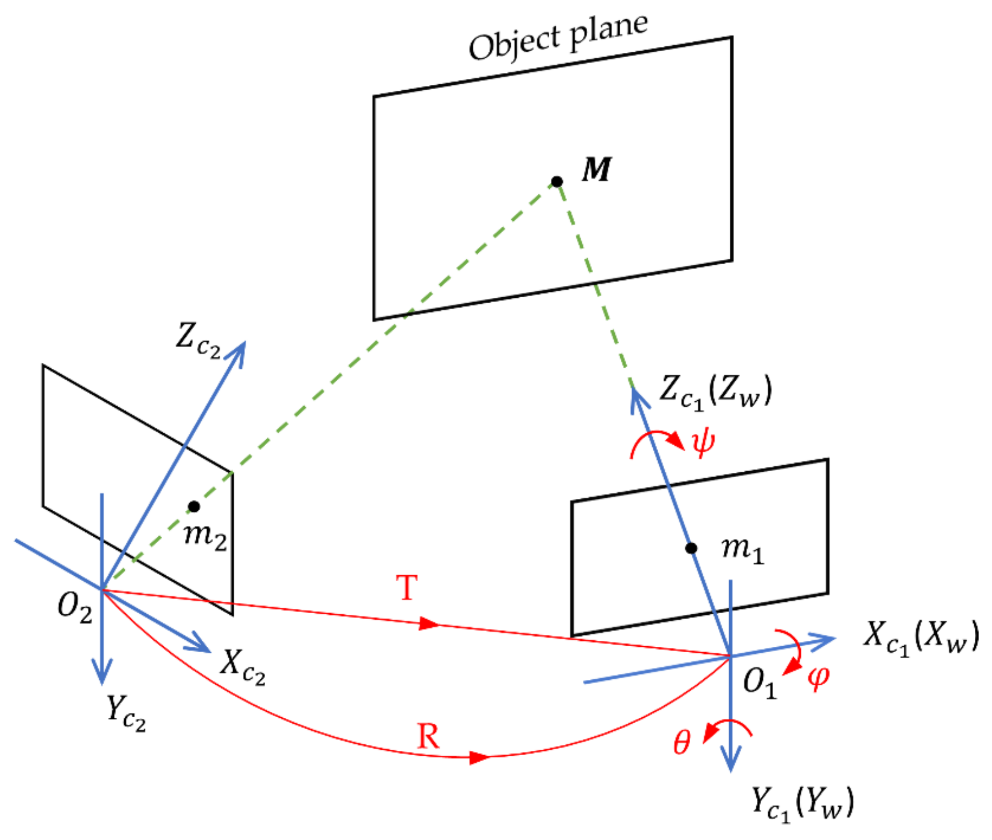
2.1. Projective Geometry

The projection matrix, known as the homography matrix of two images from different views with the position and direction information of the camera, is described in reference [25] and is applied in this work for system calibration. In Figure 1, cameras located at two positions, O 1 and O 2 , observe the same scene, consisting of a set of coplanar feature points, and acquire the desired image I 1 and the current image I 2 , respectively. In this scene, M X w , Y w , Z w T is one point of the object plane in the world coordinate, which is transformed to the two camera coordinates denoted as M 1 X c 1 , Y c 1 , Z c 1 T and M 2 X c 2 , Y c 2 , Z c 2 T , respectively. Then, m 1 u 1 , v 1 , 1 T and m 2 u 2 , v 2 , 1 T are the projective points of M on the corresponding images. T represents the translation from O 2 to O 1 , while R represents the rotation from O 2 to O 1 . The first camera is chosen to be the reference camera, so that O 1 is the origin of the world coordinate.
According to the principle of imaging in cameras, the relationship between the pixel coordinate and camera coordinate for camera C 1 is:
Z c 1 m 1 = K M 1
Similarly, the same expression for camera C 2 is adaptable as:
Z c 2 m 2 = K M 2
where Z c 1   and Z c 2 denote the distance from the object plane to the corresponding camera plane, and K denotes the camera intrinsic matrix, only related to the camera parameters that can be calibrated.
According to the theory of Rigid-Body Transformation, the relationship between camera coordinates M 1 and M 2 is formulated as:
M 1 = R M 2 + T
where T = T x , T y , T z T is a translation vector and R is a 3 × 3 rotation matrix related to the camera direction information, including pitch angle φ , yaw angle θ , and roll angle ψ . Therefore, T and R are irrelevant to the object distance Z c and only depend on the position and direction parameters of the camera, respectively. The specified relationship between R and the angles φ , θ , ψ is:
R x = 1 0 0   0 c o s φ s i n φ   0 s i n φ c o s φ , R y = c o s θ 0 s i n θ   0 1 0   s i n θ 0 c o s θ , R z = c o s ψ s i n ψ 0   s i n ψ c o s ψ 0   0 0 1
A unit vector n = 0 , 0 , 1 is introduced to Equation (3), considering that the plane of the reference camera is parallel to the focal plane. In the reference camera coordinate M 1 , all feature points are in the focal plane of the target, satisfying:
n M 1 = Z c 1
Therefore, Equation (3) can be transformed to a new formula, as follows:
I T n Z c 1 M 1 = R M 2
where I denotes a 3 × 3 unit matrix.
Considering the above equations from Equation (1) to Equation (6), the two images taken by a moving camera in the pixel coordinate satisfy the following relationship:
m 1 = Z c 2 Z c 1 K I T n Z c 1 1 R K 1 m 2
From Equation (7), the accurate position and direction information T , R of a camera and the corresponding focal plane parameters n ,   Z c 1 are needed for image registration, following the model m 1 = Z c 2 Z c 1 H m 2 , where H is a homography matrix acting as a projective matrix, as follows:
H = K I T n Z c 1 1 R K 1
Only the objects at the depth of Z c 1 can be accurately matched and superimposed by Equation (8). This property can enhance the signal in the object plane while suppressing the off-plane noise.

2.2. Multiple Views Motion Estimation

Due to the errors of camera position and direction parameters, the inaccurate homography matrices will be calculated and finally give rise to reprojection errors on image fusion, as described in [26]. In this work, the position parameters are provided by the translation stage with 0.05 mm re-orientation precision. However, the direction parameters provided by the rotary stage, with 0.2-degree precision, will lead to great reprojection errors in image fusion. Therefore, a proposed method to calibrate the camera direction parameters is realized with the assistance of a close object in the visible range. From Equation (8), R can be decomposed from H , shown as:
R = I T n Z c 1 K 1 H K
In the case of the inability to distinguish the distant target out of visible range, we extract feature points on visible images of the close object to calibrate the position and direction parameters of the camera from different views. There is a strict requirement that the plane of the close object must be parallel to the plane of the distant target, which ensures that the two planes have the same normal vector. This condition can be met for long-range optical imaging, where the inclination in two different planes can be neglected. The overall process of experiments is shown in Figure 2.
For the situation of N views with camera center C 1 , , C N , let I i i = 1 , , N be the image from multiple views and H i be the corresponding homography matrix required to project I i on the plane of the reference image I 1 . Mathematically, the synthetic image with images accumulated from multiple views is given by [27]:
I 0 = 1 N i = 1 N H i I i
where I 0 is the synthetic image and H i I i is the projection of image I i onto the reference plane I 1 . Multiple images, from different views, carrying different signals, are finally fused into one image, which means that pixels on the same focal plane will be projected to the same location and enhance the SNR.

3. Experiment and Results

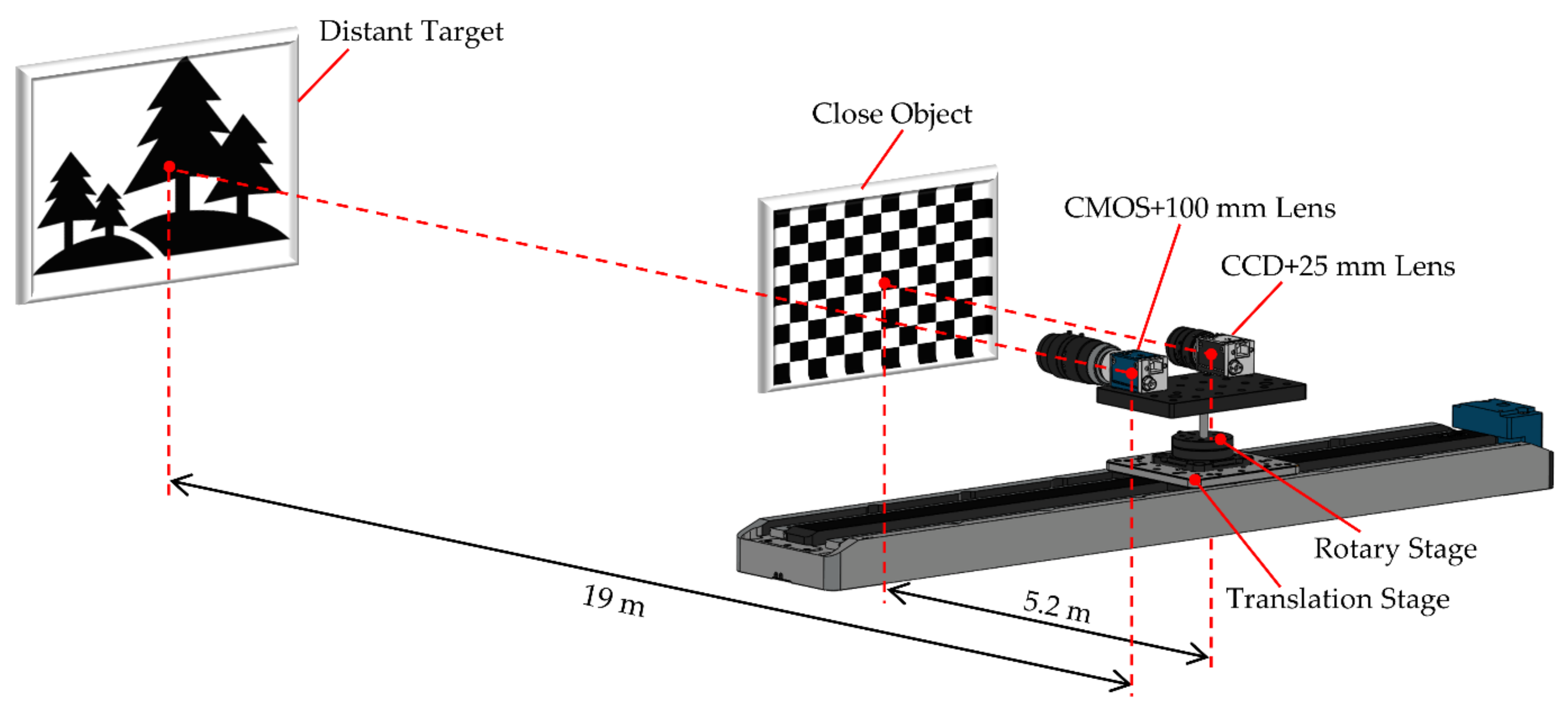
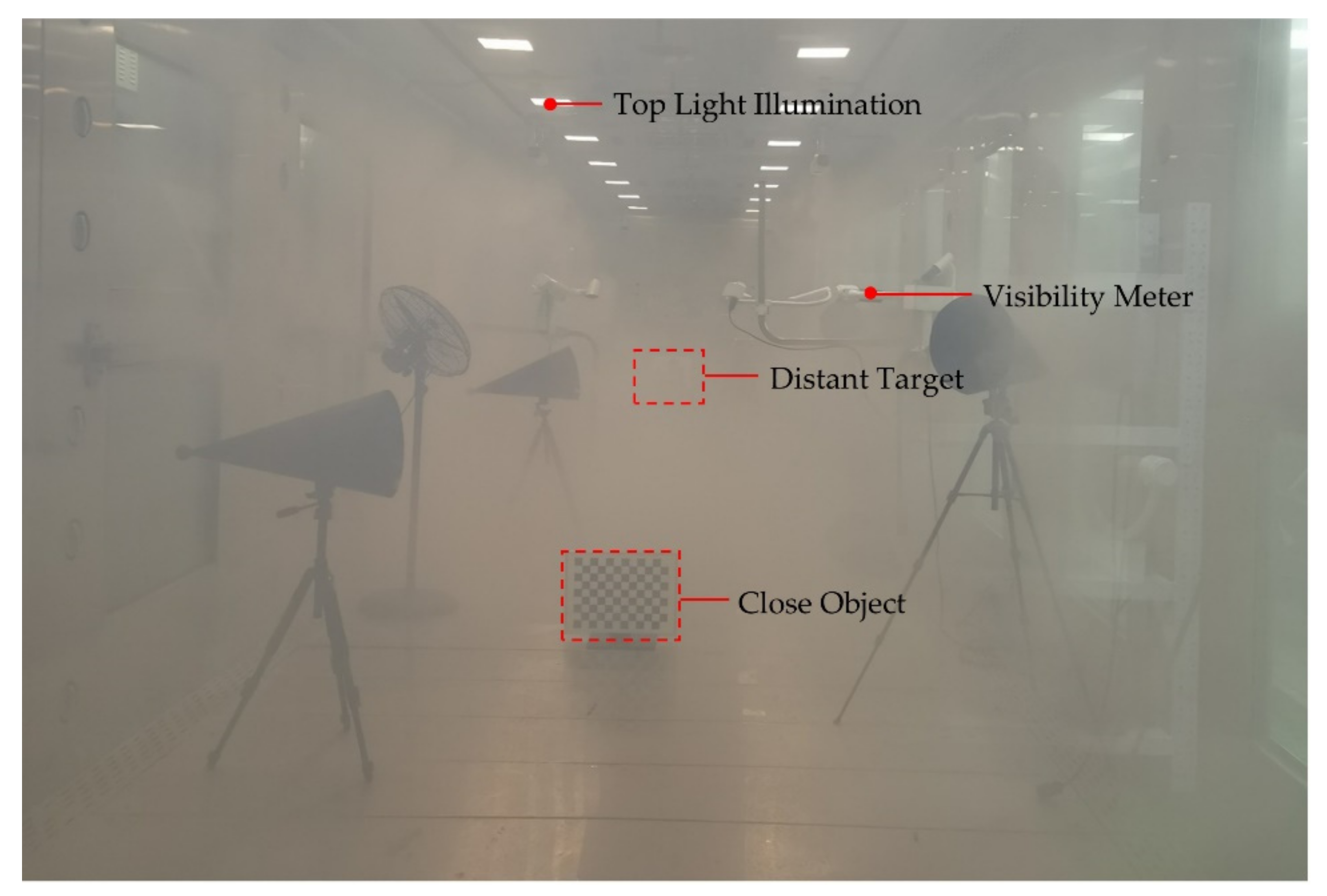
3.1. Experimental Setup

The experimental setup is shown in Figure 3. The translational motion was provided by a three-axis motorized translation stage (re-orientation precision, 0.05 mm; total range, 550 mm) which is controlled by a stepper motor controller (Bocic SC100). The one-dimensional rotary stage (RSM100-1W; precision, 0.2°; total range, 360°), installed on a translation stage, controls the overall rotation of the two cameras to realize the camera rotation on the multi-view platform.
Two cameras, as a camera system with fixed relative positions and directions on the rotary stage, are aimed at the close object and distant target, respectively, where a CCD (Basler acA1300-30gm; pixel size, 3.75 µm × 3.75 µm; resolution, 1200 × 960) with a 25 mm lens (Computar M2518-MPW2) shoots the close object while the CMOS (Flir BFS-PGE-51S5P-C; pixel size, 3.45 µm × 3.45 µm; resolution, 2048 × 2448) with a 100 mm lens (Zeiss Milvus 2/100 mm) shoots the distant target.
The experiment was carried out in a 20 m × 3 m × 3 m fog chamber capable of producing fog at different levels of visibility. A photograph of a thinly foggy environment in the fog chamber is shown in Figure 4. The lighting in the fog chamber is provided by fluorescent lamps (ZOGLAB) in the visible spectrum. The duration of fog filling is 12 min each time, with water mist particles generated by the instrument chamber.

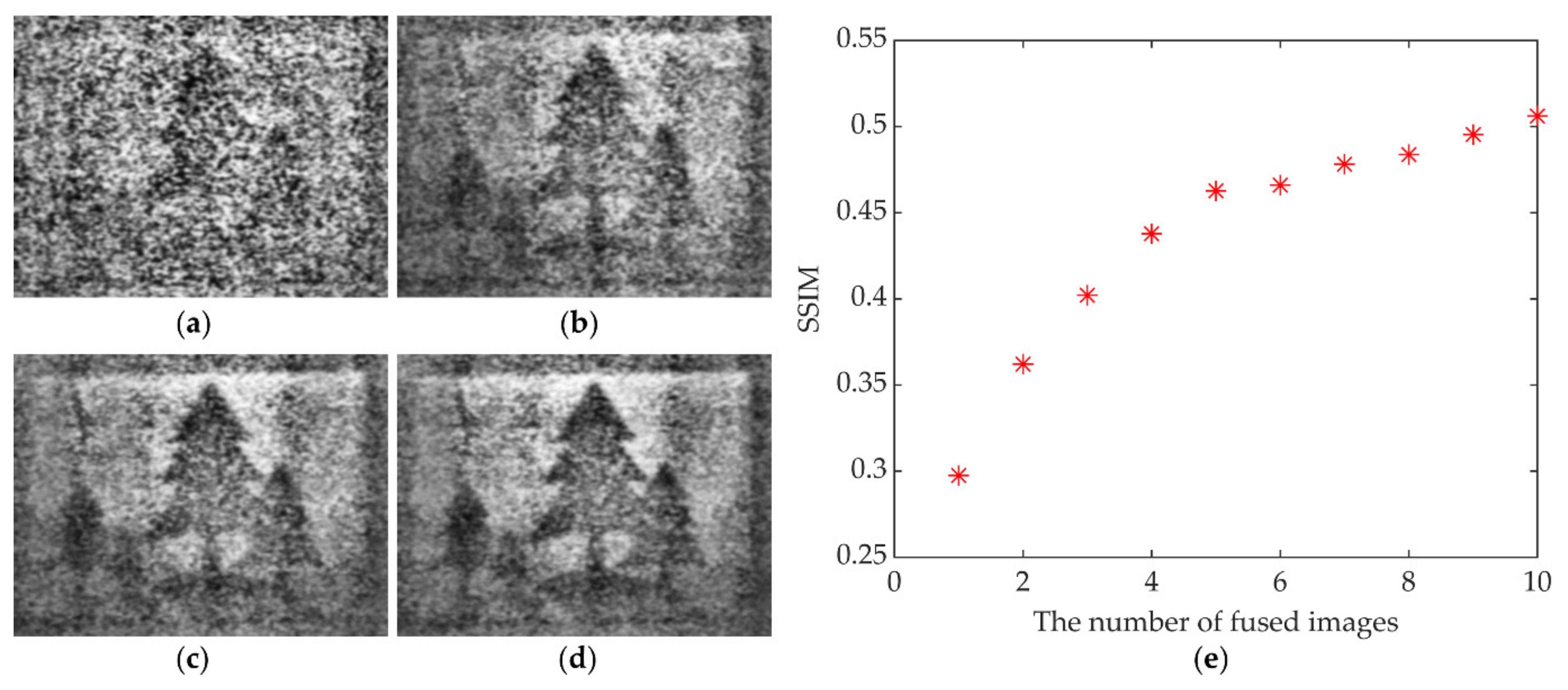
3.2. Image Acquisition and Multi-View Image Fusion

In this experiment, we first set the position information for 1-by-10 views of the camera system via a translation stage. The ten viewpoint position parameters T i i = 1 , 10 , relative to the first viewpoint, are listed in Table 1.
After the cameras arrived at each viewpoint successively, ten images of the close object in the visible range and ten images of the distant target beyond visibility from the 1-by-10 viewpoints in sequence were captured at 8 m visibility, as shown in Figure 5 and Figure 6.
From Figure 5 and Figure 6, the chessboard as the close object is clearly distinguishable, while the distant target beyond visibility is completely invisible. Figure 5a, captured in the first view, is assumed to be the reference image. We first match Figure 5b to Figure 5j with Figure 5a, respectively, by feature-point extraction on the chessboard plane, to obtain H i c l o s e i = 2 , 10 of the visible images. Then, the rotation matrices R i i = 2 , 10 of each viewpoint, relative to the reference viewpoint, can be calculated with Equation (9). The ten viewpoint direction parameters, with angles ( φ , θ , ψ ) relative to the first viewpoint, can be decomposed from R i i = 1 , 10 with Equation (4), as listed in Table 2.
Combined with the above position and direction parameters of the camera system, the new homography matrices H i d i s t a n t i = 2 , 10 for invisible-image fusion are calculated with Equation (8). This technique is shown to be capable of realizing image fusion and accumulation for fog removal, as presented in Figure 7.

3.3. Image Defogging

The synthetic images were first fused and accumulated separately by different numbers of images from the corresponding viewpoints. The defogging results obtained by utilizing a multi-scale Retinex (MSR) algorithm [12,14,28,29] are shown in Figure 7. The relationship between the image quality—evaluated by the structure similarity (SSIM) [30]—and the number of fused images is illustrated in Figure 7e.
From the above results, this experiment verifies the capability for fog removal by multi-view image fusion with Equation (7). Visually, with more viewpoint images fused, a better defogging effect can be realized. Compared with the single-image defogging result in Figure 7a, more detailed information and edges were preserved in Figure 7b–d, which means the synthetic image fused with multi-view images enhances image contrast as well as effectively filtering out noise. In Figure 7e, with the number of viewpoints increasing, the corresponding SSIM rises accordingly.
Quantitative evaluation of image quality is illustrated in Table 3. As can be seen, the SSIM of Figure 7d is 0.5061, which is approximately 60% improved compared with Figure 7a.
Furthermore, the peak signal-to-noise ratio (PSNR) and signal-to-noise ratio (SNR) of Figure 7d are both increased by about 0.9 dB. The above results show that a single camera on a moving platform, capturing multi-view images, can be used to perform fog removal with improved ability.

4. Discussion

It should be pointed out that the disparity of the multi-view viewpoints can be neglected for this experiment. For long-range imaging, the disparity hardly affects the depth of field with only a 525 mm baseline of multi-view imaging on the moving platform. Therefore, Equation (7) is suitable for objects at two different depths for image fusion.
It is worth noting that when extracting feature points on visible images of the near object, due to the interference of fog and non-uniform illumination, the feature points between two images are inevitably mismatched at a pixel level, which results in inaccurate direction parameters of the camera. Therefore, the optimization algorithm of feature-point matching should be studied in future work.

5. Conclusions

Due to the significant improvement of image accumulation for fog removal, a multi-view image fusion and accumulation technique is proposed in this work to address image mismatching on a moving camera. With the assistance of a close object to calibrate the direction and position parameters of the camera, an extrinsic parameter matrix can be calculated and applied to the image fusion of a distant invisible object. Experimental results demonstrate that single-image defogging misses much image information, while the synthetic image fused by multi-view images performs better detail and edge restoration simultaneously, which is approximately twice improved in SSIM. Hence, the proposed technique is shown to achieve multi-view optical image fusion and the restoration of a distant target in dense fog, overcoming the problem of image mismatching on a moving platform by using non-coplanar objects as prior information in an innovative way. The experimental demonstration indicates that this technique is particularly useful for bad weather atmosphere conditions.

Author Contributions

Y.H. conducted the camera calibration, matrix transformation, experimental investigation, and manuscript preparation; H.L. (Haishan Liu), Y.S., G.Z. carried out the measurement in the fog chamber; J.C., G.S., Z.L. supervised the project and participated in the manuscript preparation; J.Z. initiated and supervised the project and prepared the manuscript; H.L. (Haowen Liang) proposed, organized, and supervised the project and Y.L. organized, executed, and applied for funding for the project. All authors have read and agreed to the published version of the manuscript.

Funding

This research was funded by the National Natural Science Foundation of China (Nos. 61991452 and 12074444); Guangdong Major Project of Basic and Applied Basic Research (No. 2020B0301030009); Guangdong Basic and Applied Basic Research Foundation (No. 2020A1515011184); and Guangzhou Basic and Applied Basic Research Foundation (No. 202102020987).

Institutional Review Board Statement

Not applicable.

Informed Consent Statement

Not applicable.

Data Availability Statement

The data that support the findings of this study are available from the corresponding author upon reasonable request.

Conflicts of Interest

The authors declare no conflict of interest.

References

  1. Treibitz, T.; Schechner, Y.Y. Recovery limits in pointwise degradation. In Proceedings of the 2009 IEEE International Conference on Computational Photography (ICCP 2009), San Francisco, CA, USA, 16–17 April 2009; pp. 1–8. [Google Scholar] [CrossRef] [Green Version]
  2. Treibitz, T.; Schechner, Y.Y. Polarization: Beneficial for visibility enhancement? In Proceedings of the 2009 IEEE Conference on Computer Vision and Pattern Recognition, Vols 1–4 (CVPR), Miami, FL, USA, 20–25 June 2009; pp. 525–532. [Google Scholar]
  3. Schock, M.; Le Mignant, D.; Chanan, G.A.; Wizinowich, P.L. Atmospheric turbulence characterization with the Keck adaptive optics systems. In Proceedings of the Conference on Adaptive Optical System Technologies II, Waikoloa, HI, USA, 22–26 August 2002; pp. 813–824. [Google Scholar]
  4. Beckers, J. Adaptive optics for astronomy: Principles, performance, and applications. Annu. Rev. Astron. Astrophys. 2003, 31, 13–62. [Google Scholar] [CrossRef]
  5. Stein, K.; Gonglewski, J.D. Optics in Atmospheric Propagation and Adaptive Systems XIII. In Proceedings of the SPIE–The International Society for Optical Engineering, Toulouse, France, 20–21 September 2010; Volume 7828. [Google Scholar]
  6. Toselli, I.; Gladysz, S. Adaptive optics correction of scintillation for oceanic turbulence-affected laser beams. In Proceedings of the Conference on Environmental Effects on Light Propagation and Adaptive Systems, Berlin, Germany, 12–13 September 2018. [Google Scholar]
  7. Fan, T.H.; Li, C.L.; Ma, X.; Chen, Z.; Zhang, X.; Chen, L. An Improved Single Image Defogging Method Based on Retinex; IEEE: Manhattan, NY, USA, 2017; pp. 410–413. [Google Scholar]
  8. Parihar, A.S.; Singh, K. A Study on Retinex Based Method for Image Enhancement; IEEE: Manhattan, NY, USA, 2018; pp. 619–624. [Google Scholar]
  9. Cai, B.L.; Xu, X.M.; Jia, K.; Qing, C.M.; Tao, D.C. DehazeNet: An end-to-end system for single image haze removal. IEEE Trans. Image Process. 2016, 25, 5187–5198. [Google Scholar] [CrossRef] [PubMed] [Green Version]
  10. He, K.M.; Sun, J.; Tang, X.O. Single image haze removal using dark channel prior. IEEE Trans. Pattern Anal. Mach. Intell. 2011, 33, 2341–2353. [Google Scholar] [CrossRef] [PubMed]
  11. Kim, J.Y.; Kim, L.S.; Hwang, S.H. An advanced contrast enhancement using partially overlapped sub-block histogram equalization. IEEE Trans. Circuits Syst. Video Technol. 2001, 11, 475–484. [Google Scholar] [CrossRef]
  12. Land, E.H. The retinex theory of color vision. Sci. Am. 1977, 237, 108–128. [Google Scholar] [CrossRef] [PubMed]
  13. Tan, R.T. Visibility in bad weather from a single image. In Proceedings of the 2008 IEEE Conference on Computer Vision and Pattern Recognition (CVPR), Anchorage, AK, USA, 23–28 June 2008; pp. 2347–2354. [Google Scholar]
  14. Rahman, Z.U.; Jobson, D.J.; Woodell, G.A. Multi-scale retinex for color image enhancement. In Proceedings of the Image Processing, Lausanne, Switzerland, 19 September 1996. [Google Scholar]
  15. Ren, W.Q.; Liu, S.; Zhang, H.; Pan, J.S.; Cao, X.C.; Yang, M.H. Single image dehazing via multi-scale convolutional neural networks. In European Conference on—Computer Vision 2016; Leibe, B., Matas, J., Sebe, N., Welling, M., Eds.; Springer: Cham, Switzerland, 2016; Volume 9906, pp. 154–169. [Google Scholar]
  16. Wang, F.J.; Zhang, B.J.; Zhang, C.P.; Yan, W.R.; Zhao, Z.Y.; Wang, M. Low-light image joint enhancement optimization algorithm based on frame accumulation and multi-scale Retinex. Ad Hoc Netw. 2021, 113, 102398. [Google Scholar] [CrossRef]
  17. Li, G.; Tang, H.Y.; Kim, D.; Gao, J.; Lin, L. Employment of frame accumulation and shaped function for upgrading low-light-level image detection sensitivity. Opt. Lett. 2012, 37, 1361–1363. [Google Scholar] [CrossRef] [PubMed]
  18. Zhang, B.J.; Zhang, C.C.; Li, G.; Lin, L.; Zhang, C.P.; Wang, P.M.; Yan, W.R. Multispectral heterogeneity detection based on frame accumulation and deep learning. IEEE Access 2019, 7, 29277–29284. [Google Scholar] [CrossRef]
  19. Zhang, T.; Shao, C.; Wang, X. Atmospheric scattering-based multiple images fog removal. In Proceedings of the 2011 4th International Congress on Image and Signal Processing (CISP 2011), Shanghai, China, 15–17 October 2011; pp. 108–112. [Google Scholar] [CrossRef]
  20. Zeng, H.R.; Sun, H.Y.; Zhang, T.H. High Dynamic Range Image Acquisition Based on Multiplex Cameras. Young Scientists Forum 2017. SPIE 2018, 10710, 107100N. [Google Scholar]
  21. Cao, L.K.; Ling, J.; Xiao, X.H. Study on the influence of image noise on monocular feature-based visual SLAM based on FFDNet. Sensors 2020, 20, 18. [Google Scholar] [CrossRef] [PubMed]
  22. Li, C.; Dong, H.X.; Quan, Q. A mismatching eliminating method based on camera motion information. In Proceedings of the 2015 34th Chinese Control Conference, Hangzhou, China, 28–30 July 2015; pp. 4835–4840. [Google Scholar]
  23. Valenzuela, W.; Soto, J.E.; Zarkesh-Ha, P.; Figueroa, M. Face recognition on a smart image sensor using local gradients. Sensors 2021, 21, 25. [Google Scholar] [CrossRef] [PubMed]
  24. Yan, S.M.; Sun, M.J.; Chen, W.; Li, L.J. Illumination calibration for computational ghost imaging. Photonics 2021, 8, 8. [Google Scholar] [CrossRef]
  25. Malis, E.; Vargas, M. Deeper Understanding of the Homography Decomposition for Vision-Based Control; INRIA: Roquecourbe, France, 2007; p. 90. [Google Scholar]
  26. Cheng, Z.; Zhang, L. An aerial image mosaic method based on UAV position and attitude information. Acta Geod. Cartogr. Sin. 2016, 45, 698–705. [Google Scholar]
  27. Vaish, V. Synthetic Aperture Imaging Using Dense Camera Arrays; Stanford University: Stanford, CA, USA, 2007. [Google Scholar]
  28. Land, E.H. An alternative technique for the computation of the designator in the retinex theory of color vision. Proc. Natl. Acad. Sci. USA 1986, 83, 3078–3080. [Google Scholar] [CrossRef] [PubMed] [Green Version]
  29. Jiang, X.F.; Tao, C.K. Advanced multi scale retinex algorithm for color image enhancement. In Proceedings of the International Symposium on Photoelectronic Detection and Imaging: Technology and Applications 2007, Beijing, China, 9–12 September 2007; Volume 6625, p. 662514. [Google Scholar]
  30. Wang, Z.; Bovik, A.C.; Sheikh, H.R.; Simoncelli, E.P. Image quality assessment: From error visibility to structural similarity. IEEE Trans. Image Process. 2004, 13, 600–612. [Google Scholar] [CrossRef] [PubMed] [Green Version]
Figure 1. Reference, current camera frames, and involved notation.
Photonics 08 00454 g001
Figure 2. Overall process of experiments.
Photonics 08 00454 g002
Figure 3. The experimental setup of a multi-view imaging system. The close object (chessboard, 540 mm × 400 mm) and distant target (trees, 600 mm × 450 mm) are placed at 5.2 m and 19 m from the camera, respectively.
Photonics 08 00454 g003
Figure 4. Experimental environment with thin fog. After twelve-minute fog filling, the visibility in the process of natural subsidence can remain stable for a period of time.
Photonics 08 00454 g004
Figure 5. Visible images of the close object from 10 viewpoints.
Photonics 08 00454 g005
Figure 6. Invisible images of the distant target from 10 viewpoints, corresponding to Figure 5.
Photonics 08 00454 g006
Figure 7. The comparison of the defogging results. (a) Fog removal of a single image (Figure 6a); (b) Fog removal of the synthetic image fused by four-view images (Figure 6a–d); (c) Fog removal of the synthetic image fused by seven-view images (Figure 6a–g); (d) Fog removal of the synthetic image fused by ten-view images (Figure 6a–j). (e) The dependence of SSIM on the number of fused images.
Photonics 08 00454 g007
Table 1. The position parameters of the camera system for 1-by-10 views.
Viewpoint Position   Parameters   ( T x , T y , T z ) / mm
01(0, 0, 0)
02(62.50, 0, 0)
03(125.0, 0, 0)
04(187.5, 0, 0)
05(250.0, 0, 0)
06(312.5, 0, 0)
07(375.0, 0, 0)
08(437.5, 0, 0)
09(500.0, 0, 0)
10(525.0, 0, 0)
Table 2. The aiming direction parameters of the camera system from the 1-by-10 views.
ViewpointDirection Parameters (ϕ, θ, ψ) /Degree
01(0, 0, 0)
02(−0.0090, −0.0019, −0.0101)
03(−0.0171, 0.0044, −0.0425)
04(−0.0340, 0.0072, −0.0123)
05(−0.0500, 0.0093, −0.0655)
06(−0.0450, −2.0028, −0.0587)
07(−0.0476, −2.0353, 0.0548)
08(−0.0464, −2.0359, 0.0623)
09(−0.0371, −2.0440, 0.2273)
10(−0.0210, −2.0484, 0.0882)
Table 3. The comparison of image quality evaluation.
Image Quality AssessmentSSIMPSNR/dBSNR/dB
Figure 7a0.29758.13185.3266
Figure 7d0.50619.05306.2479
Publisher’s Note: MDPI stays neutral with regard to jurisdictional claims in published maps and institutional affiliations.

