Numerical Analysis of Nonlinear Dynamics Based on Spin-VCSELs with Optical Feedback
by
Tingting Song
1, 
Yiyuan Xie
1,2,*,
Yichen Ye
1,
Bocheng Liu
1,
Junxiong Chai
1,
Xiao Jiang
1 and
Yanli Zheng
1 1
School of Electronic and Information Engineering, Southwest University, No. 2 Tiansheng Road, Beibei District, Chongqing 400715, China
2
Chongqing Key Laboratory of Nonlinear Circuits and Intelligent Information Processing, No. 2 Tiansheng Road, Beibei District, Chongqing 400715, China
*
Author to whom correspondence should be addressed.
Photonics 2021, 8(1), 10; https://doi.org/10.3390/photonics8010010
Submission received: 2 December 2020
/
Revised: 24 December 2020
/
Accepted: 29 December 2020
/
Published: 4 January 2021
(This article belongs to the Section Lasers, Light Sources and Sensors)
Abstract
:In this paper, the nonlinear dynamics of a novel model based on optically pumped spin-polarized vertical-cavity surface-emitting lasers (spin-VCSELs) with optical feedback is investigated numerically. Due to optical feedback being the external disturbance component, the complex nonlinear dynamical behaviors can be enhanced and the regions of different nonlinear dynamics in size can be extended with appropriate parameters of spin-VCSELs. According to the equations of the modified spin-flip model (SFM), the comparison of bifurcation diagrams is first presented for the clear presentation of different routes to chaos. Meanwhile, numerous bifurcation diagrams in color are illustrated to demonstrate the rich dynamical regimes intuitively, and the crucial effects of optical feedback strength, feedback delay, linewidth enhancement factor, and spin-flip relaxation rate on the region evolvement of complex dynamics of the proposed model are revealed to investigate the dependence of dynamical behaviors on external and internal parameters when the optical feedback scheme is introduced. These parameters play a remarkable role in enhancing the mechanism of complex dynamic oscillations. Furthermore, utilizing combination with time series, power spectra, and phase portraits, the various dynamical behaviors observed in the bifurcation diagram are simulated numerically. Correspondingly, the powerful measure 0–1 test is employed to distinguish between chaos and non-chaos.
1. Introduction
The nonlinear dynamics of semiconductor lasers (SLs) [1,2,3,4,5,6] has received extensive attention thanks to their high complex dynamical behaviors and the widespread application in fields such as random bit generation [7,8], reservoir computing [9,10], chaos-based optical communications [11,12,13,14], chaotic radar [15,16], and other relevant areas [17,18,19]. Therefore, an in-depth investigation and analysis of the different dynamical regimes is very crucial for the parameter optimization and application exploration in research.
Due to the significant study in the spintronics field, employing the electron spin to carry information and combining it with SLs are the current research trend. Consequently, a specific spintronic device, spin-polarized vertical-cavity surface-emitting laser (spin-VCSEL), exhibits the advantages over conventional VCSELs in threshold reduction and much easier control of the lasing output by spin-polarized electrons [4,20]. In addition, spin-VCSELs have attracted more attention for the strength of much faster polarization dynamics oscillating [21]. For instance, the alternating circular polarization with oscillation frequency 120 GHz can be achieved when spin-VCSEL is in strong external magnetic fields [22]. Recently, an ultrafast spin-VCSEL with a polarization oscillation frequency of up to 200 GHz was proposed to potentially provide a single channel data transmission rate of more than 240 Gbits/s [23]. With the high polarization oscillation frequency, the bandwidth of spin-VCSELs can also be drastically increased to overcome the limitations due to relaxation oscillation [24,25]. Besides, the polarization modulation bandwidth of the spin-VCSEL is nearly independent of its pumping conditions. In other words, even closely above threshold, the extremely high bandwidth can be achieved, resulting in an ultralow energy per bit operation [26]. For spin-VCSELs, the injection of spin-polarized electrons can control their output polarization, and the implementation of this injection method includes the electrical injection with magnetic contacts and the carrier generation through optical pumping adopting circularly polarized light [27,28,29]. It has demonstrated that the output of spin-VCSELs can be well applied in spectroscopy systems and optical secure communication [14].
Nowadays, a large number of attractive studies on dynamic behaviors of spin-VCSELs are widely built on the spin-flip model (SFM) [1,30]. For instance, the numerical stability and asymptotic analysis have been studied based on optically pumped spin-VCSELs to demonstrate the polarized switching behavior between left circular polarization (LCP) and right circular polarization (RCP) [31], which shows consistency between the theories and experiments. The theoretical analysis and experimental results about the regions of stability and instability in optically pumped 1300 nm dilute nitride spin-VCSELs have been reported in detail [32], in which the importance of the linewidth enhancement factor and linear birefringence rate for high-frequency applications has also been revealed. A systematic and detailed research of the abundant instabilities of spin-VCSELs has been theoretically analyzed [33], where the dynamical characteristics are uncovered by the largest Lyapunov exponent (LLE). Additionally, a detailed stability of spin-VCSELs has been presented in [34], in which the different dynamic states have been explored and the different bifurcations have also been revealed through the bifurcation analysis, such as Hopf bifurcation, period-doubling bifurcation, torus bifurcations, and so on. The stability and instability analysis of optically pumped quantum dot spin-VCSELs has also been investigated numerically in [35,36], and various bifurcation diagrams have been presented to demonstrate the impact of key parameters on the dynamical properties in this laser system [37].
Furthermore, some theoretical and experimental simulations show that the nonlinear dynamics behavior of SLs can be influenced by an external perturbation such as optical feedback [38,39,40], optoelectronic feedback [41,42,43,44], mutual coupling [45,46,47], and optical injection [12,48,49,50]. Then the regions of more complex dynamics can be expanded with these external perturbations. Thereinto, optical feedback as external disturbance component has attracted extensive researches and applications thanks to simple architecture, less required components and the capacity to generate complex high-dimensional chaos, which can be implemented only with a simple external mirror [51]. More importantly, the sensitivity to optical feedback is very important in the applications of optical fiber communication. Therefore, combining the advantages of spin-VCSELs and optical feedback as external disturbance component, a novel model based on optically pumped spin-VCSELs with optical feedback is first proposed in this paper. With the help of the modified SFM equations, the dynamic behaviors of the proposed model are investigated comprehensively through direct numerical simulations. The route from period to chaos can be observed clearly from the presented bifurcation diagrams, and various mappings in color are plotted to clarify the abundant dynamical behaviors. At the same time, the effects of optical feedback delay, optical feedback strength, linewidth enhancement factor, and spin-flip relaxation rate on the regions of complex dynamics of the proposed model are revealed to investigate the dependence of dynamical behaviors on external and internal parameters through the optical feedback scheme introduced. It can be found that these parameters have remarkable significance in intensifying the regime of complex dynamical oscillation. In addition, the characteristics of the different dynamical behaviors such as period, quasiperiodicity, and chaos observed in the mapping are contrasted in time series, power spectra, and phase portraits. Correspondingly, as the supplementary, the 0–1 test is also utilized to recognize the characteristic of chaos and non-chaos of lasers more intuitively. The results of the 0–1 test are consistent with the characteristics of different dynamic states and the corresponding regimes in the mapping.
2. The Theoretical Model
Figure 1 is the schematic diagram of spin-VCSEL with optical feedback. It shows that the output of spin-polarized VCSEL is feedback by the Mirror to enhance the complexity of its nonlinear dynamics. Here, the expanding SFM is utilized in our proposed model, and the modified rate equations for optically pumped spin-VCSEL with optical feedback are described as follows:
where optical feedback component is indicated by the last terms in Equations (1) and (2). The spin-down + and spin-up − represent the RCP and LCP components in complex electric fields and . The normalized carrier variables N and m can be defined by the normalized densities of electrons corresponding to spin-down () and spin-up (), that is and . The parameter k in the optical component is the optical feedback coefficient, is time delay of optical feedback severally, both k and have great importance for investigating the nonlinear dynamics of our proposed scheme. is angular frequency of laser, in which c represents the light velocity in vacuum and stands for the central wavelength of the corresponding laser. Other parameters are listed below: is the linewidth enhancement factor. denotes the optical field decay rate, , is the photon lifetime. is the decay rate of N, , is the electron lifetime. The gain anisotropy or dichroism and linear birefringence rate can collectively couple the polarized fields. is the spin-flip relaxation rate between spin-up and spin-down electrons. It assumes that and are respectively the right and left circularly polarized components which can describe polarized optical pumping. Then the total normalized pump intensity is expressed as , and the pump ellipticity P can be indicated as the following equation. Noted that the pump ellipticity corresponds to the conventional VCSELs.
3. Discussion
The fourth-order Runge–Kutta algorithm is adopted to numerically solve the ordinary differential rate Equations (1) to (4). In the simulation, the central wavelength of spin-VCSEL with optical feedback is 1550 nm, and the internal parameters are given as follows [31,33,34]: , , , , and . Noted that only the results for RCP component are presented here owing to the almost identity of results calculated by RCP and LCP components.
The effects of important parameters including optical feedback coefficient k and feedback delay time on nonlinear dynamics of 1550 nm spin-VCSEL with optical feedback are explored in detail. Considering , , and , under the condition of different optical feedback delay time, some representative examples of the bifurcation diagrams of RCP intensity extrema versus optical feedback coefficient are plotted in Figure 2. For , a successive period-doubling route to chaos is clearly shown in Figure 2a. Note that the state of chaos has changed suddenly when k reaches the critical value, and it can be observed that the windows of steady state and periodicity are embedded in the chaos region for different strengths of optical feedback. The bifurcation diagram in Figure 2b for is similar to Figure 2a, the system begins to turn into unstable through a stable steady state, period-one (P1) oscillation, period-two (P2) oscillation, higher periodic oscillations, and chaos in turn along with the optical feedback coefficient increases. Differently, the windows of steady state and P1 embedded in chaos region become obviously narrower but the window of P2 embedded in chaos region gets wider. For large values of feedback delay such as , the chaos crisis in Figure 2a,b can be restrained and the periodic orbits embedded in the chaos region will be disappeared. As depicted in Figure 2c,d, the bifurcation diagrams when and show a similar mechanism, in which the routes to chaos are common in various nonlinear dynamic systems and the systems will gradually lose their periodic behavior into quasiperiodic to chaos after exceeding the threshold value of k, but the region of pitchfork bifurcation in Figure 2d is smaller and period state gets shorter. From the above, it can be observed that optical feedback intensity and optical feedback delay time are important factors that significantly affect the dynamical behaviors of spin-VCSELs with optical feedback.
It is well known that the mapping in color can be obtained from a direct numerical simulation according to the rate equations, and it can give a comprehensive overview of the different dynamic states of lasers. Figure 3 illustrates the calculated mapping of the different dynamic states of spin-VCSEL with optical feedback in the parameter plane of (, k), in which the parameters are identical with Figure 2. Noted that the different numbers and colors represent the different dynamic states of the laser. The numbers 1, 2, and 3 corresponding to dark blue, blue, and cyan in the color scale bar represent the steady state, P1, and P2, respectively. The numbers 4 and 5 corresponding to light green and yellow in the color scale bar represent the multi-period (period-four and even more). The numbers 6 and 7 corresponding to red and dark red in the color scale bar represent the chaos pulsation. Here, steady state, P1, and P2 correspond to a constant intensity, two intensity extrema, and four intensity extrema respectively, and even more intensity extrema are classified into complex dynamics. For a weak strength of optical feedback, roughly , the status of multiple state violent switching does occur with the change of optical feedback delay . Moreover, the system corresponds to a constant steady state when roughly. In addition, it is easy to obtain that the dynamical regions of spin-VCSELs with optical feedback become more complicated and stronger with the increase of k and , and the region of chaos is observed with longer delay times and larger feedback strengths. Note that the regions of steady and other periodicity states are embedded in the region of chaos as k and gradually increases, this phenomenon is consistent with the analysis of bifurcation diagrams in Figure 2. It is also demonstrated by previous studies that a similar phenomenon occurs based on conventional SLs with external optical feedback [40,52,53]. The mappings in color can provide a guide for the obtainment of desired nonlinear dynamics behavior.
In order to demonstrate the characteristics of spin-VCSEL with optical feedback in different dynamic states in detail, the time series, power spectra, and phase portraits corresponding to different nonlinear regions are numerically simulated in Figure 4. In the simulations, the optical feedback coefficient k is set to but optical feedback delay is changed, the other parameters are the same as those given in the preceding discussion. As demonstrated in Figure 4a, when , the system is in the region of periodic state. It is observed that the time series is a regular pulse sequence with a constant time interval and equal amplitude in intensity. Besides, there is a dominant peak in the power spectrum and a single dot occurs in the corresponding phase portrait. Based on all these characteristics, it can be concluded that the system is in the periodic state. When is increased to , as shown in Figure 4b, a series of pulses with an envelope in intensity can be observed in the time series, some different orders of frequencies appear in the corresponding power spectrum, and a clear ring is exhibited in the phase portrait. The system is in the region of quasiperiodicity oscillation. Finally, the system enters into chaos region as the values of feedback delay increase, the time series, power spectrum, and phase portrait of this region are shown in Figure 4c. For , the time series presents the noise-like intensity fluctuation and random intensity pulses, the power spectrum has the continuous and broad spectrum in this state, more densely packed and randomly distributed dots are observed in phase portrait, which showed the typical characteristics of chaos state. It can be seen that all these characteristics in different dynamic states are consistent with the corresponding regions in Figure 2. Additionally, as described in the preceding conclusion, the dynamic behavior of the laser will be more complicated and stronger with the increase of k and . Here k and are increased to and , respectively. As shown in Figure 4d, it shows the more complicated and stronger chaos properties.
Furthermore, the 0–1 test is employed to distinguish non-chaos states and chaos states for the purpose of avoiding phase space reconstruction. The 0–1 test was proposed by Gottwald and Melbourne for the analysis of deterministic dynamical systems [54]. The input of 0–1 test is time-series data and the output is 0 or 1, depending on whether the dynamics is in non-chaos state or chaos state. It does not require phase space reconstruction, the dimension of the dynamical system and the form of the underlying equations are irrelevant. More importantly, it is universally applicable to any deterministic dynamical system [55]. It has been applied in a wide range of fields, such as general studies of dissipative [56] and Hamiltonian [57] dynamical systems and multi-agent systems [58]. Here, we briefly explain how the 0–1 test is implemented.
Consider a dynamical system characterized by a scalar times series , . The 0–1 test performs the following sequence of steps [59,60]:
Step 1. Firstly, the 0–1 test computes the translation variables
where is randomly chosen constant and . The points in the translation variables plane are bounded motion when the dynamics are in no-chaos state. And for chaotic dynamics, the points in the translation variables plane are asymptotic Brownian motion.
Step 2. Then in order to analyze the diffusive (or non-diffusive) behavior of p and q, the 0–1 test computes the mean square displacement .
where the expectation is
and the expectation is defined as
If the dynamics are regular, then the mean square displacement is a bounded function, whereas if the dynamics are chaotic then the mean square displacement is a linear function about t. In practice, we do not have an infinite number of time series data, so instead of the limit , the condition is required and of course the is estimated with the time series average . It is suggested to take .
Step 3. The asymptotic growth rate K of the mean square displacement is calculated in this step. Here, the asymptotic growth rate K is defined as the correlation coefficient
Here t and are considered as -dimensional vectors with components ) and . Covariance and variance for d-dimensional vectors v and u are defined as the following expressions:
where and . The asymptotic growth rate K measures the strength of the correlation of with linear growth. It is noteworthy that STEPS 1–3 need to be executed for various values of c. In practice, providing 100 choices for c is sufficient. The values of c are chosen randomly in the interval to avoid resonances [61]. The asymptotic growth rate K for regular dynamics equals to 0 and for chaotic dynamics. So according to the value of the asymptotic growth rate K, the 0–1 test can accurately distinguish the different dynamic states, which is of great help to differentiate the non-chaos states and chaos state of lasers.
The examples of 0–1 test method for the different dynamic states of the laser are shown in Figure 5, where the parameters are the same as those given in Figure 4. It can be seen from Figure 5a that the system is in the periodic state, the values of K are mostly distributed between 0 and , the trajectory of M resembles a sawtooth, and a clear ring is observed in () plane. As shown in Figure 5b, when the output of laser is in the quasiperiodicity state, K gradually becomes larger and distributes to 1, the outlines of M are analogous to the sinusoid and the amplitudes of bend gradually decrease. The points in () plane have spread around the previously mentioned ring to become a pile of dense points. When the system is in the chaos state, as depicted in Figure 5c,d, it is observed that almost all of the values of K are close to 1, and the stronger chaos state, the more K values are closed to 1. M and t show a good linear relation in the strong chaos state, and the range of points distribution in () plane have extended greatly compared with other non-chaos states. The results of the 0–1 test are exactly consistent with the characteristics of different dynamic states in the time series, power spectra, and phase portraits, it indicates that our method used to calculate bifurcation maps can provide an accurate prediction for chaos. Therefore, the influence of other key parameters on the complex dynamics is investigated only based on bifurcation maps in the following content.
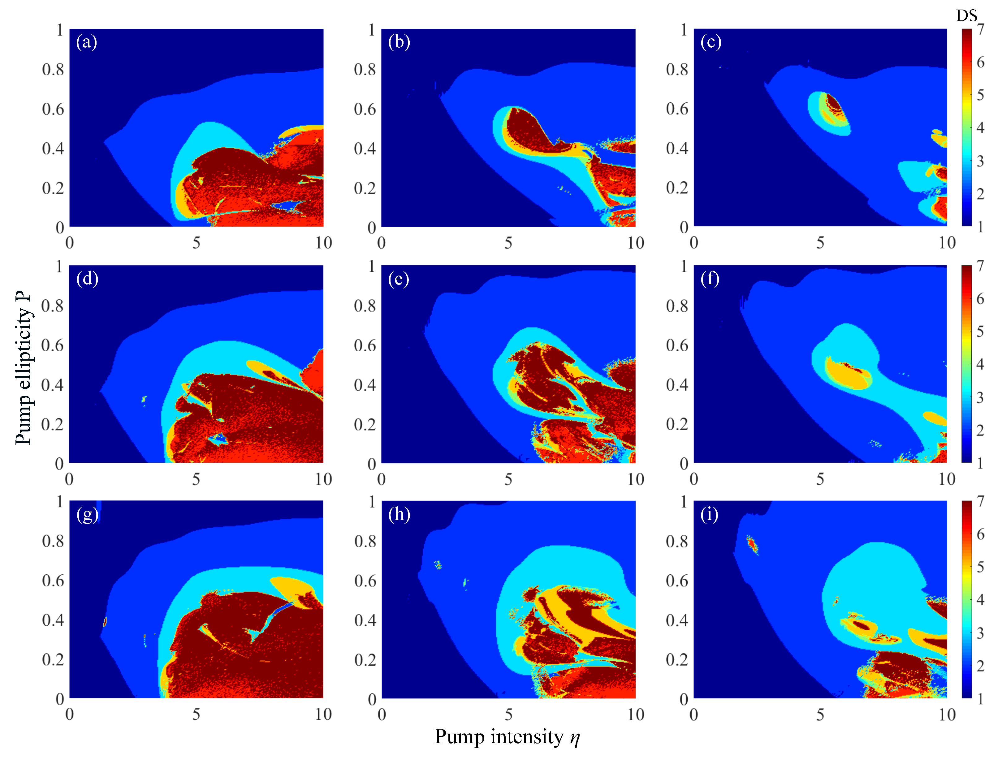
In the cause of further investigation for how optical feedback delay and feedback intensity affect the complicated dynamical regions of nonlinear dynamics, the mapping of the different dynamic states of spin-VCSEL with optical feedback in the parameter space of (, P) under different and k are shown in Figure 6. When the intensity of optical feedback is increased gradually as optical feedback delay is fixed as and 2 respectively, it can be seen from Figure 6d to Figure 6f and Figure 6g to Figure 6i that the regions corresponding to complex dynamics are expanded obviously and the region in steady state (dark blue) shrinks greatly. Noted that due to the existence of feedback strength, P1 surprisingly appears in steady state region at a weak pump intensity and even complex dynamical regions are observed although narrowly. Furthermore, the more expansions of complex dynamics are observed for the larger feedback intensity, such as in Figure 6c,f,i. When optical feedback intensity is set as , , and , correspondingly, through the comparisons of Figure 6d () and Figure 6g (), Figure 6e () and Figure 6h (), Figure 6c (), Figure 6f () and Figure 6i (), it can be concluded that the regions of complex dynamics are also expanded by the increase of optical feedback delay, but the variation of the regions corresponding to complex dynamics is not remarkable for the weak feedback strength such as . Combining the cases where and k are both enhancing, it is obvious that the regions corresponding to more complex dynamics are expanded remarkably in Figure 6i and it is easier to enter into complex dynamics and chaos in a weak pump intensity with stronger feedback strength. Based on the above analysis for mappings in Figure 6, optical feedback as the external perturbation element of spin-VCSELs can realize the more complex dynamical oscillation easily, in which optical feedback delay has a positive effect as well to produce complex dynamical behaviors but the strength of optical feedback plays a relatively dominant role.
Finally, the effects of linewidth enhancement factor and relaxation rate on the size of regions of complex dynamics are also investigated in detail. Corresponding mappings under different and are shown in Figure 7, where the parameters and k in the feedback delay component are set as and respectively. For linewidth enhancement factor , some changes in the region of complex dynamics can be observed from the bifurcation maps of each column in Figure 7. From the comparison among Figure 7a ( and ), Figure 7d ( and ), Figure 7g ( and ), it can be seen that Figure 7g shows the most complex dynamics region in size and its upper limit of oscillation region is expanded observably. Noted that this phenomenon also occurs in other values of , such as and , and it is especially obvious for a larger relaxation rate in Figure 7c,f,i. Distinctly, the regions of P2 and complex dynamics are significantly extended due to the increase of , that is because the amplitude-phase coupling effect is enhanced with a slightly larger value of . Furthermore, by observing the size of the regions of different nonlinear dynamics of each row in Figure 7, it can be concluded that a larger ( in Figure 7c,f,i) can lead to the remarkable size shrink of complex dynamics and chaos regions. Namely, the complicated dynamical regions and chaos region can be shrunken due to the increase of and complex oscillations are easier to achieve for a small relaxation rate. Consequently, it can be summarized that both linewidth enhancement factor and relaxation rate strongly influence the regions of complex dynamics and chaos in size, and decreasing and increasing tend to stabilize the output of spin-VCSELs with optical feedback. The research of mappings has great significance to the expansion of complex dynamic regions of lasers and realize complex dynamical oscillation easily.
4. Conclusions
In summary, based on the presented expanding SFM equations, we have first investigated the nonlinear dynamics of optically pumped spin-VCSELs with optical feedback through numerical simulations. We have demonstrated the effect of some important parameters on the nonlinear dynamical behaviors of the proposed model by the bifurcation analysis, including the intensity of optical feedback, optical feedback delay, linewidth enhancement factor, and relaxation rate in this paper. The mappings of the different dynamic states in the parameter spaces of () and () have been presented from direct numerical simulation to observe the regimes of generated chaos and reveal its rich dynamical regimes intuitively. Furthermore, the characteristics of period, quasiperiodicity, and chaos under the different values of optical feedback intensity and delay are compared in the time series, power spectra, and phase portraits respectively. Correspondingly as supplementary, we employ the 0–1 test to validate the validity of chaos and non-chaos of lasers more intuitively. The results of 0–1 test are consistent with the characteristics of different dynamic states and the corresponding regimes in the mapping, which indicate the effectiveness of our method used to calculate bifurcation maps for spin-VCSELs with optical feedback. The current study can provide potential applications in future optical chaos-based secure communications, image encryption, and biomedical sensing.
Author Contributions
Conceptualization, T.S.; methodology, T.S.; software, T.S.; validation, T.S., B.L., and X.J.; formal analysis, T.S.; investigation, T.S. and Y.Y.; resources, Y.X.; data curation, T.S., Y.Y., and B.L.; writing—original draft preparation, T.S.; writing—review and editing, T.S., Y.X., Y.Y., and Y.Z.; visualization, T.S., Y.Y., and J.C.; supervision, Y.X.; project administration, Y.X.; funding acquisition, Y.X. All authors have read and agreed to the published version of the manuscript.
Funding
This research was funded by the Natural Science Foundation of Chongqing City under Grant cstc2016jcyjA0581 and by the Fundamental Research Funds for the Central Universities under Grant XDJK2018B012.
Data Availability Statement
The data presented in this study are available on request from the corresponding author. The data are not publicly available since the data also forms part of an ongoing study.
Conflicts of Interest
The authors declare no conflict of interest.
References
- San Miguel, M.; Feng, Q.; Moloney, J.V. Light-polarization dynamics in surface-emitting semiconductor lasers. Phys. Rev. A 1995, 52, 1728–1739. [Google Scholar] [CrossRef] [PubMed]
- Gøthgen, C.; Oszwaldowski, R.; Petrou, A.; Zutic, I. Analytical model of spin-polarized semiconductor lasers. Appl. Phys. Lett. 2008, 93, 042513. [Google Scholar] [CrossRef] [Green Version]
- Koyama, F. Recent advances of VCSEL photonics. J. Lightwave Technol. 2006, 24, 4502–4513. [Google Scholar] [CrossRef]
- Gerhardt, N.C.; Hofmann, M.R. Spin-controlled vertical-cavity surface-emitting lasers. Adv. Opt. Technol. 2012, 2012, 268949. [Google Scholar] [CrossRef]
- Nguimdo, R.M.; Verschaffelt, G.; Danckaert, J.; Van der Sande, G. Loss of time-delay signature in chaotic semiconductor ring lasers. Opt. Lett. 2012, 37, 2541–2544. [Google Scholar] [CrossRef]
- Han, H.; Shore, K.A. Dynamical characteristics of nano-lasers subject to optical injection and phase conjugate feedback. IET Optoelectron. 2018, 12, 25–29. [Google Scholar] [CrossRef] [Green Version]
- Li, X.Z.; Li, S.S.; Chan, S.C. Correlated random bit generation using chaotic semiconductor laser under unidirectional optical injection. IEEE Photonics J. 2017, 9, 1505411. [Google Scholar] [CrossRef]
- Zhao, Z.; Cheng, M.; Luo, C.; Deng, L.; Zhang, M.; Fu, S.; Tang, M.; Shum, P.; Liu, D. Synchronized random bit sequences generation based on analog-digital hybrid electro-optic chaotic sources. J. Lightw. Technol. 2018, 36, 4995–5002. [Google Scholar] [CrossRef]
- Sugano, C.; Kanno, K.; Uchida, A. Reservoir computing using multiple lasers with feedback on a photonic integrated circuit. IEEE J. Sel. Top. Quantum Electron. 2020, 26, 1500409. [Google Scholar] [CrossRef]
- Hou, Y.S.; Xia, G.Q.; Yang, W.Y.; Wang, D.; Jayaprasath, E.; Jiang, Z.F.; Hu, C.X.; Wu, Z.M. Prediction performance of reservoir computing system based on a semiconductor laser subject to double optical feedback and optical injection. Opt. Exp. 2018, 26, 10211–10219. [Google Scholar] [CrossRef]
- Argyris, A.; Syvridis, D.; Larger, L.; Annovazzi-Lodi, V.; Colet, P.; Fischer, I.; García-Ojalvo, J.; Mirasso, C.R.; Pesquera, L.; Shore, K.A. Chaos-based communications at high bit rates using commercial fibre-optic links. Nature 2005, 438, 343–346. [Google Scholar] [CrossRef] [PubMed]
- Xie, Y.Y.; Li, J.C.; He, C.; Zhang, Z.D.; Song, T.T.; Xu, C.J.; Wang, G.J. Long-distance multi-channel bidirectional chaos communication based on synchronized VCSELs subject to chaotic signal injection. Opt. Commun. 2016, 377, 1–9. [Google Scholar] [CrossRef]
- Cui, S.; Zhang, J. Chaotic secure communication based on single feedback phase modulation and channel transmission. IEEE Photonics J. 2019, 11, 7905208. [Google Scholar] [CrossRef]
- Li, N.Q.; Susantu, H.; Cemlyn, B.; Henning, I.D.; Adams, M.J. Secure communication systems based on chaos in optically pumped spin-VCSELs. Opt. Lett. 2017, 42, 3494–3497. [Google Scholar] [CrossRef]
- Lin, F.Y.; Liu, J.M. Chaotic lidar. IEEE J. Sel. Top. Quantum Electron. 2004, 10, 991–997. [Google Scholar] [CrossRef]
- Wang, L.; Guo, Y.; Li, P.; Zhao, T.; Wang, Y.; Wang, A. White-chaos radar with enhanced range resolution and anti-jamming capability. IEEE Photon. Technol. Lett. 2017, 29, 1723–1726. [Google Scholar] [CrossRef]
- Zhou, P.; Li, N.Q.; Pan, S.L. Photonic microwave harmonic down-converter based on stabilized period-one nonlinear dynamics of semiconductor lasers. Opt. Lett. 2019, 44, 4869–4872. [Google Scholar] [CrossRef]
- Xia, L.; Huang, D.; Xu, J.; Liu, D. Simultaneous and precise fault locating in WDM-PON by the generation of optical wideband chaos. Opt. Lett. 2013, 38, 3762–3764. [Google Scholar] [CrossRef]
- Rontani, D.; Choi, D.; Chang, C.Y.; Locquet, A.; Citrin, D.S. Compressive sensing with optical chaos. Sci. Rep. 2016, 6, 35206. [Google Scholar] [CrossRef] [Green Version]
- Adams, M.J.; Alexandropoulos, D. Parametric analysis of spin-polarized VCSELs. IEEE J. Quantum Electron. 2009, 45, 744–749. [Google Scholar] [CrossRef]
- Torre, M.S.; Susanto, H.; Li, N.Q.; Schires, K.; Salvide, M.F.; Henning, I.D.; Adams, M.J.; Hurtado, A. High frequency continuous birefringence-induced oscillations in spin-polarized vertical-cavity surface-emitting lasers. Opt. Lett. 2017, 42, 1628–1631. [Google Scholar] [CrossRef] [PubMed] [Green Version]
- Oestreich, M.; Hubner, J.; Hagele, D.; Bender, M.; Gerhardt, N.; Hofmann, M.; Ruhle, W.W.; Kalt, H.; Hartmann, T.; Klar, P.; et al. Spintronics: Spin electronics and optoelectronics in semiconductors. Adv. Solid State Phys. 2001, 41, 173–186. [Google Scholar]
- Lindemann, M.; Xu, G.; Pusch, T.; Michalzik, R.; Hofmann, M.R.; Žutić, I.; Gerhardt, N.C. Ultrafast spin-lasers. Nature 2019, 568, 212–215. [Google Scholar] [CrossRef]
- Gerhardt, N.C.; Li, M.Y.; Jähme, H.; Höpfner, H.; Ackemann, T.; Hofmann, M.R. Ultrafast spin-induced polarization oscillations with tunable lifetime in vertical-cavity surface-emitting lasers. Appl. Phys. Lett. 2011, 99, 151107. [Google Scholar] [CrossRef]
- Yokota, N.; Nisaka, K.; Yasaka, H.; Ikeda, K. Spin polarization modulation for high-speed vertical-cavity surface-emitting lasers. Appl. Phys. Lett. 2018, 113, 171102. [Google Scholar] [CrossRef]
- Lindemann, M.; Xu, G.; Pusch, T.; Michalzik, R.; Hofmann, M.R.; Žutić, I.; Gerhardt, N.C. Ultrafast Spin-Lasers for Optical Data Communication. In Proceedings of the 2019 Conference on Lasers and Electro-Optics Europe & European Quantum Electronics Conference, Munich, Germany, 23–27 January 2019; p. 19148647. [Google Scholar]
- Hövel, S.; Gerhardt, N.C.; Brenner, C.; Hofmann, M.R.; Lo, F.-Y.; Reuter, D.; Wieck, A.D.; Schuster, E.; Keune, W. Spin-controlled LEDs and VCSELs. Phys. Stat. Sol. (A) 2007, 204, 500–507. [Google Scholar] [CrossRef]
- Holub, M.; Shin, J.; Saha, D.; Bhattacharya, P. Electrical spin injection and threshold reduction in a semiconductor laser. Phys. Rev. Lett. 2007, 98, 146603. [Google Scholar] [CrossRef] [PubMed]
- Fujino, H.; Koh, S.; Iba, S.; Fujimoto, T.; Kawaguchi, H. Circularly polarized lasing in a (110)-oriented quantum well vertical-cavity surface-emitting laser under optical spin injection. Appl. Phys. Lett. 2009, 94, 131108. [Google Scholar] [CrossRef]
- Gahl, A.; Balle, S.; San Miguel, M. Polarization dynamics of optically pumped VCSELs. IEEE J. Quantum Electron. 1999, 35, 342–351. [Google Scholar] [CrossRef]
- Susanto, H.; Schires, K.; Adams, M.J.; Henning, I.D. Spin-flip model of spin-polarized vertical-cavity surface-emitting lasers: Asymptotic analysis, numerics, and experiments. Phys. Rev. A 2015, 92, 063838. [Google Scholar] [CrossRef] [Green Version]
- Alharthi, S.S.; Al Seyab, R.K.; Henning, I.D.; Adams, M.J. Simulated dynamics of optically pumped dilute nitride 1300 nm spin vertical-cavity surface-emitting lasers. IET Optoelectron. 2014, 8, 117–121. [Google Scholar] [CrossRef] [Green Version]
- Al Seyab, R.K.; Alexandropoulos, D.; Henning, I.D.; Adams, M.J. Instabilities in spin-polarized vertical-cavity surface-emitting lasers. IEEE Photonics J. 2011, 3, 799–809. [Google Scholar] [CrossRef]
- Li, N.Q.; Susanto, H.; Cemlyn, B.R.; Henning, I.D.; Adams, M.J. Stability and bifurcation analysis of spin-polarized vertical-cavity surface-emitting lasers. Phys. Rev. A 2017, 96, 013840. [Google Scholar] [CrossRef] [Green Version]
- Li, N.Q.; Alexandropoulos, D.; Susanto, H.; Henning, I.D.; Adams, M.J. Stability analysis of quantum-dot spin-VCSELs. Electronics 2016, 5, 83. [Google Scholar] [CrossRef] [Green Version]
- Alexandropoulos, D.; Al-Seyab, R.; Henning, I.D.; Adams, M.J. Instabilities in quantum-dot spin-VCSELs. Opt. Lett. 2012, 37, 1700–1702. [Google Scholar] [CrossRef]
- Li, N.Q.; Susanto, H.; Cemlyn, B.R.; Henning, I.D.; Adams, M.J. Mapping bifurcation structure and parameter dependence in quantum dot spin-VCSELs. Opt. Exp. 2018, 26, 14636–14649. [Google Scholar] [CrossRef]
- Masoller, C.; Torre, M.S. Influence of optical feedback on the polarization switching of vertical-cavity surface-emitting lasers. IEEE J. Quantum Electron. 2005, 41, 483–489. [Google Scholar] [CrossRef]
- Panajotov, K.; Sciamanna, M.; Arteaga, M.A.; Thienpont, H. Optical feedback in vertical-cavity surface-emitting lasers. IEEE J. Sel. Top. Quantum Electron. 2013, 19, 1700312. [Google Scholar] [CrossRef]
- Globisch, B.; Otto, C.; Schöll, E.; Lüdge, K. Influence of carrier lifetimes on the dynamical behavior of quantum-dot lasers subject to optical feedback. Phys. Rev. E 2012, 86, 046201. [Google Scholar] [CrossRef]
- Xia, G.Q.; Chan, S.C.; Liu, J.M. Multistability in a semiconductor laser with optoelectronic feedback. Opt. Express 2007, 15, 572–576. [Google Scholar] [CrossRef]
- Lin, F.Y.; Liu, J.M. Nonlinear dynamics of a semiconductor laser with delayed negative optoelectronic feedback. IEEE J. Quantum Electron. 2003, 39, 562–568. [Google Scholar] [CrossRef]
- Xie, Y.Y.; Lin, X.D.; Deng, T.; Wu, Z.M.; Fan, L.; Zhong, Z.Q.; Xia, G.Q. Experimental observation of current-induced bistability in a semiconductor laser with positive optoelectronic feedback. IEEE Photonics Technol. Lett. 2012, 24, 1434–1436. [Google Scholar] [CrossRef]
- Xie, Y.Y.; Che, H.J.; Zhao, W.L.; Huang, Y.X.; Xu, W.H.; Li, X.; Kan, Q.; Li, J.C. Dynamics of 1550-nm VCSELs with positive optoelectronic feedback: Theory and experiments. IEEE Photonics J. 2014, 6, 1502508. [Google Scholar] [CrossRef]
- Li, Q.L.; Lu, S.S.; Bao, Q.; Chen, D.W.; Hu, M.; Zeng, R.; Yang, G.W.; Li, S.Q. Simultaneous trilateral communication based on three mutually coupled chaotic semiconductor lasers with optical feedback. Appl. Opt. 2018, 57, 251–257. [Google Scholar] [CrossRef]
- Jiang, N.; Pan, W.; Yan, L.S.; Luo, B.; Zou, X.H.; Xiang, S.Y.; Yang, L.; Zheng, D. Multiaccess optical chaos communication using mutually coupled semiconductor lasers subjected to identical external injections. IEEE Photonics Technol. Lett. 2010, 22, 676–678. [Google Scholar] [CrossRef]
- Yokota, N.; Komukai, K.; Yoshida, M.; Yasaka, H. Numerical investigation of mutually injection-locked semiconductor lasers for direct IQ-signal generation. IEEE Photonics J. 2019, 11, 6602611. [Google Scholar] [CrossRef]
- Torre, M.S.; Masoller, C.; Shore, K.A. Numerical study of optical injection dynamics of vertical-cavity surface-emitting lasers. IEEE J. Quantum Electron. 2004, 40, 25–30. [Google Scholar] [CrossRef]
- Jiang, Z.F.; Wu, Z.M.; Jayaprasath, E.; Yang, W.Y.; Hu, C.X.; Xia, G.Q. Nonlinear dynamics of exclusive excited-state emission quantum dot Lasers under optical injection. Photonics 2019, 6, 58. [Google Scholar] [CrossRef] [Green Version]
- Mu, P.H.; Pan, W.; Li, N.Q. Analysis and characterization of chaos generated by free-running and optically injected VCSELs. Opt. Express 2018, 26, 15642–15655. [Google Scholar] [CrossRef]
- Correa-Mena, A.G.; Lee, M.W.; Zaldívar-Huerta, I.E.; Hong, Y.; Boudrioua, A. Investigation of the dynamical behavior of a high-power laser diode subject to stimulated brillouin scattering optical feedback. IEEE J. Quantum Electron. 2020, 56, 2000406. [Google Scholar] [CrossRef]
- Hohl, A.; Gavrielides, A. Bifurcation cascade in a semiconductor laser subject to optical feedback. Phys. Rev. Lett. 1999, 82, 1148–1151. [Google Scholar] [CrossRef]
- Haegeman, B.; Engelborghs, K.; Roose, D. Stability and rupture of bifurcation bridges in semiconductor lasers subject to optical feedback. Phys. Rev. E 2002, 66, 046216. [Google Scholar] [CrossRef] [PubMed] [Green Version]
- Gottwald, G.A.; Melbourne, I. A new test for chaos in deterministic systems. In Proceedings of the Royal Society A: Mathematical Physical and Engineering Sciences, London, UK, 8 February 2004; pp. 603–611. [Google Scholar]
- Hu, J.; Tung, W.W.; Gao, J.B.; Cao, Y.H. Reliability of the 0–1 test for chaos. Phys. Rev. E 2005, 72, 056207. [Google Scholar] [CrossRef] [PubMed] [Green Version]
- Erzgräber, H.; Wieczorek, S.; Krauskopf, B. Dynamics of two semiconductor lasers coupled by a passive resonator. Phys. Rev. E 2010, 81, 056201. [Google Scholar] [CrossRef] [Green Version]
- Zachilas, L.; Psarianos, I.N. Examining the chaotic behavior in dynamical systems by means of the 0–1 test. J. Appl. Math. 2012, 2012, 681296. [Google Scholar] [CrossRef]
- Leon, F. Design and evaluation of a multiagent interaction protocol generating behaviours with different levels of complexity. Neurocomputing 2014, 146, 173–186. [Google Scholar] [CrossRef]
- Gottwald, G.A.; Melbourne, I. The 0–1 test for chaos: A review. In Chaos Detection and Predictability; Springer: Berlin, Germany, 2016; pp. 221–247. [Google Scholar]
- Krese, B.; Govekar, E. Nonlinear analysis of laser droplet generation by means of 0–1 test for chaos. Nonlinear Dyn. 2012, 67, 2101–2109. [Google Scholar] [CrossRef]
- Gottwald, G.A.; Melbourne, I. Implementation of the 0–1 test for chaos. SIAM J. Appl. Dyn. Syst. 2009, 8, 129–145. [Google Scholar] [CrossRef]
Figure 1.
Schematic diagram of spin-VCSEL with optical feedback.
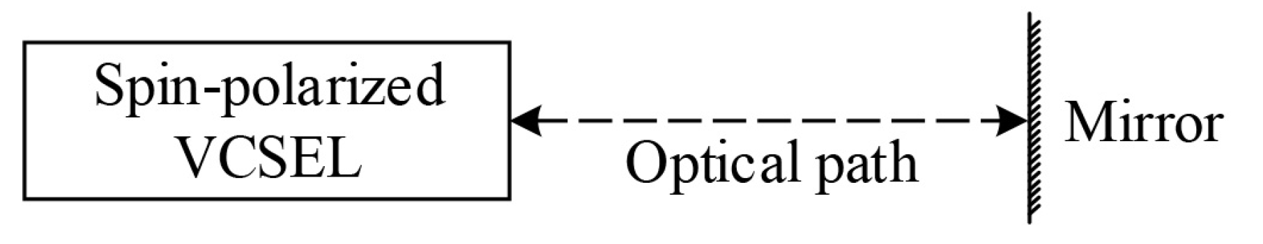
Figure 2.
Bifurcation diagrams of the RCP intensity extrema versus optical feedback coefficient k: (a) ; (b) ; (c) ; (d) .
Figure 2.
Bifurcation diagrams of the RCP intensity extrema versus optical feedback coefficient k: (a) ; (b) ; (c) ; (d) .

Figure 3.
Mapping of the different dynamic states (DSs) of spin-VCSEL with optical feedback in the parameter space of (, k), in which the other parameters are the same as in the basic set of model parameters. 1: steady state; 2: P1; 3: P2; 4, 5: multi-period; 6, 7: chaos pulsation.
Figure 3.
Mapping of the different dynamic states (DSs) of spin-VCSEL with optical feedback in the parameter space of (, k), in which the other parameters are the same as in the basic set of model parameters. 1: steady state; 2: P1; 3: P2; 4, 5: multi-period; 6, 7: chaos pulsation.
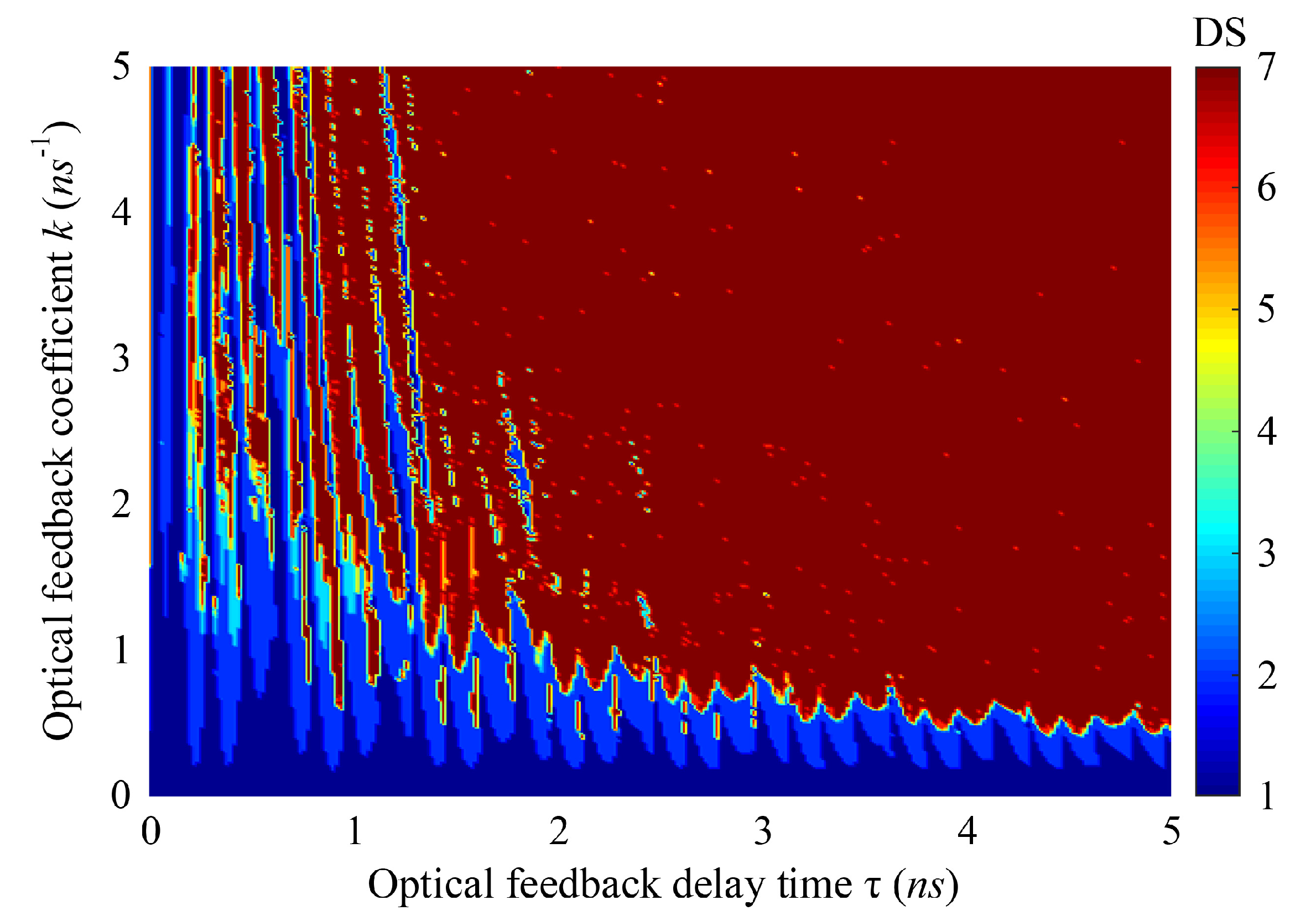
Figure 4.
Numerically simulated time series, power spectra, and phase portraits of the proposed model in different dynamic states, where and (a) ; (b) ; (c) ; (d) and .
Figure 4.
Numerically simulated time series, power spectra, and phase portraits of the proposed model in different dynamic states, where and (a) ; (b) ; (c) ; (d) and .

Figure 5.
The 0–1 test for observing the different dynamic states, where and (a) ; (b) ; (c) ; (d) and . The parameters in this figure are the same as in Figure 4. K: asymptotic growth rate; M: mean square displacement; p and q: translation variables; c: random constant; t: sampled data.
Figure 5.
The 0–1 test for observing the different dynamic states, where and (a) ; (b) ; (c) ; (d) and . The parameters in this figure are the same as in Figure 4. K: asymptotic growth rate; M: mean square displacement; p and q: translation variables; c: random constant; t: sampled data.
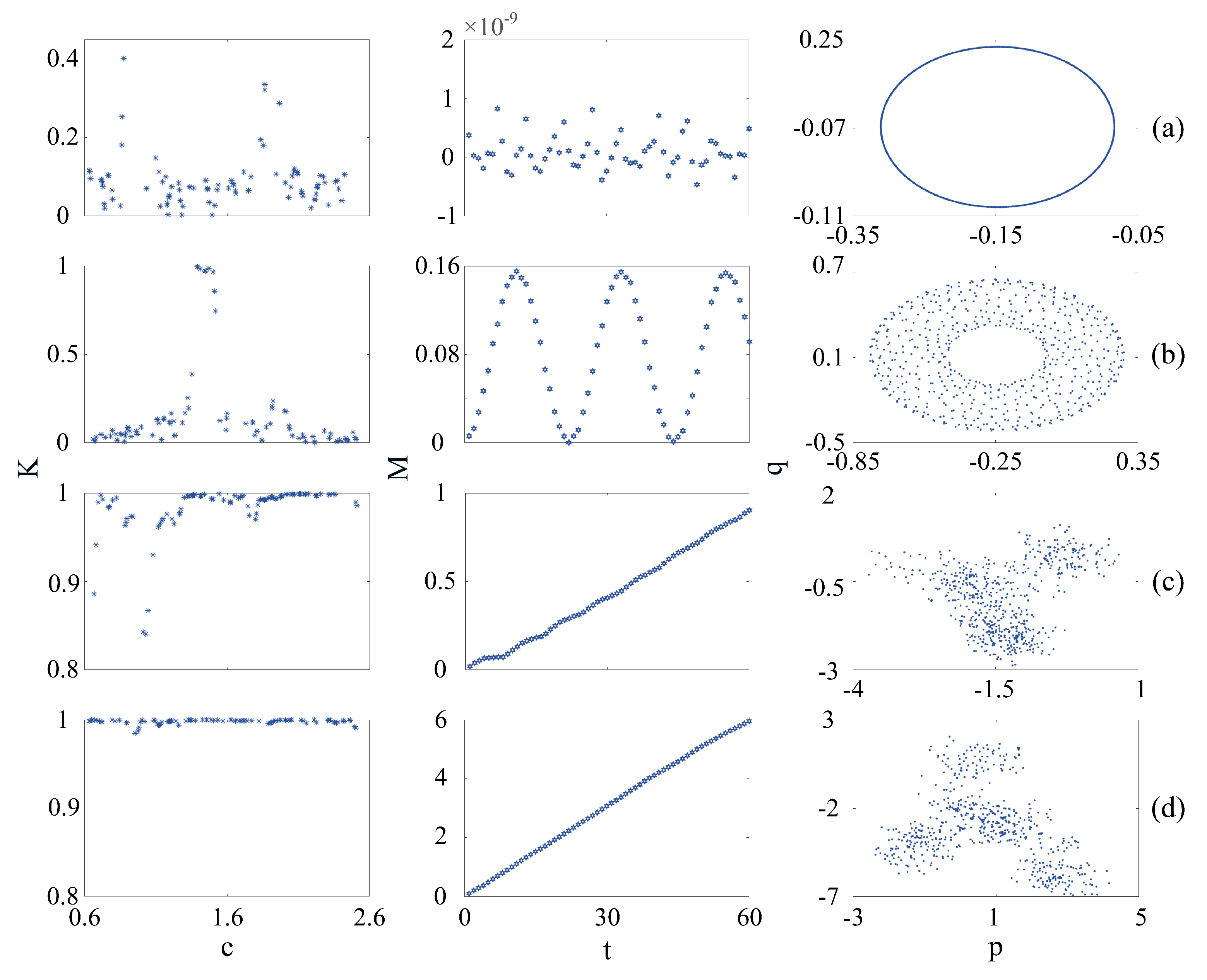
Figure 6.
Mapping of the different dynamic states of spin-VCSEL with optical feedback in the parameter space of (, P), in which (a) , ; (b) , ; (c) , ; (d) , ; (e) , ; (f) , ; (g) , ; (h) , ; (i) , . The other parameters are the same as those given in the preceding discussion. 1: steady state; 2: P1; 3: P2; 4, 5: multi-period; 6, 7: chaos pulsation.

Figure 7.
Mapping of the different dynamic states of spin-VCSEL with optical feedback in the parameter space of (, P) with and , where (a) , ; (b) , ; (c) , ; (d) , ; (e) , ; (f) , ; (g) , ; (h) , ; (i) , . The other parameters are the same as those given in the preceding discussion. 1: steady state; 2: P1; 3: P2; 4, 5: multi-period; 6, 7: chaos pulsation.
Publisher’s Note: MDPI stays neutral with regard to jurisdictional claims in published maps and institutional affiliations. |
© 2021 by the authors. Licensee MDPI, Basel, Switzerland. This article is an open access article distributed under the terms and conditions of the Creative Commons Attribution (CC BY) license (http://creativecommons.org/licenses/by/4.0/).
Share and Cite
MDPI and ACS Style
Song, T.; Xie, Y.; Ye, Y.; Liu, B.; Chai, J.; Jiang, X.; Zheng, Y. Numerical Analysis of Nonlinear Dynamics Based on Spin-VCSELs with Optical Feedback. Photonics 2021, 8, 10. https://doi.org/10.3390/photonics8010010
AMA Style
Song T, Xie Y, Ye Y, Liu B, Chai J, Jiang X, Zheng Y. Numerical Analysis of Nonlinear Dynamics Based on Spin-VCSELs with Optical Feedback. Photonics. 2021; 8(1):10. https://doi.org/10.3390/photonics8010010
Chicago/Turabian StyleSong, Tingting, Yiyuan Xie, Yichen Ye, Bocheng Liu, Junxiong Chai, Xiao Jiang, and Yanli Zheng. 2021. "Numerical Analysis of Nonlinear Dynamics Based on Spin-VCSELs with Optical Feedback" Photonics 8, no. 1: 10. https://doi.org/10.3390/photonics8010010
Note that from the first issue of 2016, this journal uses article numbers instead of page numbers. See further details here.