Photonics-Based Microwave Image-Reject Mixer


The Key Laboratory of Radar Imaging and Microwave Photonics, Ministry of Education, Nanjing University of Aeronautics and Astronautics, Nanjing 210016, China
*
Author to whom correspondence should be addressed.
Photonics 2018, 5(2), 6; https://doi.org/10.3390/photonics5020006
Submission received: 12 February 2018
/
Revised: 19 March 2018
/
Accepted: 22 March 2018
/
Published: 26 March 2018
(This article belongs to the Special Issue Microwave Photonics 2017)
Abstract
:Recent developments in photonics-based microwave image-reject mixers (IRMs) are reviewed with an emphasis on the pre-filtering method, which applies an optical or electrical filter to remove the undesired image, and the phase cancellation method, which is realized by introducing an additional phase to the converted image and cancelling it through coherent combination without phase shift. Applications of photonics-based microwave IRM in electronic warfare, radar systems and satellite payloads are described. The inherent challenges of implementing photonics-based microwave IRM to meet specific requirements of the radio frequency (RF) system are discussed. Developmental trends of the photonics-based microwave IRM are also discussed.
1. Introduction
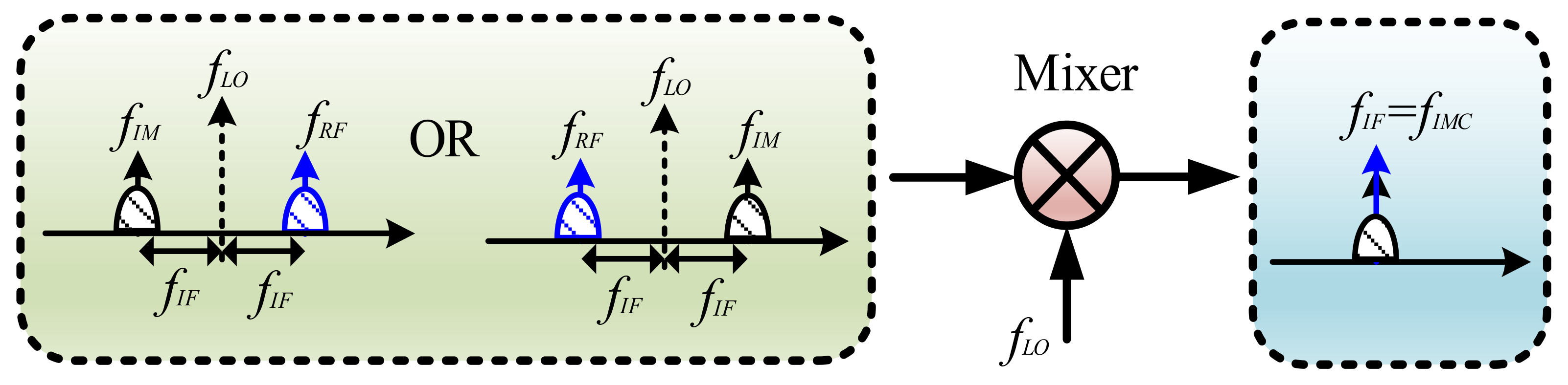
A frequency mixer is an essential module in modern microwave systems, such as radar, electronic warfare, wireless communication devices and satellite payloads [1,2,3,4]. Frequency mixers facilitate frequency upconversion to generate a radio frequency (RF) signal at fRF = |fIF + fLO|, where fIF and fLO are the frequencies of the intermediate frequency (IF) signal and local oscillator (LO) signal, respectively. Frequency mixers also facilitate frequency downconversion to generate an IF signal, described as fIF = |fRF − fLO|. In recent years, the frequency mixers implemented, based on microwave photonic technologies, have attracted great interest due to advantages such as their large bandwidth, light weight, high isolation and electromagnetic interference immunity (EMI) [5,6,7]. In addition, the photonics-based microwave frequency mixer can be combined with radio over fiber (RoF) technology to realize remote fiber-optic antennas, avoiding any additional electrical-to-optical or optical-to-electrical conversion [8,9]. However, the photonic microwave mixer is usually implemented through a heterodyne structure to obtain a nonzero IF signal, which can be easily interfered with by image signals. As shown in Figure 1, the image signal at fIM, with a frequency above or below the LO frequency by an amount equal to IF, will be converted to the same IF band, together with the desired IF signal downconverted from the radio frequency (RF) signal at fRF. Thus the downconverted image cannot be removed by filtering due to spectrum aliasing. Image-reject mixer (IRM) is a downconverter with a large suppression of downconverted products (fIMC = |fIM − fLO|) resulting in undesired image signal fIM while maintaining or enhancing the desired component. Typical electrical IRM structure is shown and analyzed in [10]. Due to electronic bottleneck, the working frequency and bandwidth are limited for electrical IRMs (i.e., IF bandwidth limited to no more than 160 MHz, and LO frequency limited to no higher than 14.0–18.0 GHz) [11]. For future RF systems, RF signals with large bandwidth will be used and systems will be operated in a complicated electromagnetic environment. Thus, image distortions will be serious, which creates an urgent demand for high performance photonics-based microwave IRM.
In this paper, we review recent developments in photonics-based microwave IRM with an emphasis on the pre-filtering method [12,13,14,15,16,17] and the phase cancellation method [18,19,20,21,22,23,24,25,26,27,28,29,30]. Applications of photonics-based microwave IRMs in electronic warfare, radars, satellite communications, and so on, are described [31,32,33,34,35,36,37,38,39,40,41,42,43], with challenges in implementing photonics-based microwave IRMs to meet the requirements of RF systems. Finally, development trends of the photonics-based microwave IRM are discussed.
2. Photonic IRMs Based on Pre-Filtering
A typical way to achieve image rejection is to directly remove the image from the input RF signal by a filter, either in the electrical [12] or optical domain [13], as shown in Figure 2. As can be seen from Figure 2c, the performance of the image rejection depends on the response of the filter. For a scenario using an electrical bandpass filter (EBPF), to select the required RF signal, as shown in Figure 2a, electrical filters with high center frequency will be required to realize high frequency operation capabilities of IRMs. In addition, the slope of the filter must be sharp enough to suppress the image without affecting the desired signal, especially when the IF frequency is very low (i.e., the frequency difference between fRF and fIM is small). For example, the EBPF used in [12] has a passband of 8–9 GHz, thus, instantaneous working bandwidth is limited to 1 GHz. For a required IF working frequency (10 GHz [12]), the RF/LO working frequency will also be limited by the EBPF (20 GHz in [12]). When using an optical bandpass filter (OBPF) to select the required modulated RF signal in the optical domain, as shown in Figure 2b, optical filters with narrow bandwidth and sharp edge roll-offs are desirable. However, both the electrical filters with high center frequency, and optical filters with narrow bandwidth and sharp edge roll-offs, are difficult to realize, limiting working bandwidth and system performance. For example, the optical filter described by Strutz and Williams, [13] is a Fabry-Perot filter with a 3-dB bandwidth of 0.6 GHz, which is too wide for many applications. In addition, the filter bandwidths and center frequencies are usually fixed and wide tunability is hard to realize, limiting the flexibility of the system.
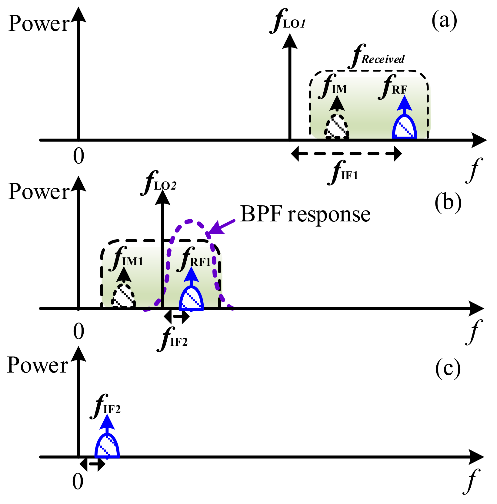
To solve these problems, another method using pre-filtering was realized, based on multiple-stage frequency conversion [14,15,16,17]. Figure 3 shows a schematic diagram of typical IRMs based on multiple-stage frequency conversion, and Figure 4 illustrates its principle. The original RF signal fReceived (containing the image fIM) shown in Figure 4a is first downconverted using LO1 at a photonics-based microwave mixer. The converted result is shown in Figure 4b. Then a bandpass filter is used to select the desired RF signal and to remove the undesired image, as shown in Figure 4b. The selected RF signal enters the second photonics-based microwave mixer and is downconverted using LO2 to the desired IF band. The final downconverted result is shown in Figure 4c. As compared with the IRM based on direct pre-filtering, shown in Figure 2c, frequency requirement of the EBPF is lowered by increasing the number of frequency-conversion stages. Thus, when filtering is performed in the electrical domain after optical-to-electrical conversion, a good image rejection can be realized. It should be noted that in the first frequency-conversion step, one can carefully select LO1 frequency to downconvert received RF signal into a proper band, where EBPF with narrow bandwidth and sharp edge roll-offs is easy to achieve [14,15]. For example, an image-rejection ratio of larger than 150 dB has been achieved by Strutz and Williams [14] using two cascaded EBPFs with large out-of-band suppression, and in another paper [15] the image-rejection ratio reached 60 dB when the EBPF out-of-band suppression was 60 dB. Filtering after the first-stage frequency conversion can also be realized in the optical domain [16,17]. When using optical filters, achieving adequate edge sharpness and frequency-/bandwidth-tuning is still challenging. In addition, because the multiple-stage frequency conversion needs multiple LO sources, the system always has a complex structure with large volume and high cost.
For photonic IRMs based on pre-filtering, one trend has been to involve microwave photonic filters [44,45], which are designed to undertake equivalent tasks to those of microwave filters. However, it is hoped that these IRMs will introduce advantages brought by photonics, such as low loss, high bandwidth, EMI, tunability, and reconfigurability.
3. Photonic IRM Based on Phase-Cancellation Techniques
Phase-cancellation technique is another way to realize photonics-based microwave IRMs [18,19,20,21,22,23,24,25,26,27,28,29,30], also known as Hartley architecture. Figure 5 shows the principle method. A pair of quadrature LO (or RF) signals are introduced to generate two quadrature IF outputs, which are then combined by a low-frequency 90-degree hybrid, introducing an additional 90° phase difference, to make the downconverted image out of phase, and those downconverted from the wanted RF signals in phase. In this way, the wanted IF signals are enhanced, while the downconverted image at the same band is cancelled. Since this kind of photonics-based microwave IRM uses the phase differences of the signals to realize the image rejection, any requirement of filtering or multi-stage frequency conversion is avoided. In addition, when the RF signal frequency changes, the IRM based on phase cancellation can still suppress the corresponding image, which enables broadband applications. Three typical IRM schemes based on phase cancellation were proposed, using 90° electrical hybrid, microwave photonic phase shifters, and optical 90° hybrid.
3.1. Photonic IRMs Based on 90° Electrical Hybrid
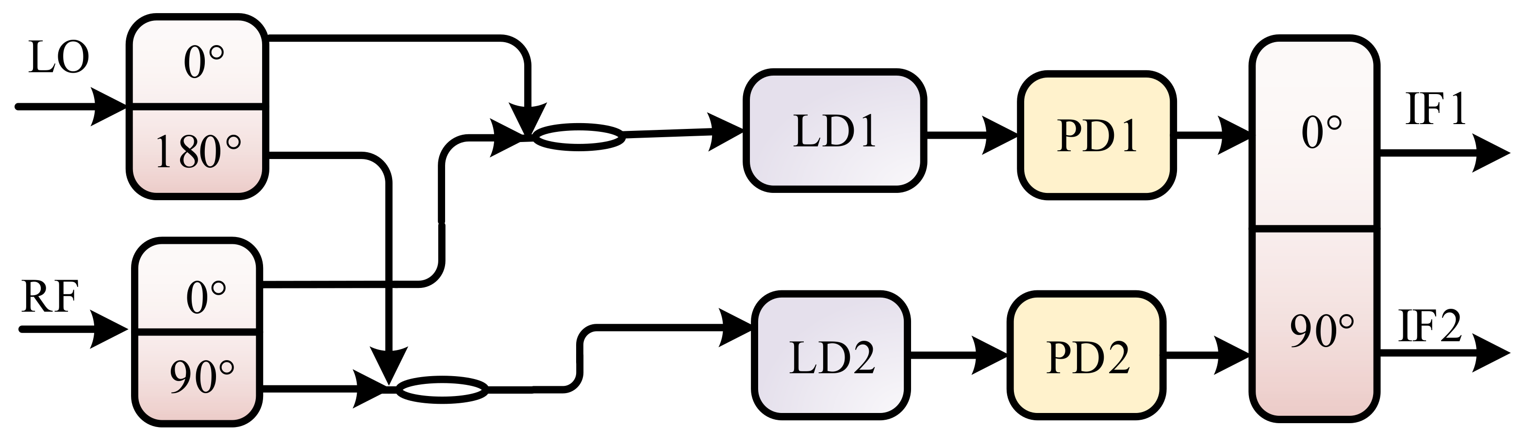
Methods in the first category apply an electrical 90° hybrid to generate a pair of quadrature LOs [18] or a pair of quadrature RF signals (containing the images) [19,20]. Then, RF and LO signals are mixed in the optical domain. A pair of quadrature IF outputs will be generated, which are combined by another electrical 90° hybrid, to produce a downconverted IF signal, with the downconverted image being rejected. In Lu et al.’s paper [18], the in-phase RF signals were modulated on two lasers by direct modulation, and then injected into two separate electro-optic modulators driven by the pair of quadrature LOs from an electrical 90° hybrid. A separate study [19] describes two quadrature RF signals being generated by an electrical 90° hybrid, and two out-of-phase LOs being produced by an out-of-phase divider, that formed two RF and LO pairs, which were mixed at two directly modulated lasers. Optical signals output from the two lasers were detected by two photodetectors (PDs), generating a pair of quadrature IFs. The two IFs are then combined by another electrical quadrature hybrid to achieve image-reject downconversion. For both approaches, two mixed RF and LO pairs were separated, and the difference between two separated branches affected the system performance and stability. By using integrated modulators to perform modulation by the LO and RF signals simultaneously, this problem can be avoided. For example, a single integrated dual-parallel Mach-Zehnder modulator (DPMZM) has been previously used [20], which greatly improved the stability of the system. The key problem associated with approaches in this category [18,19,20] is that they rely on an electrical 90° hybrid to generate quadrature RF signals or LOs. Since electrical 90° hybrids cannot maintain a precise 90° phase difference across a wide frequency range at high frequencies, the bandwidth of IRMs is usually very limited, or, the image suppression ratio is small (Figure 6).
3.2. IRMs Based on Microwave Photonic Phase Shifters
To avoid using the high-frequency electrical 90° hybrid, photonic IRMs based on microwave photonic phase shifters were proposed [21,22,23,24], since the microwave photonic phase shifters can realize a 90-degree phase difference across a wide frequency range at high frequencies. The key component is an advanced modulator with two sub-modulators, which can be implemented by a dual-polarization dual-drive Mach-Zehnder modulator (DPol-MZM) [21], a DPMZM [22,23], or a polarization-division multiplexing Mach-Zehnder modulator [24]. Each sub-modulator (i.e., a sub-dual-drive Mach-Zehnder modulator (sub-DMZM) [21], and a sub-Mach-Zehnder modulator (sub-MZM) [22,23,24]) performs single-ended mixing. Meanwhile, together with optical filters, photonic microwave phase shift was achieved with a phase shift controlled by either bias voltages of the sub-modulators [21,22,23], or the polarization state at the output of the modulator [24]. Thus, a precise 90-degree phase shift over a wide frequency range can be introduced between two parallel single-ended mixers (i.e., two sub-modulators). After photodetection, quadrature IFs are combined by low-frequency electrical quadrature hybrid to realize image rejection. An image-rejection ratio as high as 60 dB is realized when RF/LO frequency is tuned from 10 to 40 GHz [21]. However, system stability is affected by bias drift or polarization fluctuation, because phase shift is controlled by the bias voltages [21,22,23] or polarization state [24]. Additionally, although optical filters can remove most undesirable sidebands, leading to large suppression of the mixing spurs [21], their limited edge roll-offs could restrict IRM performance at a low frequency regime.
3.3. Photonic IRM Based on 90° Optical Hybrid
The third class of photonic IRMs based on phase cancellation applies a 90° optical hybrid to introduce a quadrature phase [25,26,27,28,29]. Benefiting from a simple structure and the small phase imbalance of the commercially available optical hybrid over a wide frequency range, a high image rejection ratio can be achieved in a large bandwidth. Figure 7 shows a schematic diagram of a typical IRM based on a 90° optical hybrid [25]. The optical carrier is split into two branches. One branch is modulated by an RF signal and the other is modulated by an LO signal, both with carrier-suppressed single-sideband (CS-SSB) modulation. The CS-SSB modulation can be realized by using either optical filters placed in each branch [25,26,27], or I/Q modulators operated at CS-SSB mode [28,29]. Signals from the two branches are sent to the signal port and the LO port of the 90° optical hybrid, which typically has two in-phase output and two quadrature output ports. When one of the in-phase outputs and one of the quadrature outputs are sent to two PDs, an I/Q frequency mixer is obtained. By using a low-frequency electrical quadrature hybrid to combine the two electrical outputs of the I/Q mixer, a photonic IRM is achieved. It should be noted that if other outputs of the 90° optical hybrid are directed to PDs, single-ended and balanced mixers can also be realized.
Since parallel modulations, and/or parallel filterings, and parallel amplifications are required to obtain the independent RF and LO sidebands, the system performance will therefore be vulnerable to any path length difference between the two branches [26,27,28,29]. Therefore, environmental vibration, which cause path length variations, would be a challenge for practical application of such IRMs. To overcome this problem, in [26] a reconfigurable microwave photonic mixer which can perform such functions, including the IRM, is achieved by using a DPol-MZM and an optical 90° hybrid. Parallel signal modulations are implemented in an integrated modulator and act as polarization multiplexors at the output. Thus, RF and LO sidebands can both be filtered and amplified by the same devices, guaranteeing links consistency for both signals. Separation lengths are minimized, which can be easily packaged to avoid environmental vibration.
With the three aforementioned kinds of photonic IRMs, based on phase-cancellation techniques, images can be rejected over a wide frequency range. On the other hand, mixing spurs are generated by the nonlinearity of the mixer at frequencies of |kfRF + lfLO|, where k and l are integers. Since the mixing spurs might be in the same band of the wanted signal, especially in a wideband operation scenario, they should be suppressed together with the image. To realize mixing-spur suppression, we can rely on advanced modulation formats. For example, the suppression of LO/RF leakages can be realized by introducing a carrier suppressed double sideband (CS-DSB) modulation format for both RF and LO signals [20]. In addition, a CS-SSB modulation format can be applied to eliminate more high-frequency spurs [21,22,23,24,25,26,27,28,29]. However, the implementation of advanced modulation formats always requires complex configuration, and typically needs optical filters or high-frequency electrical hybrids, which can limit working frequency range. In addition, the previously reported photonics-based microwave IRMs are tested and analyzed by respectively injecting an RF signal and image. In practical applications, RF signals and images are received simultaneously and will generate other unwanted mixing spurs. For example, beating between RF and image signals will generate mixing spurs of the 2nd-order harmonic downconverted IF signal at 2fIF, which is very close to the optimum IF signal at fIF. Thus, this beating is difficult to remove through filtering. For wideband applications, mixing spurs at 2fIF can overlap with the desired IF signal at fIF.
To deal with this problem, in one of our recent works, a photonic IRM based on a 90° optical hybrid and two balanced photodetectors (BPDs) was proposed and demonstrated [30], which could suppress mixing spurs of RF and image signals. The RF signal (containing the image) and electrical LO signal are both converted into the optical domain and then injected into the signal and LO ports of a 90° optical hybrid, respectively. The 90° optical hybrid introduces a 180° phase difference into the optical LO for two in-phase and the quadrature optical outputs. Through optical to electrical conversion, the IF electrical outputs for two in-phase optical outputs (or two quadrature optical outputs) at fIF are out of phase, while the other mixing spurs are in-phase. Thus, by injecting two in-phase and two quadrature optical outputs into two BPDs, respectively, at the output of each BPD the mixing spurs will be suppressed. In addition, the two IF outputs, from the two BPDs, are quadrature because the 90° optical hybrid also introduces a quadrature phase of for the optical LO for the in-phase and the quadrature optical outputs. The two IF outputs are then combined by a low-frequency electrical hybrid to introduce an additional 90° phase difference, through which the unwanted signals in the I and Q paths, downconverted from the image, are out of phase, and those downconverted from the wanted RF signals are in phase. In this way, the wanted IF signals will be enhanced, while the downconverted image is eliminated. Thus, a photonics-based microwave IRM with mixing spurs largely suppressed can be achieved. A good image rejection can also be achieved. Multi-octave frequency downconversion can also be achieved, since the mixing spurs included those at 2fIF, and are almost fully suppressed. For RF signals that have an instantaneous wide bandwidth (i.e., 2 GHz [30]), the proposed photonic-based microwave IRM can realize a clean downconverted IF signal with all mixing spurs suppressed, as shown in Figure 8a. As a comparison, the corresponding mixing results using a different scheme are shown in Figure 8b [25]. In addition, an alternative photonics-based microwave IRM system [30] showed superior performance as compared with the scheme represented in Figure 8b [25].
4. Photonics-Based Microwave IRM Applications
The photonics-based microwave IRM can find potential applications in photonics-based RF channelizers, electronic warfare scanning receivers, and multi-band integrated RF front-ends for satellite and radar systems. RF channelization is a technique that can split a broadband signal into several frequency channels that have a bandwidth that can be processed by state-of-the-art electronics. The RF channelizer is usually applied in broadband RF receivers working in a high frequency regime. This high-frequency regime is required for modern RF systems, such as high-resolution radar, electronic warfare and multiband satellites [31]. By using the photonics-based microwave IRMs, it is possible to downconvert RF components at multiple frequencies over a wide bandwidth to the same IF band simultaneously, with great suppression of the in-channel interference. Previously, a typical coherent RF channelizer with large instantaneous bandwidth was proposed and demonstrated based on = photonics-based microwave IRMs [31,32]. A pair of optical frequency combs (OFCs) provide multiple LOs to downconvert different parts of the RF signal to the same IF band, and the photonics-based microwave IRMs are employed to achieve large in-band interference suppression in each channel. In a proof-of- concept experiment [31], a Ku-band RF signal with a bandwidth of 5 GHz (13–18 GHz) is channelized into five channels with 1-GHz bandwidth simultaneously. The measured in-band interference suppression ratio was greater than 25 dB within the 1-GHz instantaneous processing bandwidth.
The photonics-based microwave IRM can also play an important role in electronic surveillance, since the electronic warfare receiver needs to receive signals over a large instantaneous frequency range. Previously, a photonics-assisted electronic warfare scanning receiver was reported to incorporate the photonics-based microwave IRM [33,34]. Figure 9 shows a schematic diagram. A tunable laser provides a master tone, which is then amplified and split into two arms. On the upper arm, the tunable laser acts as the optical carrier and is modulated by the RF input signal with CS-DSB modulation. On the lower arm, a coherent OFC is generated and serves as an LOs. By directing the OFC into a distributed-feedback slave laser, the laser will be injection locked, this leads to selection and amplification of the comb line at the required LO frequency. Then, down-conversion and precise anti-alias filtering are carried out through a photonics-based microwave mixer, incorporating a 90° optical hybrid. Scanning is realized by wavelength tuning of the master laser via its driving current.
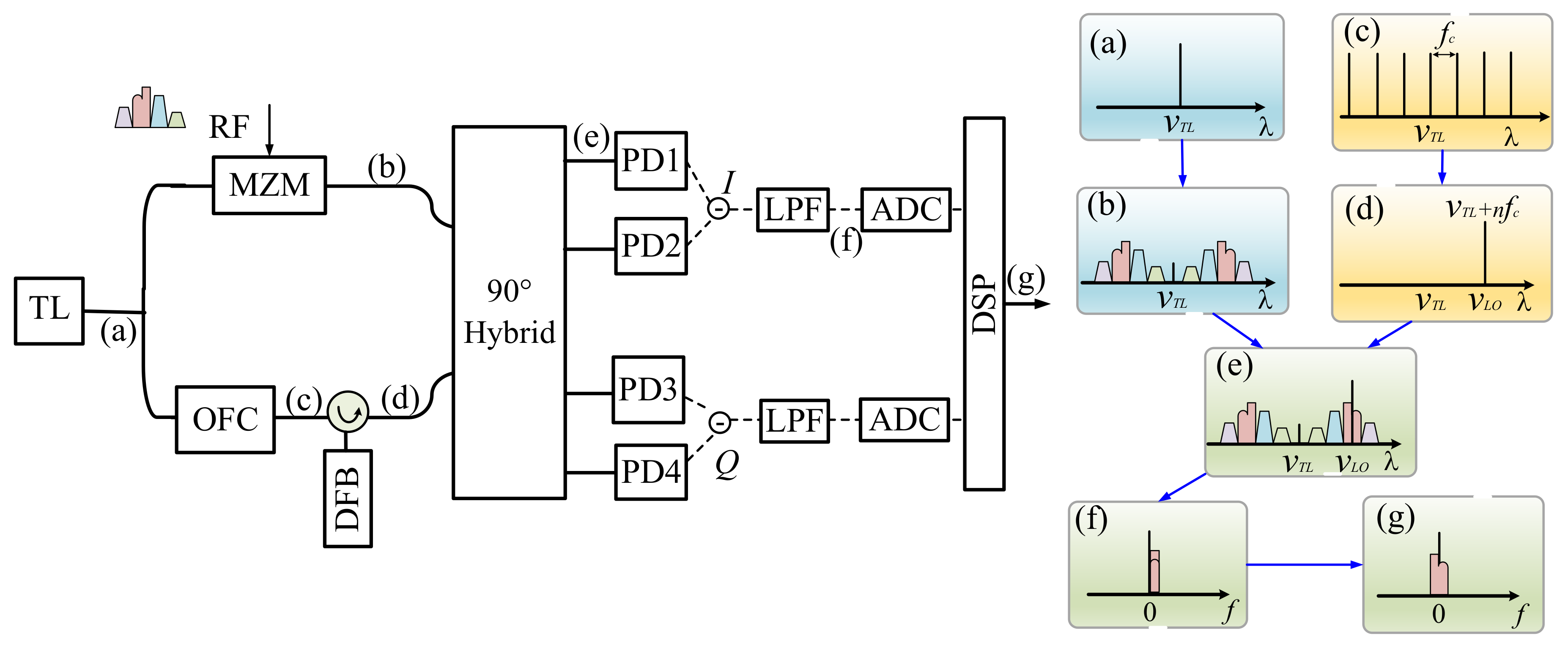
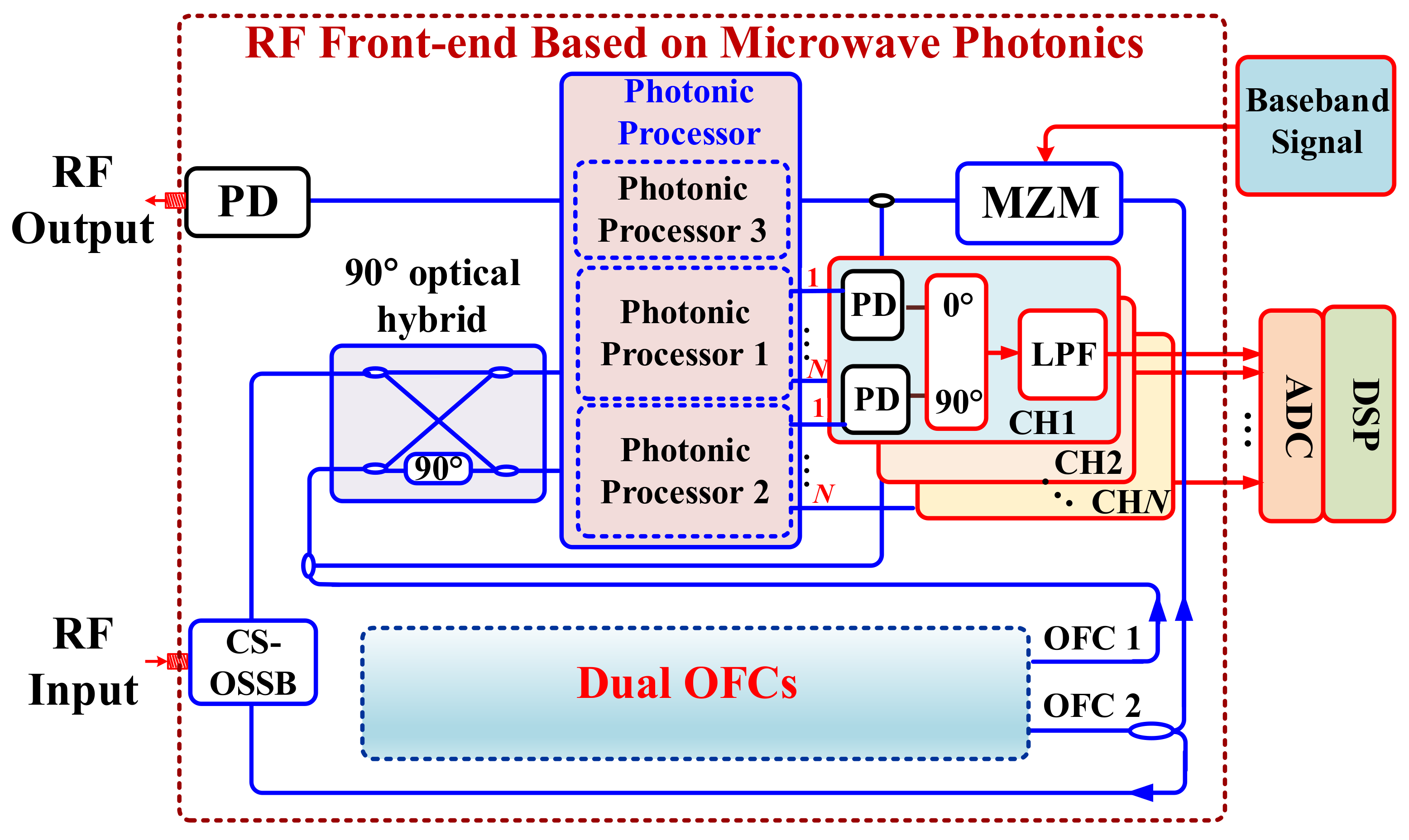
In addition, broadband flexible reconfigurable RF front-ends can be built based on photonics-based microwave IRMs [35]. This is of great importance for future RF systems, such as multi-functional radars, broadband electronic warfare and intelligent satellites, to achieve multi-band RF signals for receiving and emitting [36,37,38]. Previously, we have proposed and demonstrated a photonics-based RF front-end using photonics-based microwave IRMs [35], which can realize photonic multi-frequency LO generation, RF channelization, and multi-band up-conversion. Figure 10 shows a schematic diagram of a microwave photonic RF front-end. Dual OFCs with different free spectral ranges (FSRs) are generated and serve as photonic multi-frequency LOs. For signal receiving, the signal OFC is used as an optical carrier, which is modulated by the received RF signals with a CS-OSSB modulation format. The modulated OFC signal and the LO OFC are directed to a signal port and an LO port of a 90° optical hybrid, respectively. With a programmable multi-channel filter to select the desired signal, and with splitting of LO pairs into multiple channels, simultaneous image-reject down-conversion and channelization are implemented with the help of PDs and low-frequency electrical 90° hybrids. For signal transmitting, a signal OFC is injected into a Mach-Zehnder modulator (MZM) to modulate electrical baseband signals. Then, the modulated signal is combined with LO OFC and injected into a programmable multi-channel filter where desired optical components are selected. With a PD to perform optical heterodyne, frequency up-conversion to the required RF band is realized. A conceptual microwave photonic RF front-end covering S, X, K, Ku and Ka bands is successfully implemented. Simultaneous channelization, with downconversion for signal receiving, and frequency up-conversion for signal emitting, is demonstrated. Furthermore, based on this scheme, demonstration of a multi-channel microwave photonic satellite repeater has been established.
Another application of photonics-based microwave IRM is a wideband or multi-band radar system [39]. Generally, the key challenge associated with realization of multi-band radar systems is bandwidth limitation of the electronic components. Microwave photonics provide a promising solution due to the advantages brought by photonics, including higher carrier frequency and large bandwidth spectrum and so on [40,41,42]. Previously, a dual-band linear frequency-modulated continuous wave (LFMCW) radar receiver was built based on a photonic IRM [28]. Integrated up- and down-chirp linear frequency-modulated (LFM) waveforms located in two different bands were used as transmitted signals. Without photonics-based microwave IRM, the image component of beat frequency from the up- and down-chirp bands would overlap with each other, resulting in false targets. A photonic IRM scheme offers the possibility of independent target detection, and allows the sharing of hardware resources and joint dechirp processing of dual bands. The image components can be further suppressed using subsequent digital I/Q imbalance compensation. In addition to the above microwave applications, an all-fiber continuous-wave coherent Doppler LiDAR was reported, based on photonic IRMs [43].
5. Discussions and Conclusions
In conclusion, we reviewed recent advances in photonics-based microwave IRMs. Two typical methods to realize the photonic IRM, i.e., pre-filtering method and phase cancellation method, were introduced. Application of the photonics-based microwave IRM in electronic warfare, radar and satellite systems, was also described.
Currently, photonics-based microwave IRMs are mainly realized using discrete components, so their performance will be affected by environmental vibration, leading to serious problems for practical applications [46]. For example, the lengths of the two paths constructed by discrete components are difficult to keep stable, introducing amplitude and/or phase variation of the signals transmitted through them. To realize compact photonics-based microwave IRMs with high stability, integrated microwave photonic technology can be applied [47,48,49,50,51,52,53,54,55,56,57,58,59,60]. Integrated components including modulators, 90° optical hybrids, PDs [47,48,49], optical oscillators and circulators [50], integrated sub-systems (such as lasers) [51], microwave photonic spectrum shapers [52], phase shifters [53], delay lines [54], filters [55] and processors [56,57,58,59] have been widely investigated, and great progress has been made. In addition, incorporation of new materials, such as graphene [60], to the field of integrated microwave photonics, brings new advantages, such as fast tuning speed, high nonlinearity and so on. Therefore, integrating photonics-based microwave IRM in a chip is possible, which is expected to achieve better performance for practical applications.
Acknowledgments
This work is supported by the Natural Science Foundation of Jiangsu Province (BK20160082), the Jiangsu Provincial Program for High-level Talents in Six Areas (DZXX-030), and the Fundamental Research Funds for Central Universities.
Author Contributions
This article was jointly written by and proof-read by all authors. All authors contributed in various degrees to the review.
Conflicts of Interest
The authors declare no conflict of interest.
References
- Ghelfi, P.; Laghezza, F.; Scotti, F.; Serafino, G.; Capria, A.; Pinna, S.; Onori, D.; Porzi, C.; Scaffardi, M.; Malacarne, A. A fully photonics-based coherent radar system. Nature 2014, 507, 341–345. [Google Scholar] [CrossRef] [PubMed] [Green Version]
- Pan, S.L.; Zhu, D.; Liu, S.F.; Xu, K.; Dai, Y.T.; Wang, T.L.; Liu, J.G.; Zhu, N.H.; Xue, Y.; Liu, N.J. Satellite payloads pay off. IEEE Microw. Mag. 2015, 16, 61–73. [Google Scholar] [CrossRef]
- Ghelfi, P.; Onori, D.; Laghezza, F.; Scotti, F.; Bogoni, A.; Albertoni, A.; Tafuto, A. An RF scanning receiver based on photonics for electronic warfare applications. In Proceedings of the 12th European Radar Conference, Paris, France, 9–11 September 2015; pp. 197–200. [Google Scholar]
- Laghezza, F.; Scotti, F.; Ghelfi, P.; Bogoni, A. Photonics-assisted multiband RF transceiver for wireless communications. J. Lightwave Technol. 2014, 32, 2896–2904. [Google Scholar] [CrossRef]
- Capmany, J.; Novak, D. Microwave photonics combines two worlds. Nat. Photonics 2007, 1, 319–330. [Google Scholar] [CrossRef]
- Yao, J.P. Microwave photonics. J. Lightwave Technol. 2009, 27, 314–335. [Google Scholar] [CrossRef]
- Chan, E.H.W.; Minasian, R.A. Microwave photonic downconverter with high conversion efficiency. J. Lightwave Technol. 2012, 30, 3580–3585. [Google Scholar] [CrossRef]
- Li, P.; Pan, W.; Zou, X.; Lu, B.; Yan, L.; Luo, B. Image-free microwave photonic down-conversion approach for fiber-optic antenna remoting. IEEE J. Quantum Electron. 2017, 53, 9100208. [Google Scholar] [CrossRef]
- Zhu, D.; Liu, S.F.; Pan, S.L. Multi-channel up-conversion based on polarization-modulated optoelectronic oscillator. IEEE Photonics Technol. Lett. 2014, 26, 544–547. [Google Scholar] [CrossRef]
- Cook, J.A.; Henderson, B.C. Image Reject and SSB Mixers; Tech-Note; Watkins-Jonson Co.: Palo Alto, CA, USA, 1985. [Google Scholar]
- IRM (14.0–18.0) GHz. Available online: https://polyphasemicrowave.com/product/image-reject-mixer-14-18-frequency-ghz/ (accessed on 2 February 2017).
- Lindsay, A.C.; Knight, G.A.; Winnall, S.T. Photonic mixers for wide bandwidth RF receiver applications. IEEE Trans. Microw. Theory Tech. 1995, 43, 2311–2317. [Google Scholar] [CrossRef]
- Strutz, S.J.; Williams, K.J. An 8–18-GHz all-optical microwave downconverter with channelization. IEEE Trans. Microw. Theory Tech. 2001, 49, 1992–1995. [Google Scholar] [CrossRef]
- Strutz, S.J.; Williams, K.J. A 0.8–8.8-GHz image rejection microwave photonic downconverter. IEEE Photonics Technol. Lett. 2000, 12, 1376–1378. [Google Scholar] [CrossRef]
- Strutz, S.J.; Biernacki, P.; Nichols, L.; Williams, K.J. Demonstration of a wide-band image rejection microwave downconverter. IEEE Photonics Technol. Lett. 2000, 12, 687–689. [Google Scholar] [CrossRef]
- Strutz, S.J.; Williams, K.J. A 6 to 11 GHz all-optical image rejection microwave downconverter. In Proceedings of the International Topical Meeting on Microwave Photonics, Oxford, UK, 11–13 September 2000; pp. 74–77. [Google Scholar]
- Ward, A.; Nichols, L.T.; Biernacki, P.D.; Williams, K.J. An ultrawideband image rejecting microwave downconverter using WDM. In Proceedings of the International Topical Meeting on Microwave Photonics, Melbourne, Australia, 17–19 November 1999; pp. 239–242. [Google Scholar]
- Lu, C.; Chen, W.; Shiang, J.F. Photonic mixers and image-rejection mixers for optical SCM systems. IEEE Trans. Microw. Theory Tech. 1997, 45, 1478–1480. [Google Scholar] [CrossRef]
- Ogawa, H.; Kamitsuna, H. Fiber optic microwave links using balanced laser harmonic generation, and balanced/image cancellation laser mixing. IEEE Trans. Microw. Theory Tech. 1992, 40, 2278–2284. [Google Scholar] [CrossRef]
- Zhang, J.; Chan, E.H.W.; Wang, X.; Feng, X.; Guan, B. High conversion efficiency photonic microwave mixer with image rejection capability. IEEE Photonics J. 2016, 8, 1–11. [Google Scholar] [CrossRef]
- Tang, Z.Z.; Pan, S.L. Image-reject mixer with large suppression of mixing spurs based on a photonic microwave phase shifter. J. Lightwave Technol. 2016, 34, 4729–4735. [Google Scholar] [CrossRef]
- Gao, Y.; Wen, A.; Chen, W.; Li, X. All-optical, ultra-wideband microwave I/Q mixer and image-reject frequency down-converter. Opt. Lett. 2017, 42, 1105–1108. [Google Scholar] [CrossRef] [PubMed]
- Gao, Y.; Wen, A.; Zhang, W.; Jiang, W.; Ge, J.; Fan, Y. Ultra-wideband photonic microwave I/Q mixer for zero-IF receiver. IEEE Trans. Microw. Theory Tech. 2017, 65, 4513–4525. [Google Scholar] [CrossRef]
- Zhang, W.; Wen, A.; Gao, Y.; Shang, S.; Zheng, H.; He, H. Large bandwidth photonic microwave image rejection mixer with high conversion efficiency. IEEE Photonics J. 2017, 9, 7201908. [Google Scholar] [CrossRef]
- Tang, Z.Z.; Pan, S.L. A Reconfigurable photonic microwave mixer using a 90° optical hybrid. IEEE Trans. Microw. Theory Tech. 2016, 64, 3017–3025. [Google Scholar] [CrossRef]
- Tang, Z.Z.; Pan, S.L. Reconfigurable microwave photonic mixer with minimized path separation and large suppression of mixing spurs. Opt. Lett. 2017, 42, 33–36. [Google Scholar] [CrossRef] [PubMed]
- Pan, S.L.; Tang, Z.Z. A highly reconfigurable photonic microwave frequency mixer. SPIE Newsroom 2015. [Google Scholar] [CrossRef]
- Meng, Z.; Li, J.; Yin, C.; Fan, Y.; Yin, F.; Zhou, Y.; Dai, Y.; Xu, K. Dual-band dechirping LFMCW radar receiver with high image rejection using microwave photonic I/Q mixer. Opt. Express 2017, 25, 22055–22065. [Google Scholar] [CrossRef] [PubMed]
- Li, J.; Xiao, J.; Song, X.; Zheng, Y.; Yin, C.; Lv, Q.; Fan, Y.; Yin, F.; Dai, Y.; Xu, K. Full-band direct-conversion receiver with enhanced port isolation and I/Q phase balance using microwave photonic I/Q mixer. Chin. Opt. Lett. 2017, 15, 66–69. [Google Scholar] [CrossRef]
- Chen, W.J.; Zhu, D.; Pan, S.L. Multi-octave image-reject mixer with large suppression of mixing spurs based on balanced photodetectors. CLEO 2018. submitted. [Google Scholar]
- Tang, Z.Z.; Zhu, D.; Pan, S.L. Coherent RF channelizer based on dual optical frequency combs and image-reject mixers. In Proceedings of the 2017 International Topical Meeting on Microwave Photonics (MWP 2017), Beijing, China, 23–26 October 2017. [Google Scholar]
- Tang, Z.Z.; Zhu, D.; Pan, S.L. A Coherent Optical RF Channelizer with Large Instantaneous Bandwidth and Large in-band Interference Suppression. J. Lightwave Technol. 2018. accepted. [Google Scholar]
- Onori, D.; Scotti, F.; Laghezza, F.; Bogoni, A.; Ghelfi, P.; Bartocci, M.; Zaccaron, A.; Tafuto, A.; Albertoni, A. Relavant field trial of a photonics-based RF scanning receiver for electronic support measures. In Proceedings of the IEEE International Topical Meeting on Microwave Photonics, Long Beach, CA, USA, 31 October–3 November 2016; pp. 65–68. [Google Scholar]
- Onori, D.; Laghezza, F.; Scotti, F.; Bogoni, A.; Ghelfi, P.; Bartocci, M.; Zaccaron, A.; Tafuto, A.; Albertoni, A. A DC offset-free ultra-wideband direct conversion receiver based on photonics. In Proceedings of the 13th European Radar Conference, London, UK, 5–7 October 2016; pp. 374–377. [Google Scholar]
- Zhu, D.; Chen, W.J.; Chen, Z.W.; Du, T.H.; Tang, Z.Z.; Pan, S.L. RF front-end based on microwave photonics. In Proceedings of the 2017 Opto-Electronics and Communications Conference (OECC) and Photonics Global Conference (PGC), Singapore, 31 July–4 August 2017. [Google Scholar]
- Wang, J.; Chen, M.; Liang, Y.; Chen, H.; Yang, S.; Xie, S. Broadband RF front-end using microwave photonics filter. Opt. Express 2015, 23, 839–845. [Google Scholar] [CrossRef] [PubMed]
- Yu, H.; Yu, H.; Wang, J.; Chen, M.; Hoekman, M.; Chen, H.; Leinse, A.; Heideman, R.G.; Mateman, R.; Yang, S.; et al. Photonic-assisted RF frontend operating at U-band and V-band based on Si3N4 ultra-high-Q bandpass filter. In Proceedings of the Optical Fiber Communications Conference and Exhibition 2016 (OFC 2016), Anaheim, CA, USA, 20–24 March 2016. [Google Scholar]
- Clark, T.R.; Waterhouse, R. Photonics for RF front ends. IEEE Microw. Mag. 2011, 12, 87–95. [Google Scholar] [CrossRef]
- Casey, J.A.; Howell, S.E.L.; Tivy, A.; Haas, C. Separability of sea ice types from wide swath C-and L-band synthetic aperture radar imagery acquired during the melt season. Remote Sens. Environ. 2016, 174, 321–328. [Google Scholar] [CrossRef]
- Ghelfi, P.; Laghezza, F.; Scotti, F.; Serafino, G.; Pinna, S.; Onori, D.; Lazzeri, E.; Bogoni, A. Photonics in radar systems: RF integration for state of-the-art functionality. IEEE Microw. Mag. 2015, 16, 74–83. [Google Scholar] [CrossRef]
- Ghelfi, P.; Laghezza, F.; Scotti, F.; Onori, D.; Bogoni, A. Photonics for radars operating on multiple coherent bands. J. Lightwave Technol. 2015, 34, 500–507. [Google Scholar] [CrossRef]
- Emami, H.; Sarkhosh, N. Reconfigurable microwave photonic in-phase and quadrature detector for frequency agile radar. J. Opt. Soc. Am. A 2014, 31, 1320–1325. [Google Scholar] [CrossRef] [PubMed]
- Abari, C.F.; Pedersen, A.T.; Dellwik, E.; Mann, J. Performance evaluation of an all-fiber image-reject homodyne coherent Doppler wind lidar. Atmos. Meas. Tech. 2015, 8, 3729–3752. [Google Scholar] [CrossRef]
- Capmany, J.; Ortega, B.; Pastor, D. A tutorial on microwave photonic filters. J. Lightwave Technol. 2006, 24, 201–229. [Google Scholar] [CrossRef]
- Ortega, B.; Min, R.; Sáez-Rodríguez, D.; Mi, Y.; Nielsen, K.; Bang, O. Bandpass transmission filters based on phase shifted fiber Bragg gratings in microstructured polymer optical fibers. Proc. SPIE 2017, 10232, 1023209. [Google Scholar] [CrossRef]
- Yu, H.; Chen, M.; Guo, Q.; Hoekman, M.; Chen, H.; Leinse, A.; Heideman, R.G.; Mateman, R.; Yang, S.; Xie, S. All-optical full-band RF receiver based on an integrated ultra-high-Q bandpass filter. J. Lightwave Technol. 2016, 34, 701–706. [Google Scholar] [CrossRef]
- Yi, X.; Chew, S.X.; Song, S.; Nguyen, L.; Minasian, R. Integrated microwave photonics for wideband signal processing. Photonics 2017, 4, 46. [Google Scholar] [CrossRef]
- Chen, M.; Yu, H.; Wang, J. Silicon photonics-based signal processing for microwave photonic frontends. In Silicon Photonics III; Topics in Applied Physics; Pavesi, L., Lockwood, D., Eds.; Springer: Berlin/Heidelberg, Germany, 2016. [Google Scholar] [CrossRef]
- Marpaung, D.; Roeloffzen, C.; Heideman, R.; Leinse, A.; Sales, S.; Capmany, J. Integrated microwave photonics. Laser Photonics Rev. 2013, 7, 506–538. [Google Scholar] [CrossRef]
- Pintus, P.; Huang, D.; Zhang, C.; Shoji, Y.; Mizumoto, T.; Bowers, J.E. Microring-based Optical Isolator and Circulator with Integrated Electromagnet for Silicon Photonics. J. Lightwave Technol. 2017, 35, 1429–1437. [Google Scholar] [CrossRef]
- Liu, W.; Li, M.; Guzzon, R.S.; Norberg, E.J.; Parker, J.S.; Lu, M.; Coldren, L.A.; Yao, J.P. A photonic integrated parity-time symmetry wavelength-tunable single-mode microring laser. Nat. Commun. 2017, 10, 190–196. [Google Scholar] [CrossRef]
- Khan, M.H.; Shen, H.; Xuan, Y.; Zhao, L.; Xiao, S.; Leaird, D.E.; Weiner, A.M.; Qi, M. Ultrabroad-bandwidth arbitrary radiofrequency waveform generation with a silicon photonic chip-based spectral shaper. Nat. Photonics 2010, 4, 117–122. [Google Scholar] [CrossRef]
- Urick, V.J.; Mondich, M.J.; Sunderman, C.E.; Kozak, D.A.; Goetz, P.G.; Rabinovich, W.S.; Pruessner, M.W.; Mahon, R.; Williams, K.J. Microwave Phase Shifting Using Coherent Photonic Integrated Circuits. IEEE J. Sel. Top. Quantum Electron. 2016, 22, 6100408. [Google Scholar] [CrossRef]
- Liu, Y.; Choudhary, A.; Marpaung, D.; Eggleton, B.J. Gigahertz optical tuning of an on-chip radio frequency photonic delay line. Optica 2017, 4, 418–423. [Google Scholar] [CrossRef]
- Fandiño, J.S.; Muñoz, P.; Doménech, D.; Capmany, J. A monolithic integrated photonic microwave filter. Nat. Photonics 2016, 11, 124–129. [Google Scholar] [CrossRef]
- Zhang, C.; Zhang, S.; Peters, J.D.; Bowers, J.E. 8 × 8 × 40 Gbps fully integrated silicon photonic network on chip. Optica 2016, 3, 785–786. [Google Scholar] [CrossRef]
- Dai, D.; Bowers, J.E. Silicon-based on-chip multiplexing technologies and devices for Peta-bit optical interconnects. Nanophotonics 2014, 3, 283–311. [Google Scholar] [CrossRef]
- Liu, W.; Li, M.; Guzzon, R.S.; Norberg, E.J.; Parker, J.S.; Lu, M.; Coldren, L.A.; Yao, J.P. A fully reconfigurable photonic integrated signal processor. Nat. Photonics 2016, 10, 190–195. [Google Scholar] [CrossRef]
- Xue, X.; Leo, F.; Xuan, Y.; Jaramillo-Villegas, J.A.; Wang, P.-H.; Leaird, D.E.; Erkintalo, M.; Qi, M.; Weiner, A.M. Second-harmonic-assisted four-wave mixing in chip-based microresonator frequency comb generation. Light Sci. Appl. 2017, 6, e16253. [Google Scholar] [CrossRef]
- Capmany, J.; Doménech, D.; Muñoz, P. Graphene Integrated Microwave Photonics. J. Lightwave Technol. 2014, 32, 3785–3796. [Google Scholar] [CrossRef]
Figure 1.
Schematic diagram illustrating image interference.

Figure 2.
Schematic diagram of photonic image-reject mixers (IRMs) based on direct pre-filtering in an (a) electrical and (b) optical domain; (c) pre-filtering principle of IRMs. EBPF: electrical bandpass filter; OBPF: optical bandpass filter; EO: electrical to optical conversion; OE: optical to electrical conversion.
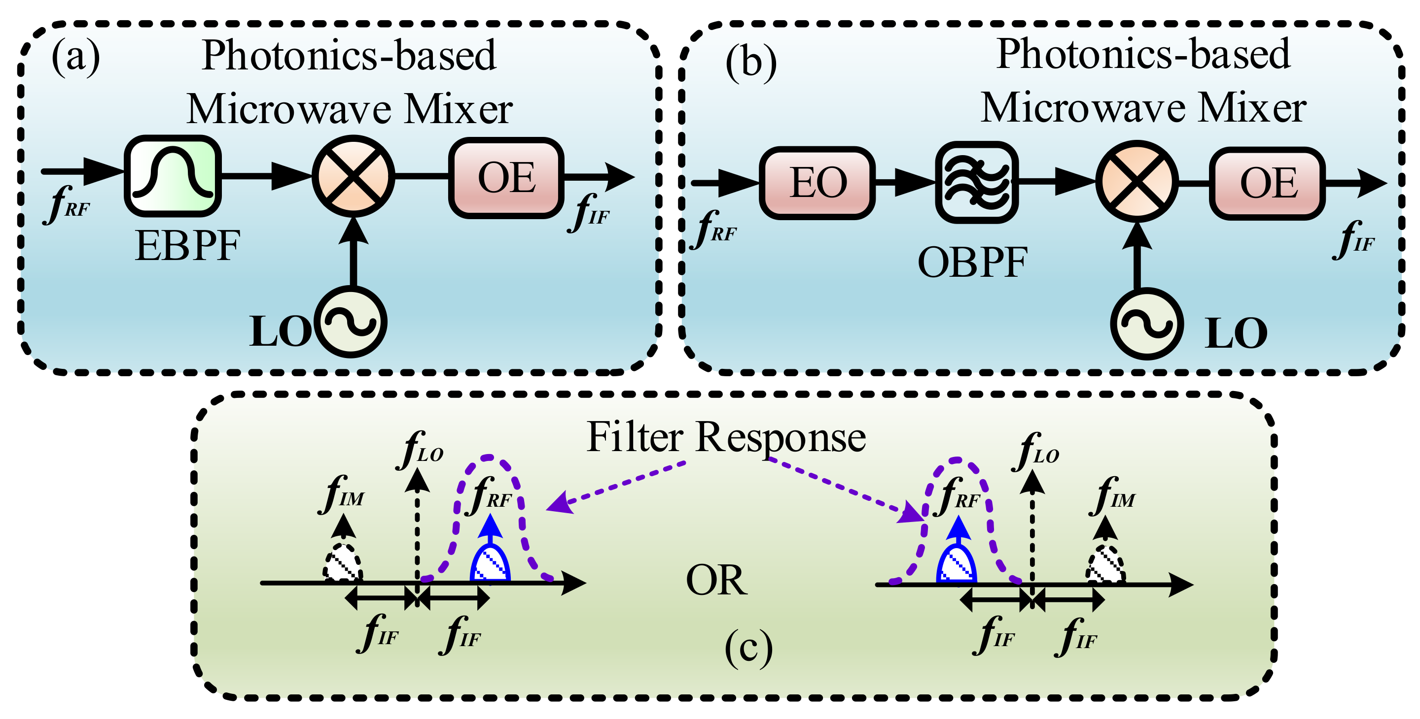
Figure 3.
Schematic diagram of photonic an IRM based on multiple-stage frequency conversion.
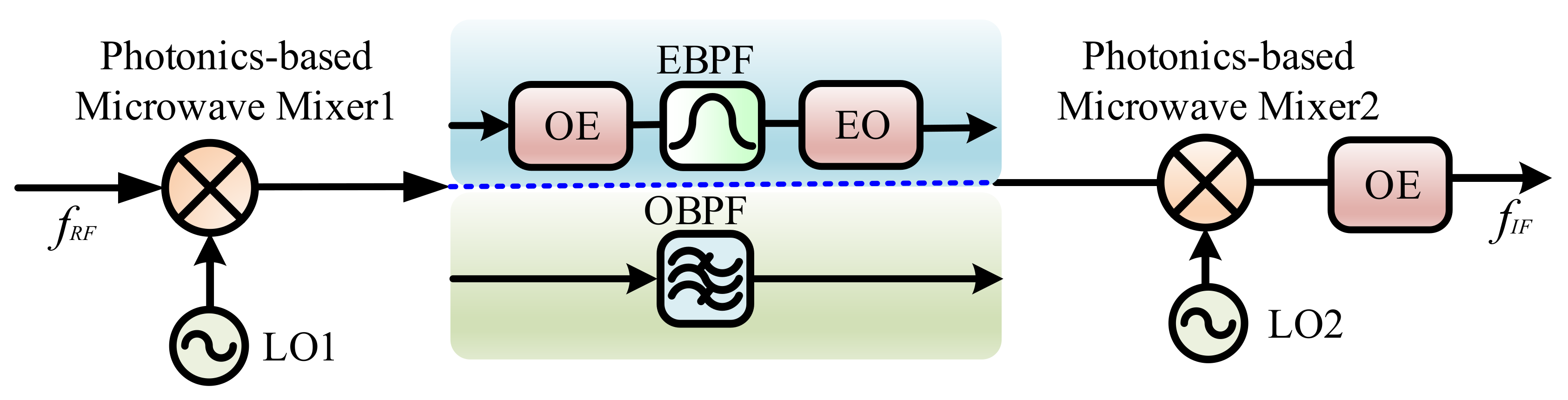
Figure 4.
Principle of a photonic IRM based on multiple-stage frequency conversion: (a) the received RF signal and the location of LO1; (b) the downconverted signal using LO1 and the image to be rejected by the bandpass filter (BPF); (c) the signal downconverted to the desired output intermediate frequency (IF) band using LO2.

Figure 5.
Schematic diagram of a photonic IRM, based on phase cancellation. IF: intermediate frequency.
Figure 5.
Schematic diagram of a photonic IRM, based on phase cancellation. IF: intermediate frequency.
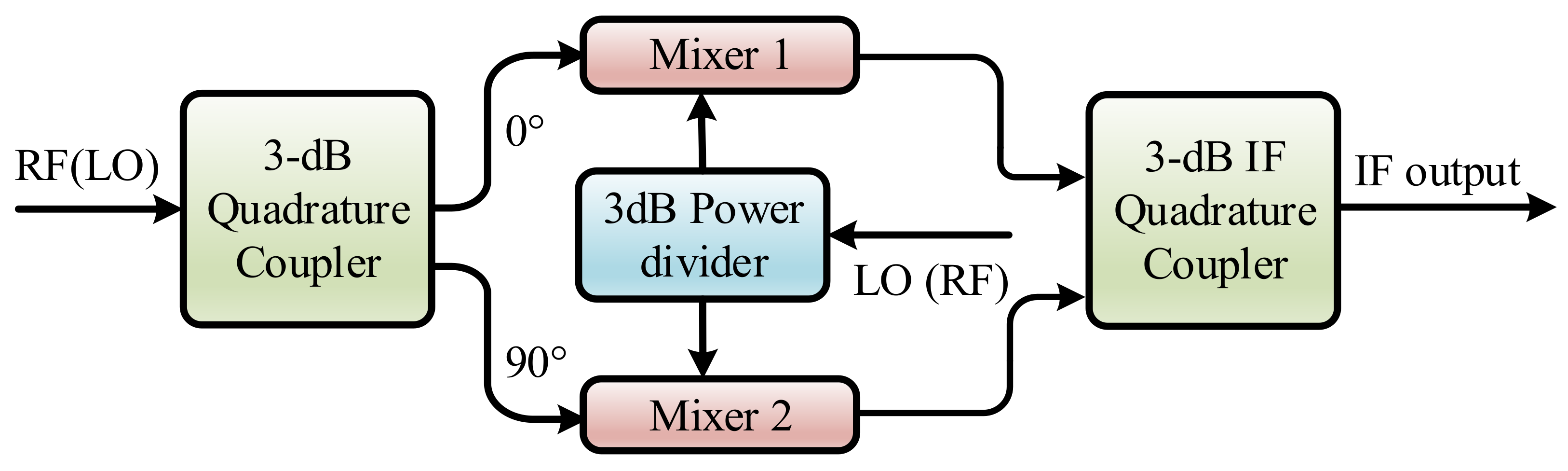
Figure 6.
A photonic IRM using an electrical 90° hybrid to generate quadrature RFs. LD: laser diode; PD: photodetector [19].
Figure 6.
A photonic IRM using an electrical 90° hybrid to generate quadrature RFs. LD: laser diode; PD: photodetector [19].

Figure 7.
Schematic diagram of a typical photonic IRM using a 90° optical hybrid [25].
Figure 7.
Schematic diagram of a typical photonic IRM using a 90° optical hybrid [25].
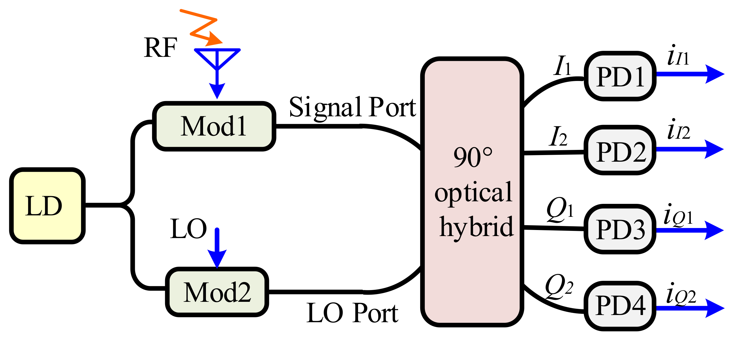
Figure 8.
(a1,b1) Electrical spectra and (a2,b2) time-frequency diagrams of the downconverted results for schemes in (a1,a2) [30] and (a1,b1) [25] when an RF signal with 2-GHz bandwidth and corresponding image are received simultaneously.
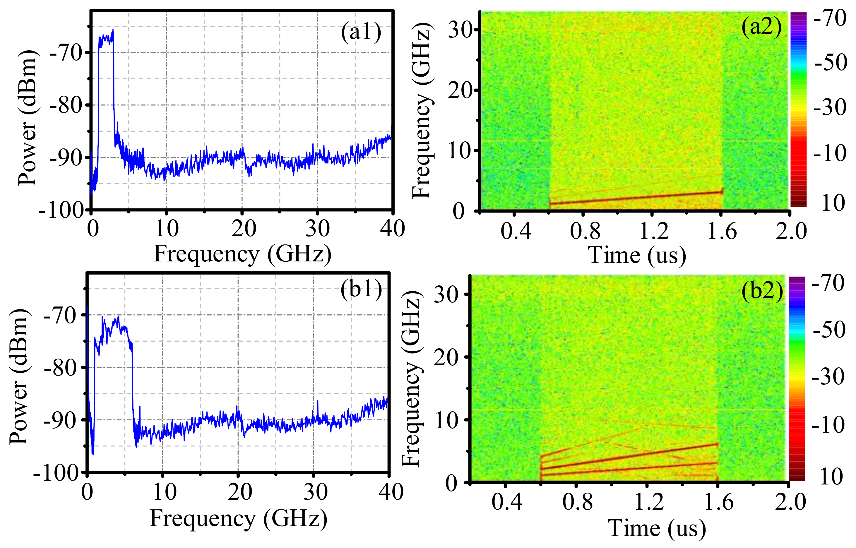
Figure 9.
Scheme of a photonics-assisted electronic warfare scanning receiver using a photonics-based microwave mixer incorporating a 90° optical hybrid [34].
Figure 9.
Scheme of a photonics-assisted electronic warfare scanning receiver using a photonics-based microwave mixer incorporating a 90° optical hybrid [34].

Figure 10.
Schematic diagram of the RF front-end based on microwave photonics. OFC: optical frequency comb; MZM: Mach-Zehnder modulator; LPF: low pass filter; ADC: analog to digital conversion [35].
Figure 10.
Schematic diagram of the RF front-end based on microwave photonics. OFC: optical frequency comb; MZM: Mach-Zehnder modulator; LPF: low pass filter; ADC: analog to digital conversion [35].

© 2018 by the authors. Licensee MDPI, Basel, Switzerland. This article is an open access article distributed under the terms and conditions of the Creative Commons Attribution (CC BY) license (http://creativecommons.org/licenses/by/4.0/).
Share and Cite
MDPI and ACS Style
Zhu, D.; Pan, S. Photonics-Based Microwave Image-Reject Mixer. Photonics 2018, 5, 6. https://doi.org/10.3390/photonics5020006
AMA Style
Zhu D, Pan S. Photonics-Based Microwave Image-Reject Mixer. Photonics. 2018; 5(2):6. https://doi.org/10.3390/photonics5020006
Chicago/Turabian StyleZhu, Dan, and Shilong Pan. 2018. "Photonics-Based Microwave Image-Reject Mixer" Photonics 5, no. 2: 6. https://doi.org/10.3390/photonics5020006
Note that from the first issue of 2016, this journal uses article numbers instead of page numbers. See further details here.