1. Introduction
Due to the rapid evolution of cloud services, traffic demand is growing dramatically every year in every network segment. Especially in core optical networks, this demand necessitates adaptation of high-speed channels in a power efficient and economically viable way. Transporting traffic at high bit rates, such as 100 Gbit/s, may become challenging as various impairments manifest themselves [
1]. Combating those impairments is cumbersome and power consuming, hence, the preferred solution choices are not obvious in network segments that are sensitive to cost and power consumption, like in metropolitan area networks [
2] and inter-data center networks [
3]. Typically, these segments are subject to unpredictable traffic changes and all distortions vary in a nondeterministic way.
Optical transport technologies optimized for such network applications with direct detection (DD) techniques gain an increasing number of supporters due to the adaptivity and low complexity offered by optical and electronic transmission technologies used to compensate for linear and nonlinear impairments [
4]. Chromatic dispersion (CD) is the prevailing linear impairment that causes intersymbol interference (ISI) [
2]. Distortion compensation techniques have been made readily available with optical and electronic means [
5,
6,
7]. Optical compensators are usually based on dispersion compensating fiber (DCF) placed along the optical transmission system, while electronic ones are usually based on equalizers. Optical compensating techniques are rigid as far as the amount of the CD they mitigate implying that its value is known in advance. Electronic equalizers [
5,
8], on the other hand, are utilized adjustably after signal detection and can additionally compensate part of the PMD [
6]. Equalization methods can be performed by a maximum likelihood sequence estimation (MLSE) method [
6] or on the use of non-linear decision feedback filters for mitigating ISI in optical communication systems. Equalization methods based on recursive Volterra nonlinear filters have been proposed [
7,
9], noting however, that the use of Volterra equalizers still becomes cumbersome when the ISI extends more than a few symbols.
In high data rate systems, signal distortions caused by intersymbol interference increase proportionally to the square of the data rate, hence, the performance of the transmission system is very sensitive to the possible residual dispersion at the receiver. Optical dispersion compensation can only compensate for specific values of chromatic dispersion, however, in dynamic multi-channel network segments dispersion is not always known in advance. As discussed in [
2] optical transmission systems can benefit from a combination of rigid DCF with adaptive equalization at the receiver where residual dispersion is adjustably compensated after signal detection.
In this paper, we investigate the performance of the conventional non-return to zero differential quaternary phase shift keying (NRZ-DQPSK) optical link that comprises an optical channel with standard single mode and dispersion compensating fiber and various receiver configurations that combine single-ended receivers and joint reduced complexity Volterra-type equalizers [
2,
10,
11]. For the first time, to our knowledge, the scope of the investigation takes advantage of the linear dependency among the electrical signals (constructive/destructive and in-phase/quadrature) at the receiver side, to further reduce the complexity of proposed equalizers, allowing for numerically sound and viable implementation configurations. The proposed partially-joint single-ended digital equalization schemes for the DQPSK signaling utilize a triplet out of the quartet of electrical signals (constructive/destructive and in-phase/quadrature) available at the single ended receiver, for equalization, and eventually the detection of the transmitted bit streams. As a result a 25% reduction of the computational cost compared to the fully-deployed joint counterpart is achieved. As the hardware implementation circuitry of a digital equalizer is proportional to the computational complexity and the memory requirements [
2,
10,
12], the proposed approach offers reduced cost solutions that can be viably applied for the equalization of high-speed, high-performance optical transmission systems. A comparative study of the performance of the proposed equalization schemes is performed by means of computer simulations, using a typical 40 Gb/s optical transmission setup.
2. DQPSK Equalization
DQPSK is a four-level modulation format initially introduced to overcome spectral efficiency limitations of direct detection binary modulation formats [
1]. Recently, DQPSK has been revisited together with other direct detection techniques for cost efficiency [
13] or nonlinearity mitigation [
14]. Today, processing the signal electronically at symbol rate speeds is very typical in coherent optical transponders, however, in applications restricted by cost, direct detection is revisited [
15,
16,
17] and DQPSK is a very important candidate [
2]. Let
and
represent the encoded transmitted sequences of the
I and
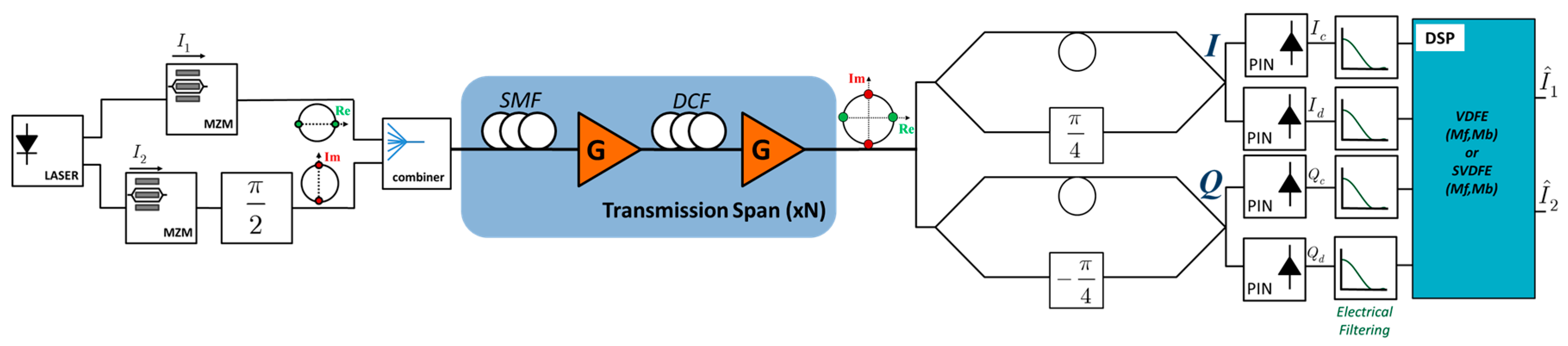
Q channels, which are encoded and modulated using a standard DQPSK transmitter setup (
Figure 1). A typical optical communication link consists of numerous identical fiber spans where part of the accumulated dispersion in the single mode fiber (SMF) is compensated by means of DCF and losses by optical amplifiers. At the receiver side, after optical bandpass filtering, the signal is demodulated by means of two separate Mach Zehnder delay interferometers (MZDI). Each arm of the MZDI has a phase shift of π/4 (in-phase component) and –π/4 (quadrature component). Subsequently, each output of the MZDI devices is detected by a photodiode and is filtered by an electrical low-pass filter (ELPF), producing in this way a set of constructive and destructive signals for the in-phase, as well as for the quadrature component, denoted here by
Ic(
t),
Id(
t),
Qc(
t), and
Qd(
t), respectively [
18]. Although any pair of the combination {
Ic(
t),
Id(
t)} × {
Qc(
t),
Qd(
t)} may be utilized for the detection of the transmitted sequences, a scheme based on the differential output
I(
t) =
Ic(
t) −
Id(
t) and
Q(
t) =
Qc(
t) −
Qd(
t), known as ‘balanced detection’, is usually used instead, offering in this case a 3 dB OSNR gain compared to the former approach.
Electronic equalization is usually applied for the suppression of either all, or a part (residual) of the distortions introduced by the fiber. In the case when the DQPSK receiver is implemented by means of balanced detection, the equalization methods are referred to as ‘balanced DQPSK equalization’. However, it has been demonstrated that the joint use of all the signals available at the receiver for equalization, provides improved results compared to those obtained if the differential output signals are used instead, for sequence, as well as for symbol-by-symbol equalization [
9,
19]. The latter approach is known as ‘joint DQPSK equalization’.
Symbol-by-symbol electronic equalization of direct detection optical transmission by means of recursive Volterra nonlinear filters has drawn significant attention in the past, for NRZ, DPSK, and DQPSK signaling. The feasibility of the implementation of those methods on FPGA (Field-Programmable Gate Array) circuitry has recently been demonstrated [
2,
12,
20], for rates up to 40 Gb/s. Due to the joint constructive/destructive processing, four signals are available as input to the equalizer. Further signal diversity is achieved by fractionally spaced sampling, as in this case the performance of the electronic equalizers becomes less sensitive to the sampling phase of the receiver [
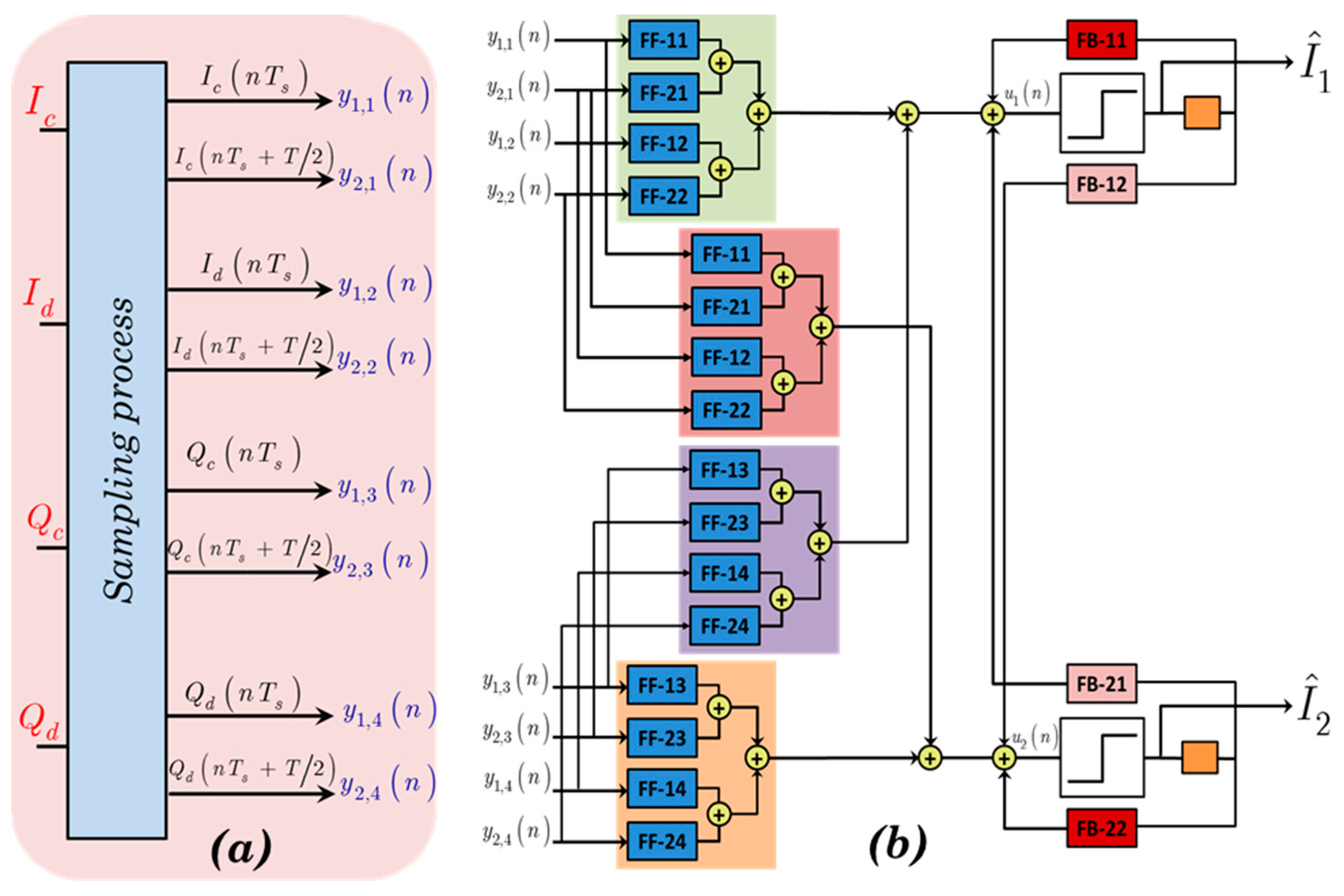
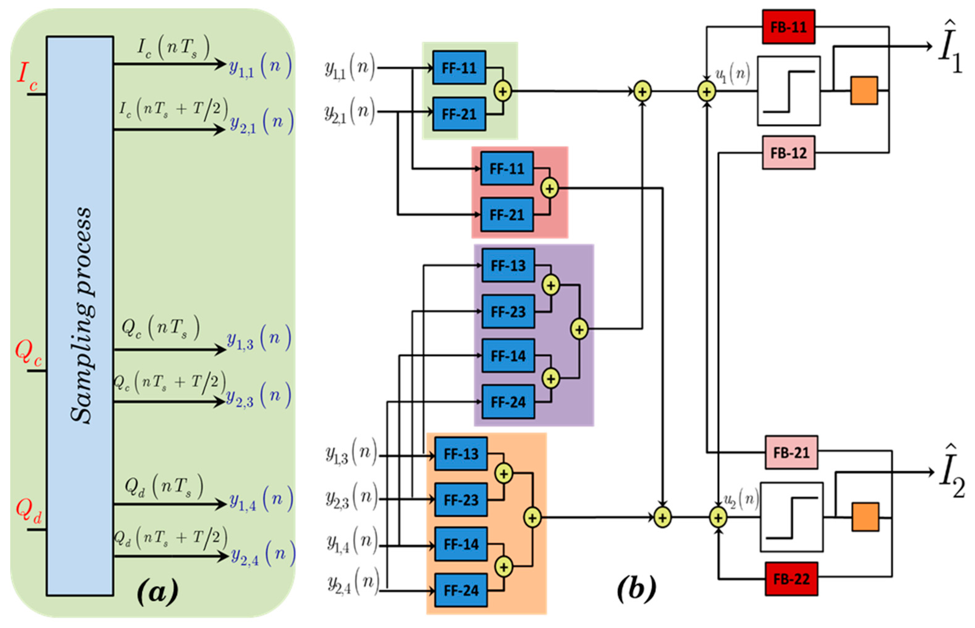
21]. We here adopt half rate spaced sampling,
, where
is the symbol period. Thus, after digital to analog conversion (D2A), eight signals (depicted on
Figure 2a) are eventually fed to the feed-forward part of the equalizer, namely:
Following [
19], a symbol-by-symbol, joint DQPSK Volterra decision feedback (VDFE) equalizer, is described as
):
where
and
are the output signals of equalizer for the in-phase and quadrature part, respectively. Parameters designated by symbol
f correspond to the feed-forward (FF) part of the equalizer which compensates for the precursor distortions. Parameters designated by symbol
b correspond to the feedback (FB) part of the equalizer which compensates for the post cursor distortions correspondingly. Integers
Mf and
Mb represent the memory of the FF and the FB part of the equalizer, respectively, and are both related to the amount of distortions that affect the transmission. Signals
and
represent the recovered in-phase and quadrature bit streams, with D denoting the decision device, as it is explained also in [
7,
9] and [
22]. Hence, the VDFE equalizer described by Equation (2), hereafter will be denoted as VDFE[
Mf,
Mb], and its structure is summarized in
Figure 2b.
The mathematical formulae that describes the VDFE can be expressed in a linear regression form as
,
where
is a vector that depends on the input signals and on the recovered bit streams,
represents the vectors that carries the equalizer coefficients for the in-phase and the quadrature part of the equalizer, with
T denoting the matrix transpose. Integer
M denotes the number of coefficients for each part of the equalizer. It provides a metric of complexity of the implementation of the recursive scheme, as the number of multiplications and additions required for the computation of
and
is
C = 2
M, in our case given by:
The equalizer coefficients
are estimated by minimizing a properly chosen cost function between the output signals and a desired response signal [
22]. The least squares (LS) estimator is perhaps the most popular design approach, where the parameters sought are estimated minimizing the sum of the squared error between the output of the equalizer and a set of N training data,
and
, in our case. The optimum parameter vectors
correspond to the solution of a linear system of equations, the so called ‘normal equations’, which is obtained either explicitly by means of a direct system solver, or implicitly engaging an iterative or a time recursive estimation scheme. In the case of time varying distortions, the estimated values may be updated either periodically or on a sample-by-sample basis, blindly working in a decision-directed mode.
A significant reduction in the computational complexity of the equalization devices in DQPSK signaling may be obtained by processing the differential signals using balanced detection at the receiver. The formulation of the pertinent equalization schemes follow the guideline described above for the case of joint constructive/destructive processing, noting however, that the signal diversity at the receiver is limited to half of that in the former case, as instead of eight, four signals are now available for digital processing, namely
,
,
,
. As a consequence, the complexity of the corresponding balanced DQPSK equalizers are reduced to about half of that required for the joint processing case, however, at the expense of a significant deterioration in the attained performance [
2,
21].
3. Proposed Partially-Joint Single-Ended DQPSK Equalization
Boosting the performance while keeping the cost low is a challenging task in the design of reliable optical links. Low-complexity balanced DQPSK equalization demonstrates poor performance compared to the joint single-ended alternatives [
2]. Motivated by former studies concerning the performance of the balanced receivers in DPSK and in DQPSK signaling [
19,
23,
24], we proposed the use of a low complexity, partially-joint single-ended equalization scheme, using a subset of the signals available at the receiver, described by one of the possible combinations (
Ic,
Qc,
Qd), (
Id,
Qc,
Qd), (
Ic,
Id,
Qc), and (
Ic,
Id,
Qd). Due to fractionally-spaced sampling, each triplet corresponds to six signals that are digitally processed by the pertinent equalizer. The proposed three-port partially-joint single-ended VDFE equalizers, hereafter denoted by the ignored port, e.g., VDFE[
Mf,
Mb]-
Ix or VDFE[
Mf,
Mb]-
Qx, offer approximately a 25% reduction in the required circuitry, compared to the full joint processing counterpart. As it will be demonstrated in
Section 4, the proposed approach offers a low complexity alternative for electronic equalization, without sacrificing much of the performance if any at all, compared to the fully deployed counterpart. In order to complete the investigation of partially joint equalizer counterparts, also two port partially joint single ended VDFE equalizers are compared to the balanced receiver VDFE equalizers. All of the aforementioned equalization/receiver-related configurations are depicted in
Figure 3.
Let us consider that the signals processed are given by the triplet (
Ic,
Qc,
Qd), i.e., the destructive port of
I channel has been ignored, hence, the six signals (depicted on
Figure 4a) fed to the feed-forward part of the equalizer are:
Now the three-port partially-joint single ended VDFE equalizers VDFE[
Mf,
Mb]-
Id (presented in
Figure 4b) is described as:
.
The three remaining cases are treated in a similar way. A metric of complexity of the implementation of the recursive scheme, is
C = 2
M, given by:
Despite its high efficiency in combating the introduced distortion, VDFE in DQPSK exhibits quadratic computational complexity with respect to the ISI size. The increased hardware requirements raise a barrier in the deployment of such device in low-cost, high-speed optical links. To alleviate the complexity issues inherently introduced in the VDFE, reduced complexity counterparts has recently been introduced [
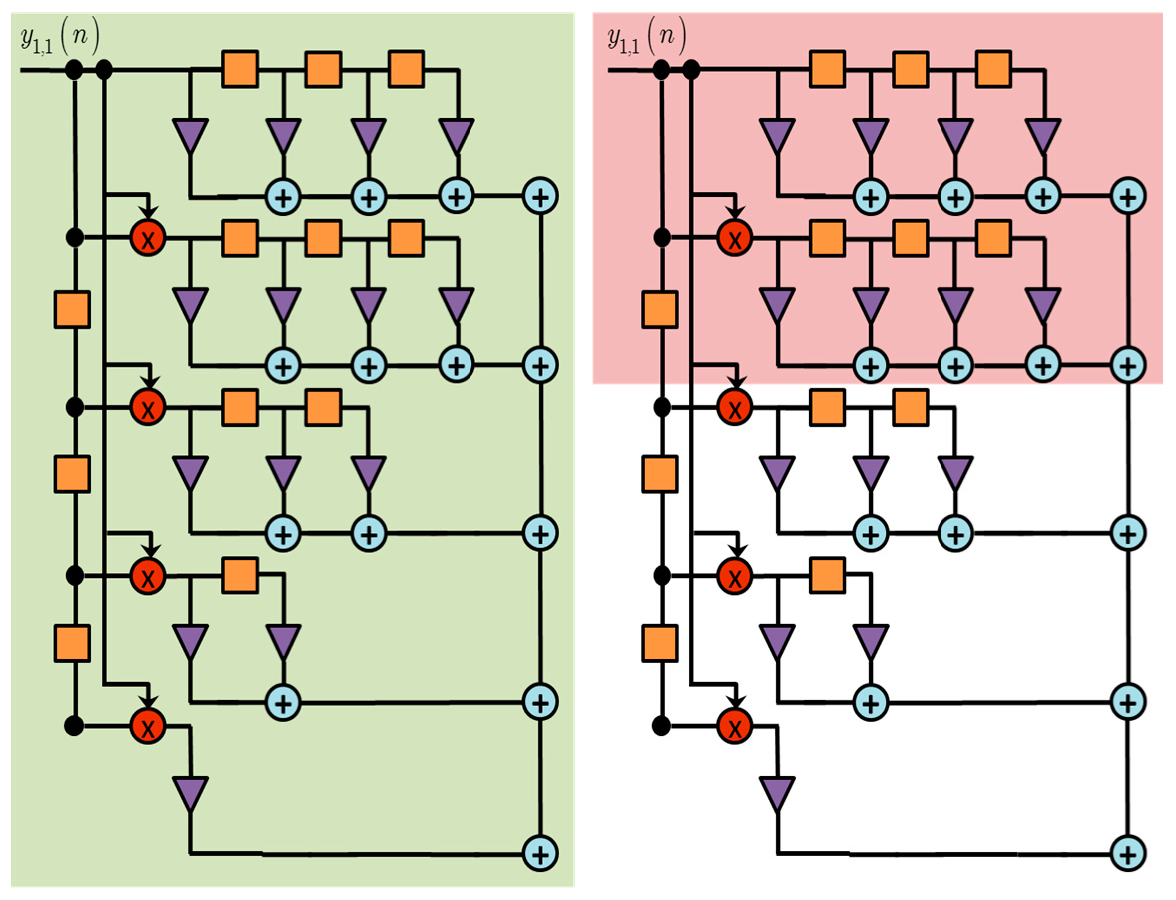
11], resorting to pruning techniques for the reduction of the size of the pertinent Volterra kernels, suppressing that part of the Volterra kernel that has a marginal contribution in the overall performance. The resulting pruned VDFE (PVDFE) equalizers, compared to the full-term design, is more tractable from an implementation point of view, leading to significant computational complexity savings, without sacrificing much of the performance compared to the fully-deployed counterpart.
A low complexity alternative of proposed three port partially joint single ended VDFE, is a degenerated form of PVDFE, the so called skimmed VDFE (SVDFE) [
10], where extreme pruning is applied to the feed-forward Volterra kernels, keeping only the coefficients that correspond to the diagonal of the full sized counterpart. VDFE employing skimmed Volterra kernels in place of the full-sized counterparts, have been proposed as a viable solution in high-speed, low-cost implementation for the equalization of OOK keying signaling, as well as for the DQPSK modulation, operating at bit rates as high as 40 Gb/s [
2,
10,
12,
20]. Assuming the same example of Equation (4), let the signals processed given by the triplet (
Ic,
Qc,
Qd), i.e., the destructive port of the I channel, be ignored. Now the three-port partially-joint single-ended SVDFE equalizers VDFE[
Mf,
Mb]-
Id is described as
).
The cases of all three-port partially-joint single-ended skimmed VDFE equalizer, (SVDFE[
Mf,
Mb]-
Ix or SVDFE[
Mf,
Mb]-
Qx) are treated similarly. In
Figure 5 the differences in structure of the feed-forward part between VDFE (
Figure 5a) and SVDFE (
Figure 5b) are depicted. While, in this particular block diagram the pruning procedure is presented only for one of the received signals it should be noted that the same technique implies for every different input signal.
The computational complexity for the estimation of
and
is now reduced to:
Compared to the complexity requirements of the fully-deployed counterpart (Equation (2)), a significant reduction is achieved, as in the latter case the computational requirement depends linearly on Mf, noting that the contribution of the last term in the summation is rather marginal as and represent binary digits.
Apart from the complexity reduction, the proposed partially-joint constructive/destructive equalization scheme offers better numerical behavior compared to the full counterpart. The use of all four signals
Ic(
t),
Id(
t),
Qc(
t), and
Qd(
t), available at the DQPSK receiver, improves performance by maximizing the signal diversity. MLSE equalizers certainly benefit from this approach, however, in the case of symbol by symbol equalizers, such as DFE and VDFE, some extra attention is required. Following the low-pass equivalent description of a DQPSK link [
24], we notice that in the case of ideal identical noise free photodetectors, the four electrical signals available at the receiver,
Ic(
t),
Id(
t),
Qc(
t), and
Qd(
t) are linearly dependent, as it can be easily shown that
Ic(
t) +
Id(
t) −
Qc(
t) −
Qd(
t) = 0. In a realistic situation, the presence of noise at the receiver results in (marginally) linear independence, as
Ic(
t) +
Id(
t) −
Qc(
t) −
Qd(
t) =
n(
t), with
n(
t) denoting the contribution of the noise signals from all four photodiodes. Noting that the coefficients of the VDFE equalizer (Equation (2)) are estimated by the solution of a linear system of equations either implicitly or explicitly, the condition number of the associated matrix which is formulated using the available signals (Equations (1)), is of crucial importance concerning the numerical accuracy of the estimated output [
22]. In the undesired situation when
n(
t) is much weaker than the remaining signals, the numerical behavior of the algorithm utilized for the estimation of the equalizer parameters (also known as the linear system solver) will deteriorate, resulting in severe ill-conditioning. A remedy to this problem is to resort to the use of proper regularization, such as the diagonal loading method, requiring extra effort for the handling of this overhead. On the contrary, the proposed partially-joint VDFE and its derivatives, do not suffer from such an effect, as three out of four electrical signals
Ic(
t),
Id(
t),
Qc(
t), and
Qd(
t), are engaged only. Simulation results indicated that the calculated condition number of the matrices involved into the estimation of the parameters of the equalizers (linear system of equations), vary from 10
6 up to 10
10 in the case of fully-joint constructive/destructive equalization. This figure is reduced to 10
3 in the case of partially-joint equalization.
4. Optical Layer Simulation
As shown in previous work [
2,
12,
20,
25] the amount of dispersion that an equalizer can compensate is directly related to both the memory of the FF
and FB
filters. As the values of
and
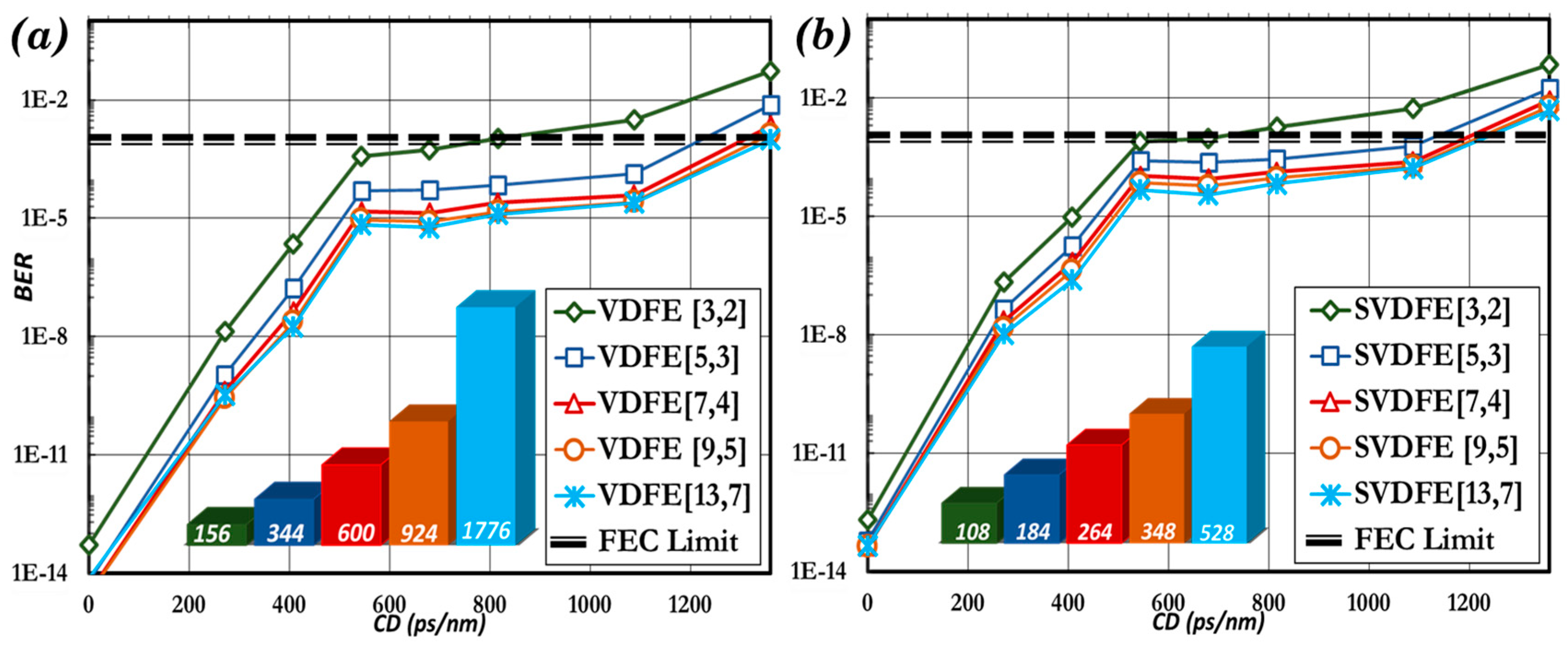
increase, the performance of the equalizer in compensating chromatic dispersion improves. In
Figure 6 the performance of VDFE and SVDFE equalizers for different sets of [
Mf,
Mb] are presented accompanied with the total number of coefficients used for each case. It has become evident that, for both VDFE and SVDFE, large numbers of
Mf and
Mb (e.g., [13,7] and [11,6]) result in a dramatic increase of the number of coefficients but does not result in a notable increase in performance compared to the equalizers with smaller values of [
Mf,
Mb] (e.g., [9,5]).
When electronic equalization is used in conjunction with optical compensation, as in the cases suggested here, the memory of the FF and the FB part of VDFE type equalizers does not need to be high, and VDFE[
Mf,
Mb] with [
Mf,
Mb] = [5,3] and [9,5] are sufficient [
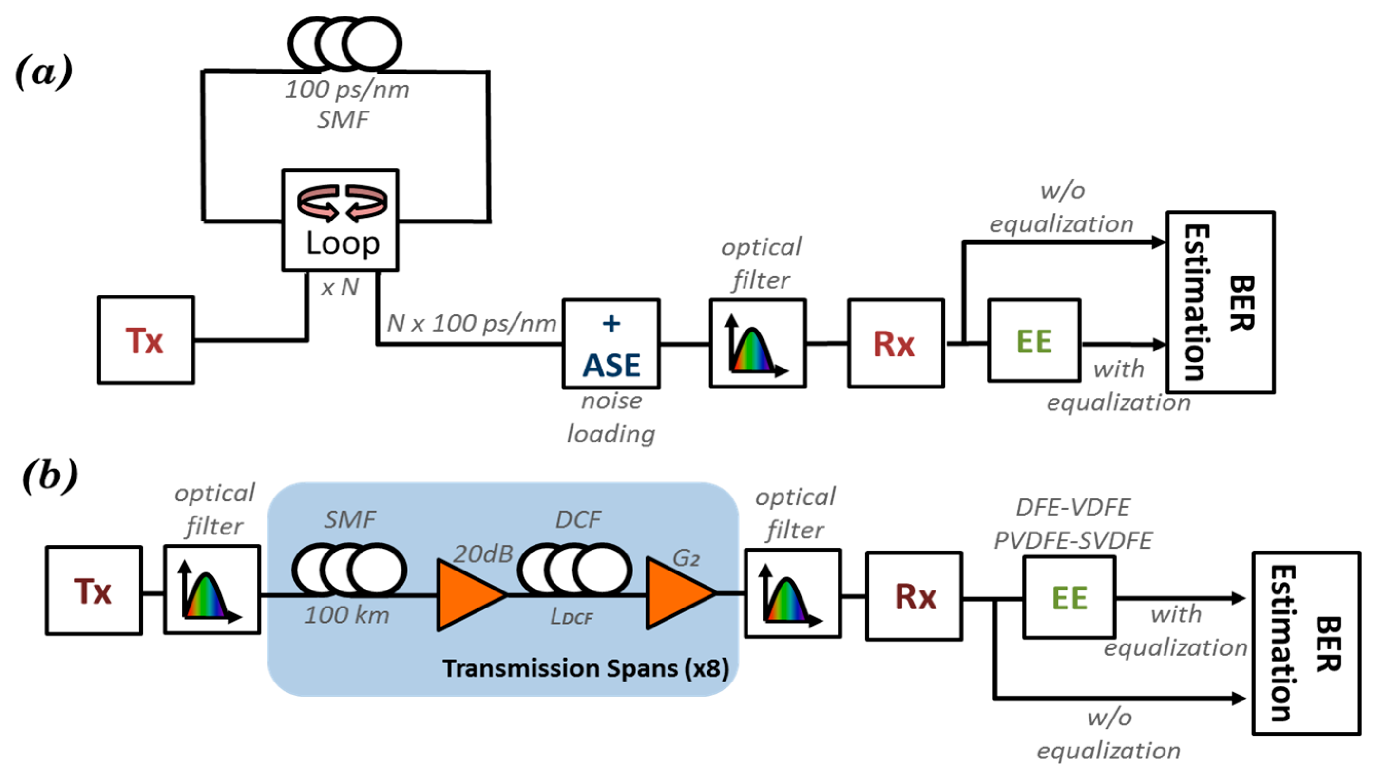
2]. As a result, the performance of the optical communications system can be significantly improved, in the sense of reaching an extended transmission distance, or by improving the bit error rate (BER) of the received signal. In order to provide the whole picture about the suggested electronic equalization solution, their efficiency is evaluated by means of two different numerical modeling sets of an optical link that operates at 40 Gb/s using a DQPSK modulation format (
Figure 7).
The first modeling setup (
Figure 7a), referred hereafter as noise loading scenario, utilizes the OSNR metric to evaluate the performance of the optical transmission system, which can be defined as:
Any variation of the OSNR subsequently leads to variation in the quality and, hence, the BER value of the detected signal. Thus, the OSNR requirement to achieve a specific BER (referred as rOSNR) can provide a figure of merit for the performance of a system. The performance of each receiver/equalizer combination in an optical transmission system is evaluated through modelling of an uncompensated link, which consists of a single mode fiber, without utilizing any optical dispersion compensating module. While SMF is considered lossless, the total accumulated dispersion varies from 100 ps/nm to 1500 ps/nm. The OSNR value varies by adding Gaussian-distributed optical white noise before the optical receiver emulating various levels of amplified spontaneous emission (ASE) at the receiver end, while a bandwidth of B0 = 12.5 GHz is used to calculate the OSNR value. On the receiver side a bandpass optical filter with 40 GHz bandwidth is used to reduce the ASE noise that enters the MZDI and subsequently the PIN.
For the second setup (
Figure 7b), a multi-span transmission link is numerically simulated, which consists of eight identical spans (8 × 100 km) where a partial compensation of the accumulated dispersion is performed by the means of DCF, while the residual dispersion is handled by the electronic equalizer. A metric that defines the amount of the optical dispersion compensation is introduced, called the optical compensation ratio, hereafter denoted as OCR, and varies from 80% to 99% of the total accumulated dispersion. For the simulations, each span consists of an SMF with D = 17 ps/nm/km, attenuation parameter of a = 0.2 dB/km, and a DCF with a dispersion parameter D = −85 ps/nm/km and a = 0.5 dB/km. The fiber model uses the split step Fourier method in order to solve the nonlinear Schroedinger (NLS) equation, taking into account fiber nonlinearities and the nonlinear coefficient n
2 has a value of 2.6 × 10
−20 m
2/W while PMD is not considered. Moreover, a two-stage amplification process is used, modelled by two separate amplifiers with a 5 dB noise figure, each one of them utilized to compensate either the SMF or the DCF losses. For both of the aforementioned set up scenarios the transmitter/receiver configuration is considered identical. At the transmitter side, the DQPSK signal is generated via two different MZM (one per channel) which operate in a push-pull mode and have an extinction ratio of 35 dB each. In terms of electrical filtering two low pass third-order Bessel filters are used with a cut-off frequency of 40 GHz. For the PRBS, the modified Wichman-Hill generator [
26] is used with a mark probability of 0.5. The transmitter operates at the optical frequency of 193.1 THz with 0 dBm output power. On the receiver side, an optical filter of 40 GHz bandwidth with a third-order Gaussian frequency response is utilized. In order to demodulate the DQPSK signal, two different MZDI are used. After each MZDI output port a photodiode of 1 A/W responsivity and a fourth-order Bessel frequency response electrical filter is used in order detect the optical signal. The input power is chosen to be well above the noise limit and below the nonlinear limit of the system. It is noted, however, that in a realistic system where WDM is used and the number of channels increases, the optical power and crosstalk will be dominant, and the parameters will be re-evaluated.
The numerical simulations are performed by the means of Virtual Photonics Inc. software (VPI Transmission Maker) and approximately 106 bits are used for BER computation, in order to achieve higher accuracy.
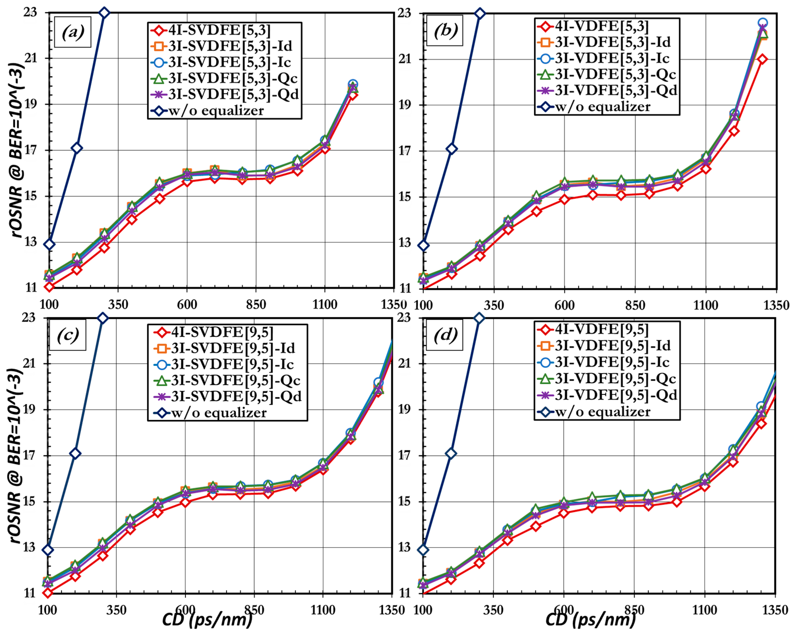
The results of the noise loading scenario of each equalizer (SVDFE and VDFE) are depicted in
Figure 8 for both [
Mf,
Mb] = [5,3] and [9,5]. The specific sets of [
Mf,
Mb] exhibit sufficient compensation capability, and the equalizer complexity makes it feasible in terms of implementation [
2]. The required OSNR with respect to accumulated dispersion is plotted for all equalizer cases discussed in
Section 2 and
Section 3, along with the performance of the optical system when dispersion compensation is performed only by optical means (without the equalizer case). Apart from the single-ended joint version, where all four output ports are utilized (denoted in figures as 4I), each equalizer is compared with all three partially-joint input counterparts (denoted in figures as 3I). Those partially-joint single-ended configurations differentiate themselves according to the number of ports (e.g., 3I three input) and the specified disregarded input port (e.g., 3I-VDFE[5,3]-
Id). Depending on the output that is not utilized, every configuration exhibits slightly different performance. All of the different configurations seem to offer a significant improvement in the performance of the system under investigation, compared to the case where no electronic equalization is used (without equalizer). Assuming that the rOSNR should be approximately 18 dB, 4Ι equalization schemes seem to increase the amount of tolerable CD up to 1200 ps/nm (SVDFE[5,3]) and 1325 ps/nm (VDFE[5,3]), corresponding to 70 km and 80 km of uncompensated fiber, respectively. The increase of the tolerable amount of CD is even greater when equalizers with [
Mf,
Mb] = [9,5] are deployed. When no equalization is used the tolerable amount of chromatic dispersion reaches up to 300 ps/nm (corresponding to 17 km of uncompensated CD), hence, utilizing equalization can extend the uncompensated distance approximately up to 60–80 km (depending on the equalizer type and the set of [
Mf,
Mb]). This improvement on the CD tolerance of the system comes at the expense of increased required OSNR, since as the amount of residual dispersion increases, the value of rOSNR increase also. The rOSNR deterioration is saturated at 600 ps/nm, indicating that the equalizer is slowly reaching its full potential in terms of alleviating the residual CD. Although every equalizer succeeds in ensuring the proper operation of the system (by achieving a BER of 10
−3), for a certain amount of additional dispersion there is point where the increase in the required OSNR becomes dramatic and the performance is deteriorated. From
Figure 8 it becomes evident that although the best efficiency is achieved by the four-input joint single-ended VDFE and SVDFE, all three-input partially-joint alternatives exhibit marginal differences in performance.
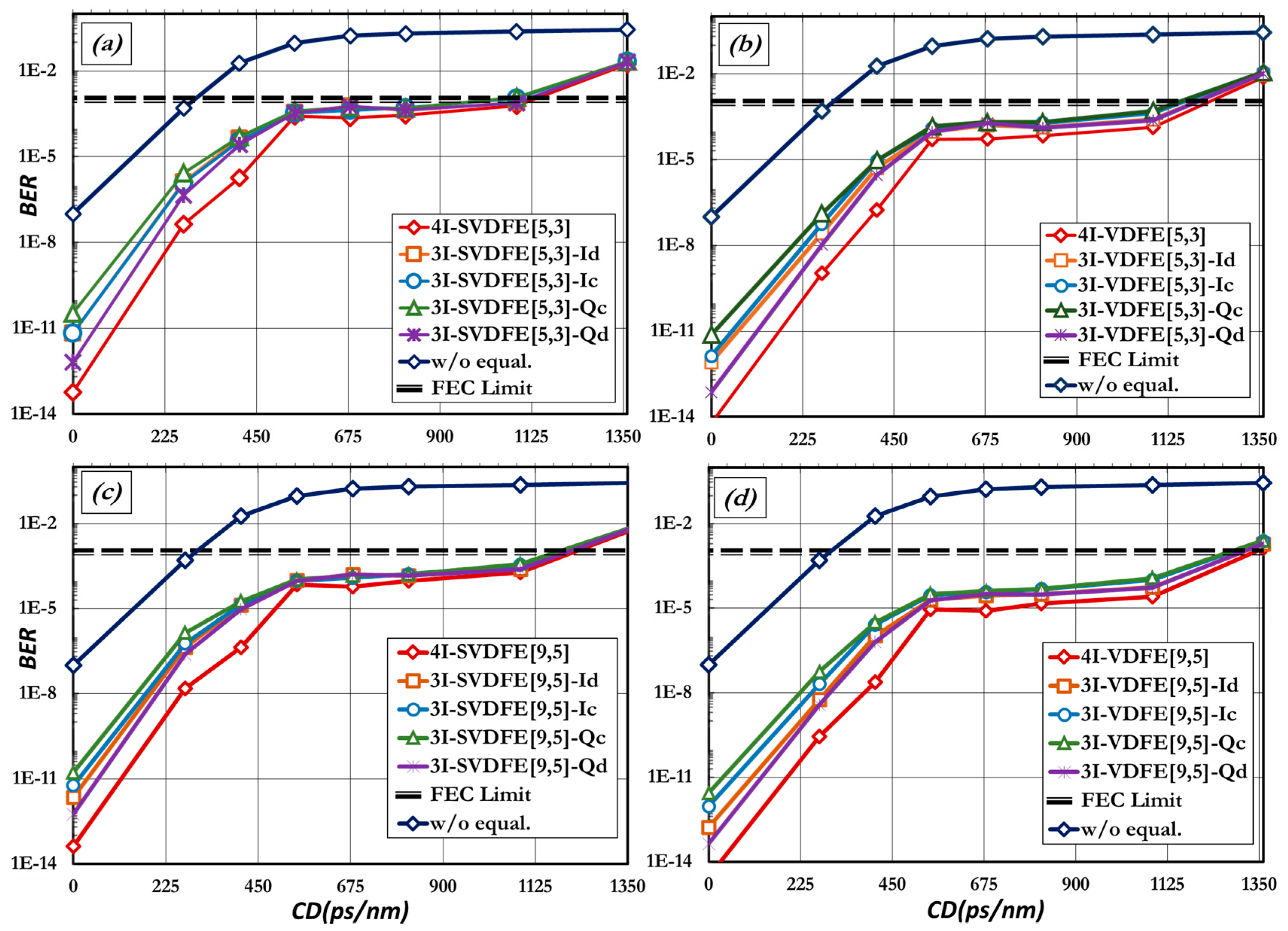
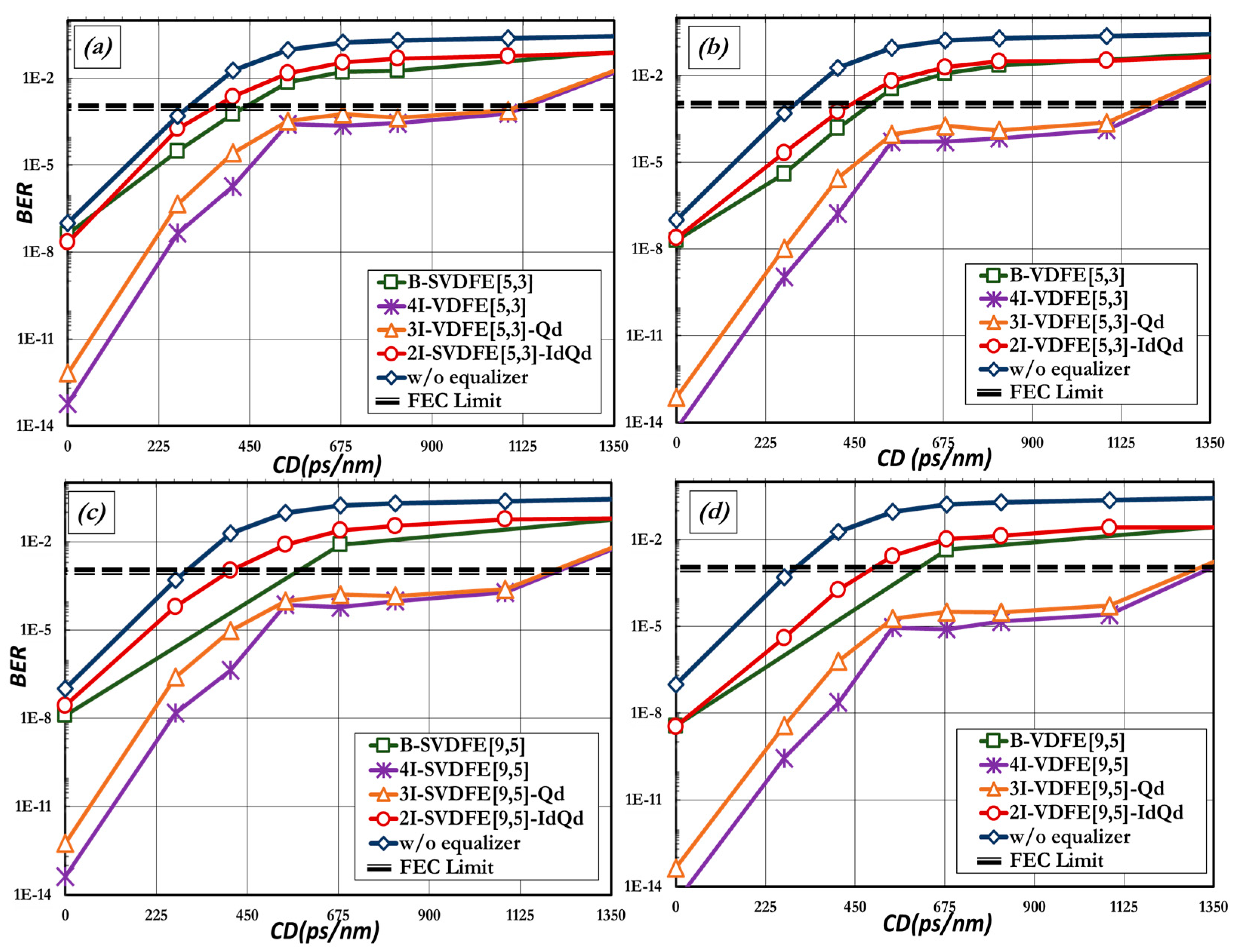
All of the aforementioned conclusions can also be verified by the results that are derived by the numerical modeling of the multi-span transmission system shown in
Figure 7b and are depicted in summary in
Figure 9. The OSNR of this specific transmission system is approximately 18 dB measured at a bandwidth of 12.5 GHz. In this case the BER of the signal received after equalization is estimated and presented with respect to the variable amount of chromatic dispersion that emerges due to the partial optical compensation (OCR = 80%–99%). These performances are presented along with the case where no electronic equalization is used (without equalizer) and the FEC (Forward Error Correction) limit = 10
−3.
Nonetheless, apart from the minor differences in the performance of all of the possible candidates, one can conclude that the solution of utilizing an equalization scheme that ignores branch
Qd can offer the best trade-off between complexity and efficiency. On the contrary, all equalizers that ignore
Qc output seems to experience the worst performance although its difference in efficiency is still marginal. Similarly, regarding the I channel of information, ignoring the
Id port instead of the
Ic port presents better performance. Τhis feature can be justified by noting that the constructive output port is resembles a duobinary (DB) signal, while the destructive output port resembles an alternating-mark-inversion (AMI) signal [
27,
28]. The intrinsic high tolerance of the DB modulation format in chromatic dispersion originates from its narrow spectrum [
29] and can explain the better performance of every equalizer when the constructive, rather than the destructive, port (of each channel) is maintained to undergo the process of equalization [
30].
Since ignoring the destructive output port of each channel (
I or
Q) seems to be the most efficient solution among the partially joint configurations in terms of alleviating the CD effect, it becomes of interest to investigate the performance of a degenerated equalizer in which the destructive outputs of both
I and
Q channel are ignored, resulting in a two-input partially-joint equalizer (denoted here after as 2
I). The two-input partially-joint equalizer offers the lowest complexity among all of the different single–ended receiver configurations. In order to provide a fair comparison in terms of efficiency, the performance of the two-input partially-joint equalizer is presented along with the performance of the balanced receiver/equalizer combination [
2], considering that the complexity of the configurations are also comparable.
Ιn
Figure 10 the estimated BER of the two-input configuration for every equalizer is depicted, along with the performance of balanced configuration, in respect to variable amounts of residual dispersion. The complexities of balanced and two-input equalization are comparable and the performance of the balanced scheme surpasses the one offered by the two-input partially-joint single-ended configuration for every type of equalizer (SVDFE, VDFE) and for all sets of [
Mf,
Mb]. However, the superiority of balanced equalization becomes more evident as the values of
Mf and
Mb increase. It should be highlighted that the balanced VDFE[9,5] (i.e., B-VDFE[9,5]) is able to alleviate up to 630 ps/nm of residual dispersion and, thus, almost doubles the dispersion tolerance of the optical system, compared to the case where the compensation is performed only with optical means, whereas the equivalent two-input partially-joint equalizer (2I-VDFE[9,5]-IdQd) that carries the same complexity can reach dispersion tolerance values up to ~500 ps/nm. The performances of four-input and three-input equalizers exceed, by far, those offered by the two-input partially-joint and balanced equalizers and are presented here only for completeness.
Disregarding inputs from the equalization process proved to be exceptionally efficient when compared against the performance of four-input joint single-ended equalizers on one hand, and low complexity balanced receiver equalizers on the other. The first case exhibits high performance, high complexity, and questionable numerical accuracy. High complexity is dictated by the number of filters that are used. Furthermore numerical accuracy is compromised by the linear dependency of the optical inputs that leads to high condition numbers in the equalization process. The balanced case exhibits low performance, but very low complexity and cost. In this paper, starting from the requirements for low-complexity, high-performance equalizers, the effect of reducing the number of single-ended ports in the equalization process is investigated with exceptional results. Due to the nature of DQPSK, when one of the destructive ports is not utilized in the equalization process, even low-complexity VDFE equalizers manage to compensate for residual dispersion. However, it has been proved that when it comes to ignoring more than one input at the same time (i.e., both destructive input ports) the performance of the balanced equivalent is superior, especially as the filter memory of the FF and FB part increase. When deployed in multi-span systems, three-input partially-joint SVDFE equalizers can stretch 40 Gb/s DQPSK transmission systems beyond 800 km with very good performance and 25% lower complexity than four input joint equalization counterparts.
