Article

Widely Tunable Monolithic Mid-Infrared Quantum Cascade Lasers Using Super-Structure Grating Reflectors

1
Department of Computer Science and Electrical Engineering, University of Maryland, Baltimore County, 1000 Hilltop Circle, Baltimore, MD 21250, USA
2
Department of Electrical Engineering, National Taiwan University, Taipei 10617, Taiwan
3
Department of Physics, University of Maryland, Baltimore County, 1000 Hilltop Circle, Baltimore, MD 21250, USA
*
Author to whom correspondence should be addressed.
Photonics 2016, 3(2), 25; https://doi.org/10.3390/photonics3020025
Submission received: 1 April 2016 / Revised: 28 April 2016 / Accepted: 29 April 2016 / Published: 3 May 2016
(This article belongs to the Special Issue Quantum Cascade Lasers - Advances and New Applications)

Abstract

:
A monolithic, three-section, and widely tunable mid-infrared (mid-IR) quantum cascade laser (QCL) is demonstrated. This electrically tuned laser consists of a gain section placed between two super structure grating (SSG) distributed Bragg reflectors (DBRs). By varying the injection currents to the two grating sections of this device, its emission wavelength can be tuned from 4.58 μm to 4.77 μm (90 cm−1) with a supermode spacing of 30 nm. This type of SSG-DBR QCLs can be a compact replacement for the external cavity QCL. It has great potential to achieve gap-free and even further tuning ranges for sensor applications.

1. Introduction

Optical sources in the mid-infrared (mid-IR) wavelength range are important for applications including trace gas sensing, explosive detections, spectroscopy and free space communications [1,2,3,4]. Mid-IR quantum cascade laser (QCL) is in unique position to be utilized for these applications. It went through significant development in terms of efficiency, wavelength coverage and testing methods in the past decade to achieve room-temperature, continuous-wave (CW) operation and high power performances [5,6,7]. If the wavelength of a QCL can be widely tunable, we can further use it to target multiple gas species with different absorption wavelengths in trace gas sensing applications. Furthermore, a tunable QCL has the potential to perform like a Fourier transform infrared (FTIR) spectrometer which provides much higher resolution and measurement sensitivity due to its narrower linewidth and higher output intensity compared to that of an IR lamp.
There are mainly three types of tunable QCLs being used: External Cavity tunable QCL (EC-QCL), Distributed Feedback QCL (DFB-QCL) and Distributed Bragg Reflector QCL (DBR-QCL). Among them EC-QCL is currently most widely used source in trace gas sensing. Its tuning is achieved using an external-cavity (EC) grating operated in the Littrow condition [8]. Even though a wide tuning range (e.g., 432 cm−1) has been reported, the EC-QCL system is usually bulky and requires high precision optical alignment. Vibration caused instability has also been a major issue. Furthermore, the mechanical tuning method limits wavelength tuning speed and the setup is susceptible to significant coupling losses.
For DFB-QCL and DBR-QCL, periodic gratings are etched into the laser waveguide (DFB-QCL), or into a section adjacent to the gain section to form a distributed Bragg reflector (DBR-QCL). Single mode emission can be achieved with the grating for filtering and mode selection. Wavelength tuning is controlled by refractive index change at both the active region and the grating region. The refractive index is mainly temperature dependent and it can be changed either by varying the heat sink temperature or by applying a small current to the active region. For DFB-QCL, the single-mode wavelength can be tuned ~20 cm−1 via heat sink temperature scan and or tuned ~3 cm−1 through fast Joule heating with an injection current [9]. For DBR-QCL, a tuning range over 30 cm−1 has been achieved by varying the heat sink temperature or direct current injection to the grating section [10,11]. Comparing to EC-QCLs, both DFB and DBR QCLs are integrated, compact in size and have minimal coupling losses between the gain and grating sections. However, due to limited spectral tuning range compared to EC-QCL, DFB or DBR-QCLs are typically designed to target absorption spectrum of one specific molecule with narrow, well-resolved rotational-vibrational absorption lines.
In order to further extend the DFB/DBR-QCL tunability and exploit the full bandwidth of the QC gain medium, multiple schemes have been proposed and demonstrated. One such scheme is to mount multiple DFB-QCLs into one chip. The DFB-QCLs in the array are spectrally apart and the laser outputs are optically combined in the far field [12]. Some other schemes are related to change the grating structure to form a ‘sampled grating’ on a single DFB/DBR-QCL [13,14,15]. The sampled grating DBR-QCL (SG-DBR-QCL) has separated gain and grating sections [13,14], which can adjust output wavelength and power independently. A wide tuning range of 100 cm−1 has been achieved [14] and eliminates the need for beam combining. For the double DFB sampling grating tunable QCL structure, two DFB lasers with two sampling gratings are coupled together as one cavity [15,16]. Since the total length of the device is 9 mm long, providing gain for the grating sections has the advantage to help to compensate the long waveguide loss, which, in turn, helps to extend the tuning range. Thus, when equipped with a very high gain material, a large wavelength coverage range of 236 cm−1 was demonstrated [16]. However, using gain to compensate the loss of the grating waveguide section will lead to some well-known problems, where the output power and wavelength are coupled together. As a result, every adjustment of output power will lead to a change of the whole set of relationship between output wavelength and the front and back tuning currents. Furthermore, tuning sensitivity and stability at each wavelength have a multidimensional dependence on the sampling grating reflectivity, facet reflectivity, and gain from both sections, which make them difficult to be optimized. The complexity of power and wavelength control as well as calibration can become a highly time-and effort consuming task for system applications.
The sampled grating used in References [13,14,15] is simply a grating with part of it being periodically removed. It is easy to fabricate but the produced reflectivity spectrum is not ideal. As shown in Figure 1a, the reflection spectrum of such binary sampling grating does not have a flat top profile, which will limit its tuning range to the high reflectivity region only [13,17]. The spectrum is centered at the Bragg wavelength (λB), the spacing between the modes is inversely proportional to the grating superperiod (Λs), and the spectrum envelope widens as the ratio between the grating burst and the grating superperid (Λ1s) is reduced. Thus, small duty cycle gratings are required for a large number of satellite peaks in the spectrum. However, reducing the duty cycle also reduces the effective grating coupling coefficient, κeff, which decreases the peak reflectivity. As a result, even for QCLs with board gain bandwidth (250 cm−1 in Reference [13]), the tuning range cannot go beyond the sampled grating reflectivity bandwidth.
In this paper, we proposed and demonstrated the use of super structure grating (SSG) on DBR-QCLs. The structure and reflection spectrum of the SSG is shown in Figure 1b. It can achieve a more flat and rectangular profile, which may extend the tuning range to it full sampling spectrum [18,19]. The SSG structure is based on linear chirping in the grating pitches from Λa to Λb within a large period of Λs. The Fourier components of the structure leads to a spectrum with high-reflection peaks in the wavelength range from λb (=2neqΛb) to λa (=2neqΛa). The reflection peak spacing Δλ = λ02/2neqΛs, where the neq is the equivalent refractive index of the waveguide and λ0 is the average Bragg wavelength. Compared to the binary sampling grating, the SSG grating achieve a much wider tuning range to take full advantage of the QCL gain bandwidth.
A schematic diagram of the SSG-DBR QCL is shown in Figure 2a. The device has three sections, which consist of a standard Fabry-Pérot gain section, a front SSG-DBR section and a rear SSG-DBR section. All three sections share the common active core and can be independently biased. The two SSG section operate as passive wavelength-selective reflectors and their refractive index can be controlled independently by adjusting the local temperatures. The local temperatures can be controlled by current injection to either SSG section or by mounting or integrating small heating/cooling devices to the sections [10,20,21].
As shown in Figure 2b, multiple reflection peaks are produced in both SSG sections (black solid line from the front SSG section and red dot line from rear SSG section). The mode spacing is designed to be slightly different for each of the two reflectors. Only one matched longitudinal mode from reflection satellite peaks of the two SSGs, is selected as the lasing oscillation mode.
For no tuning, the current applied to both SSG sections are set to be zero and only the center mode is selected as shown in Figure 2c. For coarse tuning, the tuning current is injected to one side of the SSG sections. Figure 2d shows that injecting the current into the rear SSG section (narrower SSG mode spacing) shifts its reflection peaks (the red dot line) to a longer wavelength and cause the matched reflection peak wavelength to hop to longer wavelength as circled. Figure 2e shows that injecting the current into the front SSG section (wider SSG mode spacing) shifts the matched reflection peak wavelength to a shorter wavelength as circled. In this mechanism, the oscillation wavelength can be broadly tuned even if the change of the refractive index is small. For fine tuning, the tuning current is injected to both SSG sections and allowing the matched reflection peak wavelengths continuously fill up the SSG mode spacing.
In following sections, we describe the implementation of the SSG structure to a QCL emitting around 4.7 μm and achieving around 90 cm−1 tuning range. In Section 2, the detailed SSG grating design based on the coupled mode theory is discussed, followed by the SSG and the laser fabrication process presented in Section 3. The device performance characterization and measurement results including wavelength tuning and tuning efficiency are presented in the Section 4.

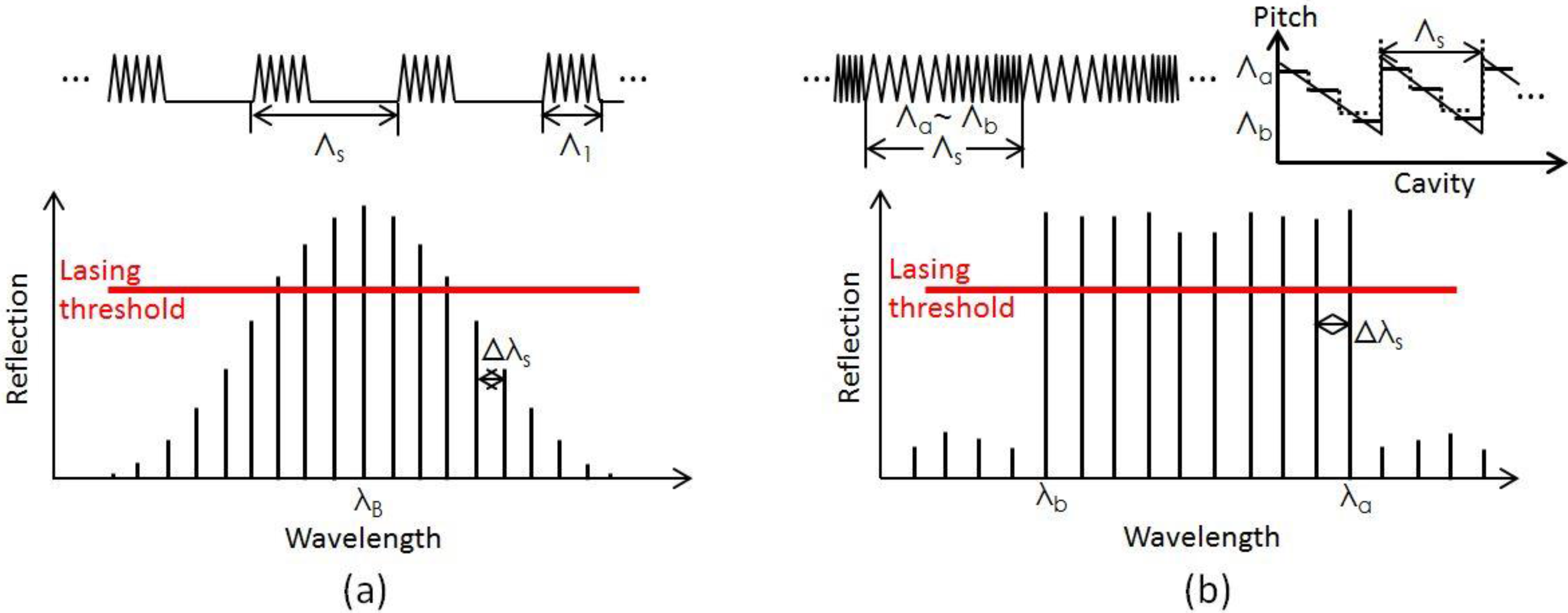
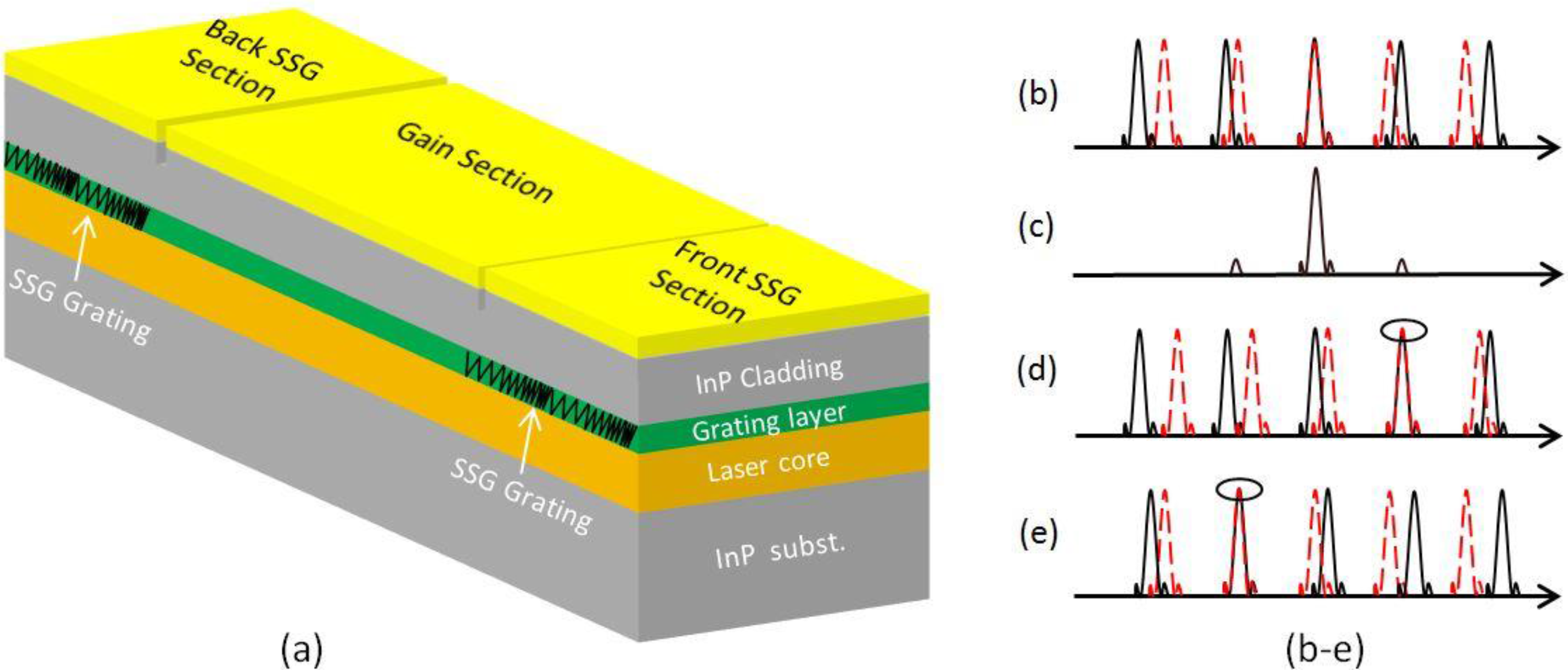
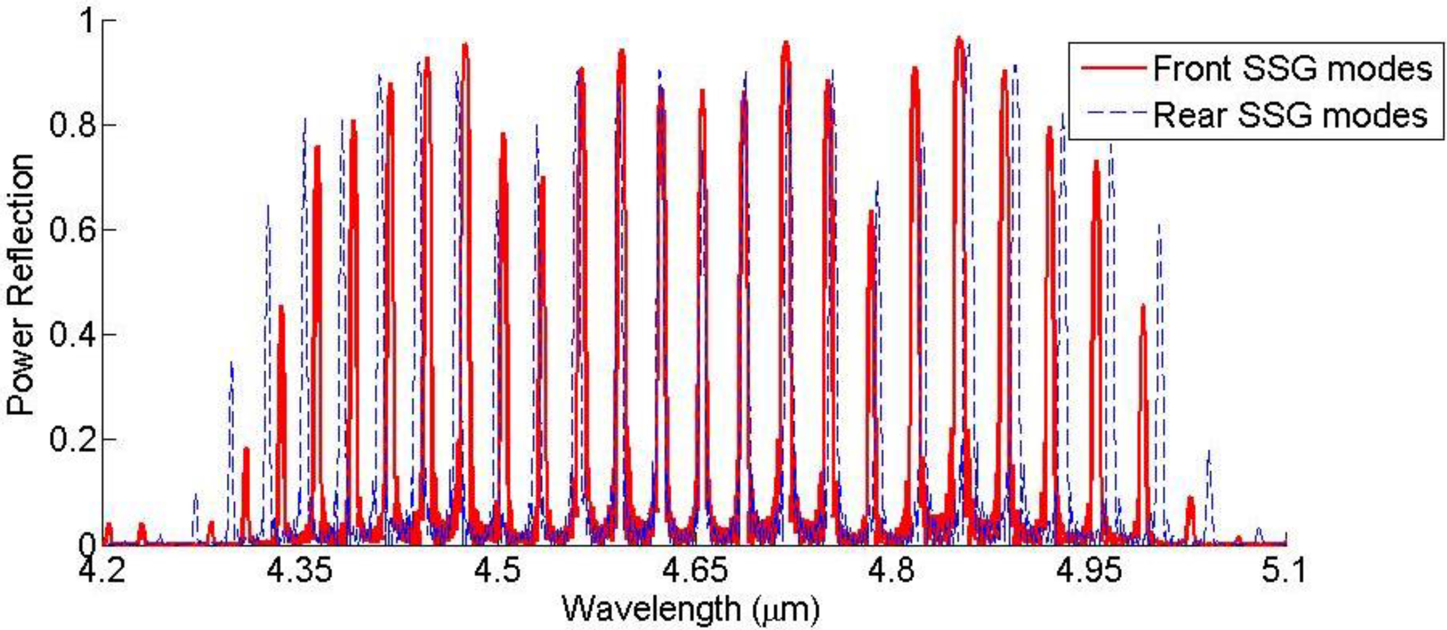
2. Device Design and Simulation

As mentioned earlier, binary sampling grating is easy to fabricate. However, limited by available Fourier components, it will produce a round top reflectivity profile. By applying transfer matrix techniques [22], we can use Fourier design to adjust the structure of SSG and obtain a flat top reflectivity profile, which can push the tuning range to the limit of the gain profile. In our design one SSG period is subdivided into a few small sections, where the grating pitch and depth are assumed to be uniform. The fundamental transfer matrices for each small section can be obtained. We can then determine the characteristics of one SSG period and then the overall SSG-DBR grating waveguides by multiplying these fundamental matrices in certain phase conditions.
An initial design of a 4.65 μm QCL SSG-DBR structures for the front and the rear SSGs and their simulated reflection spectra are described in the following. Both SSGs utilize a 9-period structure and are limited to ~1 mm long. Each SSG period contains 5 different sections and each section has its own grating pitches. The pitches of the back SSG are adjusted slightly from the front SSG to produce different reflection satellite peak spacing (31.17 nm and 32.25 nm for the front and rear SSGs respectively). By independently adjusting individual length of each section we can modify the reflectivity profile of SSGs so that their satellite peaks can have nearly equal heights in the desired turning range centered at the 4.65 μm. The detailed design parameters are listed in Table 1.
The SSG grating serves to enhance the cavity reflectivity and reduce threshold gain at designed wavelengths. Due to the on/off (yes/no) nature of the binary sampling gratings, under the same grating etching depth their equivalent κ is smaller than that of the SSG. Figure 3 shows the simulated SSG reflectivity profiles. Both the front and rear SSG modes are centered at 4.65 μm. There is only a small mode spacing difference between the two sets of reflection peaks. Between 4.35 μm to 4.95 μm there are more than 20 peaks over 50% reflectivity and more than 13 peaks over 80% reflectivity, provides good wavelength selectivity over a wide wavelength range.
Compared to binary sampling grating, the SSG can produce stronger reflection and squarer reflectivity profile, which can lead to wider tuning range under the same grating etching depth.

3. Device Fabrication

The QCL used in the experiment has an active region similar to the structure described in Ref. [23] (λ ≈ 4.7 μm). An n-In0.53Ga0.47As (Si, 5 × 1016 cm−3) grating layer of ~300 nm thick was grown on top of the active region. A Si3N4 layer with a thickness of ~100 nm was deposited on top to grating layer using plasma-enhanced chemical vapor deposition (PECVD). On top of the nitride layer, a ~300 nm PMMA photoresist layer was spin coated for followed e-beam writing.
Both front and rear SSG gratings were patterned into the photoresist layer by e-beam lithography (Raith eLine system). The detailed structure of the gratings was described in Table 1. Figure 4 shows part of the front SSG section after the surface photoresist is developed. Five different piecewise variable gratings can be easily found in one SSG period.
The photoresist pattern was transferred to the underneath Si3N4 layer by using CF4 dry etching (Oxford Plasmalab system). The patterned Si3N4 layer was then used as mask for etching the top InGaAs cladding layer. The grating etch is done by using Cl2/N2 dry etching (Oxford Plasmalab system). N2 gas was added to serve as the sidewall passivation [24,25]. Several other gas combinations can also be used to selectively etch the InGaAs over Si3N4 [26,27,28]. The gas flow, etching power, chamber pressure, and sample temperature have to be optimized to achieve high etching selectivity over Si3N4, smooth etched surface, high etch rate, and minimum sidewall undercutting etching to achieve ~50% grating duty cycle. A SEM photo of the etched InGaAs grating is shown in inset of Figure 4.
The sample with etched InGaAs gratings was thoroughly cleaned before the followed cover growth done with metal organic chemical vapor deposition (MOCVD). The cap layers include a 2.5 µm thick low doped (1 × 1017 cm−3) upper waveguide cladding layer, a 1 µm thick high doped (1 × 1019 cm−3) plasmon-enhanced confinement layer, and 100 Å heavily doped (>1019 cm−3) contact layer. After the cover growth, the sample followed a standard buried-heterostructure (BH) fabrication process to form 10–12 μm wide waveguide with both optical and electronic confinements [29]. Ti/Au was used for top and bottom metallization. The samples were then cleaved and scribed to 4 mm long and 0.5 mm wide individual SSG-DBR QCL devices. The laser gain section is ~2 mm long located at the center of the device. The front and back SSG DBR sections are both ~1 mm long. Additional electrical isolation channels were etched between laser gain sections and grating sections to reduce the conductance between them. Both sides of the laser facet were un-coated for simplicity. The SSG-DBR QCLs were then mounted epi-side-up on copper heat sinks for testing.

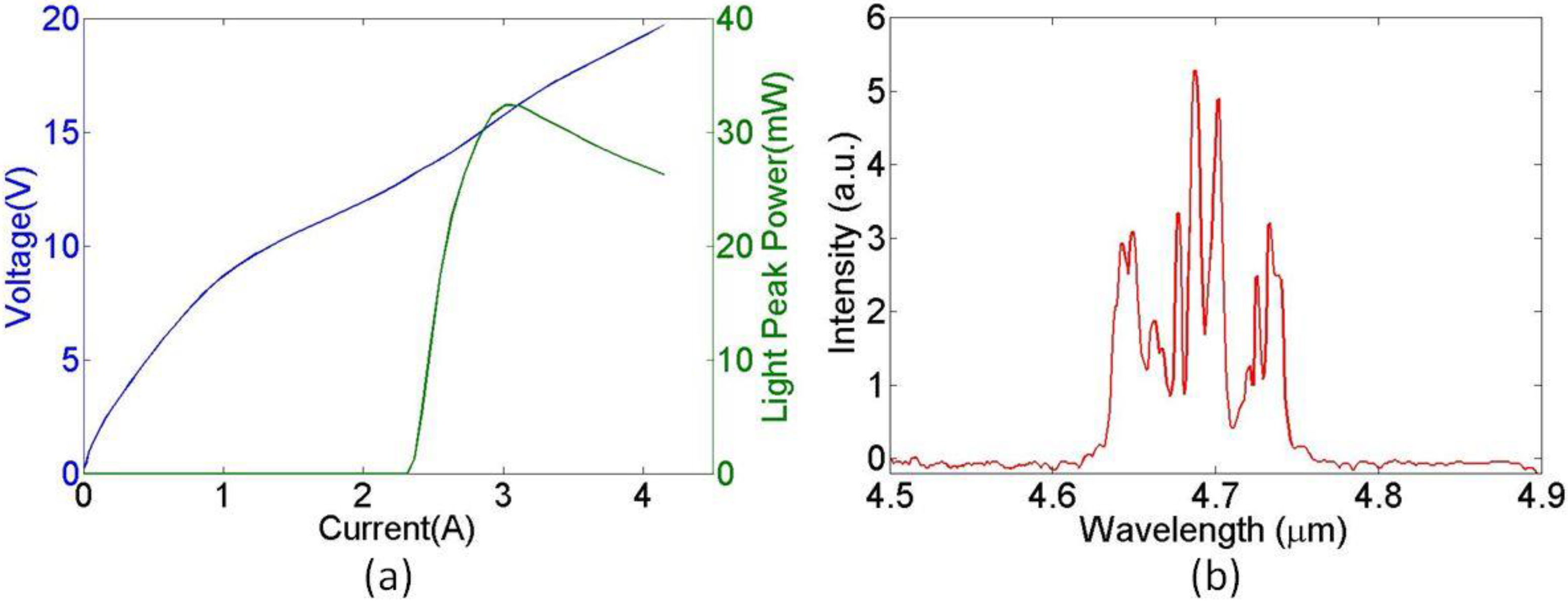
4. Experimental Results

For laser measurement, we first tested the LIV curve of the 4 mm long SSG-DBR laser. All three sections of the laser were simultaneously pumped with 500 ns long electrical pulses at a repetition rate of 10 kHz. As shown in Figure 5a, the laser has a threshold of 2.3 A and a peak power of 32 mW at 2.9 A. The high lasing threshold is mainly due to its higher waveguide loss of the long laser cavity. We then measured the emission spectrum of a 2 mm long Fabry-Pérot laser from the same batch. As shown in Figure 5b, with no SSG mirror and the Fabry-Perot laser was pumped well above its lasing threshold (1 A), the FTIR measured spectrum has a broad envelope centered at a wavelength around 4.7 μm. The lasing modes are distributed over a range of 100 nm from 4.65 μm to 4.75 μm and the mode powers are not evenly distributed.
For the tuning experiment, the laser gain section and the grating sections are driven by different pulse generators with very low crosstalk. The pulse current applied to the gain section was kept at a frequency of 10 kHz, a pulse duration of 500 ns, and an amplitude of 2.6 A. The electrical pulses applied to the grating sections were synchronized and overlapped with the gain section pulses, they were kept at same repetition rate at 10 kHz with pulse durations of 50 μs, which are ~50% duty cycles.
By changing the pumping current amplitude to the grating sections, the laser spectra were recorded by an FTIR. Firstly, we leave the rear grating section un-pumped and fixed the pumping current to the gain at 2.6 A, which is above the lasing threshold current. The front grating section was then pumped from 0 mA to 350 mA at room temperature. The center wavelength of the SSG-DBR QCLs was tuned from 4.64 μm to around 4.77 μm with a four-time supermode change as shown in Figure 6c–e. The spacing between the supermodes is around 30 nm as designed and the overall current dependence of emission wavelength is +0.37 nm/mA. The elevated temperature induced by the pumped current changes the front grating refractive index and therefore shifts its mode to find a match with that of the rear grating mirror.
Then, we leave the front grating section unpumped and pump the rear grating section from 0 mA to 350 mA at room temperature. The center wavelength of the SSG-DBR QCLs was tuned from 4.64 μm to around 4.58 μm with two mode hops as shown in Figure 6a–c. The overall current dependence of emission wavelength is −0.17 nm/mA.
The emission wavelength of the SSG-DBR QCL is controlled by varying the injection currents to the two grating sections. The wavelength can be tuned as much as 60 cm−1 to the longer wavelength side and as much as 30 cm−1 to the shorter wavelength side, the total tuning range is 90 cm−1. Therefore, the wavelength can be tuned from 4.58 μm to 4.77 μm (90 cm−1) with a supermode spacing of 30 nm. This nonsymmetrical tuning is because the designed SSG refection spectrum center (4.65 μm) is not aligned with the laser gain profile center at 4.7 μm. At any given time, the laser can always achieve single mode operation. However, in some cases the spectra show insufficient side-mode suppression, which may be a combined result of multiple spectra from different tuning time and non-ideal FTIR scanning velocity setting taking place within a long FTIR plotting time of a few 10s seconds.

5. Summary and Outlook

In the above sections, we discussed the design, fabrication and testing of the proposed three-section SSG-DBR QCLs. Furthermore, we have demonstrated the emission wavelength of the device can be controlled by varying the injection current to each of the two grating sections, yielding a tuning range of 90 cm−1, from 4.58 μm to 4.77 μm, which is limited by the gain material available to us. Our device is intended to be a proof of principle that wider and only gain limited tuning can be accomplished with SSG based tunable QCLs and it can be used as a compact solution for trace-gas sensing applications.
In the future, better active materials with higher and wider gain profile, new SSG mirror design and facet AR coating will be exploited to improve the wavelength tuning range and side-mode suppression ratio (SMSR).

Acknowledgments

The authors thank NSF MIRTHE ERC to support the work and Robert J. Weiblen for useful discussions.

Author Contributions

“Dingkai Guo and Fow-Sen Choa conceived and designed the experiments; Jiun-Yun Li fabricated the mask set, Dingkai Guo performed the device design and fabrication experiments; Liwei Cheng, Xing Chen and Terry Worchesky helped the device testing, Dingkai Guo wrote and Fow-Sen Choa revised the paper.”

Conflicts of Interest

The authors declare no conflict of interest.

References

  1. Kosterev, A.; Wysocki, G.; Bakhirkin, Y.; So, S.; Lewicki, R.; Fraser, M.; Tittel, F.; Curl, R.F. Application of quantum cascade lasers to trace gas analysis. Appl. Phys. 2008, 90, 165–176. [Google Scholar] [CrossRef]
  2. Chen, X.; Cheng, L.; Guo, D.; Kostov, Y.; Choa, F.-S. Quantum cascade laser based standoff photoacoustic chemical detection. Opt. Express 2011, 19, 20251–20257. [Google Scholar] [CrossRef] [PubMed]
  3. Chen, X.; Guo, D.; Choa, F.-S.; Wang, C.-C.; Trivedi, S.; Snyder, A.P.; Ru, G.; Fan, J. Standoff photoacoustic detection of explosives using quantum cascade laser and an ultrasensitive microphone. Appl. Opt. 2013, 52, 2626–2632. [Google Scholar] [CrossRef] [PubMed]
  4. Martini, R.; Whittaker, E.A. Quantum cascade laser-based free space optical communications. J. Opt. Fiber. Commun. Rep. 2005, 2, 279–292. [Google Scholar] [CrossRef]
  5. Bai, Y.; Slivken, S.; Darvish, S.R.; Haddadi, A.; Gokden, B.; Razeghi, M. High power broad area quantum cascade lasers. Appl. Phys. Lett. 2009, 95, 221104. [Google Scholar] [CrossRef]
  6. Lyakh, A.; Maulini, R.; Tsekoun, A.; Go, R.; Patel, C.K.N. Multiwatt long wavelength quantum cascade lasers based on high strain composition with 70% injection efficiency. Opt. Express 2012, 20, 24272–24279. [Google Scholar] [CrossRef] [PubMed]
  7. Guo, D.; Cheng, L.; Chen, X.; Choa, F.-S.; Fan, J.; Worchesky, T. Electrical derivative measurement of quantum cascade lasers. J. Appl. Phys. 2011, 109, 043105. [Google Scholar] [CrossRef]
  8. Hugi, A.; Terazzi, R.; Bonetti, Y.; Wittmann, A.; Fischer, M.; Beck, M.; Faist, J.; Gini, E. External cavity quantum cascade laser tunable from 7.6 to 11.4 μm. Appl. Phys. Lett. 2009, 95, 061103. [Google Scholar] [CrossRef]
  9. Gmachl, C.; Straub, A.; Colombelli, R.; Capasso, F.; Sivco, D.L.; Sergent, A.M.; Cho, A.Y. Single-mode, tunable distributed-feedback and multiple-wavelength quantum cascade lasers. IEEE J. Quant. Electron. 2002, 38, 569–581. [Google Scholar] [CrossRef]
  10. Cheng, L.; Chen, X.; Choa, F.-S.; Worchesky, T. Integrated tunable DBR quantum cascade lasers with 30 cm−1 tuning range at 4.7 μm. Proc. SPIE 2010, 7616, 761618. [Google Scholar]
  11. Xie, F.; Caneau, C.; LeBlanc, H.; Coleman, S.; Hughes, L.C.; Zah, C.-E. Pulsed wavelength tuning and continuous wave operation of distributed bragg reflector quantum cascade lasers. Lasers Electro-Opt. (CLEO) 2012. [Google Scholar] [CrossRef]
  12. Lee, B.G.; Zhang, H.A.; Pflügl, C.; Diehl, L.; Belkin, M.A.; Fischer, M.; Wittmann, A.; Faist, J.; Capasso, F. Broadband distributed-feedback quantum cascade laser array operating from 8.0 to 9.8 μm. IEEE Photon. Technol. Lett. 2009, 21, 914–916. [Google Scholar] [CrossRef]
  13. Mansuripur, T.S.; Menzel, S.; Blanchard, R.; Diehl, L.; Pflügl, C.; Huang, Y.; Ryou, J.-H.; Dupuis, R.D.; Loncar, M.; Capasso, F. Widely tunable mid-infrared quantum cascade lasers using sampled grating reflectors. Opt. Express 2012, 20, 23339–23348. [Google Scholar] [CrossRef] [PubMed]
  14. Diba, A.S.; Xie, F.; Gross, B.; Caneau, C.; Hughes, L.C.; Zah, C.-E.; Moshary, F. Application of a broadly tunable SG-DBR QCL for multi-species trace gas spectroscopy. Opt. Express 2015, 23, 27123–27133. [Google Scholar] [CrossRef] [PubMed]
  15. Slivken, S.; Bandyopadhyay, N.; Tsao, S.; Nida, S.; Bai, Y.; Lu, Q.Y.; Razeghi, M. Sampled grating, distributed feedback quantum cascade lasers with broad tunability and continuous operation at room temperature. Appl. Phys. Lett. 2012, 100, 261112. [Google Scholar] [CrossRef]
  16. Slivken, S.; Bandyopadhyay, N.; Bai, Y.; Lu, Q.Y.; Razeghi, M. Extended electrical tuning of quantum cascade lasers with digital concatenated gratings. Appl. Phys. Lett. 2013, 103, 231110. [Google Scholar] [CrossRef]
  17. Jayaraman, V.; Chuang, Z.-M.; Coldren, L.A. Theory, design and performance of extended tuning range semiconductor lasers with sampled gratings. IEEE J. Quant. Electron. 1993, 29, 569–581. [Google Scholar] [CrossRef]
  18. Ishii, H.; Tanobe, H.; Kano, F.; Tohmori, Y.; Kondo, Y.; Yoshikuni, Y. Quasicontinuous wavelength tuning in super-structure-grating (SSG) DBR lasers. IEEE J. Quant. Electron. 1996, 32, 433–441. [Google Scholar] [CrossRef]
  19. Oberg, M.; Rigole, P.; Nilsson, S.; Klinga, T.; Backbom, L.; Streubel, K.; Wallin, J.; Kjellberg, T. Complete single mode wavelength coverage over 40 nm with a super structure grating DBR laser. J. Lightwave Technol. 1995, 13, 1892–1898. [Google Scholar] [CrossRef]
  20. Bismuto, A.; Bidaux, Y.; Tardy, C.; Terazzi, R.; Gresch, T.; Wolf, J.; Blaser, S.; Muller, A.; Faist, J. Extended tuning of mid-ir quantum cascade lasers using integrated resistive heaters. Opt. Express 2015, 23, 29715–29722. [Google Scholar] [CrossRef] [PubMed]
  21. Bidaux, Y.; Bismuto, A.; Tardy, C.; Terazzi, R.; Gresch, T.; Blaser, S.; Muller, A.; Faist, J. Extended and quasi-continuous tuning of quantum cascade lasers using superstructure gratings and integrated heaters. Appl. Phys. Lett. 2015, 107, 221108. [Google Scholar] [CrossRef]
  22. Yamada, M.; Sakuda, K. Analysis of almost-periodic distributed feedback slab waveguides via a fundamental matrix approach. Appl. Opt. 1987, 26, 3473–3478. [Google Scholar] [CrossRef] [PubMed]
  23. Evans, A.; Yu, J.S.; Slivken, S.; Razeghi, M. Continuous-wave operation of λ~4.8 μm quantum-cascade laser at room temperature. Appl. Phys. Lett. 2004, 85, 2166. [Google Scholar] [CrossRef]
  24. Heijden, R.V.D.; Andriesse, M.S.P.; Carlstrom, C.-F.; Drift, E.V.D.; Geluk, E.-J.; Heijden, R.W.V.D.; Karouta, F.; Nouwens, P.; Oei, Y.S.; Vries, T.D.; et al. Deep dry etching process development for photonic crystals in InP based planar waveguides. Proc. SPIE Photonic Cryst. Mater. Nanostruct. 2004, 5450. [Google Scholar] [CrossRef]
  25. Uchiyama, H.; Shinoda, K.; Sato, H.; Take, A.; Taniguchi, T.; Tsuji, S. Smooth and anisotropic dry etching of InGaAlAs using Cl2/N2 ECR plasma. IEEE IRPM 2003, 468–471. [Google Scholar] [CrossRef]
  26. Guilet, S.; Bouchoule, S.; Jany, C.; Corr, C.S.; Chabert, P. Optimization of a Cl2–H2 inductively coupled plasma etching process adapted to nonthermalized InP wafers for the realization of deep ridge heterostructures. J. Vac. Sci. Technol. B 2006, 24, 2381–2387. [Google Scholar] [CrossRef]
  27. Gatilova, L.; Bouchoule, S.; Patriarche, G.; Guilet, S. Addition of Si-containing gases for anisotropic etching of III–V materials in chlorine-based inductively coupled plasma. Jpn. J. Appl. Phys. 2011, 50, 08JE02. [Google Scholar] [CrossRef]
  28. Strasser, P.; Wiiest, R.; Robin, F.; Emi, D.; Jacke, H. Process optimization for dry etching of InP-InGaAsP-based photonic crystals with a Cl2/CH4/H2 mixture on an ICP-RIE. IEEE IPRM 2004. [Google Scholar] [CrossRef]
  29. Cheng, L.; Fan, J.; Janssen, D.; Guo, D.; Chen, X.; Towner, F.J.; Choa, F.-S. Analysis of InP regrowth on deep-etched mesas and structural characterization for buried-heterostructure quantum cascade lasers. J. Electron. Mater. 2012, 41, 506–513. [Google Scholar] [CrossRef]
Figure 1. (a) Sampled grating structure and its reflectivity spectrum; (b) superstructure grating structure and its reflectivity spectrum.
Photonics 03 00025 g001
Figure 2. (a) Schematic of a three-section widely tunable SSG-DBR laser, consisting of two SSG reflectors with slightly different superperiods on each side of a Fabry-Perot (FP) cavity; (be) The reflection spectra of the SSGs for different current injection schemes. The reflectivities of the two SSGs are depicted as frequency combs (front SSG as black solid line, rear SSG as red dots line) with slightly different mode spacings.
Photonics 03 00025 g002
Figure 3. The reflection spectrum of the designed front and rear SSG sections for 4.65 µm QCL.
Photonics 03 00025 g003
Figure 4. Photoresist gratings fabricated on 1000 Ǻ Si3N4 layer by e-beam lithography. Five different piecewise variable gratings can be found in one period of SSG structure. Inset: SEM photo of etched InGaAs gratings with pitch of ~754 nm and etched depth of ~200 nm.
Photonics 03 00025 g004
Figure 5. (a) LIV curve of 4 mm SSG-DBR QCL; (b) emission spectra for 2 mm Fabry-Pérot 4.7 μm QCLs at pumping current of 1 A.
Photonics 03 00025 g005
Figure 6. (ac) Emission spectra by fixing the gain section current at 2.6 A and pumping the rear grating section at (a) 350 mA; (b) 250 mA and (c) 0 mA; (cg) Emission spectra by fixing the gain section current at 2.6 A and pumping the front grating section at (c) 0 mA; (d) 150 mA; (e) 200 mA; (f) 300 mA and (g) 350 mA.
Photonics 03 00025 g006
Table 1. Parameters of the designed 4.65 μm SSG-QCL.
SymbolQuantityDesigned/Measured Value
Λ1, Λ2, Λ3, Λ4, Λ5Front grating pitch list (and the length for each pitch in one SSG period)772 nm (23.9 μm), 752 nm (21.1 μm), 732 nm (22.7 μm), 712 nm (19.9 μm), 692 nm (21.5 μm)
ΛsFront SSG period109.07 μm
ΔλsFront SSG mode separation31.17 nm
LfTotal Front SSG length0.98 mm (9 SSG periods)
Λ1’, Λ2’, Λ3’, Λ4’, Λ5Rear grating pitch list (and the length for each pitch in one SSG period)776 nm (23.28 μm), 754 nm (20.36 μm), 732 nm (21.96 μm), 710 nm (19.17 μm), 688 nm (20.64 μm)
ΛsRear SSG period105.41 μm
ΔλsRear SSG mode separation32.25 nm
LrTotal Rear SSG length0.95 mm (9 SSG periods)
neffEffective refractive index3.18
Δneffneff modulation depth0.012
κGrating coupling coefficient40 cm−1

