Single Element-Based Dual Focused Photoacoustic Microscopy

Department of Biomedical Engineering, University of Florida, Gainesville, FL 32608, USA
*
Author to whom correspondence should be addressed.
Photonics 2015, 2(1), 156-163; https://doi.org/10.3390/photonics2010156
Submission received: 14 January 2015
/
Revised: 25 January 2015
/
Accepted: 30 January 2015
/
Published: 3 February 2015
Abstract
:We present a single element-based dual focused photoacoustic microscopy (PAM) that shows improved signal-to-noise ratio and lateral resolution compared to conventional single focused PAM in the out-of-focus region. This dual focused PAM is based on the novel design of a single element-based dual focused transducer coupled with improved image reconstruction method using synthetic aperture dual focusing technique (SADFT). Polyvinylidene fluoride (PVDF) was used to fabricate the dual-focused transducer and phantom experiments were conducted to demonstrate the advantages of this novel transducer design. Experimental results obtained show that the signal-to-noise ratio and lateral resolution can be improved with a factor of 2X in the conventionally out-of-focus region using this technique.
1. Introduction
Deep tissue 3D imaging with high spatial resolution is a longstanding goal for microscopic imaging. Acoustic-resolution photoacoustic microscopy (AR-PAM) is an acoustic focusing-based microscopic modality possessing a spatial resolution of tens of micrometers [1,2]. More importantly, AR-PAM has a distinct advantage over other microscopies, such as confocal microscopy [3] and two-photon microscopy [4], that it can image targets located at a depth of several millimeters [5,6]. However, its image quality in the out-of-focus region deteriorates significantly due to its fixed focus [7]. With the help of synthetic aperture focusing technique (SAFT), lateral resolution of AR-PAM in the out-of-focus region can be improved significantly [8]. However, the recovered signal intensity in the out-of-focus region is still relatively low resulting in low signal-to-noise ratio (SNR); and the lateral resolution becomes worse with increased depth. Although the lateral resolution can be maintained by depth scanning the single focused transducer, it is time consuming since the imaging procedure has to be re-performed for each transducer’s depth position change. A liquid lens can be used to vary the transducer’s focal length [2], but it still needs to re-perform the data acquisition procedure for each focus change. To improve SNR and lateral resolution in the out-of-focus region and reduce time cost, multi-foci transducer array has been developed to effectively extend the depth-of-imaging field [9,10,11]. This kind of transducer array consists of multiple elements, and requires relatively expensive multi-channel data acquisition (DAQ) system.
In this work, we present a single element-based dual focused transducer and a synthetic aperture dual focusing technique (SADFT) reconstruction method to improve the SNR and lateral resolution in the out-of-focus region. To demonstrate the feasibility of this idea, we first numerically simulated the ultrasound field distribution of the transducer and observed two foci from the simulations. Then, we used Polyvinylidene fluoride (PVDF) film to fabricate a 1-D dual focused transducer. Two foci were confirmed by measuring the ultrasound field distribution of the fabricated transducer using a hydrophone-scanning setup. To demonstrate its advantage over conventional single focused transducer used in photoacoustic microscopy, we fabricated a 1-D single focused transducer and conducted phantom experiments to compare the performance of the two transducers. The ultrasound signal was acquired by only one DAQ channel and then processed with the developed SADFT reconstruction method and conventional SAFT method, respectively. Experimental results showed that the SNR and lateral resolution can be improved with a factor of 2X in the conventionally out-of-focus region using our technique.
2. Single Element-Based Dual Focused Transducer and SADFT reconstruction
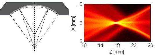
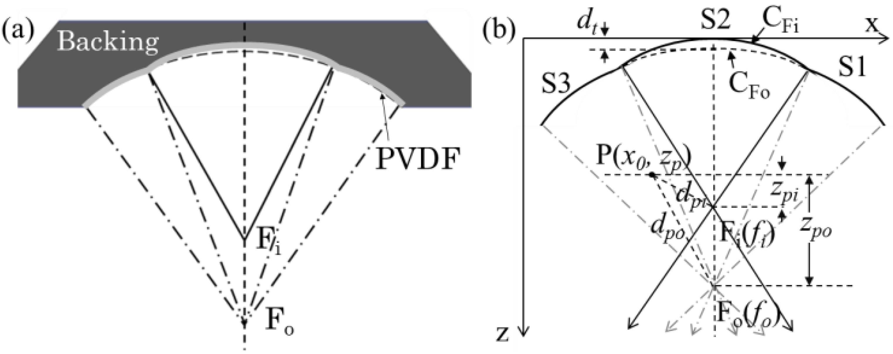
In this study, we designed and fabricated 1-D line-focusing transducers with PVDF film. Although a PVDF transducer has a lower sensitivity (23 × 10−12 C/N in Piezo Strain Constant, and 12% of Electromechanical Coupling Factor) than piezoelectric ceramics (PZT, 110 × 10−12 C/N in Piezo Strain Constant, and 30% of Electromechanical Coupling Factor) based transducers, it has the unique merit of flexibility, allowing it to be easily fabricated in arbitrary shapes [12]. Figure 1a depicts the design of a single element-based dual focused transducer. It was fabricated based on a shaped backing base which had two foci in the converging direction, and . A PVDF film was placed against the backing material perpendicular to the focusing direction. The dual- or single-focused transducer was produced according to the shape of the PVDF film.
For dual-focused PAM imaging, although it is a single transducer element, the detected A-line signal at each scanning position is actually the integration of three sections of the PVDF film, which are S1, S2 and S3, as shown in Figure 1b. To correctly recover the PAM image, we must employ a reconstruction method to extract the depth information from the integrated signal. To achieve this signal extraction, we developed a synthetic aperture dual focusing technique (SADFT) to reconstruct PAM image according to the actual transducer shape. The reconstruction method of SADFT is based on the fact of dual foci, as illustrated in Figure 1b where and are two foci for a dual focused transducer, representing the focus of section S2 and the common focus of sections S1 and S3, respectively. For a target point , it will be covered consequently by the three sections during the scanning process.
Figure 1.
(a) Schematic of single element-based dual focused transducer; (b) Illustration of and synthetic aperture dual focusing technique (SADFT).
Figure 1.
(a) Schematic of single element-based dual focused transducer; (b) Illustration of and synthetic aperture dual focusing technique (SADFT).
When the point is located in the acoustic detection field of sections S1 and S3 (the area within light color dot-dashed lines), the detected signal should contribute to the lower focus () reconstruction and the relative time delay can be expressed as:
where, is the depth of point P; is the focal length of the outer sections S1 and S3; is the distance from point P to focal point ; is the depth from point P to focal point ; and c is the acoustic velocity.
Summing the adjacent delayed signals, we obtained the processed result detected by sections S1 and S3,
where, is the received signal at the A-line; is the number of A-line when the point P located in the detection area of sections S1 and S3 (outer section).
Similarly, we can obtain the processed result detected by section S2,
where, is the received signal at the A-line; is the number of A-line when the point P located in the detection area of section S2 (inner section); and is the depth of point P; is the focal length of section S2; is the distance from point P to focal point ; is the depth from point P to focal point ; and c is the acoustic velocity.
We noted that the dual foci with two different focal lengths are formed by the 3 arcs (i.e., S1, S2 and S3). Also, the boundaries of the two circles centered at () and () are not overlapped at the most top point. As shown in Figure 1b, there is a vertical distance between the points of and . Therefore, Equation (1) for outer sections (S1 and S2) is modified according to this distance as follows,
where, is the distance between the top points of and .
Besides, to further improve the focusing quality, a coherence factor [13] at each reconstruction point was employed as the weighting factor for each section. Since the outer sections S1 and S3 have same property, the weighting factors can be written as,
Then, by summing the three sections results and multiplied with the weighting factors, respectively, the SADFT result for dual-focused PAM can be written as,
where, is the acquired PA signal at the A-line.
3. Results
We employed a 52 thickness PVDF film (width: 2 mm) to fabricate the dual-focused and single-focused transducers which had a center frequency of 18.7 MHz with a bandwidth of 67.4%. The dual-focused transducer had a designed inner focal length of 18 mm and outer focal length of 20 mm with an “aperture diameter” of 20.4 mm; the single-focused transducer had a designed focal length of 18 mm with an “aperture diameter” of 18.5 mm.
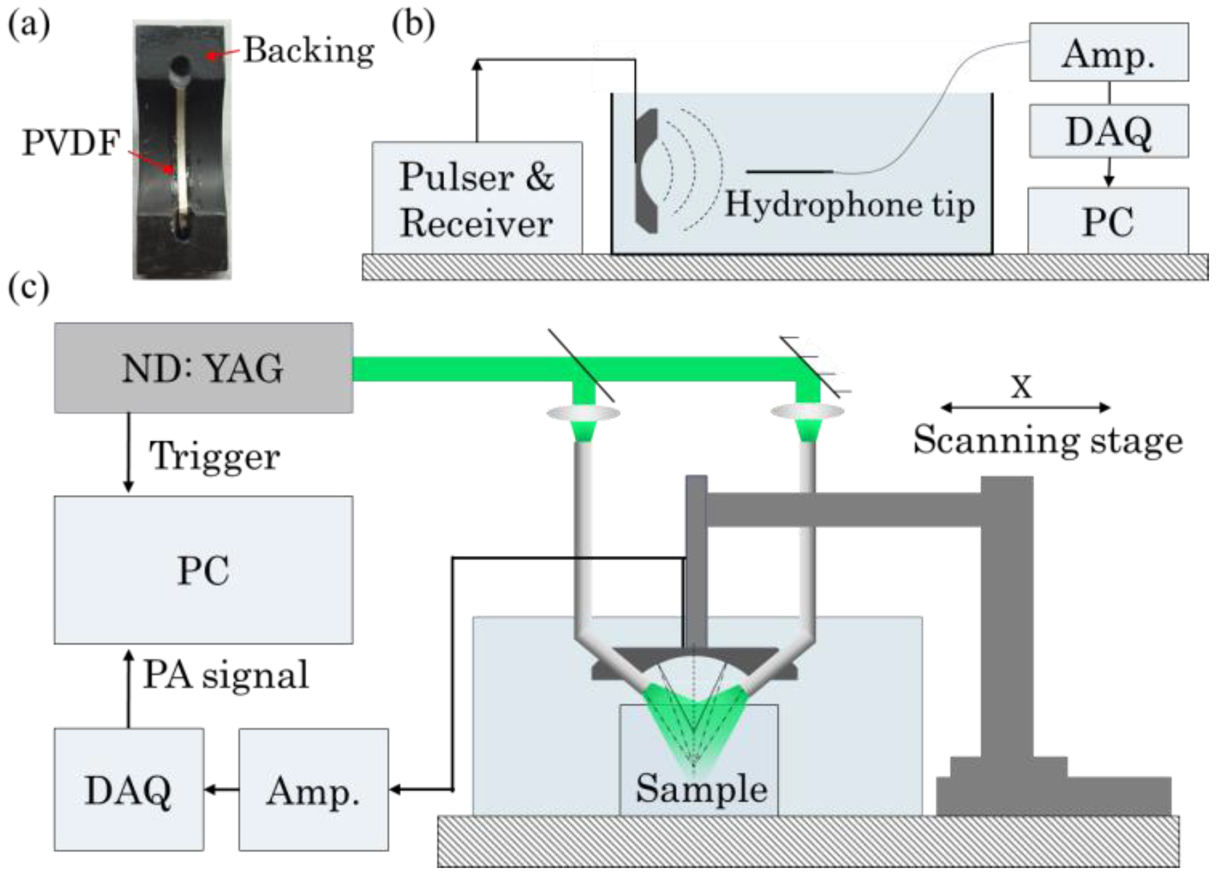
Figure 2a shows the photograph of the fabricated 1-D-focusing dual-focused transducer. Figure 2b is a schematic diagram of the experimental setup used to measure the ultrasound field distribution of transducers. A 200 m-diameter hydrophone (ONDA Inc.) was used to measure the ultrasound field distribution of the PVDF transducer. A Pulser&Receiver device (Olympus Inc.) was used to stimulate the PVDF transducer to generate acoustic signal and trigger the DAQ system to acquire the signal detected by hydrophone. Figure 2c shows the experimental setup used for photoacoustic microscopy validation. Pulsed laser light generated by a ND: YAG laser (532 nm) was split into two beams which were coupled into two fiber bundles whose distal ends were placed through the backing material for PAM light illumination. A scanning stage controlled by a personal computer was scanned along the X-direction to obtain B-scan PAM images.
Figure 2.
(a) Photograph of dual-focused acoustic transducer. (b) Schematic of the transducer ultrasound field distribution measurement setup. (c) Schematic diagram of acoustic resolution photoacoustic microscopy validation experimental setup.
Figure 2.
(a) Photograph of dual-focused acoustic transducer. (b) Schematic of the transducer ultrasound field distribution measurement setup. (c) Schematic diagram of acoustic resolution photoacoustic microscopy validation experimental setup.

The feasibility of single element-based dual focusing was demonstrated with numerical simulation using Ultrasim ultrasound simulation toolbox [14] and experimental measurements using the setup shown in Figure 2b. Ultrasound pressure field distribution map with two foci was observed from both simulated and measured results of dual focused transducer, as shown in Figure 3a. These results demonstrated the idea of single element-based dual focusing. However, due to the relatively low sensitivity of PVDF, the measured results were worse than the simulated, which featured with extended focal zones. It also has influence on the imaging results of the PAM experiments. Nonetheless, it is sufficient to demonstrate this innovative idea. In comparison, simulated and measured results of a single focused transducer were also presented in Figure 3b.
Figure 4 shows the experimental results of a phantom sample vertically embedded with 7 hairs. Figure 4a gives the photograph of the phantom sample where the depth from the top hair to the bottom one was measured to be 5.7 mm, and the background had a reduced scattering coefficient of 1/mm and an absorption coefficient of 0.007/mm. Figure 4b shows the B-scan PAM image obtained with the dual-focused transducer. Stronger signal is noted in the peripheral regions compared to that in the center area for deeply located targets, e.g., hairs 6 and 7, while such deeply located targets could not be well resolved with the conventional single-focused PAM [7,8]. The central section (S2) of the dual focused transducer had a shorter focal length (compared to S2 and S3) and mainly collected the PA signal from superficial layers, while the outer sections (S1 and S3) were able to be collect signal from the deeper layers.
Figure 3.
Ultrasound field distribution: (a) Simulated (top) and measured (bottom) distribution of a dual focused transducer; (b) Simulated (top) and measured (bottom) distribution of a single focused transducer.
Figure 3.
Ultrasound field distribution: (a) Simulated (top) and measured (bottom) distribution of a dual focused transducer; (b) Simulated (top) and measured (bottom) distribution of a single focused transducer.
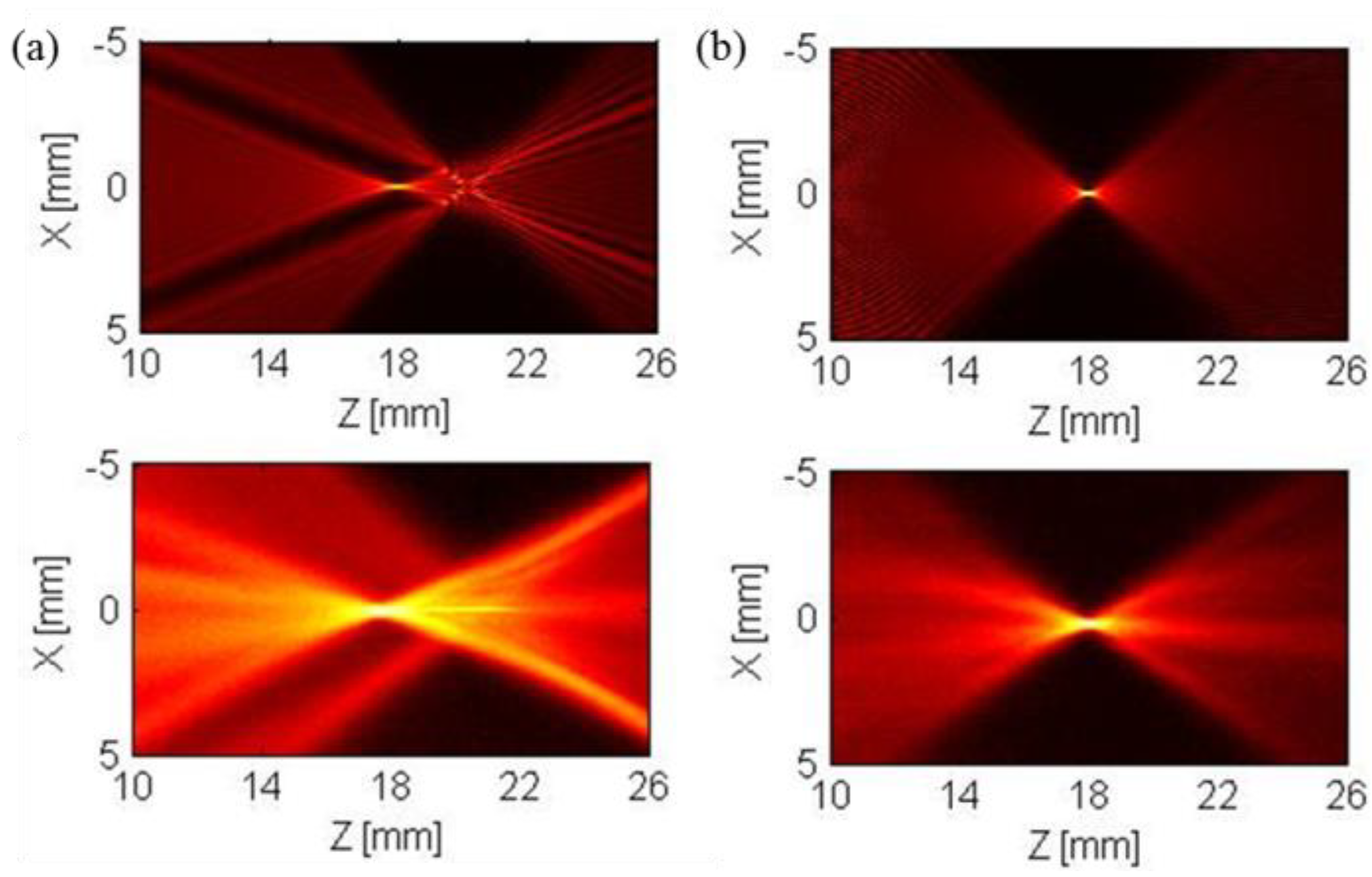
Figure 4.
Photoacoustic microscopy (PAM) experimental validation. (a) photograph of a phantom sample vertically embed with 7 hairs; (b) B-scan PAM image obtained with dual-focused transudcer and reconstructed directly from original data; (c) B-scan PAM image obtained with dual-focused transudcer and processed with SADFT; (d) B-scan PAM image obtained with single-focused transducer and processed with conventional SAFT; (e) comparison of transects’ profiles at the 2nd (DF FWHM=0.191 mm; SF FWHM = 0.124 mm) and 6th (DF FWHM= 0.148 mm; SF FWHM =0.251 mm)) hairs. DF: Dual Focused Transducer, SF: Single Focused Transducer.

The B-scan images obtained using dual-focused and single-focused transducers are further processed by SADFT and SAFT, and the results are shown in Figure 4c,d, respectively. Two focal regions can be observed from Figure 4c. The shorter focus is located near hair 2 and the longer one is near hair 6. The image quality, including SNR and lateral resolution, obtained by the single-focused transducer (Figure 4d) deteriorates significantly in the out-of-focus region (hairs 5, 6 and 7) compared to that with the dual-focused transducer (Figure 4c). Figure 4e compares the profiles of hair 2 and hair 6 obtained by the dual-focused and single-focused transducers. Since the transducer aperture of the inner section (S2) of the dual-focused transducer (~11 mm) is smaller than that of the single-focused transducer (~18.5 mm), the measured full width at half maximum (FWHM) for the superficially located hair 2 (H2) obtained by dual-focused PAM (0.191 mm) is worse than that obtained by single-focused PAM (0.124 mm). However, the measured FWHM for the deeply located hair 6 (H6) obtained by dual-focused PAM (0.148 mm) is about 2X better than that obtained by single-focused PAM (0.251 mm). In addition, the SNR for hair 6 obtained by dual-focused PAM is about twice higher than that by single-focused PAM.
4. Conclusion
We have described a SADFT reconstruction method based dual focused PAM and demonstrated its advantages over conventional single focused PAM. With this technique, stronger signal-to-noise ratio and higher lateral resolution are achieved in the conventional out-of-focus region. However, the current design has several limitations that need to be addressed in the future. First, due to a smaller numeric aperture (NA) of the center focusing element, the dual focused PAM has a lower lateral resolution than the single focused PAM in the shorter focusing region. This can be overcome by improving the aperture size. Second, there is a focusing gap between the two foci which resulted in low signal intensities in this region (hair 3, 4 and 5). To solve this problem, a parabolic shaped transducer with long continuous focal zone could be a good option. Third, the coherence weighting factor-based SAFT processing method is based on the assumption that the generated photoacoustic signals have spherical wave-front, typically generated by sparse absorbers; while in practice, the specimen may contain dense absorbers such as blood vasculature. In this case, the coherence weighting factor-based SAFT may not work as well as in specimens containing sparse absorbers. Employing the adaptive synthetic-aperture focusing technique may address this problem [8]. Lastly, we have to mention that validation experiments were performed based on the homemade 1-D line-focusing PVDF transducers which suffered from low center frequency and their performance highly depended on the fabrication technique. The advantages would definitely be more significant if a dual focused spherical transducer based on PZT or other high performance transducer materials were used.
Acknowledgments
This research was supported by a DOD grant.
Author Contributions
J. Tang designed and developed the single element-based dual focused transducer and the SADFT technique, performed simulation and validation experiments and wrote the paper; H. Jiang directed this study and wrote the paper.
Conflict of Interest
The authors declare no conflict of interest.
References
- Maslov, K.; Stoica, G.; Wang, L.V. In vivo dark-field reflection-mode photoacoustic microscopy. Opt. Lett. 2005, 30, 625–627. [Google Scholar] [CrossRef] [PubMed]
- Song, C.; Xi, L.; Jiang, H. Acoustic lens with variable focal length for photoacoustic microscopy. J. Appl. Phys. 2013, 114, 194703. [Google Scholar]
- Zhao, C.; Tan, J.; Tang, J.; Liu, T.; Liu, J. Confocal simultaneous phase-shifting interferometry. Appl. Opt. 2011, 50, 655–661. [Google Scholar] [CrossRef] [PubMed]
- Dunn, A.K.; Wallace, V.P.; Coleno, M.; Berns, M.W.; Tromberg, B.J. Influence of optical properties on two-photon fluorescence imaging in turbid samples. Appl. Opt. 2000, 39, 1194–1201. [Google Scholar] [CrossRef] [PubMed]
- Liao, L.-D.; Lin, C.-T.; Shih, Y.-Y.I.; Duong, T.Q.; Lai, H.-Y.; Wang, P.-H.; Wu, R.; Tsang, S.; Chang, J.-Y.; Li, M.-L. Transcranial imaging of functional cerebral hemodynamic changes in single blood vessels using in vivo photoacoustic microscopy. J. Cereb. Blood Flow Metab. 2012, 32, 938–951. [Google Scholar] [CrossRef] [PubMed]
- Xi, L.; Zhou, L.; Jiang, H. C-scan photoacoustic microscopy for invivo imaging of Drosophila pupae. Appl. Phys. Lett. 2012, 101, 013702. [Google Scholar] [CrossRef]
- Li, M.-L.; Zhang, H.F.; Maslov, K.; Stoica, G.; Wang, L.V. Improved in vivo photoacoustic microscopy based on a virtual-detector concept. Opt. Lett. 2006, 31, 474–476. [Google Scholar] [CrossRef] [PubMed]
- Deng, Z.; Yang, X.; Gong, H.; Luo, Q. Adaptive synthetic-aperture focusing technique for microvasculature imaging using photoacoustic microscopy. Opt. Express 2012, 20, 7555–7563. [Google Scholar] [CrossRef] [PubMed]
- Lu, H.; Shao, P.; Ranasinghesagara, J.; DeWolf, T.; Harrison, T.; Gibson, W.; Zemp, R.J. Improved depth-of-field photoacoustic microscopy with a custom high-frequency annular array transducer. SPIE Proc. 2011. [Google Scholar] [CrossRef]
- Gratt, S.; Passler, K.; Nuster, R.; Paltauf, G. Photoacoustic section imaging with an integrating cylindrical detector. Biomed. Opt. Express 2011, 2, 2973–2981. [Google Scholar] [CrossRef] [PubMed]
- Kolkman, R.G.; Hondebrink, E.; Steenbergen, W.; Mul, F.F. In vivo photoacoustic imaging of blood vessels using an extreme-narrow aperture sensor. IEEE J. Sel. Top. Quant. Electron. 2003, 9, 343–346. [Google Scholar] [CrossRef]
- Xi, L.; Li, X.; Jiang, H. Variable-thickness multilayered polyvinylidene fluoride transducer with improved sensitivity and bandwidth for photoacoustic imaging. Appl. Phys. Lett. 2012, 101, 173702. [Google Scholar] [CrossRef]
- Liao, C.-K.; Li, M.-L.; Li, P.-C. Optoacoustic imaging with synthetic aperture focusing and coherence weighting. Opt. Lett. 2004, 29, 2506–2508. [Google Scholar] [CrossRef] [PubMed]
- Holm, S. Ultrasim-a toolbox for ultrasound field simulation. In Proceedings of the Nordic Matlab Conference, Oslo, Norway, 17–18 October 2001.
© 2015 by the authors; licensee MDPI, Basel, Switzerland. This article is an open access article distributed under the terms and conditions of the Creative Commons Attribution license (http://creativecommons.org/licenses/by/4.0/).
Share and Cite
MDPI and ACS Style
Tang, J.; Jiang, H. Single Element-Based Dual Focused Photoacoustic Microscopy. Photonics 2015, 2, 156-163. https://doi.org/10.3390/photonics2010156
AMA Style
Tang J, Jiang H. Single Element-Based Dual Focused Photoacoustic Microscopy. Photonics. 2015; 2(1):156-163. https://doi.org/10.3390/photonics2010156
Chicago/Turabian StyleTang, Jianbo, and Huabei Jiang. 2015. "Single Element-Based Dual Focused Photoacoustic Microscopy" Photonics 2, no. 1: 156-163. https://doi.org/10.3390/photonics2010156