An Optimal Adaptive Constellation Design Utilizing an Autoencoder-Based Geometric Shaping Model Framework


1
Key Laboratory for Information Science of Electromagnetic Waves (MoE), Fudan University, Shanghai 200433, China
2
Shanghai Engineering Research Center of Low-Earth-Orbit Satellite Communication and Applications, Shanghai 200433, China
3
Shanghai Collaborative Innovation Center of Low-Earth-Orbit Satellite Communication Technology, Shanghai 200433, China
*
Author to whom correspondence should be addressed.
Photonics 2023, 10(7), 809; https://doi.org/10.3390/photonics10070809
Submission received: 20 June 2023
/
Revised: 7 July 2023
/
Accepted: 11 July 2023
/
Published: 12 July 2023
(This article belongs to the Special Issue Visible Light Communications)
Abstract
:Since visible-light communication (VLC) has become an increasingly promising candidate for 6G, the field of underwater visible-light communication (UVLC) has also garnered significant attention. However, the impairments introduced by practical systems and the time-varying underwater channels always limit the performance of underwater visible-light communication. In this paper, we propose and experimentally demonstrate an autoencoder-based geometric shaping model (AEGSM) framework to jointly optimize quadrature amplitude modulation (QAM) signals at the symbol-wise and bit-wise levels for underwater visible-light communication. Unlike traditional geometric shaping (GS) methods, which only give theoretically optimal shaping solutions, our framework can always obtain the globally optimal shaping scheme for a specific channel condition or different application scenarios. In our AEGSM framework, an autoencoder is used to find the optimal shaping scheme at the symbol-wise level and a revised pairwise optimization (RPO) algorithm is applied to achieve bit-wise optimization. In a real UVLC system, 2.05 Gbps transmission is achieved under the hard decision–forward error correction (HD-FEC) threshold of 3.8 × 10⁻³ by employing the autoencoder-based 8QAM (AE-8QAM) optimized by the AEGSM, which is 103 Mbps faster than the Norm-8QAM. The AE-8QAM also shows its resistance to nonlinearity and enables the UVLC system to operate within a larger dynamic range of driving voltages. The results substantiate the potential and practicality of the proposed AEGSM framework in the realm of underwater visible-light communication.
1. Introduction
In recent years, visible-light communication (VLC) has become an increasingly promising candidate for next-generation communications (6G) [1,2]. As a short-range optical wireless communication technology, VLC uses the intensity modulation of visible light to send data in the ultra-high frequency band. Compared with conventional wireless communication systems, VLC has many advantages, including high efficiency and anti-electromagnetic interference and being energy-saving and authorization-free [2,3,4]. With the continuous development of visible-light technology, VLC is becoming a popular research topic for specific communication scenarios, such as intersatellite communication and underwater visible-light communication (UVLC) [5,6].
Underwater visible-light communication (UVLC), which mainly uses blue and green light to transmit information in water with relatively low attenuation, can be classified as a light-emitting diode (LED)-based [7] and laser diode (LD)-based [8] system. The modulation bandwidth of LD is generally larger than that of LED, but the divergence angle of LD is relatively small, so strict alignment is required in LD-based visible-light communication systems [9]. Therefore, LED-based underwater VLC systems are more suitable for application scenarios involving mobile autonomous underwater vehicles and remotely operated underwater vehicles due to their wide lighting area coverage [10]. However, in the real LED-UVLC system, the modulation bandwidth of LEDs [11,12] is limited and the optoelectronic device has a nonlinear response, resulting in severe inter-symbol interference (ISI) and nonlinear interference for the transmitted signal [13]. In order to combat the nonlinear effects and limited bandwidth of the system and achieve high-speed information transmission, it is necessary to employ appropriate modulation formats and efficient digital signal processing methods to increase the transmission capacity of the system.
In general, spectrum-efficient modulation formats, such as quadrature amplitude modulation–discrete multitone modulation (QAM-DMT) and carrierless amplitude and phase modulation (CAP), are widely used to reach a high transmission data rate [14]. A large-coverage underwater single-input multiple-output VLC system over 1.2 m based on blue LED chips and 2 × 2 PIN arrays, using quadrature amplitude modulation–discrete multitone modulation (QAM-DMT), achieved a data transmission rate of 1.8 Gbps [15]. Recently, a transmission rate of 2.85 Gbps was achieved using 64QAM-carrierless amplitude and phase (CAP) modulation based on the constellation division scheme and blue LED [16].
It is worth noting that the constellation distribution schemes in QAM modulation formats currently used in underwater visible-light communication are mostly fixed and not adaptable, which makes it difficult to achieve an optimal performance for visible-light transmission based on norm QAM modulation under certain channel conditions. The design and optimization of constellations for specific channels is always a challenge. Geometric shaping (GS), probabilistic shaping (PS), and their combination have greatly advanced the development of constellation design [17,18,19]. To find better constellation schemes, an improved pairwise optimization (PO) algorithm was proposed to design a multi-dimensional constellation, which is based on minimizing the analytical BER of given M constellation points and bit mapping [20]. However, the constellation design generated by the PO algorithm is always based on prior theoretical knowledge, which cannot guarantee optimal performance in practical systems due to nonlinearity or other impairments. In other words, there is always a gap between the performance of current shaping schemes based on theoretical models and the optimal performance of real systems. Thus, designing a constellation-shaping scheme that is adaptive and closer to the specific real system is a critical issue in LED-based VLC systems.
With the development of deep learning, the concept of end-to-end communication was proposed to coordinate the optimization between transmitter and receiver in the traditional communication model, which is considered as a communication method that achieves global optima [21]. Based on end-to-end communication, novel autoencoder-based learning of joint geometric and probabilistic constellation shaping for coded modulation systems was proposed [22]. Geometrically shaped multi-dimensional modulation formats are designed via deep learning methods [23], and an end-to-end-based multi-dimensional GS strategy is proposed to achieve phase noise robustness [24]. Additionally, a differentiable GS method based on a blind phase search was also proposed for phase noise channels [25]. For visible-light communication, end-to-end communication based on an autoencoder has also gradually become a hot research topic. An autoencoder based on a data-driven channel model used to optimize end-to-end VLC systems has been proposed [10,26,27,28,29,30]. In [30], a deep-learning-based E2E VLCnet was suggested to realize flicker reduction and dimming operation. Since most previous studies have only been validated with a simulation experiment, in [29], an autoencoder was deployed in a real VLC system for the first time and successfully achieved a transmission rate of 1.875 Gbps under the 7% HD-FEC threshold. However, this work cannot further improve the transmission rate, because it discards almost all communication techniques and digital signal processing methods, only using two neural networks to send and receive data. How to combine autoencoder and digital signal processing algorithms to achieve jointly optimal communication performance is still a great challenge.
In this work, for the first time, we propose and experimentally demonstrate an autoencoder-based geometric shaping model (AEGSM) framework to jointly optimize quadrature amplitude modulation (QAM) signals at the symbol-wise and bit-wise levels for underwater visible-light communication. Unlike traditional GS methods, which only give theoretically optimal shaping solutions, our framework can always obtain the globally optimal shaping scheme for a specific channel or different application scenarios. Compared with the conventional autoencoder-based geometric shaping model or other geometric shaping methods, our framework realizes the effective combination of end-to-end learning and traditional geometric shaping theory so that the obtained constellation scheme can further guarantee optimal BER performance on the basis of ensuring optimal SER performance. And due to its adaptability, it is suitable for any channel condition or application scenario, bringing new inspiration to the other communication fields. In a real UVLC system, a 2.05 Gbps transmission is achieved under the hard decision–forward error correction (HD-FEC) threshold of by employing the autoencoder-based 8QAM (AE-8QAM) optimized by the AEGSM, which is 103 Mbps faster than the Norm-8QAM. The AE-8QAM also shows its resistance to nonlinearity and enables the UVLC system to operate within a larger dynamic range of driving voltages, extending it by 58.37%. The research results confirm the potential and great advantages of the proposed AEGSM framework in the field of underwater visible-light communication.
2. Principle
2.1. Overview of the Autoencoder-Based Geometric Shaping Model
The real underwater visible-light communication system design adopts a modular approach, and the entire communication system consists of multiple sub-modules, including source coding, channel coding, modulation, channel estimation, and channel equalization. Every model has to be as realistic as possible for an optimal performance. However, the traditional GS methods used in UVLC are based on a series of ideal model blocks, each of which is built based on a prior mathematical theory. This means the traditional GS methods can only work with ideal and static systems, and they cannot be optimal solutions for real UVLC systems. Using deep learning and autoencoder techniques, we can employ a neural network to model the entire visible-light communication system and use an autoencoder to automatically generate an initial shaping scheme to guarantee the best SER performance. In order to further ensure the optimal BER performance, a revised pairwise optimization (RPO) algorithm can be used to find the best bit representation for each constellation point to obtain a globally optimal shaping scheme. The principle of the autoencoder-based geometric shaping model (AEGSM) using end-to-end learning is shown in Figure 1.
As shown in Figure 1, the autoencoder-based geometric shaping model framework consists of three main modules, namely symbol-wise optimization, bit-wise optimization, and the UVLC test. The symbol-wise optimization module is divided into three steps: collecting symbol data, training the channel model, and training the autoencoder. In the first step, the data to be sent are first mapped by the Norm-8QAM to obtain the original constellation, and after up-sampling, IQ separation, and CAP modulation, it is sent to the arbitrary waveform generator to obtain the transmitted signal. At the receiving end, the signal passing through the actual underwater visible-light channel is subjected to corresponding CAP demodulation, down-sampling, and post-equalization processing to obtain the distorted constellation. After the distorted constellation is mapped to a symbol for performance testing, it is sent to the second step as the label of the channel model training, and the corresponding input is the original constellation obtained in the first step. In the stage of training the self-encoder, the channel model trained by the second step is embedded between the encoder and the decoder, and the weights are frozen to simulate the real underwater optical channel. The autoencoder performs unsupervised learning to find the optimal constellation distribution scheme at the symbol-wise level. In the bit-wise optimization module, the constellation distribution generated by the autoencoder is paired with the optimal bit representation under the optimization objective of the RPO algorithm. In the final step, the UVLC test module, the data to be sent are mapped by the AE-8QAM and processed by corresponding DSP methods, including up-sampling, IQ separation, and CAP modulation. After DA conversion, the processed signal is then input into the actual underwater visible-light communication system. At the receiving end, the received signal is first subjected to AD conversion and sequentially undergoes CAP demodulation, down-sampling, post-equalization, and AE-8QAM de-mapping for performance testing.
Firstly, to train the channel model based on the neural network, the signal to be sent is modulated by norm QAM-CAP and transmitted in the real underwater visible-light system. Then, we collect the constellation signals of the transmitting end and receiving end to use as the input and labels of the channel training, respectively, and conduct channel training. Next, we embed the trained channel model weights into the autoencoder and freeze the channel model. The autoencoder then undergoes unsupervised learning to generate a symbol-wise optimal reshaping scheme. In the second stage, driven by the optimization function of the pairwise optimization algorithm, we fix the constellation distribution generated by the autoencoder, and continuously adjust the bit mapping of the constellation symbols to achieve bit-wise optimization of the constellation scheme. After obtaining the jointly optimized shaping scheme, we deploy it in the real underwater visible-light system to replace norm quadrature amplitude modulation and map the data to be sent. At the receiving end, we use the corresponding constellation scheme to de-map the received signal after DSP processing to calculate the bit error rate and evaluate the performance.
2.2. Autoencoder-Based Symbol-Wise Optimization
During the symbol-wise optimization stage, we use an autoencoder to find the optimal constellation distribution to guarantee the best SER performance. Regarding the autoencoder, we regard the transmitting part of the communication system as an encoder, and the receiving part as a decoder, and what is transmitted in the channel is the constellation scheme learned by the encoder. In order to allow the gradient of the receiver network to backpropagate to the transmitter network, we need an additional channel neural network to model the real underwater visible-light channel and embed the channel model between the encoder and decoder, and finally a complete autoencoder for geometric shaping can be obtained. The neural network structure of the autoencoder is shown in Figure 2.
For encoders, their input is a one-hot vector, and the index of the non-zero position in the vector represents the symbol to be transmitted. To simulate the inter-symbol interference between consecutive samples introduced by the channel effect, multiple encoders are connected in parallel to represent different moments, and the results they produce represent the real transmitted constellation sequence. For the channel model, it is trained in advance to learn the channel response of the actual underwater visible-light channel and then embedded into the autoencoder to act as the actual channel. The constellation sequence output to the encoders is firstly concatenated by a flatten layer and is then fed into the network-based channel to simulate real transmission in the underwater visible-light channel. After passing through the channel network, the distorted constellation is directly decoded by the decoder. The decoding result of the decoder is backpropagated under the action of the loss function, and the encoder is prompted to generate a globally optimal constellation distribution to adapt to the actual underwater visible-light channel. Once the learning of the autoencoder is completed, it will have the ability to generate the symbol-wise optimal constellation scheme to ensure the best SER performance.
The training of the autoencoder is divided into two phases: neural-network-based channel training and transceiver training. During the neural-network-based channel training phase, we use a multilayer perceptron to emulate the UVLC channel response for constellations of QAM signals and connect the computation graph between the encoder and decoder for the gradient backpropagation. The transmission equation of the neural-network-based channel can be expressed as
where and represent the weight matrix and biases of the layer, is the rectified linear unit (ReLU) [31], is the input constellations of transmitted signals, and is the channel output constellations. In order to imitate the real time-varying UVLC channel, additive white Gaussian noise (AWGN) is added on the output constellation of the whole neural-network-based channel model. The loss function for training the channel model can be expressed as
where is the received constellations, and is the corresponding model output constellations. The constellations of Norm-8QAM signals before and after passing through the real underwater visible-light channel are used as the input and labels for the channel model training to approximate the complicated channel effect.
During the transceiver training phase, the neural-network-based channel needs to be frozen to simulate the real channel. The randomly transmitted symbol is transformed into an one-hot vector, , where the element is equal to 1. The encoder learns to find the constellation of the one-hot vector and send the constellation to the neural-network-based channel model while the decoder learns to de-map and reconstruct original information, , according to the constellation received from the channel model. The output of the decoder is a probability vector over the possible classes, where the largest probability term is trained to have the same index as the “1” term in the encoder’s corresponding one-hot input .
As we only take the randomly generated one-hot vector as the input and label, the training of the transceiver can be regarded as an unsupervised learning process. The modified stochastic gradient descent algorithm Adam [32] is employed to train the transceiver. In the training process, Adam uses the cross-entropy loss to calculate the gradient of the whole network and update the weights of the encoder and decoder.
In this case, the network of the transceiver will self-optimize to find the most suitable constellation distribution for real underwater visible-light channel transmission. The loss function of this training procedure can be expressed as
where and represent the elements of and , respectively.
2.3. RPO-Based Bit-Wise Optimization
Since the training of the autoencoder is at the symbol-wise level, the shaping scheme generated by the autoencoder will no longer conform to Gray coding. Although it can guarantee the lowest SER in transmission, it cannot guarantee the lowest BER. Thus, the pairwise optimization algorithm [20] is applied to optimize the shaping scheme generated by the autoencoder at the bit-wise level. We use a two-dimensional I/Q constellation with M equally likely symbols to encode bits, whose bit mapping is represented by . The Hamming distance is defined as the number of bits that differ between and . The upper bound of the analytical expression of the symbol error rate (SER) can be expressed as , where represents the Gaussian equation, represents the norm operation of the vector, and is the variance of the two-dimensional Gaussian noise. When converting the symbol error rate (SER) into the bit error rate (BER), the result obtained by using the Gaussian equation is the weight of the Hamming distance between symbols. Ultimately, the objective function of the revised pairwise optimization (RPO) algorithm for two-dimensional constellation can be expressed as
Driven by the objective function, by fixing all constellation points and continuously adjusting the bit mapping between any two symbols, we can achieve the bit-wise optimization of the constellation generated by the autoencoder and finally obtain the jointly optimized shaping scheme.
To evaluate the performance of the shaping scheme and demonstrate the effectiveness of the autoencoder-based geometric shaping model (AEGSM) framework, taking the eight-order symbols as an example, we deploy the autoencoder-based 8QAM (AE-8QAM) scheme generated by the AEGSM in the simulation system and the real system, respectively, and compare it with the Norm-8QAM scheme and the PO-8QAM scheme, which is generated entirely by the PO algorithm in detail.
3. Simulation and Results
In this section, we will provide the detailed parameters of the proposed AEGSM system and a comparison of the performances of the AE-8QAM, Norm-8QAM, and PO-8QAM in a simulation environment. The parameters of the autoencoder are summarized in Table 1. The neural-network-based channel model is optimized via stochastic gradient descent (SGD), and the training batch size is 256. The parameter N is selected upon the principle that should converge towards the optimal length of the channel memory. Through continuous experimentation and exploration, we determine N to be 12 to simulate the memory of the channel to the greatest extent. After completing the training of the channel model, we embed the channel model into the autoencoder and freeze its weights, and then use Adam to train the encoder and decoder weights in the autoencoder with a batch size of 128. When the training is completed, we use the RPO algorithm to optimize the shaping scheme generated by the autoencoder at the bit-wise level, and then we can obtain the AE-8QAM.
Two types of channels are used in our simulation experiments. The first type of channel is the additive white Gaussian noise (AWGN) channel, which can be expressed as
where and represent the input and output of the channel, and represents the white Gaussian noise.
The second type of channel is the simulated VLC (simu-VLC) channel, which contains frequency fading, additive noise, and nonlinear distortions. It can be expressed as
where represents the nonlinear effect of the LED light source, is the frequency, and is the negative exponential frequency fading of the UVLC channel. The function expression of can be described as
where represents the simulated driving voltages [33].
The performance of the Norm-8QAM and PO-8QAM severs as the baseline in the simulation. The transmitted signals are mapped by our AE-8QAM, and then after being CAP-modulated, they are sent to the simulation channel, and finally the received signals are demodulated and de-mapped to calculate the BER, and their performance is compared with baseline.
Figure 3 illustrates a comparison of BER performance versus different SNRs with different shaping schemes in the AWGN channel. We can see that in the case of an extremely low signal-to-noise ratio, none of the three shaping schemes can resist strong noise, so they all show extremely poor performance, and there is no obvious performance gap. Thus, the constellations of the three schemes in region (i) are all severely distorted. But with the improvement in the signal-to-noise ratio, the performance of the PO-8QAM and AE-8QAM gradually improves compared to that of the Norm-8QAM due to their self-adaptive ability. According to the constellations in region (ii) and region (iii), the AE-8QAM and PO-8QAM can be adaptively adjusted according to the channel signal-to-noise ratio to achieve a better performance. At this time, the PO-8QAM and AE-8QAM show almost the same performance, which means that the PO-8QAM can achieve an optimal transmission performance like the AE-8QAM under the ideal AWGN channel, in line with the theoretical model of the PO algorithm.
In the second type of simulation channel, the comparison of BER performance versus the estimated SNR of the entire channel with different shaping schemes is shown in Figure 4. It is worth noting that the signal-to-noise ratio at this time is estimated using the EVM algorithm [34]. Similarly, the three shaping schemes have poor performance at a very low SNR, and the constellations in region (i) also exhibit great distortion. Additionally, due to the addition of nonlinearity, the performance at this time is worse than that in the Gaussian white noise channel under the same SNR. The constellations in the three regions of Figure 4 are more severely distorted than those in Figure 3, and there are more obvious nonlinear distortions in the constellations. These distortions reflect the unique characteristics of the nonlinear simulation channel compared to the Gaussian channel. It is noted that as the SNR increases, both the AE-8QAM and PO-8QAM also show better performances than the Norm-8QAM, but at the same time, the AE-8QAM starts to perform better than the PO-8QAM. This means that the AE-8QAM has a stronger ability to resist nonlinearity and adaptive ability for specific channels.
We then test the BER of the three shaping schemes by adjusting the Vpp parameters of the simu-VLC channel. The signal-to-noise ratio of Gaussian white noise is fixed at 15dB. Figure 5 shows the BER versus simulated Vpp with different shaping schemes in the simu-VLC channel. As Vpp increases and the nonlinear effect of the system becomes more and more significant, the AE-8QAM achieves a significantly lower BER than the other two schemes. When the Vpp is too large and the nonlinear effect of the entire channel is very strong, the upper limit of the correct rate of transmission is limited, and the gain of the AE-8QAM compared with the PO-8QAM is not further improved. Owning to the lack of adaptability to different channel conditions, the Norm-8qm always presents the worst performance. Although the PO-8QAM has a certain adaptive ability, it only makes adjustments to the theoretical signal-to-noise ratio, and cannot consider the specific damage caused by the channel. Therefore, it will have a poorer performance than the AE-8QAM.
4. Experimental Setup
Figure 6 presents the experimental setup of an underwater VLC system with CAP modulation. At the transmitter end, the original data are mapped to 8QAM complex symbols. Then, the symbols are up-sampled with an up-sampling factor of 4. The complex up-sampled symbols are separated to in-phase (I) and quadrature (Q) and filtered by a pair of pulse-shaping filters. After this, the digital signal is converted to an analog signal using a 4.2 GSa/s arbitrary waveform generator (AWG, Tektronix AWG710B). The sampling rate of the AWG can be set according to specific experimental needs. The generated analog signal is first pre-equalized by a circuit [35] and amplified by a 1 GHz electrical amplifier (EA, Mini-Circuits ZHL-2-8-S+), and then it is coupled with a direct current using a 4.2 GHz bias tee (Mini-Circuits ZFBT-4R2GW-FT+) to drive a green silicon substrate LED. Before the LED, we use a lens to transmit parallel light to emit it into the water. The green light passes through a 1.2 m tank filled with water whose temperature is controlled at 25 degrees Celsius.
At the receiver end, another lens is used to focus light on a PIN (Hamamatsu S10784), which converts the optical signal to electrical signals. An iris diaphragm is placed between the lens and PIN to avoid receiver saturation. The electrical signal is then amplified by a pair of differential EAs and is sampled with a digital real-time oscilloscope (OSC, Agilent MSO9254A, Santa Rosa, CA, USA) at a sampling frequency of 2 GSa/s. The received digital signal is equalized by a wave-wise Volterra equalizer in the time domain and demodulated via CAP demodulation. Later, the signal is down-sampled and de-mapped after symbol-wise equalization. At last, we calculate the bit error ratio (BER) and compare the transmission performance among the AE-8QAM, Norm-8QAM, and PO-8QAM. The wavelength of the employed LED is 520 nm, and the −10dB bandwidth of the LED is 30 MHz. The bias current we use in the experiment is 258 mA and the power is 100 mW according to our measurements.
5. Experimental Results and Discussion
In this section, we compare the performance of the proposed AE-8QAM with the Norm-8QAM and PO-8QAM in the real UVLC system. Before starting the performance comparison, we first analyze the convergence of the neural-network-based channel model and autoencoder in our AEGSM framework. Figure 7 illustrates the learning curve for training loss and test loss of the channel model and autoencoder during symbol-wise optimization. We can see that the training and testing loss of the channel and autoencoder decrease quickly. In order to ensure that the training of the channel model and autoencoder can fully converge, we set the epoch of both of them to 100.
On the basis of training the AE, we further optimize the constellation distribution output by the encoder at the bit-wise level and then deploy it to the real system for performance testing. Figure 8 shows the BER performance of the Norm-8QAM, PO-8QAM, and AE-8QAM versus Vpp in a real UVLC system. Additionally, to verify the performance improvement brought about by bit-wise optimization, we also plot the BER performance of the AE-8QAM without the RPO algorithm simultaneously. As Vpp increases from a small value, the BER of all shaping schemes decreases until the optimal operating point is reached. When the Vpp is too large, the signal suffers from strong nonlinearity and is damaged seriously, so after the optimum point, the BER increases with Vpp. Figure 9 illustrates the constellation points of all shaping schemes received under different Vpp values, which shows that the signal will be greatly damaged if the Vpp is too large or too small. Compared with other shaping methods, the AE-8QAM has always achieved the best performance due to its strong adaptive ability and anti-nonlinearity. At the same time, the performance gap between the AE-8QAM without the RPO algorithm and the AE-8QAM verifies the gains brought about by bit-wise optimization.
Furthermore, to comprehensively explore the gains of different shaping schemes under various equalization algorithms, three different symbol-wise post-equalization algorithms are employed under the same experimental platform to perform symbol-wise post-equalization: LMS equalization, Volterra equalization, and NN-based equalization. Before performing symbol-level post-equalization, all received signals are processed with wave-wise Volterra equalization to obtain the optimal performance. The Q factors of different shaping schemes under different post-equalization procedures are shown in Figure 10. It is worth noting that the Q factor of the AE-8QAM after NN-based equalization is only increased by 0.30 dB compared with that after LMS post-equalization, which is lower than the Nom-8QAM’s 0.90 dB and PO-8QAM’s 0.46 dB. This also confirms that the AE-8QAM itself has a certain anti-nonlinear ability, so the gain of the AE-8QAM between using NN-based post-equalization and LMS post-equalization is not obvious. However, since the Norm-8QAM does not have an adaptive ability or anti-nonlinearity, there will be a more obvious performance improvement after using NN-based post-equalization than that seen when using LMS post-equalization.
After investigating the BER performance and Q factor gains, we fix the bias and amplitude of each shaping scheme to their optimal values and test their performance at different transmission rates. Figure 11 represents the performance of the three schemes under different bit rates, in which we can find a 103 Mbps improvement of the AE-8QAM compared with the Norm-8QAM at the 7% HD-FEC threshold. The AE-8QAM optimized by our AEGSM framework achieves highest transmission speed of 2.05 Gbps in the real UVLC system. Throughout the experiment, the roll-off factor of the shaping filter is set to 0.205. The carrier frequency is 407 MHz, and the bandwidth is 801 MHz when the transmission rate achieves 2G. The spectrum of the corresponding transmitted signal at this time is shown is on the right side of Figure 11. The parameters used in the digital signal processing in the experiment are shown in Table 2.
6. Conclusions
In this work, an autoencoder-based geometric shaping model framework is proposed to jointly optimize QAM signals at the symbol-wise and bit-wise levels for underwater visible-light communication with a green LED using CAP modulation. Traditional shaping methods always give shaping schemes based on theoretical models, which do not consider the specific characteristics of the actual transmission channel, resulting in errors caused by the discrepancy between theory and reality. To solve this problem, we use a neural-network-based model to model the entire underwater visible-light communication channel and use an autoencoder to automatically generate a symbol-wise globally optimal shaping scheme. A revised pairwise optimization (RPO) algorithm is then used for bit-wise optimization. In the experiment, a 2.05 Gbps transmission can be achieved under the 7% HD-FEC threshold by employing the autoencoder-based 8QAM (AE-8QAM) optimized by the AEGSM, which is 103 Mbps faster than the Norm-8QAM. Besides, the AE-8QAM enables the UVLC system to operate within a larger dynamic range of driving voltages, extending it by 58.37%, which demonstrates its ability to adapt to dynamic signals and different channel conditions. Such an auto-shaping framework can also bring new inspiration to other communication fields.
Author Contributions
Conceptualization, Y.W., L.Y., H.Z., C.S., N.C. and J.S.; methodology, Y.W., L.Y., H.Z. and J.S.; software, Y.W., L.Y. and H.Z.; validation, Y.W.; formal analysis, Y.W.; data curation, Y.W.; writing—original draft preparation, Y.W.; writing—review and editing, J.S.; visualization, Y.W.; supervision, J.S.; project administration, J.S.; funding acquisition, J.S. All authors have read and agreed to the published version of the manuscript.
Funding
This work was funded by the National Key Research and Development Program of China (2022YFB2802803), the National Natural Science Foundation of China Projects (No. 61925104, No. 62031011, and No. 62201157), the Major Key Project of PCL, the China Postdoctoral Science Foundation (2021M700025), and the China National Postdoctoral Program for Innovative Talents (BX2021082).
Institutional Review Board Statement
Not applicable.
Informed Consent Statement
Not applicable.
Data Availability Statement
The data that support the findings of this study are available from the corresponding author upon reasonable request.
Conflicts of Interest
The authors declare no conflict of interest.
References
- You, X.; Wang, C.-X.; Huang, J.; Gao, X.; Zhang, Z.; Wang, M.; Huang, Y.; Zhang, C.; Jiang, Y.; Wang, J.; et al. Towards 6G wireless communication networks: Vision, enabling technologies, and new paradigm shifts. Sci. China Inf. Sci. 2021, 64, 110301. [Google Scholar] [CrossRef]
- Chi, N.; Zhou, Y.; Wei, Y.; Hu, F. Visible light communication in 6G: Advances, challenges, and prospects. IEEE Veh. Technol. Mag. 2020, 15, 93–102. [Google Scholar] [CrossRef]
- Lee, H.; Lee, S.H.; Quek, T.Q.S.; Lee, I. Deep learning framework for wireless systems: Applications to optical wireless communications. IEEE Commun. Mag. 2019, 57, 35–41. [Google Scholar] [CrossRef] [Green Version]
- Grubor, J.; Randel, S.; Langer, K.-D.; Walewski, J.W. Broadband information broadcasting using led-based interior lighting. J. Light. Technol. 2008, 26, 3883–3892. [Google Scholar] [CrossRef] [Green Version]
- Chi, N.; Haas, H.; Kavehrad, M.; Little, T.; Huang, X.L. Visible light communications: Demand factors, benefits and opportunities [guest editorial]. IEEE Wirel. Commun. 2015, 22, 5–7. [Google Scholar] [CrossRef]
- Jovicic, A.; Li, J.; Richardson, T. Visible light communication: Opportunities, challenges and the path to market. IEEE Commun. Mag. 2013, 51, 26–32. [Google Scholar] [CrossRef]
- Chi, N.; Hu, F. Nonlinear adaptive filters for high-speed led based underwater visible light communication [invited]. Chin. Opt. Lett. 2019, 17, 69–75. [Google Scholar] [CrossRef]
- Wang, J.; Lu, C.; Li, S.; Xu, Z. 100 m/500 Mbps underwater optical wireless communication using an NRZ-OOK modulated 520 nm laser diode. Opt. Express 2019, 27, 12171–12181. [Google Scholar] [CrossRef] [PubMed]
- Chen, H.; Jia, J.; Niu, W.; Zhao, Y.; Chi, N. Hybrid frequency domain aided temporal convolutional neural network with low network complexity utilized in UVLC system. Opt. Express 2021, 29, 3296–3308. [Google Scholar] [CrossRef] [PubMed]
- Shi, J.; Niu, W.; Li, Z.; Shen, C.; Zhang, J.; Yu, S.; Chi, N. Optimal adaptive waveform design utilizing an end-to-end learning-based pre-equalization neural network in an UVLC system. J. Light. Technol. 2023, 41, 1626–1636. [Google Scholar] [CrossRef]
- Hu, F.; Chen, S.; Li, G.; Zou, P.; Zhang, J.; Hu, J.; Zhang, J.; He, Z.; Yu, S.; Jiang, F.; et al. Si-substrate LEDs with multiple superlattice interlayers for beyond 24 Gbps visible light communication. Photonics Res. 2021, 9, 1581–1591. [Google Scholar] [CrossRef]
- Chi, N.; Zhang, M.; Shi, J.; Zhao, Y. Spectrally efficient multi-band visible light communication system based on nyquist pam-8 modulation. Photonics Res. 2017, 5, 588–597. [Google Scholar] [CrossRef]
- Elgala, H.; Mesleh, R.; Haas, H. An led model for intensity-modulated optical communication systems. IEEE Photonics Technol. Lett. 2010, 22, 835–837. [Google Scholar] [CrossRef]
- Chi, N.; Shi, M. Advanced modulation formats for underwater visible light communications invited. Chin. Opt. Lett. 2018, 16. [Google Scholar]
- Li, J.; Wang, F.; Zhao, M.; Jiang, F.; Chi, N. Large-coverage underwater visible light communication system based on blue led employing equal gain combining with integrated pin array reception. Appl. Opt. 2019, 58, 383–388. [Google Scholar] [CrossRef]
- Chen, H.; Niu, W.; Zhao, Y.; Zhang, J.; Chi, N.; Li, Z. Adaptive deep-learning equalizer based on constellation partitioning scheme with reduced computational complexity in UVLC system. Opt. Express 2021, 29, 21773–21782. [Google Scholar] [CrossRef] [PubMed]
- Vassilieva, O.; Kim, I.; Irie, H.; Koganei, Y.; Nakashima, H.; Akiyama, Y.; Hoshida, T.; Palacharla, P. Probabilistic vs. Geometric Constellation Shaping in Commercial Applications. In Proceedings of the 2022 Optical Fiber Communications Conference and Exhibition (OFC), San Diego, CA, USA, 6–10 March 2022. [Google Scholar]
- Maneekut, R.; Beppu, S.; Takahashi, H.; Tsuritani, T. Hybrid probabilistic and geometric shaping for 64-qam optical fiber transmission with maximum aposterior probability detection. In Proceedings of the 25th Opto-Electronics and Communications Conference (OECC), Taipei, Taiwan, 4–8 October 2020. [Google Scholar]
- Kaneda, N.; Zhang, R.; Lefevre, Y.; Mahadevan, A.; van Veen, D.; Houtsma, V. First experimental demonstration of flexible rate pon beyond 100Gb/s with probabilistic and geometric shaping. In Proceedings of the Optical Fiber Communications Conference and Exhibition (OFC), San Francisco, CA, USA, 6–11 June 2021. [Google Scholar]
- Zhang, S.; Yaman, F.; Mateo, E.; Inoue, T.; Inada, Y. A generalized pairwise optimization for designing multi-dimensional modulation formats. In Proceedings of the Optical Fiber Communications Conference & Exhibition, Los Angeles, CA, USA, 19–23 March 2017. [Google Scholar]
- O’Shea, T.; Hoydis, J. An introduction to deep learning for the physical layer. IEEE Trans. Cogn. Commun. Netw. 2017, 3, 563–575. [Google Scholar] [CrossRef] [Green Version]
- Aref, V.; Chagnon, M. End-to-end learning of joint geometric and probabilistic constellation shaping. In Proceedings of the Optical Fiber Communications Conference and Exhibition (OFC), San Diego, CA, USA, 6–10 March 2022. [Google Scholar]
- Naka, A.; Komatsu, M. Geometrically shaped multi-dimensional modulation formats designed by deep learning. IEICE Commun. Express 2023, 12, 139–144. [Google Scholar] [CrossRef]
- Talreja, V.; Koike-Akino, T.; Wang, Y.; Millar, D.S.; Kojima, K.; Parsons, K. End-to-end deep learning for phase noise-robust multi-dimensional geometric shaping. In Proceedings of the European Conference on Optical Communications (ECOC), Brussels, Belgium, 6–10 December 2020. [Google Scholar]
- Rode, A.; Geiger, B.; Schmalen, L. Geometric constellation shaping for phase-noise channels using a differentiable blind phase search. In Proceedings of the Optical Fiber Communications Conference and Exhibition (OFC), San Diego, CA, USA, 6–10 March 2022. [Google Scholar]
- Hao, L.; Wang, D.; Cheng, W.; Li, J.; Ma, A. Performance enhancement of ACO-OFDM-based VLC systems using a hybrid autoencoder scheme. Opt. Commun. 2019, 442, 110–116. [Google Scholar] [CrossRef]
- Lee, H.; Lee, I.; Lee, S.H. Deep learning based transceiver design for multi-colored VLC systems. Opt. Express 2018, 26, 6222–6238. [Google Scholar] [CrossRef] [PubMed]
- Lee, H.; Lee, I.; Quek, T.Q.S.; Lee, S.H. Binary signaling design for visible light communication: A deep learning framework. Opt. Express 2018, 26, 18131–18142. [Google Scholar] [CrossRef] [PubMed]
- Li, Z.; Shi, J.; Zhao, Y.; Li, G.; Chen, J.; Zhang, J.; Chi, N. Deep learning based end-to-end visible light communication with an in-band channel modeling strategy. Opt. Express 2022, 30, 28905–28921. [Google Scholar] [CrossRef] [PubMed]
- Ulkar, M.G.; Baykas, T.; Pusane, A.E. VLCnet: Deep learning based end-to-end visible light communication system. J. Light. Technol. 2020, 38, 5937–5948. [Google Scholar] [CrossRef]
- Glorot, X.; Bordes, A.; Bengio, Y. Deep sparse rectifier neural networks. J. Mach. Learn. Res. 2011, 15, 315–323. [Google Scholar]
- Kingma, D.; Ba, J. Adam: A method for stochastic optimization. arXiv 2014, arXiv:1412.6980. [Google Scholar]
- Niu, W.; Chen, H.; Hu, F.; Shi, J.; Ha, Y.; Li, G.; He, Z.; Yu, S.; Chi, N. Neural-network-based nonlinear tomlinson-harashima precoding for bandwidth-limited underwater visible light communication. J. Light. Technol. 2022, 40, 2296–2306. [Google Scholar] [CrossRef]
- Shafik, R.A.; Rahman, M.S.; Islam, A.R. On the extended relationships among EVM, BER and SNR as performance metrics. In Proceedings of the International Conference on Electrical & Computer Engineering, Dhaka, Bangladesh, 19–21 December 2006. [Google Scholar]
- Huang, X.; Wang, Z.; Shi, J.; Wang, Y.; Chi, N. 1.6 Gbit/s phosphorescent white led based VLC transmission using a cascaded pre-equalization circuit and a differential outputs pin receiver. Opt. Express 2015, 23, 22034–22042. [Google Scholar] [CrossRef]
Figure 1.
Principle of the autoencoder-based geometric shaping model framework.

Figure 2.
Schematic of the neural network structure of the autoencoder.

Figure 3.
BER versus SNR with different shaping schemes in AWGN channel.

Figure 4.
BER versus SNR with different shaping schemes in simu-VLC channel.

Figure 5.
BER versus simulated Vpp with different shaping schemes in simu-VLC channel.

Figure 6.
Experimental setup of UVLC system with a green LED.

Figure 7.
Learning curve of the channel model and autoencoder.
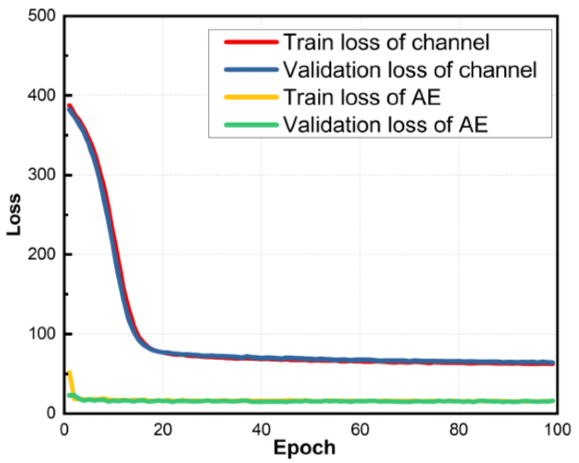
Figure 8.
BER performance of different shaping schemes versus Vpp in the real UVLC channel.

Figure 9.
Constellation after wave-wise Volterra equalization of a, b, and c in Figure 8.
Figure 9.
Constellation after wave-wise Volterra equalization of a, b, and c in Figure 8.

Figure 10.
Q factor of different shaping schemes with different equalization processing algorithms.

Figure 11.
BER performance versus bit rate with different shaping schemes.


Table 1.
Structure and parameters of the autoencoder.
| Type of Layer | Number of Neurons | Activation |
|---|---|---|
| Transmitters–Encoder | ||
| Input | 8 | None |
| Hidden Layer1 | 256 | ReLU |
| Hidden Layer2 | 256 | ReLU |
| Hidden Layer3 | 256 | ReLU |
| Output | 2 | None |
| Flatten | ||
| Neural-Network-Based Channel Model | ||
| Input | (2N + 1) × 2 | None |
| Hidden Layer1 | 66 × 2 | ReLU |
| Hidden Layer2 | 18 × 2 | ReLU |
| Output | 2 | None |
| Receiver–Decoder | ||
| Input | 2 | None |
| Hidden Layer1 | 256 | ReLU |
| Hidden Layer2 | 256 | ReLU |
| Hidden Layer3 | 256 | ReLU |
| Hidden Layer4 | 256 | ReLU |
| Output | 8 | Softmax |
Table 2.
Parameters for DSP processing.
| Up-Sampling Multiple | Roll-Off Factor | Bandwidth | Carrier Frequency |
|---|---|---|---|
| 4 | 0.205 | sampling rate 1/up-sampling multiple | sampling rate/up-sampling multiple × [(1 + roll-off factor) × 0.5 + 0.01] |
1 This is the sampling rate of AWG, which is set according to the specific transmission rate requirements.
Disclaimer/Publisher’s Note: The statements, opinions and data contained in all publications are solely those of the individual author(s) and contributor(s) and not of MDPI and/or the editor(s). MDPI and/or the editor(s) disclaim responsibility for any injury to people or property resulting from any ideas, methods, instructions or products referred to in the content. |
© 2023 by the authors. Licensee MDPI, Basel, Switzerland. This article is an open access article distributed under the terms and conditions of the Creative Commons Attribution (CC BY) license (https://creativecommons.org/licenses/by/4.0/).
Share and Cite
MDPI and ACS Style
Wei, Y.; Yao, L.; Zhang, H.; Shen, C.; Chi, N.; Shi, J. An Optimal Adaptive Constellation Design Utilizing an Autoencoder-Based Geometric Shaping Model Framework. Photonics 2023, 10, 809. https://doi.org/10.3390/photonics10070809
AMA Style
Wei Y, Yao L, Zhang H, Shen C, Chi N, Shi J. An Optimal Adaptive Constellation Design Utilizing an Autoencoder-Based Geometric Shaping Model Framework. Photonics. 2023; 10(7):809. https://doi.org/10.3390/photonics10070809
Chicago/Turabian StyleWei, Yuan, Li Yao, Haoyu Zhang, Chao Shen, Nan Chi, and Jianyang Shi. 2023. "An Optimal Adaptive Constellation Design Utilizing an Autoencoder-Based Geometric Shaping Model Framework" Photonics 10, no. 7: 809. https://doi.org/10.3390/photonics10070809
Note that from the first issue of 2016, this journal uses article numbers instead of page numbers. See further details here.