Review

Dispersive Fourier Transformation for Versatile Microwave Photonics Applications

School of Engineering and Digital Arts, University of Kent, Canterbury, Kent, CT2 7NT, UK
Photonics 2014, 1(4), 586-612; https://doi.org/10.3390/photonics1040586
Submission received: 15 November 2014 / Revised: 12 December 2014 / Accepted: 12 December 2014 / Published: 18 December 2014
(This article belongs to the Special Issue Microwave Photonics)

Abstract

:
Dispersive Fourier transformation (DFT) maps the broadband spectrum of an ultrashort optical pulse into a time stretched waveform with its intensity profile mirroring the spectrum using chromatic dispersion. Owing to its capability of continuous pulse-by-pulse spectroscopic measurement and manipulation, DFT has become an emerging technique for ultrafast signal generation and processing, and high-throughput real-time measurements, where the speed of traditional optical instruments falls short. In this paper, the principle and implementation methods of DFT are first introduced and the recent development in employing DFT technique for widespread microwave photonics applications are presented, with emphasis on real-time spectroscopy, microwave arbitrary waveform generation, and microwave spectrum sensing. Finally, possible future research directions for DFT-based microwave photonics techniques are discussed as well.

Graphical Abstract

1. Introduction

Microwave photonics (MWP) [1,2,3,4] is an emerging interdisciplinary area that investigates the interaction between microwave and optical waves, for widespread applications ranging from defense applications, such as radar [5,6] and electronic warfare systems [7], to civil applications, such as wireless [8,9] and satellite [10] communications, imaging [11] and instrumentation [12]. Thanks to inherent advantages of optics, such as high speed, broad bandwidth and reduced electromagnetic interference, various novel photonic techniques have been developed for efficient generation, distribution, control, processing and analysis of microwave signals [13], thus enhancing and enabling new functionalities that are very complex or challenging to achieve only in the microwave domain due to the limited speed and bandwidth of electronic devices. Recent research efforts within the area of microwave photonics include photonic generation [14] and processing [15,16] of microwave and millimeter-wave signals, photonically assisted phased array antennas [17,18], radio-over-fiber systems [19,20], arbitrary microwave waveform generation [21,22,23], and photonic analog-to-digital conversion (ADC) [24,25]. Most recently, integrated microwave photonics [26,27] has become an emergent topic aiming to reduce cost, power consumption, as well as to improve performance and robustness of MWP systems by incorporating discrete MWP components in photonic integrated circuits (PICs) [28,29,30].
Dispersive Fourier transformation (DFT) [31,32], also known as real-time Fourier transformation [33,34,35] or frequency-to-time mapping [36,37], uses large chromatic dispersion to map the spectrum of a broadband ultrashort optical pulse into a stretched time-domain waveform. With the help of high-speed time-domain modulation and detection technology, DFT enables ultrafast pulse-by-pulse spectroscopic measurement and manipulation. With this unique capability, DFT has become a powerful tool for high-throughput and real-time measurement where traditional instruments fall short [32,38].
DFT has also been widely employed in a diverse range of microwave photonics applications, such as microwave arbitrary waveform generation [23,39], microwave spectrum sensing [40,41], photonic ADC [24,42,43], real-time spectroscopy [44,45,46,47], optical sensor interrogation [48,49], and ultrafast continuous imaging [50,51]. In this paper, we review the recent development that we have made in this area. The paper is organized as follows. In Section 2, we introduce the theory and implementation of DFT. Its widespread applications in microwave photonics systems are discussed in Section 3, with emphasis on real-time spectroscopy, microwave arbitrary waveform generation, and microwave spectrum sensing. Finally, in Section 4, we outline the current limitations and potential future research directions for DFT-based microwave photonics applications.

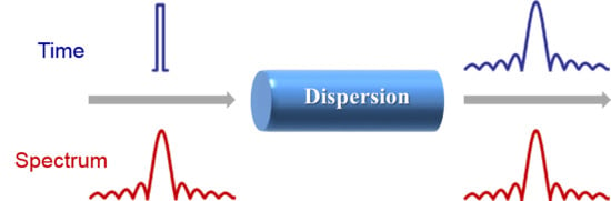
2. Dispersive Fourier Transformation Technique
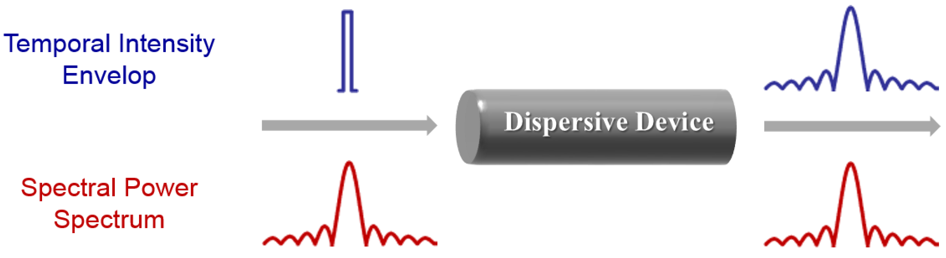
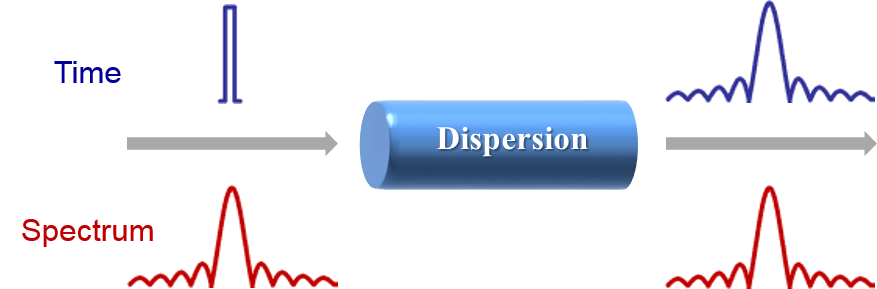
DFT is originated from the analogy between spatial Fraunhofer diffraction and temporal chromatic dispersion. It is known that a duality exists between the far-field diffraction of a beam of light from a thin lens and the propagation of a temporal pulse in a dispersive device under the second-order dispersion approximation [52,53]. The time-space duality shows that a dispersive element which provides distortion to a temporal signal in the time domain is the analogue of a free-space propagation in the space domain. The time-space duality has led to an interesting conclusion that if a transform-limited ultrashort optical pulse passes through a dispersive element, which should have sufficient chromatic dispersion to suffice the temporal far-field condition, the stretched optical pulse will have an intensity envelope that mimics the optical power spectrum of the original optical pulse. The concept of DFT can be understood intuitively by considering the dispersion stretching effect. The chromatic dispersion introduced causes a frequency-dependent linear time delay to the input optical pulse. Sufficient dispersion fully separates the spectral components of the input broadband optical pulse in time and realize the unique mapping from the frequency domain to the time domain. A schematic diagram of DFT is illustrated in Figure 1.
Figure 1. Schematic diagram illustrating dispersive Fourier transformation process in a dispersive device.
Photonics 01 00586 g001

2.1. Theory of DFT

2.1.1. Mathematical Description

It is known that a dispersive element can be modeled as a linear time-invariant (LTI) system with a transfer function given by H ( ω ) = | H ( ω ) | exp [ j Φ ( ω ) ] , where | H ( ω ) | and Φ ( ω ) are the magnitude and phase response of the dispersive element at angular frequency ω respectively. Mathematically, the phase response Φ ( ω ) can be expanded in Taylor series. Under the second-order dispersion approximation, in which the expanded phase terms higher than the second-order are ignored within the spectral bandwidth of interest, the transfer function and the corresponding impulse response of the dispersive element can be expressed as
H ( ω ) | H ( ω ) | exp ( j Φ 0 ) exp ( j Φ ˙ 0 ω ) exp ( j 1 2 Φ ¨ 0 ω 2 )
h ( t ) = F ˜ 1 [ H ( ω ) ] exp [ j 1 2 Φ ¨ 0 ( t Φ ˙ 0 ) 2 ]
where Φ ˙ 0 is the group delay and Φ ¨ 0 denotes the second-order dispersion, also known as group velocity dispersion (GVD).
Let x ( t ) and y ( t ) be the complex envelopes of the input and output optical pulses of a dispersion element with an impulse response h ( t ) , respectively. If the dispersion device has a wide bandwidth covering the whole spectrum of the input optical pulse, the output can be related to the input by the convolution operation, that is, y ( t ) = x ( t ) h ( t ) . Considering the impulse response in Equation (1b), we can rewrite the output pulse as
y ( t ) = + x ( t ) h ( t t ) d t + x ( t ) exp [ j 1 2 Φ ¨ 0 ( t t ) 2 ] d t     exp ( j t 2 2 Φ ¨ 0 ) + x ( t ) exp ( j 1 2 Φ ¨ 0 t 2 ) exp ( j 1 Φ ¨ 0 t t ) d t
here the constant time delay Φ ˙ 0 is ignored to allow us to focus on the pulse broadening induced by the dispersion. We assume the incident pulse has a limited pulse width of Δ t 0 . If the dispersion is sufficient such that | Φ ¨ 0 / ( Δ t 0 ) 2 | > > 1 , which is also known as the temporal Fraunhofer approximation, the stretched pulse can be further approximated by [34]
y ( t ) exp ( j t 2 2 Φ ¨ 0 ) + x ( t ) exp ( j t Φ ¨ 0 t ) d t     exp ( j t 2 2 Φ ¨ 0 ) X ( ω ) | ω = t Φ ¨ 0
where X ( ω ) = F ˜ [ x ( t ) ] is the Fourier transform of the input pulse. It is clearly shown in Equation (3) that the output temporal pulse envelope is proportional to the spectrum of the input pulse with a phase factor. Therefore, DFT or dispersion-induced frequency-to-time mapping is obtained.

2.1.2. Impact of Higher-Order Dispersion

Equation (3) provides the theoretical basis for the standard DFT, where the second-order dispersion approximation is applied. Therefore a unique linear one-to-one mapping between the optical frequency and time is created thanks to the linear group delay response with respect to the frequency. If higher-order dispersion is taken into account [54,55,56], the frequency-to-time mapping process is still valid so as long as the temporal Fraunhofer approximation is satisfied. In this scenario, however, the mapping is no longer linear due to the higher-order frequency dependency of the group delay. A modified nonlinear mapping relation incorporating higher-order dispersion is given [49]
ω = t Φ ¨ 0 k = 3 [ Φ k 0 ( k 1 ) ! ( Φ ¨ 0 ) k t k 1 ]
where Φ k 0 is the k-th order dispersion coefficient.

2.1.3. Near-Field Condition

In normal DFT process as outlined above, a significant amount of chromatic dispersion is required to satisfy the temporal far-field condition. The optical pulse that propagates through the dispersive medium will be fully stretched, making the time-encoded spectral features slowed down and easily captured in time-domain. However, highly dispersive media could cause significant signal losses, especially outside the telecommunication band. In addition, the substantial dispersion demand imposes a strong physical limit on the maximum update speed of DFT-based system and reduces the overall achievable time-bandwidth-product (TBWP) of the system.
Some research efforts have been dedicated to study relaxed dispersion requirement for far-field DFT [37] and its application in chirped microwave waveform generation [57]. A further study shows that even in the near-field region the spectral information can be reconstructed from two separate temporal measurements using off-line processing [58]. In [59], near-field DFT has been investigated for generating high fidelity microwave waveforms, which is made possible by pre-distorting the optical pulse before stretching.

2.2. Implementation of DFT

2.2.1. Optical Source

DFT is usually performed in the coherent regime and restricted to work with a Fourier transform-limited input ultrashort optical pulse only. A Fourier transform-limited pulse, or more commonly known as the transform-limited pulse, is usually an ultrashort optical pulse that has a constant phase (chirp free) across the whole pulse window and maintains the minimum possible time duration for a given spectral bandwidth. The amplitude spectrum of a transform-limited pulse is the Fourier transformation of its temporal envelope, which is, however, not valid for a non-transform-limited optical pulse with a time-dependent phase (chirp). Transform-limited optical pulses are usually generated by mode-locked lasers [60]. An alternative approach to generating transform-limited ultrashort optical pulses is based on electro-optic phase modulation of a continuous-wave laser and subsequent phase-to-intensity conversion and pulse compression in a dispersive medium [61,62]. Optical pulses generated by the latter method have a much higher repetition rate than that of mode-locked lasers, hence enabling higher update rate for real-time measurement. However, to avoid overlaps between consecutive stretched pulses, the effective time window will have to be significantly decreased.

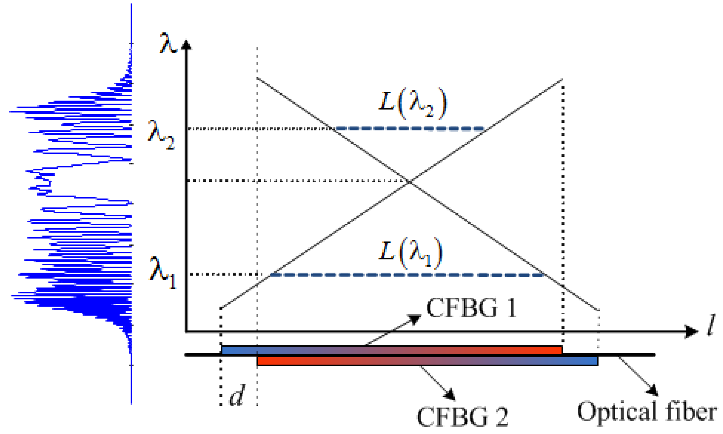
2.2.2. Dispersive Devices

Another essential requirement for implementing DFT is a dispersive device with sufficient and uniform chromatic dispersion to allow linear DFT process without distortion. The simplest and most commonly used dispersive element in DFT is standard single-mode fibers (SMF) [33,36,63]. SMF has a smooth dispersion curve for a broad optical bandwidth of more than 200 nm in the telecommunications band. The GVD coefficient is about 17 ps/nm/km at 1550 nm. To provide sufficient dispersion, a very long fiber is usually required, which makes the system bulky with high loss, and suffer from the higher-order dispersion and polarization mode dispersion [64]. Dispersion compensation fibers (DCF) offer a much larger chromatic dispersion (–120 ps/nm/km at 1550 nm) and have become a promising solution for DFT [45,65] thanks to its high dispersion-to-loss ratio. To further overcome propagation losses, distributed Raman amplification has been implemented simultaneously within the DCF, a process called amplified DFT [31]. Significant optical gain would enhance the sensitivity and resolution of DFT in high-throughput measurements [45]. However, one major difficulty is that no efficient DCFs are available outside the telecommunications band around 1550 nm.
The use of a linearly chirped fiber Bragg grating (LCFBG) provides a compact solution for implementing DFT [13,34]. A fiber Bragg grating (FBG) is basically a section of optical fiber where the refractive index of the fiber core is periodically modulated, normally via UV illumination [66]. Mode coupling between counter-propagation modes in the fiber core, which is induced by perturbation of refractive index, results in wavelength-dependent reflection. Thanks to the flexible spectral characteristics [67], all-fiber geometry, low insertion loss, compact size, and low cost, FBGs have been widely employed in microwave photonics applications [13,68,69]. In an LCFBG, different spectral components of an optical signal are reflected from different position of the grating due to the chirped grating period, making it a compact and broadband dispersive element with a large GVD. In addition, nonlinear optical effects are also reduced due to the short interaction length of the LCFBG. However, the main problem of the LCFBG for DFT is the group delay ripples (GDRs). The GDR is a result of the interference between the broadband reflection due to the edge of the grating and the distributed nature of the grating reflection [70] and may cause unwanted fast temporal modulations in the stretched pulses [71]. The GDR of an LCFBG can be significantly reduced by applying apodization during the fabrication process. However, an apodized LCFBG still exhibits pseudoperiodic GDRs due to the errors in grating period and the index modulation deviations resulting from imperfections in the fabrication process [72].
An alternative dispersive device exploits both spatial (angular) dispersion in a diffraction grating and the large modal dispersion [73] in a multimode waveguide. Such a chromo-modal dispersion (CMD) device has been successfully employed to achieve DFT for real-time absorption spectroscopy [74]. The CMD device offers large GVD in a huge spectral bandwidth where the multimode waveguide is transparent. Moreover, both amount and sign of the GVD can be easily tuned by changing the alignment conditions. However, since its group delay response has a nonlinear relation with respect to the optical wavelength, careful calibration and correction are required for linear DFT.

2.2.3. Operational Wavelength Bands of DFT

Most of DFT-based systems are designed to operate in the 1550 nm band, to take advantage of available high-quality dispersive devices, e.g., DCFs, and the low-cost photonic devices developed for fiber optic communications in this wavelength band. However, 1550 nm band has limited utility in biomedical and imaging applications due to its strong water absorption and poor spatial resolution. While shorter wavelengths are desirable for those applications, the main challenge is the lack of efficient dispersive device outside the 1550 nm band. Recent study has shown that DFT can be implemented at shorter wavelengths for biomedical applications [75,76].
Figure 2. Group delay response of the linearly chirped fiber Bragg grating (LCFBG) operating at 800 nm. One-to-one wavelength-to-time mapping verifies the Dispersive Fourier transformation (DFT) at 800 nm band [77].
Photonics 01 00586 g002
Particularly, the 800 nm wavelength band is useful for a broad range of industrial and biomedical applications, thanks to its large penetration depths in tissues, better spatial resolution, and the availability of powerful Ti:Sapphire lasers in this spectral band. While a small-core SMF provides sufficient GVD for DFT at 800 nm [51], the propagation loss is large and the amount of dispersion is limited. Moreover, a smaller fiber core easily causes unwanted nonlinear signal distortion. As a promising solution, an LCFBG operating at 800 nm band has been successfully employed for DFT in this application-rich spectral band [77]. The use of LCFBG features large GVD, low-loss, low cost, compact footprint and significantly reduced nonlinear optical effects. Figure 2 shows the group delay response of the LCFBG, which is evaluated by comparing the shaped pulse spectrum and the stretched temporal waveform. The GVD of the 30 cm-long LCFBG is as large as 840 ps/nm.

2.2.4. Incoherent DFT

Most of DFT operations are usually performed in the coherent regime using a transform-limited ultrashort optical pulse. Some recent work has explored the possibility of implementing DFT in the incoherent regime [78], using incoherent broadband optical sources, e.g., amplified spontaneous emission (ASE) radiation, where an external modulator is used to generate gated pulses. The potential of incoherent DFT in photonic microwave arbitrary waveform generation has also been studied [79]. Incoherent DFT may reduce the system cost, but at the price of a significantly higher noise added to the generated microwave waveform. This is because there is no phase correlation between the spectral components of an incoherent source. A full statistical study of the signal-to-noise ratio (SNR) of incoherent DFT process can be found in [80].

3. Microwave Photonics Applications of DFT

As it enables unique one-to-one mapping relation between frequency and time of a stretched broadband optical pulse, DFT has been widely applied in a variety of microwave photonics systems, for signal generation, measurement and processing applications. In this section, we discuss the recent development in employing DFT technique for various microwave photonics applications, such as real-time spectroscopy, microwave arbitrary waveform generation, microwave spectrum sensing, and photonic analog-to-digital conversion.

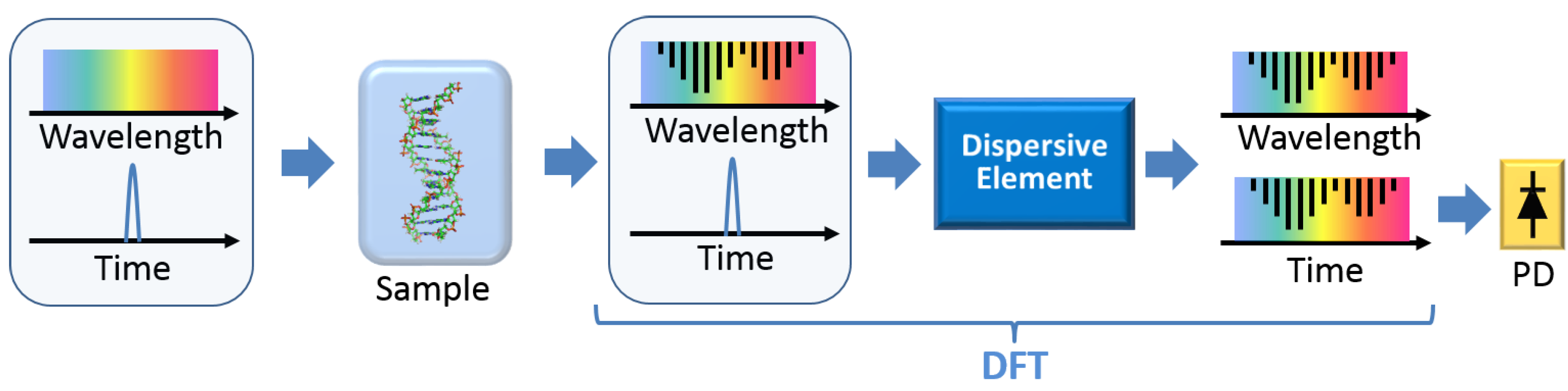
3.1. DFT for Real-Time Spectroscopy

Optical spectroscopy has been one of the most integral tools in scientific research, manufacturing, and medical applications. Ultrafast real-time spectroscopy is particularly useful for investigating rapid transient phenomena such as chemical reactions, phase transitions of thermodynamic systems, and protein dynamics in living cells. Unfortunately, conventional diffraction-grating-based spectrometers fall short in speed as they rely on either a moving mechanical part or a detector array with limited refresh rate.
Offering pulse-by-pulse spectrum monitoring, DFT’s most obvious application is real-time spectroscopy, which provides an indispensable solution for the challenging continuous ultrafast real-time optical spectrum measurement [44,45,46,47,81,82,83,84]. Figure 3 conceptually shows the DFT-based real-time spectroscopy, where the diffraction grating and detector array in conventional spectrometers are replaced by a dispersive element and a signal-pixel photodetector. The spectral features of the sample under test are first imprinted on the spectrum of the broadband optical pulse. After the DFT process, the spectral information is converted to a stretched temporal waveform. The converted temporal features usually fall into microwave frequency band and are slow enough to be captured by the high-speed PD and real-time digitizer, and then analyzed in digital domain. DFT-based real-time optical spectroscopy offers a scan rate of tens of MHz or even several GHz, determined by the repetition rate of the pulse train, which is more than three orders of magnitude higher than traditional spectrometers. The unique capability to capture single-shot spectra at high scan rates makes DFT spectroscopy an unprecedented tool for detecting non-stationary processes and rare events that would otherwise be lost in conventional time-averaged measurements [38]. Note that the overall spectral resolution of the DFT spectroscopy is determined by three factors: the temporal sampling rate of the electronic digitizer, the analog bandwidth of the photodetector, and the system dispersion [31].
Figure 3. Schematic diagram to show the real-time spectroscopy based on DFT. PD: photodetector.
Photonics 01 00586 g003
Being not limited to direct optical spectroscopy measurement, DFT technique can be also employed to perform a variety of high-throughput and real-time measurement that relies on spectral domain methods. One such an example is real-time interrogation of FBG sensors [48,49,85,86,87,88]. Most of the FBG sensors are functioning based on wavelength modulation, in which the sensed information is directly encoded as the grating wavelength (spectrum) change [89]. DFT technique maps the wavelength change to a temporal shift of the stretched waveform. This temporal-spectroscopy enables interrogation of FBG sensors in the megahertz regime [85], which is particularly useful for real-time diagnostics of fast-vibrating objects, such as a running aircraft engine. In addition, by applying pulse compression method in temporal-spectroscopy, both spectral resolution and signal-to-noise ratio of the FBG interrogation system can be improved [86,87]. This is made possible by pre-encoding a chirped profile onto the pulse spectrum before the pulse is sent to the FBG sensors. At the receiver end, a matched filter is employed to achieve pulse compression (auto-correlation).
Note that in the above DFT-based FBG sensor interrogation system, the measurement resolution is still limited by the temporal resolution of a commercial oscilloscope. While a larger dispersion would lead to a higher interrogation resolution since it converts a given wavelength shift to a longer temporal waveform shift, to avoid the temporal superposition of two adjacent stretched pulses, it also imposes a limit on the pulse repetition rate, equivalently the refresh rate of the measurement. To overcome the fundamental tradeoff between the interrogation speed and resolution, a new technique to achieve simultaneously ultrafast and ultrahigh-resolution interrogation of FBG sensors based on interferometric temporal spectroscopy has been proposed and experimentally demonstrated [48]. In the system, a reference FBG is introduced to produce a temporal interference pattern between two stretched waveforms reflected by the two FBGs. The temporal shift of the optical pulse can then be evaluated from the carrier frequency of the interference pattern, which is usually within microwave frequency range. Therefore, the interrogation resolution is greatly improved due to the facts that an interferometer has an inherently high sensitivity and that the equivalent resolution of an electrical spectrum analyzer is much higher than that of an oscilloscope. Moreover, since the generated interference pattern does not rely on the amount of dispersion, a high measurement speed is maintained, hence eliminating the above mentioned tradeoff.
Figure 4. An alternative real-time spectral interferometry system for complete pulse characterization based on unbalanced temporal pulse shaping (UB-TPS). PUT: pulse under test, DE: dispersive element, PD: photodetector. [65].
Photonics 01 00586 g004
DFT spectroscopy can also be employed in real-time characterization of optical pulses [65]. Ultrashort optical pulses with durations in the picosecond, femtosecond, and even attosecond regimes are powerful tools for studying fast dynamic phenomena in science and engineering. In such applications, fast, and complete (i.e., amplitude and phase) characterization of ultrashort pulses is essential for evaluation of optical systems that employ them. However, precise pulse measurement is challenging due to lack of fast enough photodetector to directly capture the ultrafast optical pulses. One widely used method is spectral phase interferometry for direct electric-field reconstruction (SPIDER) [90]. This technique relies on spectral interferometry measurement and its update rate is limited by the refresh rate of the optical spectrometer (typically up to ~ 10 kHz), hence not capable of real-time single-shot characterization of ultrashort optical pulses. A promising solution is real-time spectral interferometry [54,91], which combines SPIDER and DFT techniques, hence enabling pulse-by-pulse characterization of the complex field (amplitude and phase) with a significantly higher update rate of up to several GHz.
However, an optical interferometer is required to generate two time-delayed replicas of the original pulse for equivalent spectral shearing. This makes the system not stable due to the inherent high sensitivity of the interferometer to environmental perturbations. To remove this difficulty, in [54,91], an alternative real-time spectral interferometry method without using optical interferometers has been reported [65]. Figure 4 illustrates the principle of the method. An unbalanced temporal pulse shaping (UB-TPS) system [92] is used to simultaneously generate two time-delayed replicas of the input pulse under test and to implement DFT. The system is unbalanced as two dispersive elements (DEs) with opposite dispersion but nonidentical in magnitude are employed. As shown in Figure 4, the UB-TPS system is equivalent to a normal TPS system to perform a real-time Fourier transformation of the microwave driving signal for the generation of two time-delayed replica pulses, followed by a residual DE to stretch the pulses for the implementation of DFT. Therefore, the spectral interferometry can be implemented in the time domain based on DFT technique, enabling continuous single-shot characterization of ultrashort pulses at a high scan rate. More importantly, the system stability is greatly improved as no optical interferometers are needed anymore.

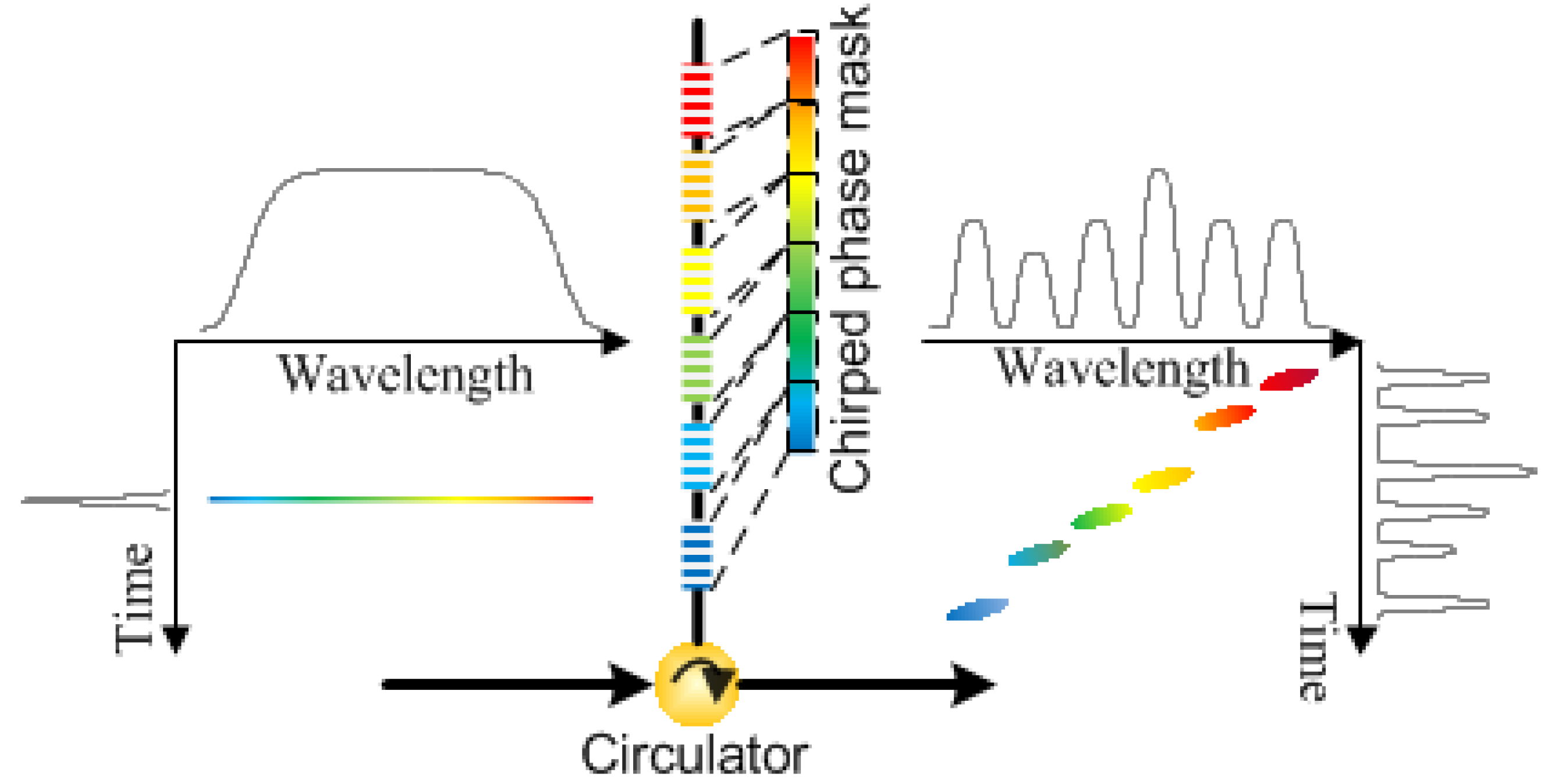
3.2. DFT for Microwave Arbitrary Waveform Generation

Microwave arbitrary waveforms have found wide applications in radar, wireless communications, imaging, and instrumentation systems. The difficulties of electrical method for generating microwave arbitrary waveforms include low frequency, small bandwidth and high cost, due to the limited sampling rate and analog bandwidth of electronic circuitry. Photonically assisted microwave arbitrary waveform generation (AWG) techniques provide the capability of generating high-frequency and broadband microwave arbitrary waveforms which may not be easily accomplished by conventional electronic techniques [23,93]. Various techniques, such as direct space-to-time (DST) pulse shaping [94,95], photonic microwave filtering [96,97], and DFT pulse shaping, have been proposed and demonstrated for photonic generation of microwave arbitrary waveforms. DST pulse shaping method splits a single optical pulse into a temporally distributed pulse sequence matching a spatially distributed pattern. Arbitrary envelope and phase profiles of the generated microwave waveform are determined by controlling the amplitude, pulse-to-pulse spacing and repetition rate of the pulse sequence. In photonic microwave filtering method, since the filter can be designed to have an arbitrary spectral response, the employment of the filter for the generation of an arbitrary microwave waveform can be realized.

3.2.1. General Concept

Among the various photonics-assisted approaches, DFT technique has also been extensively investigated for photonic generation of high-frequency and broadband microwave waveforms with arbitrary shapes. A schematic diagram showing the fundamental principle of the technique is illustrated in Figure 5. The system consist of an ultrashort pulsed source, a spectral filter and a dispersive element. The broadband optical pulse is first sent to an optical spectral filter with a properly designed spectral response. The spectrum-shaped optical pulse is then passing through a dispersive medium to undergo the dispersion-induced frequency-to-time mapping. A microwave waveform with an envelope identical to the shaped optical power spectrum is finally obtained at the output of a high-speed photodetector. A key feature of this technique is that the temporal pulse shaping is performed in the frequency-domain, which is easy to implement using an optical spectral filter.
Figure 5. Schematic diagram to show microwave arbitrary waveform generation based on spectral shaping and DFT. PD: photodetector.
Photonics 01 00586 g005
The key device in a DFT-based microwave arbitrary waveform generation system is the optical spectral shaper. A number of approaches for optical spectral shaping of an optical pulse have been proposed. For example, spectral shaping can be implemented in the spatial domain based on spatial masking of the spatially dispersed optical spectrum, where a spatial light modulator (SLM) is usually used to manipulate the input optical spectrum [98]. The key advantage of the SLM-based spatial domain optical spectral shaping techniques is that the filter response can be reconfigured in real time with the help of a computer [22,99]. Recently, a fully-programmable integrated optical spectral shaper fabricated on a silicon photonic integrate circuit has been demonstrated for microwave arbitrary waveform generation [100]. The spectral shaper is based on cascaded multi-channel microring resonators and response reconfigurability is achieved by thermal tuning using micro-heaters. These techniques, however, suffer from the difficulties such as complex alignment with strict tolerances, high cost and high coupling loss between free-space/waveguide optics and fiber optics. One solution is to use all-fiber optical spectral filters, which have the advantages of alignment free, simpler structure, better stability, lower loss and cost, and inherently good compatibility with other fiber-optics devices. In addition, an all-fiber system has high potential for integration. As a unique in-fiber device, FBG has been widely applied in optical spectral shaping as both the magnitude response and the phase response of an FBG can be precisely designed for complex spectral filtering [13].

3.2.2. All-Fiber DFT-Based Microwave AWG

Various configurations for all-fiber spectral shaping have been proposed for photonic generation of microwave arbitrary waveforms. For example, ultra-wide band (UWB) pulse generation based on spectral shaping using two uniform FBGs with one in transmission and the other in reflection, and DFT in a length of dispersive fiber has been recently demonstrated [36]. The optical fiber does not only serve as the dispersive element to accomplish the DFT-enabled wavelength-to-time mapping, but also as the optical link to distribute the UWB pulse to a remote site. UWB pulses have found wide applications in short-range high-data-rate wireless communications [101].
Chirped microwave pulses, due to their large time-bandwidth product (TBWP), have been widely used in modern radar systems to significantly improve the range resolution. Based on the DFT technique, a few methods have been reported to generate chirped microwave waveforms [102]. The main effort in DFT-based approach is to design an optical spectral shaper with its magnitude response having a chirped oscillating response with a varying free-spectral range (FSR). One design of such an optical spectral shaper is based on superimposing two chirped fiber Bragg gratings with different chirp rates into a same fiber with a small longitudinal offset [103]. As illustrated in Figure 6, a distributed Fabry-Perot cavity is formed in the fiber core region due to the broadband reflections between the two LCFBGs. Since the cavity length L(λ) is linearly dependent on the resonance wavelength, its spectral response has a linearly increasing or decreasing FSR inversely proportional to the cavity length. When an ultrashort optical pulse is shaped by this specially designed filter and dispersed by a dispersive fiber, a linearly chirped microwave waveform can be generated thanks to the DFT process. The central frequency and chirp rate of the microwave waveform are determined by the chirp rates and longitudinal offset of the two superimposed chirped FBGs. Since no discrete interferometric structures are involved, the system is more compact with better resistance to environmental changes.
Figure 6. An optical spectral shaper consisting of two superimposed chirped fiber Bragg gratings with different chirp rates and a small longitudinal offset. The spectral shaper has a chirped spectral response thus can be used to generate chirped microwave waveforms based on DFT technique. CFBG: chirped fiber Bragg grating.
Photonics 01 00586 g006
The main difficulty associated with the method in [103] is that the spectral response of the optical spectral shaper cannot be easily tuned once the two superimposed chirped FBGs have are fabricated. For many applications, however, tunable chirped rate and center frequency of the generated microwave waveform are required. In addition, two LCFBGs with different chirp rates are required, making the fabrication process complicated. To solve the problems, we proposed a new spectral shaper design which offers tunable spectral response based on a Sagnac-loop mirror structure incorporating only a single LCFBG [104]. Similar to [103], a distributed Fabry-Perot interference is produced between the counter-propagating reflections from the opposite sides of the same highly-reflective LCFBG. The cavity length is wavelength-dependent due to the use of LCFBG. Compared to [103], since only one single LCFBG is required, both fabrication challenge and system complexity are reduced. Moreover, by tuning the time-delay within the fiber loop, both the central frequency and the sign of chirp of the generated chirped microwave waveforms can be easily tuned. To enable the tuning of the chirp rate of the microwave waveform, the chirp rate of FBG should be tunable, which can be achieved by optically pumping the LCFBG written in an active fiber [105].

3.2.3. Nonlinear DFT for Photonic Microwave AWG

DFT-based microwave arbitrary waveform generation system, as shown in Figure 5, relies on optical spectral shaping and the following DFT-enabled linear frequency-to-time conversion. A properly designed optical spectral filter with its magnitude response identical to the target microwave waveform is always required. For example, an optical spectral shaper with chirped FSR is used to generate chirped microwave waveforms [103,104]. It is known that an optical filter with a uniform FSR is usually easier to produce. We have proposed a new technique to generate chirped microwave waveforms using an optical spectral shaper having a uniform FSR [56]. Different from previous demonstrations, nonlinear frequency-to-time conversion is employed to generate chirped microwave waveforms from uniformly shaped spectrum. Such a nonlinear DFT process is expressed in Equation (4) and can be realized using a dispersive device having high-order dispersion, such as a very long length-of fiber [106] or a nonlinearly chirped fiber Bragg grating (NL-CFBG) [56]. The NL-CFBG was produced from a regular LCFBG based on strain-gradient beam tuning, as shown in Figure 7a. Figure 7b shows the tunable group delay response of NL-CFBG at different beam displacements. Therefore, another advantage of this technique is that the frequency profile of the generated chirped microwave waveforms can be continuously tuned by applying different strains.
Figure 7. (a) A nonlinearly chirped fiber Bragg grating (NL-CFBG) produced using strain-gradient beam tuning. (b) Simulated group delay characteristics of the produced NL-CFBG at different beam displacements.
Photonics 01 00586 g007

3.2.4. “Two-in-One” Design

In the most of DFT-based microwave arbitrary waveform generation systems, the optical spectral filter for spectrum shaping and the dispersive device for frequency-to-time mapping are two separate devices. The system is thus complicated, costly and with high insertion loss. Therefore, it is desirable to find a multifunctional fiber-optics device, whose magnitude response and the group delay response can be individually controlled, to achieve both spectral shaping and frequency-to-time mapping processes for photonic microwave arbitrary waveform generation. The use of a LCFBG may provide a promising solution. First, the reflection magnitude response of the FBG can be almost arbitrarily controlled by properly designing the refractive index modulation profile. In addition, the inherent linear group delay response of the LCFBG can perfectly perform the dispersion-induced linear frequency-to-time mapping. In [107], photonic microwave arbitrary waveform generation based on the “two-in-one” design using a single LCFBG to perform both the functions is demonstrated, featuring greatly simplified system structure. The LCFBG with desired reflection response is synthesized using a simplified designing approach based on an accurate mapping of the grating reflection response to the refractive index modulation in a strongly chirped FBG [107]. Since amplitude-only index modulation function is required, the designed LCFBG can be easily fabricated with the current FBG fabrication technology.
Figure 8. Illustration of the structure and fabrication of a spatially discrete chirped fiber Bragg grating (SD-CFBG) for simultaneous spectral slicing, frequency-to-time mapping and temporal shifting of the input optical pulse, leading to the generation of an optical pulse burst.
Photonics 01 00586 g008
In fact, a LCFBG can provide not only linear but also discrete (jumped) group delay. Most recently, we have developed a spatially-discrete chirped fiber Bragg grating (SD-CFBG) with jumped group delay response for microwave arbitrary waveform generation [39]. Discrete time shifts, which are caused by the group delay jumps, can be introduced to the mapped temporal waveform. Therefore, an additional flexibility is created for microwave arbitrary waveform generation. The SD-CFBG has a multichannel reflection response and a discrete group delay response with user-defined delay jumps between channels, as shown in Figure 8. The SD-CFBG functions to perform simultaneously spectral slicing, frequency-to-time mapping, and temporal shifting of the input optical pulse, leading to the generation of an optical pulse burst. The amplitude and time delay of each daughter pulse can be individually tailored by controlling the structure of the SD-CFBG. With the help of bandwidth-limited photodetector, a smooth microwave waveform is generated from the optical pulse burst. By properly designing the SD-CFBG, microwave waveforms with large time-bandwidth-product, such as frequency-chirped [107] and phase-coded [108] waveforms have been generated.

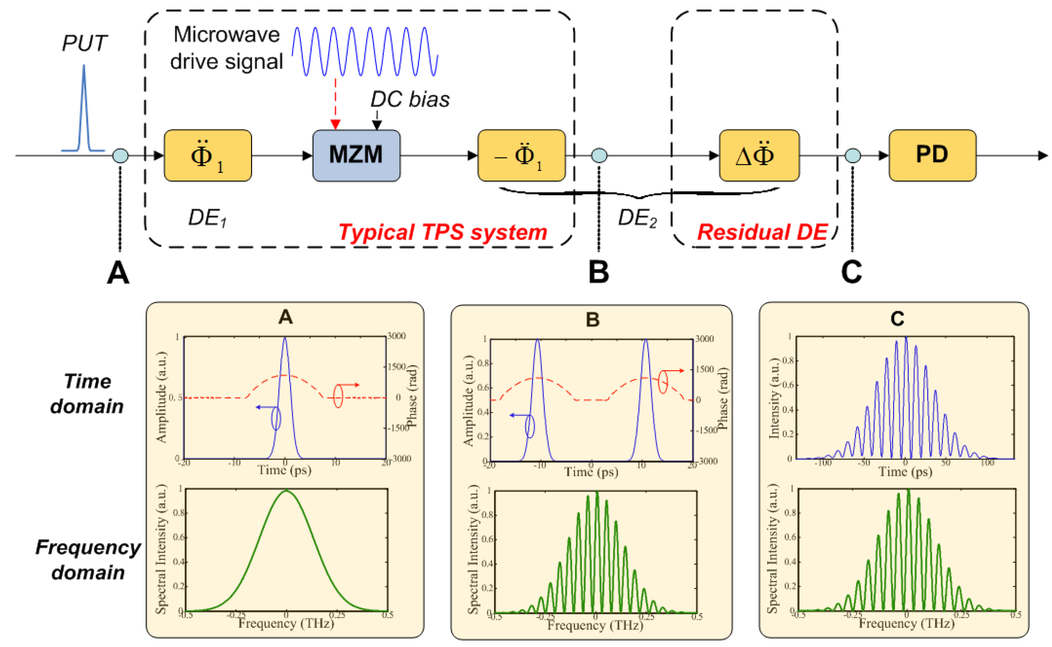
3.2.5. Temporal Fourier Transform Pulse Shaping for Photonic Microwave AWG

Photonic microwave arbitrary waveform generation can also be achieved based on Fourier transform pulse shaping [98,109,110]. Fourier transform pulse shaping is usually implemented in the space domain using a pair of diffraction gratings and a spatial light modulator (SLM) [98]. The spectrum of the optical pulse is dispersed in space by the first grating, modulated by the SLM in the Fourier domain, and then back-transformed by the second grating. Recently, we demonstrate an all-fiber Fourier transform pulse shaping using a single LCFBG [111]. The FBG in the system functions as a conjugate dispersive element pair to perform pulse stretching and pulse compression based on reflection in opposite directions from the FBG, and at the same time as a spectral shaper. The use of a single LCFBG guarantees an exact dispersion matching, featuring a better pulse shaping accuracy with a simplified structure.
Fourier transform pulse shaping can also be implemented in the time domain based on temporal pulse shaping (TPS) technique. The typical TPS system consists of two conjugate dispersive elements and an electro-optic modulator (EOM) that is placed between the two dispersive elements. In the system, an ultrashort optical pulse is temporally stretched by the first dispersive element and then modulated in the time domain by a microwave driving signal at the EOM. The dispersed and modulated optical pulse is finally completely compressed by the second dispersive element with opposite dispersion. At the output of the TPS system, a temporal waveform that is the Fourier transform of the microwave modulation signal is obtained [112].
Figure 9. Schematic an unbalanced TPS system for microwave arbitrary waveform generation based on frequency multiplication. MLL: mode-locked laser, LCFBG: linearly chirped fiber Bragg grating, EOM: electro-optic modulator, PD: photodetector.
Photonics 01 00586 g009
The conventional TPS technique is usually employed for generating ultrafast optical waveforms [111,112]. In fact, this technique can be adapted to achieve the generation of high-frequency microwave waveforms. Recently, we have proposed an unbalanced temporal pulse shaping (UB-TPS) system for the generation of microwave waveforms with continuously tunable carrier frequencies [92]. As shown in Figure 9, the UB-TPS system incorporates two dispersive elements, such as linearly chirped fiber Bragg gratings (LCFBGs) having opposite dispersion but non-identical in magnitude. The entire system can be considered as a conventional balanced TPS system for real-time Fourier transformation of the microwave drive signal, followed by a residual dispersive element with its dispersion being the offset of the dispersion of the two dispersive elements, to achieve a second dispersive Fourier transformation. The finally obtained microwave waveform would be a scaled version of the input modulation signal. The frequency multiplication factor is determined by the dispersion values of the two dispersive elements. For LCFBG-based dispersive elements, their dispersion values can be continuously tunable [113]. In addition, a frequency-multiplied chirped microwave waveform can be generated from single-frequency microwave drive signal using the UB-TPS system if high-order dispersion is involved [114].
Note that various all-fiber photonic microwave AWG systems for generating chirped microwave waveforms have been reviewed in this Section. One key feature of chirped microwave waveforms is their large time-bandwidth product (TBWP) due to frequency chirping and hence making them extensively employed in modern radar systems to improve the range resolution. Table 1 compares the chirp rate and TBWP of chirped microwave waveforms generated using different systems that have been reviewed in this paper. The overall achievable TBWP of the system is limited by the dispersion that enables DFT process.
Table 1. Time-bandwidth product (TBWP) of chirped microwave waveforms that are generated by various all-fiber DFT-based microwave AWG systems.
Systems for Generating Chirped Microwave WaveformsTBWPChirp Rate
Based on superimposed chirped FBGs [103]37.523.8 GHz/ns
Based on Sagnac loop mirror with a chirped FBG [104]44.822 GHz/ns
Based on nonlinear DFT [56]8.474 GHz/ns
Based on spatially-discrete chirped FBG [39]16.8 and 23.211.2–93.6 GHz/ns
Based on temporal Fourier transform pulse shaping [114]1.80.715 GHz/ns

3.3. DFT for Microwave Spectrum Sensing

Microwave spectrum sensing is a recent topic of great interest in microwave photonic; with various scientific; industrial and defense applications; such as wireless communications; radars and electronic warfare [115]. It is a real challenge to monitor the instantaneous spectrum of high-frequency and broadband microwave signals in real-time with high-resolution while having low-cost. Photonically assisted techniques for microwave spectrum measurement have shown superior performance over their electronic counterpart. Many solutions have been proposed for photonic microwave spectrum sensing in the past a few years; including those based on microwave/optical power monitoring [116,117] and channelization [118,119]. Power-monitoring-based technique offers good frequency measurement resolution; usually smaller than 100 MHz. However; it falls short in simultaneously measuring multiple microwave frequencies. Channelization method is capable of multiple microwave frequency measurement based on the direct spectrum sampling using optical channelizers. Its key limitation in microwave spectrum sensing is the poor measurement resolution due to large channel spacing of an optical channelizer; which is usually larger than 1 GHz [117,118].
Figure 10. Schematic of real-time microwave spectrum sensing system based on DFT-enabled temporal channelization.
Photonics 01 00586 g010
Recently, we have proposed and demonstrated a DFT-based temporal channelization method for real-time microwave spectrum sensing [120,121], which does not only enables multiple-frequency detection, but also offers hundreds of times higher frequency measurement resolution than the channel spacing. Figure 10 shows the conceptual diagram of the system. An ultrafast optical pulse is first sent to a dispersive element. The dispersed pulse is then modulated by a microwave signal with its spectrum to be measured. Thanks to the one-to-one mapping between time and spectrum in the DFT process, the pulse spectrum is also modulated by the microwave signal. This process is called time-domain spectral shaping [122]. Finally, the stretched and modulated optical pulse is sent to an optical channelizer for spectrum sampling. In fact, the temporal sampling of the microwave signal is equivalently implemented by the optical channelizer in the spectral domain due to the unique wavelength-to-time mapping. In the system, the frequency measurement resolution is not determined by the physical channel spacing of the channelizer [117,118], but the optical bandwidth of the dispersed pulse and the dispersion value [120]. By broadening the pulse spectrum based on nonlinear optical effects, a frequency resolution as high as 55 MHz can be achieved using an optical channelizer with a channel spacing of 25 GHz [121], which demonstrates nearly 500 times improvement. Moreover, due to the DFT-enabled equivalent parallel-to-serial conversion, no high-speed photodetector and digitizer is required in the system. The system cost is greatly reduced.
One difficulty of the DFT-based temporal-channelization method is the limited operational bandwidth due to the low equivalent temporal sampling rate. According to Shannon-Nyquist sampling theorem, only microwave signals with their bandwidth less than half of the maximum sampling rate can be captured without losing any information. The equivalent temporal sampling rate of the method is inversely proportional to the channel spacing and the dispersion value [121]. It is challenging to further reduce the channel spacing based on the state-of-the-art fabrication technology. While larger dispersion value could improve the sampling rate, it also degrades the frequency measurement solution. On the other hand, it has been reported recently that, for a spectrally-sparse signal, compressive sensing technique enables recovery of the signal with sub-Nyquist sampling [123]. Compressive sensing with photonically-assisted random demodulation has been implemented based on temporal mixing with pseudo-random bit sequences (PRBS) [124,125]. However, sophisticated high-speed electronics is usually required in the PRBS generator and mixer. Most recently, we have proposed a novel sub-Nyquist microwave spectrum sensing scheme that combines temporal channelization and compressive sensing [41], featuring enhanced bandwidth with single-shot measurement capability while maintaining high measurement resolution. Compared to the system in [121], a compressive sensing module is incorporated in the system to manipulate the modulated optical pulse before it is sent to the optical channelizer for sampling. Figure 11a shows the schematic of the compressive sensing module. Random mixing, which is the key step in compressive sensing, is implemented in the spectral domain using a reflective spatial light modulator (R-SLM). A pseudo-random bit sequence (PRBS) pattern is imprinted on the R-SLM. The spectrum of the modulated optical pulse, which carries the microwave signal, can be effectively mixed with the PRBS at the R-SLM, without being converted back to the time domain [124,125]. The randomly mixed spectrum is finally sent to the optical channelizer for downsampling. More importantly, since each channel has a relatively flap response and a wider bandwidth than the spectral resolution of the R-SLM, the output of each channel is the sum of the consecutive elements of the demodulated signal, as shown in Figure 11b, assuring the perfect implementation of sample-and-hold integration. The challenge of implementing high-frequency integration or low-pass filtering in time domain methods [124,125] has been eliminated in the proposed system. Then the Nyquist-sampled microwave signal can be recovered from down-sampled measurements in the digital domain following a sparse signal recovery algorithm [126] thanks to compressive sensing.
Figure 11. Compressive sensing improves the operational bandwidth of the DFT-based microwave spectrum sensing system. (a) Schematic of compressive sensing module based on optical random mixing using a reflective spatial light modulator (R-SLM) with a pseudo-random bit sequence (PRBS) input. (b) Illustration of sample-and-hold integration by spectral filtering in the optical channelizer.
Photonics 01 00586 g011

3.4. DFT for Photonic Analog-to-Digital Conversion (ADC)

High-speed analog-to-digital converters are of paramount importance in modern signal processing and communications systems. The ever-increasing speeds of digital electronics and power of digital signal processing (DSP) units have challenged the operational bandwidth of the state-of-the-art electronic ADCs. Photonic technologies have been widely investigated to enhance the performance of the electronic ADCs [25], through high-speed and low-jitter optical sampling [127], and optical quantization [128,129].
Figure 12. Schematic diagram of DFT-enabled photonic time stretch analog-to-digital conversion (ADC).
Photonics 01 00586 g012
DFT technique has also been employed to boost the bandwidth of electronic ADCs [24,130]. The main efforts here are not to optically sample and quantize the fast analog signal. DFT slows down the analog signal prior to sampling and quantization by an electronic digitizer based on a photonic time stretch process. As illustrated in Figure 12, the analog signal is first modulated onto a dispersed optical pulse thanks to the DFT process achieved in the first dispersive element. A second dispersive element further stretches the modulated optical pulse with its temporal shape being maintained. The original fast analog signal is then slowed down thanks to the DFT-based photonic time stretch process, and can be captured by a low-speed digitizer, which would otherwise have insufficient sampling rate. Photonic time stretch ADC acts as a front-end signal stretcher which enhances the effective sampling rate of any back-end electronic ADCs. The stretch factor is determined by the ratio of the dispersion values of two dispersive element. For a time-limited input signal, a single channel photonic time stretch ADC would suffice, as shown in Figure 12. In order to capture a continuous-time input signal, a multichannel photonic time stretch system involving a segmentation unit can be used [24]. The most recent advances in photonic time stretch ADC include all-optical signal mixing for higher sampling speed , and digital linearization for enhanced dynamic range [131].

4. Conclusions

DFT technology enables pulse-by-pulse real-time spectroscopic measurement and manipulation, making it a unique and emerging tool for ultrafast signal generation and processing, and high-throughput real-time measurements and imaging. This review paper introduces the concept and implementation methods of DFT, and reviews its wide applications in various microwave photonics applications, such as real-time spectroscopy, optical pulse characterization, ultrafast fiber grating sensor interrogation, photonic microwave arbitrary waveform generation, real-time microwave spectrum sensing, and photonic ADC.
DFT-based microwave photonics systems are usually implemented using discrete fiber-optic and electro-optical components, which makes the system bulky, costly, unreliable, and with high power consumption. A solution to reduce the system cost, weight, footprint size and power consumption is to develop chip-scale systems use photonic integrated circuits (PICs). Future work on DFT includes building integrated on-chip microwave photonics systems. One challenge is to develop an integrated dispersive element for chip-scale DFT. Chirped waveguide Bragg gratings can be a good candidate for integrated dispersive element. Efforts will be made to design and fabricate a three-port waveguide circulator to allow the waveguide gratings to work in reflection mode. An alternative solution is to develop a dispersion-engineered waveguide, such as photonic crystal waveguides.

Acknowledgments

This work was supported in part by the Natural Sciences and Engineering Research Council (NSERC) of Canada and in part by EU Marie-Curie Career Integration Grant (FP7-PEOPLE-2013-CIG-631883). The author was supported by NSERC through the Vanier Canada Graduate Scholarship programme, supervised by Professor Jianping Yao of the University of Ottawa, and the NSERC Postdoctoral Fellowship program, supervised by Professor Bahram Jalali of the University of California, Los Angeles (UCLA).

Conflict of Interest

The authors declare no conflict of interest.

References

  1. Seeds, A.J. Microwave photonics. IEEE Trans. Microw. Theory Tech. 2002, 50, 877–887. [Google Scholar] [CrossRef]
  2. Seeds, A.J.; Williams, K.J. Microwave photonics. J. Lightwave Technol. 2006, 24, 4628–4641. [Google Scholar] [CrossRef]
  3. Capmany, J.; Novak, D. Microwave photonics combines two worlds. Nature Photon. 2007, 1, 319–330. [Google Scholar] [CrossRef]
  4. Yao, J.P. Microwave Photonics. J. Lightwave Technol. 2009, 27, 314–335. [Google Scholar] [CrossRef]
  5. Ghelfi, P.; Laghezza, F.; Scotti, F.; Serafino, G.; Capria, A.; Pinna, S.; Onori, D.; Porzi, C.; Scaffardi, M.; Malacarne, A.; et al. A fully photonics-based coherent radar system. Nature 2014, 507, 341–345. [Google Scholar] [CrossRef] [PubMed] [Green Version]
  6. Zmuda, H.; Toughlian, E.N. Photonic Aspects of Modern Radar; Artech House: Norwood, MA USA, 1994. [Google Scholar]
  7. Manka, M.E. Microwave photonics for Electronic Warfare applications. In Proceedings of the international topical meeting on Microwave photonics, 2008 jointly held with the 2008 asia-pacific microwave photonics conference, Gold Coast, Qld, Australia; 2008; pp. 275–278. [Google Scholar]
  8. Mjeku, M.; Gomes, N.J. Performance analysis of 802.11e transmission bursting in fiberfed networks. In Proceedings of the 2008 IEEE Radio and Wireless Symposium, 22–24 January 2008; pp. 133–136.
  9. Business News. Wireless future drives microwave photonics. Nat. Photon. 2011, 5, 724. [Google Scholar]
  10. Sotom, M.; Benazet, B.; Le Kernec, A.; Maignan, M. Microwave photonic technologies for flexible satellite telecom payloads. In Proceedings of the 35th European Conference on Optical Communication, Vienna, Austria, 20–24 September 2009; pp. 1–4.
  11. Isogawa, T.; Kumashiro, T.; Ho-Jin, S.; Ajito, K.; Kukutsu, N.; Iwatsuki, K.; Nagatsuma, T. Tomographic Imaging Using Photonically Generated Low-Coherence Terahertz Noise Sources. IEEE Trans. Terahertz Sci. Technol. 2012, 2, 485–492. [Google Scholar] [CrossRef]
  12. Chi, H.; Zou, X.H.; Yao, J.P. An approach to the measurement of microwave frequency based on optical power monitoring. IEEE Photon. Technol. Lett. 2008, 20, 1249–1251. [Google Scholar] [CrossRef]
  13. Wang, C.; Yao, J.P. Fiber Bragg gratings for microwave photonics subsystems. Opt. Express 2013, 21, 22868–22884. [Google Scholar] [CrossRef] [PubMed]
  14. Guohua, Q.; Jianping, Y.; Seregelyi, J.; Paquet, S.; Belisle, C. Generation and distribution of a wide-band continuously tunable millimeter-wave signal with an optical external modulation technique. IEEE Trans. Microw. Theory Tech. 2005, 53, 3090–3097. [Google Scholar] [CrossRef]
  15. Minasian, R.A.; Chan, E.H.W.; Yi, X. Microwave photonic signal processing. Opt. Express 2013, 21, 22918–22936. [Google Scholar] [CrossRef]
  16. Capmany, J.; Mora, J.; Gasulla, I.; Sancho, J.; Lloret, J.; Sales, S. Microwave Photonic Signal Processing. J. Lightwave Technol. 2013, 31, 571–586. [Google Scholar] [CrossRef]
  17. Frigyes, I.; Seeds, A.J. Optically Generated True-Time Delay in Phased-Array Antennas. IEEE Trans. Microw. Theory Tech. 1995, 43, 2378–2386. [Google Scholar] [CrossRef]
  18. Ortega, B.; Cruz, J.L.; Capmany, J.; Andres, M.V.; Pastor, D. Variable delay line for phased-array antenna based on a chirped fiber grating. IEEE Trans. Microw. Theory Tech. 2000, 48, 1352–1360. [Google Scholar] [CrossRef]
  19. Wake, D.; Nkansah, A.; Gomes, N.J. Radio Over Fiber Link Design for Next Generation Wireless Systems. J. Lightwave Technol. 2010, 28, 2456–2464. [Google Scholar] [CrossRef] [Green Version]
  20. Koonen, A.M.; Larrodé, M.G.; Ng'oma, A.; Wang, K.; Yang, H.; Zheng, Y.; Tangdiongga, E. Perspectives of Radio-over-Fiber Technologies. In Proceedings of the Optical Fiber Communication Conference/National Fiber Optic Engineers Conference, San Diego, CA, USA, 24 February 2008; p. OThP3.
  21. McKinney, J.D.; Leaird, D.E.; Weiner, A.M. Millimeter-wave arbitrary waveform generation with a direct space-to-time pulse shaper. Opt. Lett. 2002, 27, 1345–1347. [Google Scholar] [CrossRef] [PubMed]
  22. Chou, J.; Han, Y.; Jalali, B. Adaptive RF-photonic arbitrary waveform generator. IEEE Photon. Technol. Lett. 2003, 15, 581–583. [Google Scholar] [CrossRef]
  23. Yao, J.P. Photonic generation of microwave arbitrary waveforms. Opt. Commun. 2011, 284, 3723–3736. [Google Scholar] [CrossRef]
  24. Han, Y.; Jalali, B. Photonic time-stretched analog-to-digital converter: Fundamental concepts and practical considerations. J. Lightwave Technol. 2003, 21, 3085–3103. [Google Scholar]
  25. Valley, G.C. Photonic analog-to-digital converters. Opt. Express 2007, 15, 1955–1982. [Google Scholar] [CrossRef]
  26. Marpaung, D.; Roeloffzen, C.; Heideman, R.; Leinse, A.; Sales, S.; Capmany, J. Integrated microwave photonics. Laser Photonics Rev. 2013, 7, 506–538. [Google Scholar] [CrossRef]
  27. Coldren, L.A. Photonic Integrated Circuits for microwave photonics. In Proceedings of the 2010 IEEE Topical Meeting on Microwave Photonics (MWP), Montreal, QC, Canada, 5–9 October 2010; pp. 1–4.
  28. Burla, M.; Cortés, L.R.; Li, M.; Wang, X.; Chrostowski, L.; Azaña, J. Integrated waveguide Bragg gratings for microwave photonics signal processing. Opt. Express 2013, 21, 25120–25147. [Google Scholar] [CrossRef] [PubMed]
  29. Burla, M.; Marpaung, D.; Zhuang, L.M.; Roeloffzen, C.; Khan, M.R.; Leinse, A.; Hoekman, M.; Heideman, R. On-chip CMOS compatible reconfigurable optical delay line with separate carrier tuning for microwave photonic signal processing. Opt. Express 2011, 19, 21475–21484. [Google Scholar] [CrossRef] [PubMed]
  30. Pant, R.; Marpaung, D.; Kabakova, I.V.; Morrison, B.; Poulton, C.G.; Eggleton, B.J. On-chip stimulated Brillouin Scattering for microwave signal processing and generation. Laser Photonics Rev. 2014, 1–14. [Google Scholar]
  31. Goda, K.; Solli, D.R.; Tsia, K.K.; Jalali, B. Theory of amplified dispersive Fourier transformation. Phys. Rev. A 2009, 80, 043821. [Google Scholar] [CrossRef]
  32. Goda, K.; Jalali, B. Dispersive Fourier transformation for fast continuous single-shot measurements. Nat. Photon. 2013, 7, 102–112. [Google Scholar] [CrossRef]
  33. Jannson, T. Real-Time Fourier Transformation in Dispersive Optical Fibers. Opt. Lett. 1983, 8, 232–234. [Google Scholar] [CrossRef] [PubMed]
  34. Muriel, M.A.; Azana, J.; Carballar, A. Real-time Fourier transformer based on fiber gratings. Opt. Lett. 1999, 24, 1–3. [Google Scholar] [CrossRef] [PubMed]
  35. Azana, J.; Chen, L.R.; Muriel, M.A.; Smith, P.W.E. Experimental demonstration of real-time Fourier transformation using linearly chirped fibre Bragg gratings. Electron. Lett. 1999, 35, 2223–2224. [Google Scholar] [CrossRef]
  36. Wang, C.; Zeng, F.; Yao, J.P. All-fiber ultrawideband pulse generation based on spectral-shaping and dispersion-induced frequency-to-time conversion. IEEE Photon. Technol. Lett. 2007, 19, 137–139. [Google Scholar] [CrossRef]
  37. Torres-Company, V.; Leaird, D.E.; Weiner, A.M. Dispersion requirements in coherent frequency-to-time mapping. Opt. Express 2011, 19, 24718–24729. [Google Scholar] [CrossRef] [PubMed]
  38. Jalali, B.; Solli, D.R.; Goda, K.; Tsia, K.; Ropers, C. Real-time measurements, rare events and photon economics. Eur Phys. J.-Spec. Top. 2010, 185, 145–157. [Google Scholar] [CrossRef]
  39. Wang, C.; Yao, J.P. Large time-bandwidth product microwave arbitrary waveform generation using a spatially discrete chirped fiber Bragg grating. J. Lightwave Technol. 2010, 28, 1652–1660. [Google Scholar] [CrossRef]
  40. Wang, C.; Yao, J.P. Ultrahigh-Resolution Photonic-Assisted Microwave Frequency Identification Based on Temporal Channelization. IEEE Trans. Microw. Theory Tech. 2013, 61, 4275–4282. [Google Scholar] [CrossRef]
  41. Wang, C.; Gomes, N.J. Photonics-enabled sub-Nyquist radio frequency sensing based on temporal channelization and compressive sensing. In Proceedings of the 2014 IEEE Topical Meeting on Microwave Photonics (MWP), Sapporo, Japan, 20–23 October 2014; pp. 1–4.
  42. Bhushan, A.S.; Coppinger, F.; Jalali, B. Time-stretched analogue-to-digital conversion. Electron. Lett. 1998, 34, 839–841. [Google Scholar] [CrossRef]
  43. Chou, J.; Boyraz, O.; Solli, D.; Jalali, B. Femtosecond real-time single-shot digitizer. Appl. Phys. Lett. 2007, 91, 161105. [Google Scholar] [CrossRef]
  44. Hult, J.; Watt, R.S.; Kaminski, C.F. High bandwidth absorption spectroscopy with a dispersed supercontinuum source. Opt. Express 2007, 15, 11385–11395. [Google Scholar] [CrossRef] [PubMed]
  45. Chou, J.; Solli, D.R.; Jalali, B. Real-time spectroscopy with subgigahertz resolution using amplified dispersive Fourier transformation. Appl. Phys. Lett. 2008, 92, 111102. [Google Scholar] [CrossRef]
  46. Sych, Y.; Engelbrecht, R.; Schmauss, B.; Kozlov, D.; Seeger, T.; Leipertz, A. Broadband time-domain absorption spectroscopy with a ns-pulse supercontinuum source. Opt. Express 2010, 18, 22762–22771. [Google Scholar] [CrossRef]
  47. Solli, D.R.; Chou, J.; Jalali, B. Amplified wavelength-time transformation for real-time spectroscopy. Nature Photon. 2008, 2, 48–51. [Google Scholar] [CrossRef]
  48. Wang, C.; Yao, J.P. Ultrafast and Ultrahigh-Resolution Interrogation of a Fiber Bragg Grating Sensor Based on Interferometric Temporal Spectroscopy. J. Lightwave Technol. 2011, 29, 2927–2933. [Google Scholar] [CrossRef]
  49. Xia, H.Y.; Wang, C.; Blais, S.; Yao, J.P. Ultrafast and Precise Interrogation of Fiber Bragg Grating Sensor Based on Wavelength-to-Time Mapping Incorporating Higher Order Dispersion. J. Lightwave Technol. 2010, 28, 254–261. [Google Scholar] [CrossRef]
  50. Goda, K.; Tsia, K.K.; Jalali, B. Serial time-encoded amplified imaging for real-time observation of fast dynamic phenomena. Nature 2009, 458, 1145–1149. [Google Scholar] [CrossRef] [PubMed]
  51. Goda, K.; Mahjoubfar, A.; Wang, C.; Fard, A.; Adam, J.; Gossett, D.R.; Ayazi, A.; Sollier, E.; Malik, O.; Chen, E.; et al. Hybrid Dispersion Laser Scanner. Sci. Rep. 2012, 2, 445. [Google Scholar] [CrossRef] [PubMed]
  52. Kolner, B.H. Space-Time Duality and the Theory of Temporal Imaging. IEEE J. Quant. Electron. 1994, 30, 1951–1963. [Google Scholar] [CrossRef]
  53. Papoulis, A. Pulse compression, fiber communications, and diffraction: A unified approach. J. Opt. Soc. Am. A 1994, 11, 3–13. [Google Scholar] [CrossRef]
  54. Xia, H.Y.; Yao, J.P. Characterization of Subpicosecond Pulses Based on Temporal Interferometry with Real-Time Tracking of Higher Order Dispersion and Optical Time Delay. J. Lightwave Technol. 2009, 27, 5029–5037. [Google Scholar] [CrossRef]
  55. Gupta, S.; Jalali, B. Time-warp correction and calibration in photonic time-stretch analog-to-digital converter. Opt. Lett. 2008, 33, 2674–2676. [Google Scholar] [CrossRef] [PubMed]
  56. Wang, C.; Yao, J.P. Photonic generation of chirped millimeter-wave pulses based on Nonlinear frequency-to-time mapping in a nonlinearly chirped fiber bragg grating. IEEE Trans. Microw. Theory Tech. 2008, 56, 542–553. [Google Scholar] [CrossRef]
  57. Xu, Y.; Shi, Z.; Chi, H.; Jin, X.; Zheng, S.; Zhang, X. Relaxed dispersion requirement in the generation of chirped RF signals based on frequency-to-time mapping. Opt. Commun. 2014, 331, 278–281. [Google Scholar] [CrossRef]
  58. Solli, D.R.; Gupta, S.; Jalali, B. Optical phase recovery in the dispersive Fourier transform. Appl. Phys. Lett. 2009, 95, 231108. [Google Scholar] [CrossRef]
  59. Dezfooliyan, A.; Weiner, A.M. Photonic synthesis of high fidelity microwave arbitrary waveforms using near field frequency to time mapping. Opt. Express 2013, 21, 22974–22987. [Google Scholar] [CrossRef] [PubMed]
  60. Huang, C.-P.; Kapteyn, H.C.; McIntosh, J.W.; Murnane, M.M. Generation of transform-limited 32-fs pulses from a self-mode-locked Ti:sapphire laser. Opt. Lett. 1992, 17, 139–141. [Google Scholar] [CrossRef]
  61. Kobayashi, T.; Yao, H.; Amano, K.; Fukushima, Y.; Morimoto, A.; Sueta, T. Optical pulse compression using high-frequency electrooptic phase modulation. IEEE J. Quant. Electron. 1988, 24, 382–387. [Google Scholar]
  62. Komukai, T.; Yamamoto, T.; Kawanishi, S. Optical pulse generator using phase modulator and linearly chirped fiber Bragg gratings. IEEE Photon. Technol. Lett. 2005, 17, 1746–1748. [Google Scholar] [CrossRef]
  63. Saperstein, R.E.; Panasenko, D.; Fainman, Y. Demonstration of a microwave spectrum analyzer based on time-domain optical processing in fiber. Opt. Lett. 2004, 29, 501–503. [Google Scholar] [CrossRef]
  64. Chi, H.; Yao, J. All-fiber chirped microwave pulses generation based on spectral shaping and wavelength-to-time conversion. IEEE Trans. Microw. Theory Tech. 2007, 55, 1958–1963. [Google Scholar] [CrossRef]
  65. Wang, C.; Yao, J.P. Complete Characterization of an Optical Pulse Based on Temporal Interferometry Using an Unbalanced Temporal Pulse Shaping System. J. Lightwave Technol. 2011, 29, 789–800. [Google Scholar] [CrossRef]
  66. Hill, K.O.; Malo, B.; Bilodeau, F.; Johnson, D.C.; Albert, J. Bragg gratings fabricated in monomode photosensitive optical fiber by UV exposure through a phase mask. Appl. Phys. Lett. 1993, 62, 1035–1037. [Google Scholar] [CrossRef]
  67. Erdogan, T. Fiber grating spectra. J. Lightwave Technol. 1997, 15, 1277–1294. [Google Scholar] [CrossRef]
  68. Capmany, J.; Pastor, D.; Ortega, B.; Cruz, J.L.; Andres, M.V. Applications of fiber Bragg gratings to microwave photonics. Fiber Integrated Opt. 2000, 19, 483–494. [Google Scholar] [CrossRef]
  69. Wang, C.; Yao, J.P. Fiber Bragg gratings for microwave photonics applications. In Microwave Photonics, 2nd ed.; Lee, C.H., Ed.; CRC Press: Boca Raton, FL, USA, 2013; pp. 125–174. [Google Scholar]
  70. Kashyap, R. Fiber Bragg Gratings; Academic Press: San Diego, CA, USA, 1999. [Google Scholar]
  71. Chi, H.; Yao, J. Chirped RF Pulse Generation Based on Optical Spectral Shaping and Wavelength-to-Time Mapping Using a Nonlinearly Chirped Fiber Bragg Grating. J. Lightwave Technol. 2008, 26, 1282–1287. [Google Scholar] [CrossRef]
  72. Kashyap, R.; de Lacerda Rocha, M. On the group delay characteristics of chirped fibre Bragg gratings. Opt. Commun. 1998, 153, 19–22. [Google Scholar] [CrossRef]
  73. Tan, Z.W.; Wang, C.; Diebold, E.D.; Hon, N.K.; Jalali, B. Real-time wavelength and bandwidth-independent optical integrator based on modal dispersion. Opt. Express 2012, 20, 14109–14116. [Google Scholar] [CrossRef] [PubMed]
  74. Diebold, E.D.; Hon, N.K.; Tan, Z.; Chou, J.; Sienicki, T.; Wang, C.; Jalali, B. Giant tunable optical dispersion using chromo-modal excitation of a multimode waveguide. Opt. Express 2011, 19, 23809–23817. [Google Scholar] [CrossRef] [PubMed]
  75. Wong, T.T.W.; Lau, A.K.S.; Wong, K.K.Y.; Tsia, K.K. Optical time-stretch confocal microscopy at 1 mu m. Opt. Lett. 2012, 37, 3330–3332. [Google Scholar] [CrossRef] [PubMed]
  76. Lau, A.K.S.; Wong, T.T.W.; Ho, K.K.Y.; Tang, M.T.H.; Chan, A.C.S.; Wei, X.; Lam, E.Y.; Shum, H.C.; Wong, K.K.Y.; Tsia, K.K. Interferometric time-stretch microscopy for ultrafast quantitative cellular and tissue imaging at 1 mu m. J. Biomed. Opt. 2014, 19, 076001. [Google Scholar] [CrossRef]
  77. Wang, C.; Goda, K.; Ibsen, M.; Jalali, B. Dispersive Fourier transformation in the 800 nm spectral range. In Proceedings of the Conference on Lasers and Electro-Optics 2012, San Jose, CA, USA, 6–11 May 2012; p. ATu2G.2.
  78. Torres-Company, V.; Lancis, J.; Andrés, P. Incoherent frequency-to-time mapping: application to incoherent pulse shaping. J. Opt. Soc. Am. A 2007, 24, 888–894. [Google Scholar] [CrossRef]
  79. Torres-Company, V.; Lancis, J.; Andres, P.; Chen, L.R. 20 GHz arbitrary radio-frequency waveform generator based on incoherent pulse shaping. Opt. Express 2008, 16, 21564–21569. [Google Scholar] [CrossRef] [PubMed]
  80. Dorrer, C. Statistical analysis of incoherent pulse shaping. Opt. Express 2009, 17, 3341–3352. [Google Scholar] [CrossRef] [PubMed]
  81. Azana, J.; Muriel, M.A. Real-time optical spectrum analysis based on the time-space duality in chirped fiber gratings. IEEE J. Quant. Electron. 2000, 36, 517–526. [Google Scholar] [CrossRef]
  82. Tong, Y.C.; Chan, L.Y.; Tsang, H.K. Fibre dispersion or pulse spectrum measurement using a sampling oscilloscope. Electron. Lett. 1997, 33, 983–985. [Google Scholar] [CrossRef]
  83. Kelkar, P.V.; Coppinger, F.; Bhushan, A.S.; Jalali, B. Time-domain optical sensing. Electron. Lett. 1999, 35, 1661–1662. [Google Scholar] [CrossRef]
  84. Chou, J.; Han, Y.; Jalali, B. Time-wavelength spectroscopy for chemical sensing. IEEE Photon. Technol. Lett. 2004, 16, 1140–1142. [Google Scholar] [CrossRef]
  85. Dennis, M.L.; Putnam, M.A.; Kang, J.U.; Tsai, T.E.; Duling, I.N.; Friebele, E.J. Grating sensor array demodulation by use of a passively mode-locked fiber laser. Opt. Lett. 1997, 22, 1362–1364. [Google Scholar] [CrossRef] [PubMed]
  86. Yao, J.; Wang, C. Superimposed Oppositely Chirped FBGs for Ultrafast FBG Sensor Interrogation with Significantly Improved Resolution. In Proceedings of the Sensor and Signal Processing Applications (BThB), Karlsruhe Germany, 21–24 June 2010.
  87. Liu, W.L.; Li, M.; Wang, C.; Yao, J.P. Real-Time Interrogation of a Linearly Chirped Fiber Bragg Grating Sensor Based on Chirped Pulse Compression With Improved Resolution and Signal-to-Noise Ratio. J. Lightwave Technol. 2011, 29, 1239–1247. [Google Scholar] [CrossRef]
  88. Fu, H.Y.; Liu, H.L.; Dong, X.; Tam, H.Y.; Wai, P.K.A.; Lu, C. High-speed fibre Bragg grating sensor interrogation using dispersion-compensation fibre. Electron. Lett. 2008, 44, 618–619. [Google Scholar] [CrossRef]
  89. Rao, Y.J. In-fibre Bragg grating sensors. Meas. Sci. Technol. 1997, 8, 355–375. [Google Scholar] [CrossRef]
  90. Iaconis, C.; Walmsley, I.A. Self-referencing spectral interferometry for measuring ultrashort optical pulses. IEEE J. Quant. Electron. 1999, 35, 501–509. [Google Scholar] [CrossRef]
  91. Berger, N.K.; Levit, B.; Smulakovsky, V.; Fischer, B. Complete characterization of optical pulses by real-time spectral interferometry. Appl. Opt. 2005, 44, 7862–7866. [Google Scholar] [CrossRef] [PubMed]
  92. Wang, C.; Li, M.; Yao, J.P. Continuously Tunable Photonic Microwave Frequency Multiplication by Use of an Unbalanced Temporal Pulse Shaping System. IEEE Photon. Technol. Lett. 2010, 22, 1285–1287. [Google Scholar] [CrossRef]
  93. Wang, C.; Chi, H.; Yao, J. Photonic generation and processing of millimeter-wave arbitrary waveforms. In Proceedings of the 21st Annual Meeting of the IEEE Lasers and Electro-Optics Society, Newport Beach, CA, USA, 9–13 November 2008; pp. 346–347.
  94. McKinney, J.D.; Seo, D.S.; Weiner, A.M. Photonically assisted generation of continuous arbitrary millimetre electromagnetic waveforms. Electron. Lett. 2003, 39, 309–311. [Google Scholar] [CrossRef]
  95. Leaird, D.E.; Weiner, A.M. Femtosecond direct space-to-time pulse shaping in an integrated-optic configuration. Opt. Lett. 2004, 29, 1551–1553. [Google Scholar] [CrossRef] [PubMed]
  96. Dai, Y.T.; Yao, J.P. Nonuniformly Spaced Photonic Microwave Delay-Line Filters and Applications. IEEE Trans. Microw. Theory Tech. 2010, 58, 3279–3289. [Google Scholar] [CrossRef]
  97. Dai, Y.T.; Yao, J.P. Chirped Microwave Pulse Generation Using a Photonic Microwave Delay-Line Filter With a Quadratic Phase Response. IEEE Photon. Technol. Lett. 2009, 21, 569–571. [Google Scholar] [CrossRef]
  98. Weiner, A.M. Femtosecond pulse shaping using spatial light modulators. Rev. Sci. Instrum. 2000, 71, 1929–1960. [Google Scholar] [CrossRef]
  99. Lin, I.S.; McKinney, J.D.; Weiner, A.M. Photonic synthesis of broadband microwave arbitrary waveforms applicable to ultra-wideband communication. IEEE Microw. Wireless Compon. Lett. 2005, 15, 226–228. [Google Scholar]
  100. Khan, M.H.; Shen, H.; Xuan, Y.; Zhao, L.; Xiao, S.; Leaird, D.E.; Weiner, A.M.; Qi, M. Ultrabroad-bandwidth arbitrary radiofrequency waveform generation with a silicon photonic chip-based spectral shaper. Nature Photon. 2010, 4, 117–122. [Google Scholar] [CrossRef]
  101. Yao, J.P. Photonics for Ultrawideband Communications. IEEE Microw. Mag. 2009, 10, 82–95. [Google Scholar] [CrossRef]
  102. Zeitouny, A.; Stepanov, S.; Levinson, O.; Horowitz, M. Optical generation of linearly chirped microwave pulses using fiber Bragg gratings. IEEE Photon. Technol. Lett. 2005, 17, 660–662. [Google Scholar] [CrossRef]
  103. Wang, C.; Yao, J.P. Photonic generation of chirped microwave pulses using superimposed chirped fiber Bragg gratings. IEEE Photon. Technol. Lett. 2008, 20, 882–884. [Google Scholar] [CrossRef]
  104. Wang, C.; Yao, J.P. Chirped Microwave Pulse Generation Based on Optical Spectral Shaping and Wavelength-to-Time Mapping Using a Sagnac Loop Mirror Incorporating a Chirped Fiber Bragg Grating. J. Lightwave Technol. 2009, 27, 3336–3341. [Google Scholar] [CrossRef]
  105. Li, M.; Yao, J.P. Photonic Generation of Continuously Tunable Chirped Microwave Waveforms Based on a Temporal Interferometer Incorporating an Optically Pumped Linearly Chirped Fiber Bragg Grating. IEEE Trans. Microw. Theory Tech. 2011, 59, 3531–3537. [Google Scholar] [CrossRef]
  106. Chi, H.; Yao, J.P. All-fiber chirped microwave pulses generation based on spectral shaping and wavelength-to-time conversion. IEEE Trans. Microw. Theory Tech. 2007, 55, 1958–1963. [Google Scholar] [CrossRef]
  107. Wang, C.; Yao, J.P. Simultaneous Optical Spectral Shaping and Wavelength-to-Time Mapping for Photonic Microwave Arbitrary Waveform Generation. IEEE Photon. Technol. Lett. 2009, 21, 793–795. [Google Scholar] [CrossRef]
  108. Wang, C.; Yao, J.P. Phase-coded millimeter-wave waveform generation using a spatially discrete chirped fiber Bragg grating. IEEE Photon. Technol. Lett. 2012, 24, 1493–1495. [Google Scholar] [CrossRef]
  109. Heritage, J.P.; Weiner, A.M. Optical systems and methods based upon temporal stretching, modulation and recompression of ultrashort pulses. U.S. patent 4,928,316, 1990. [Google Scholar]
  110. Saperstein, R.E.; Alic, N.; Panasenko, D.; Rokitski, R.; Fainman, Y. Time-domain waveform processing by chromatic dispersion for temporal shaping of optical pulses. J. Opt. Soc. Am. B 2005, 22, 2427–2436. [Google Scholar] [CrossRef]
  111. Wang, C.; Yao, J.P. Fourier Transform Ultrashort Optical Pulse Shaping Using a Single Chirped Fiber Bragg Grating. IEEE Photon. Technol. Lett. 2009, 21, 1375–1377. [Google Scholar] [CrossRef]
  112. Chi, H.; Yao, J.P. Symmetrical waveform generation based on temporal pulse shaping using amplitude-only modulator. Electron. Lett. 2007, 43, 415–417. [Google Scholar] [CrossRef]
  113. Liu, Y.Q.; Yang, J.L.; Yao, J.P. Continuous true-time-delay beamforming for phased array antenna using a tunable chirped fiber grating delay line. IEEE Photon. Technol. Lett. 2002, 14, 1172–1174. [Google Scholar] [CrossRef]
  114. Li, M.; Wang, C.; Li, W.Z.; Yao, J.P. An unbalanced temporal pulse-shaping system for chirped microwave waveform generation. IEEE Trans. Microw. Theory Tech. 2010, 58, 2968–2975. [Google Scholar] [CrossRef]
  115. Hogan, J. Microwave data refine picture of Universe. Nature 2006, 440, 395–395. [Google Scholar] [CrossRef] [PubMed]
  116. Nguyen, L.V.T.; Hunter, D.B. A photonic technique for microwave frequency measurement. IEEE Photon. Technol. Lett. 2006, 18, 1188–1190. [Google Scholar] [CrossRef]
  117. Li, Z.; Wang, C.; Li, M.; Chi, H.; Zhang, X.; Yao, J. Instantaneous microwave frequency measurement using a special fiber Bragg grating. IEEE Microw. Wireless Compon. Lett. 2011, 21, 52–54. [Google Scholar] [CrossRef]
  118. Winnall, S.T.; Lindsay, A.C.; Austin, M.W.; Canning, J.; Mitchell, A. A microwave channelizer and spectroscope based on an integrated optical Bragg-grating Fabry-Perot and integrated hybrid fresnel lens system. IEEE Trans. Microw. Theory Tech. 2006, 54, 868–872. [Google Scholar] [CrossRef]
  119. Wang, W.; Davis, R.L.; Jung, T.J.; Lodenkamper, R.; Lembo, L.J.; Brock, J.C.; Wu, M.C. Characterization of a coherent optical RF channelizer based on a diffraction grating. IEEE Trans. Microw. Theory Tech. 2001, 49, 1996–2001. [Google Scholar] [CrossRef]
  120. Wang, C.; Yao, J. High-resolution microwave frequency measurement based on temporal channelization using a mode-locked laser. In Proceedings of the 2012 IEEE MTT-S International Microwave Symposium Digest (MTT), Montreal, Canada, 17–22 June 2012; pp. 1–3.
  121. Wang, C.; Yao, J. Ultrahigh-resolution photonic-assisted microwave frequency identification based on temporal channelization. IEEE Trans. Microw. Theory Tech. 2013, 61, 4275–4282. [Google Scholar]
  122. Chou, P.C.; Haus, H.A.; Brennan Iii, J.F. Reconfigurable time-domain spectral shaping of an optical pulse stretched by a fiber Bragg grating. Opt. Lett. 2000, 25, 524–526. [Google Scholar] [CrossRef]
  123. Baraniuk, R.G. Compressive Sensing [Lecture Notes]. IEEE Signal. Process. Mag. 2007, 24, 118–121. [Google Scholar]
  124. Nichols, J.M.; Bucholtz, F. Beating Nyquist with light: a compressively sampled photonic link. Opt. Express 2011, 19, 7339–7348. [Google Scholar] [CrossRef] [PubMed]
  125. Chi, H.; Mei, Y.; Chen, Y.; Wang, D.; Zheng, S.; Jin, X.; Zhang, X. Microwave spectral analysis based on photonic compressive sampling with random demodulation. Opt. Lett. 2012, 37, 4636–4638. [Google Scholar] [PubMed]
  126. Figueiredo, M.A.T.; Nowak, R.D.; Wright, S.J. Gradient Projection for Sparse Reconstruction: Application to Compressed Sensing and Other Inverse Problems. Ieee J.-Stsp. 2007, 1, 586–597. [Google Scholar]
  127. Walden, R.H. Analog-to-digital converter survey and analysis. IEEE J. Sel. Areas Commun. 1999, 17, 539–550. [Google Scholar] [CrossRef]
  128. Taylor, H.F. An optical analog-to-digital converter−Design and analysis. IEEE J. Quantum Electron. 1979, 15, 210–216. [Google Scholar] [CrossRef]
  129. Jalali, B.; Xie, Y.M. Optical Folding-Flash Analog-to-Digital Converter with Analog Encoding. Opt. Lett. 1995, 20, 1901–1903. [Google Scholar] [CrossRef] [PubMed]
  130. Coppinger, F.; Bhushan, A.S.; Jalali, B. Photonic time stretch and its application to analog-to-digital conversion. IEEE Trans. Microw. Theory Tech. 1999, 47, 1309–1314. [Google Scholar] [CrossRef]
  131. Fard, A.; Gupta, S.; Jalali, B. Digital broadband linearization technique and its application to photonic time-stretch analog-to-digital converter. Opt. Lett. 2011, 36, 1077–1079. [Google Scholar] [CrossRef] [PubMed]

