Article

Fiber-Based Polarization Diversity Detection for Polarization-Sensitive Optical Coherence Tomography

Integrative Oncology Department-Imaging Unit, BC Cancer Research Center, 675 West 10th Avenue, Vancouver, Canada
*
Author to whom correspondence should be addressed.
Photonics 2014, 1(4), 283-295; https://doi.org/10.3390/photonics1040283
Submission received: 28 August 2014 / Revised: 26 September 2014 / Accepted: 26 September 2014 / Published: 30 September 2014
(This article belongs to the Special Issue Biomedical Optics and Optical Imaging)

Abstract

:
We present a new fiber-based polarization diversity detection (PDD) scheme for polarization sensitive optical coherence tomography (PSOCT). This implementation uses a new custom miniaturized polarization-maintaining fiber coupler with single mode (SM) fiber inputs and polarization maintaining (PM) fiber outputs. The SM fiber inputs obviate matching the optical lengths of the two orthogonal OCT polarization channels prior to interference while the PM fiber outputs ensure defined orthogonal axes after interference. Advantages of this detection scheme over those with bulk optics PDD include lower cost, easier miniaturization, and more relaxed alignment and handling issues. We incorporate this PDD scheme into a galvanometer-scanned OCT system to demonstrate system calibration and PSOCT imaging of an achromatic quarter-wave plate, fingernail in vivo, and chicken breast, salmon, cow leg, and basa fish muscle samples ex vivo.

1. Introduction

Optical coherence tomography (OCT) is an interferometric technique that can image tissue morphology with less than 10 μm axial resolution and more than 1 mm of sub-surface imaging depth [1,2,3]. Image contrast in structural OCT imaging is generated by tissue scattering and reflection due to refractive index interfaces. Although a wealth of information can be gained from purely structural OCT imaging, the desire for more detailed tissue differentiation has given rise to various OCT extensions. One such extension, polarization-sensitive OCT (PSOCT), can provide information about tissue birefringence, diattenuation, optic axis orientation, and depolarization by analyzing the polarization state of back-scattered light. Using PSOCT, highly organized tissue layers such as muscle, bones, and blood vessel walls can be identified by their innate birefringence. Some preliminary clinical applications of PSOCT imaging include the determination of burn depth in vivo [4], the measurement of collagen and smooth muscle cell content in atherosclerotic plaques [5], the differentiation of benign lesions from malignant lesions in the larynx [6], and the detection of nerve fiber bundle loss in glaucoma [7,8].
In general, PSOCT imaging has two essential requirements. Firstly, the incident light on the sample needs to have known polarization states (commonly circular polarization) or multiple sequential polarization states (not necessarily known) with defined polarization relation between them. The former case has some limitations for imaging layered birefringent samples but can be readily achieved in free-space PSOCT systems with Michelson interferometers made with bulk optical components as the polarization state of the light is preserved when propagating in free-space [9,10,11,12,13,14,15,16]. Multiple polarization state illumination can overcome the limitations of known polarization state illumination but requires additional active components such as electro-optic polarization modulators [17,18,19,20,21,22], frequency modulators [23,24], or passive components [25,26] to generate the required polarization states. There is some impetus to use fiber-optic components for PSOCT interferometers due to their lower cost, easier alignment, compactness, and the ability to implement higher signal-to-noise ratio (SNR) Mach-Zehnder OCT interferometers [27]. Fiber-optic implementations are also required for endoscopic applications [22,24,28,29,30]. Fiber optic interferometers using single mode (SM) fiber have the advantage of the availability of inexpensive couplers and circulators but require correction for the change in the polarization state of light introduced by SM fiber using multiple polarization state illumination or polarization controllers. Polarization-maintaining (PM) fiber couplers have been used to build PSOCT systems mostly with Michelson-type interferometers [31,32,33,34,35] as efficient PM fiber-based Mach-Zehnder interferometers require PM circulators [36].
The second requirement for PSOCT is to detect the polarization of light scattered from the sample using a so-called polarization diversity detection (PDD) scheme. Implementation of PDD schemes using free-space bulk optical components [22,23,24,25,26] is costly and requires the alignment of multiple beam splitters and collimators. SM Fiber-based PDD schemes using unbalanced receivers [18,19,20] and balanced receivers with 50/50 SM fiber couplers [37] have been demonstrated. Systems with unbalanced receivers have less SNR compared to systems with balanced receivers due to lower detector dynamic range [27]. Balanced PDD schemes with 50/50 SM fiber couplers require additional polarization controllers and calibration steps to maintain well-defined X and Y axes after interference. PM fiber-base PDD schemes with 50/50 PM fiber couplers have been reported [21,35,36]. In the balanced PDD schemes with PM fiber couplers, due to the large birefringence of PM fiber, the lengths of the coupler input pigtails must be precisely matched to avoid different optical path lengths for X and Y images or additional post-processing is required [21,34].
This work presents a PSOCT system with a new fiber-based PDD scheme consisting of a hybrid custom 50/50 fiber combiner with SM fiber input ports and PM fiber output ports to combine the sample and reference arms. The SM fiber input ports relieve the requirement for precise length matching prior to interference and the PM fiber output ports ensure well-defined orthogonal axes after interference. We have previously demonstrated the utility of this PDD scheme for reducing polarization artefacts in fiber optic rotary probe OCT imaging [38]. In this work, we demonstrate the calibration (necessary for quantitative measurements) and imaging capabilities of this PDD scheme in a benchtop galvanometer scanned PSOCT system using circularly polarized incident light. The performance of the system was evaluated by imaging an achromatic quarter-wave plate, fingernail in vivo and chicken breast, salmon, cow leg, and basa fish muscle samples ex vivo.

2. Materials and Methods
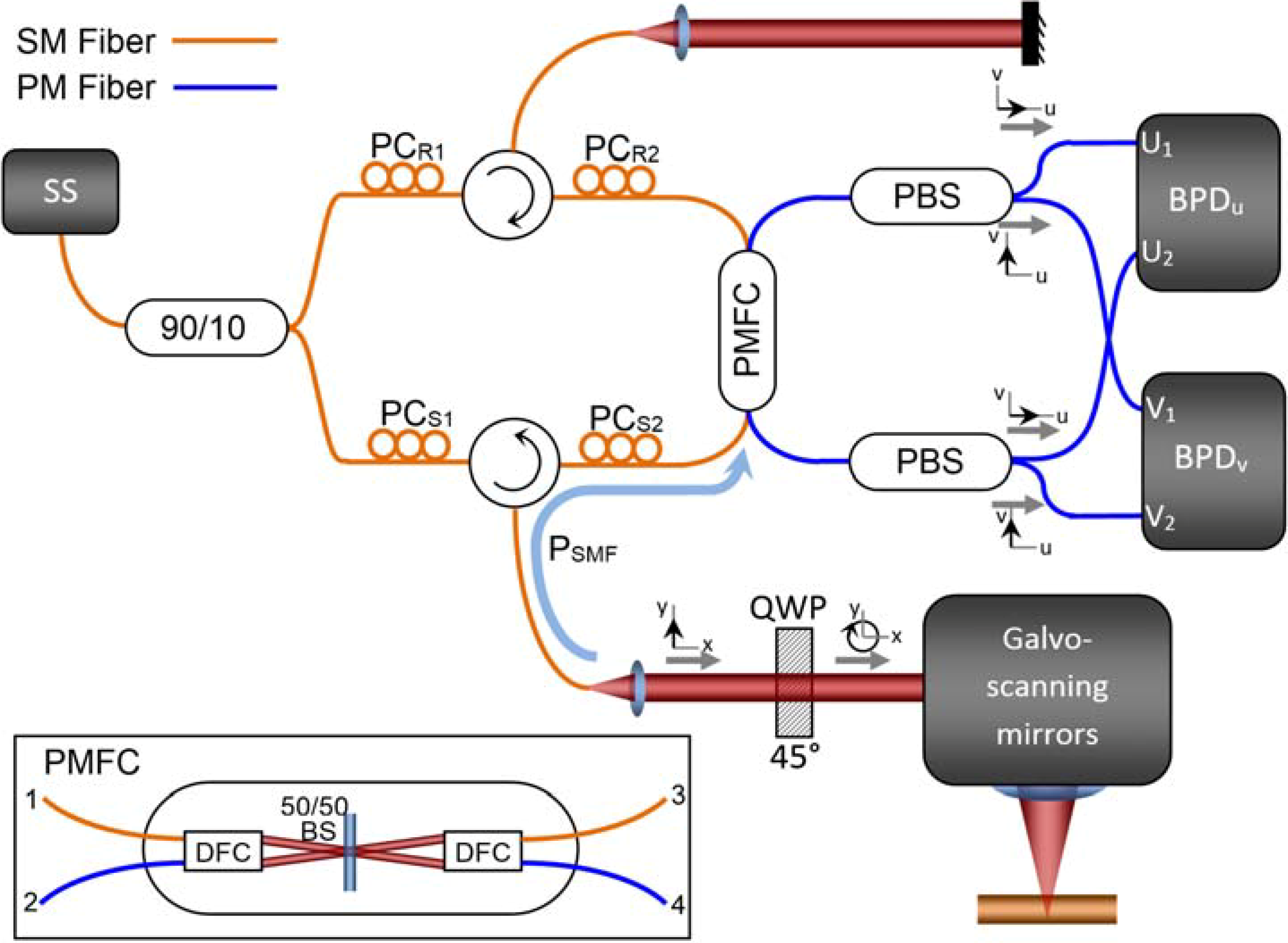
2.1. Imaging System

The experimental PSOCT system is schematically shown in Figure 1. It is driven by a 40 kHz polygon swept laser source, based on the design described by Yun et al. [39], with 106.8-nm bandwidth centered at 1321.4 nm and 30 mW output power. Unless otherwise specified, all fiber optic components were purchased from AFW Technologies, Hallam, Australia. A Mach-Zehnder OCT interferometer is implemented using a single mode 90/10 splitter, polarization controllers PCR1, PCS1, PCR2, PCS2 (PLC-M02-NC-7, General Photonics, Chino, CA, USA), circulators, and a custom hybrid 50/50 coupler (PMFC, shown in detail in the inset) with SM fiber inputs and PM fiber outputs. In this custom micro-optic PMFC ordered from AFW Technologies (Hallamn Australia), the optical beam entering either port 1 or 3 is collimated by dual fiber collimators (DFC) and is divided into two roughly equal beams by a non-polarizing beamsplitter (50/50 BS in the inset), which are subsequently coupled to output ports 2 and 4 with DFCs. The PM fiber outputs are spliced to polarizing beam splitters (PBS). Polarization matched outputs from the PBSs are connected to a pair of 75 MHz balanced detectors (PDB420A, ThorLabs Inc.) constituting two orthogonal detection channels (BPDu and BPDv). The total insertion loss of the PMFC-PBS assembly was measured to be [U1,U2,V1,V2] = [3.72,3.63,3.74,3.71] dB for light input at port 1 and [4.07,3.98,3.75,3.71] dB for port 3 (±40 nm 3dB bandwidth). The PMFC’s SM fiber inputs obviate optical path length matching of the sample and reference coupler input pigtails prior to interference at the PMFC. If the PMFC has PM fiber inputs, the lengths of these two fiber segments must be matched to less than the beat length of the PM fiber or else post-processing is required to compensate the corresponding axial shift between images from the two orthogonal channels. The PMFC PM fiber outputs ensure defined orthogonal axes for u and v detection channels.
A quarter-wave plate (QWP, RABQ-1600, ThorLabs Inc., Newton, NJ, USA) with its fast axis oriented at 45° relative to the x-axis (x and y are the laboratory frame coordinate axes) ensures linear polarized light along x or y is transferred into circularly-polarized light before the sample. This allows polarization measurements insensitive to sample rotation about the axis defined by the incoming beam [9]. Galvo-scanning mirrors (GVS002, ThorLabs Inc.) provide a 2D raster scan of the OCT beam on the sample. The OCT data streams from two detection channels are read simultaneously by a 14-bit digitizer (ATS460, AlazarTech, Pointe-Clare, QC, Canada) using the k-clock from the polygon swept laser source with 40 kHz repetition rate.
The sensitivity of the system was measured to be 93 dB using a calibrated 36 dB attenuator. This measured sensitivity is less than the theoretical expectation of 106 dB and experimental values previously reported for standard Fourier-domain OCT systems. We attribute this difference to imperfect balanced detection, spectral variation in the optical components, and fiber-recoupling loss in the sample arm. The axial resolution was measured to be 11 µm by measuring the axial point spread function when imaging thought a cover slip and the lateral resolution was measured to be 20 µm using the knife-edge technique.
Figure 1. Polarization sensitive optical coherence tomography (PSOCT) system; SS: swept source, PC: polarization controller, QWP: quarter-wave plate, PBS: polarizing beam splitter, PMFC: polarization maintaining fiber coupler, BPD: balanced photo-detector. Inset: Internal schematic of the micro-optic 50/50 PMFC; DFC: dual fiber collimator, 50/50 BS: non-polarizing 50/50 beamsplitter.
Photonics 01 00283 g001

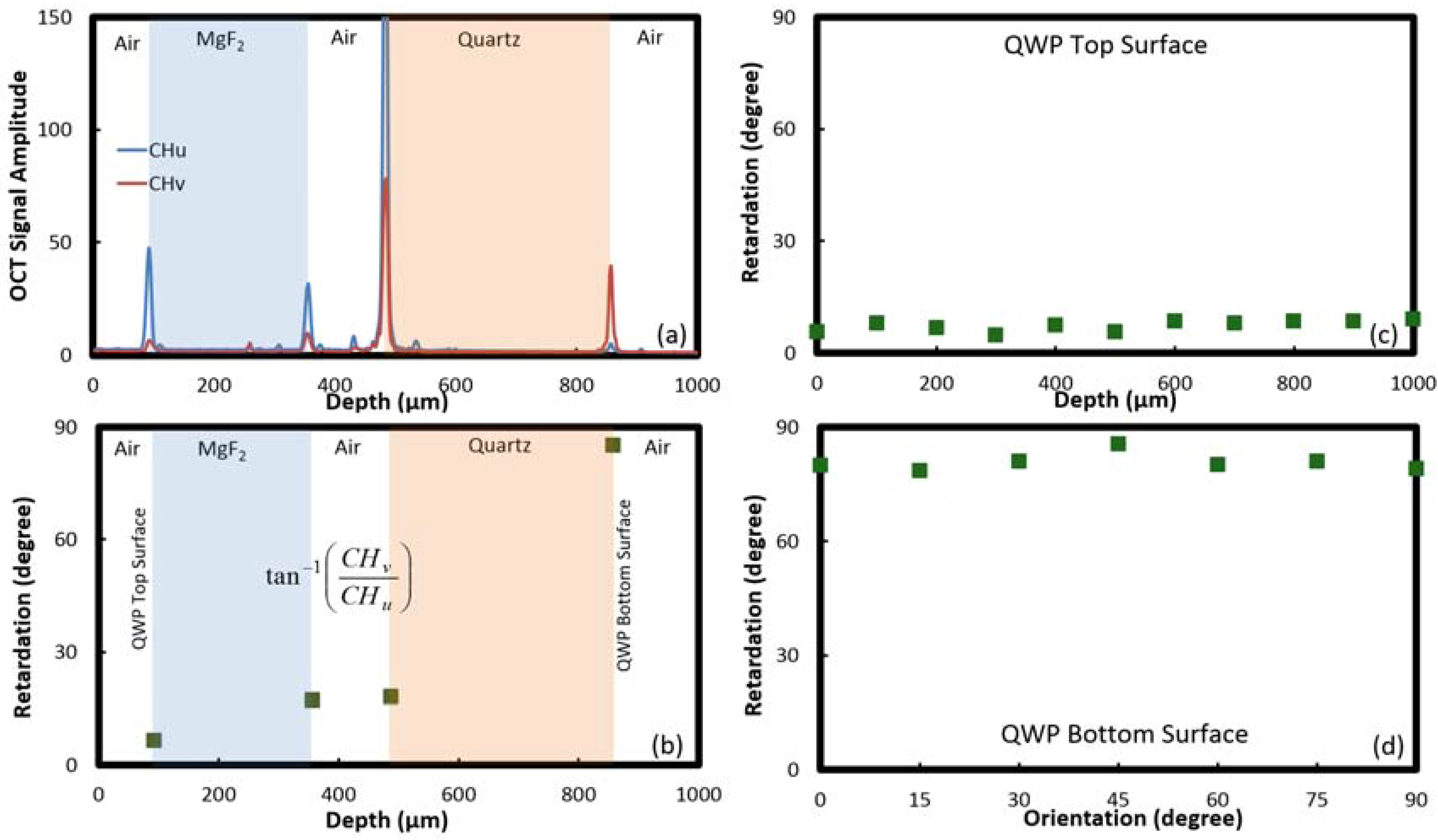
2.2. System Calibration

To ensure light exiting the sample arm collimator is y-polarized, an x-axis oriented (crossed) polarizer is inserted and the power is extinguished by adjusting PCS1 (the polarizer and power meter are removed in normal operation of the PSOCT system after this calibration process). Using this method, y-polarized light in the sample arm with more than 10 dB extinction ratio was achieved without excessive stress on the fiber in the polarization controller.
Light returning from the sample is projected onto the u-v coordinate axes defined by the PM fiber axes. However, u and v are not necessarily aligned with the x-y lab frame. To accomplish this, PCS2 is adjusted such that x-polarized light power is directed to the u-detection channel (BPDu) and y-polarized light is directed to the v-detection channel (BPDv).
Polarization controllers PCR1 and PCR2 are used to balance the contributions of reference arm reflection to the two detection channels BPDu and BPDv which, in turn, allows for measuring the retardation as explained in the following section. Note that another quarter-wave plate or a polarizer can also be used in the reference arm for balancing the reference arm contributions to the two detection channels, as was the case in our original design. However, we could achieve the same performance with PCR1 and PCR2 free from unwanted artefacts created by reflections from the surfaces of a quarter-wave plate or polarizer. Note that balancing the reference arm can also be achieved by only one polarization controller. However, due to physical limits to the birefringence axis direction and magnitude in the polarization controllers, we chose to use two polarization controllers to avoid excessive pressure on the fiber in the polarization controllers. All SM fibers are kept short and fixed to the optical breadboard, ensuring stable polarization states throughout the system.

2.3. Analytic Framework

We used Jones Matrix formalism to obtain the sample retardation as described by K. Schoenenberger, et al. [40] and C. K. Hitzenberger, et al. [14]. Assuming the sample being imaged is uniaxially anisotropic, the propagation of light in the sample can be modeled by its retardation and optic axis through the following Jones matrix:
M S = R ( Ψ S ) W R ( Ψ S ) = [ cos ( Γ S / 2 ) i sin ( Γ S / 2 ) cos ( 2 Ψ S ) i sin ( Γ S / 2 ) sin ( 2 Ψ S ) i sin ( Γ S / 2 ) sin ( 2 Ψ S ) cos ( Γ S / 2 ) + i sin ( Γ S / 2 ) cos ( 2 Ψ S ) ]
where R is the coordinate rotation matrix, ψS is the optic axis orientation relative to the x-y coordinate (the lab frame) and W is the retardation matrix expressed as
W = [ e i Γ S / 2 0 0 e i Γ S / 2 ]
where ΓS is the sample retardation. The light collimated out of the fiber in the sample arm is set y-polarized using the polarization controller PCS1. Therefore, the polarization state of the reflected light coupled back to the fiber in the sample arm at the tip of the fiber will be
Photonics 01 00283 i001
where MQWP is the Jones matrix of QWP through which the light passes twice in the sample arm. The back-scattered light from the sample is coupled back to the fiber and is combined with the reflection from the reference arm by the 50/50 coupler. The polarization state of the light propagating in the path from the tip of the sample arm fiber to the 50/50 coupler input (path PSMF in Figure 1) is not preserved due to the birefringence of the SM fiber and the circulator. Invoking time reversal symmetry and the principle of reciprocity, the Jones matrix of this path is unimodular provided the loss is negligible and can be expressed as [41]
Photonics 01 00283 i002
where aS and bS are two complex unknown numbers modeling the birefringence of the SM fiber path PSMF (including the circulator). However, if the polarization controller PCS2 is set to direct the x-polarized component of light reflected from the sample to the detection channel PBDu and the y-polarized component to the detection channel PBDv, the unknown number bS becomes zero, reducing the MSMF to
Photonics 01 00283 i003
with only one unknown, namely, aS. Therefore, the polarization of the reflected light from the sample at the detection channels is
Photonics 01 00283 i004
Balancing the contribution of the reflection from the reference arm to the two detection channels using the polarization controllers PCR1 and PCR2 allows measurement of the sample retardation without knowing aS. Given the amplitude of the reference arm reflection at the two detection channels is |aR|, the ratio of the amplitudes of the two detection channels is
| C H v | | C H u | = | i sin ( Γ S ) e i 2 Ψ S a S * | | a R | | i cos ( Γ S ) a S | | a R | = tan ( Γ S )
independent of aS, |aR|, and the sample optic axis orientation ΨS. CHu and CHv are the signal amplitudes detected at the two detection channels. Therefore, the retardation can be measured by dividing the amplitudes of the two detection channels. The polarization-independent structural information can be determined as (CHu2 + CHv2)1/2.

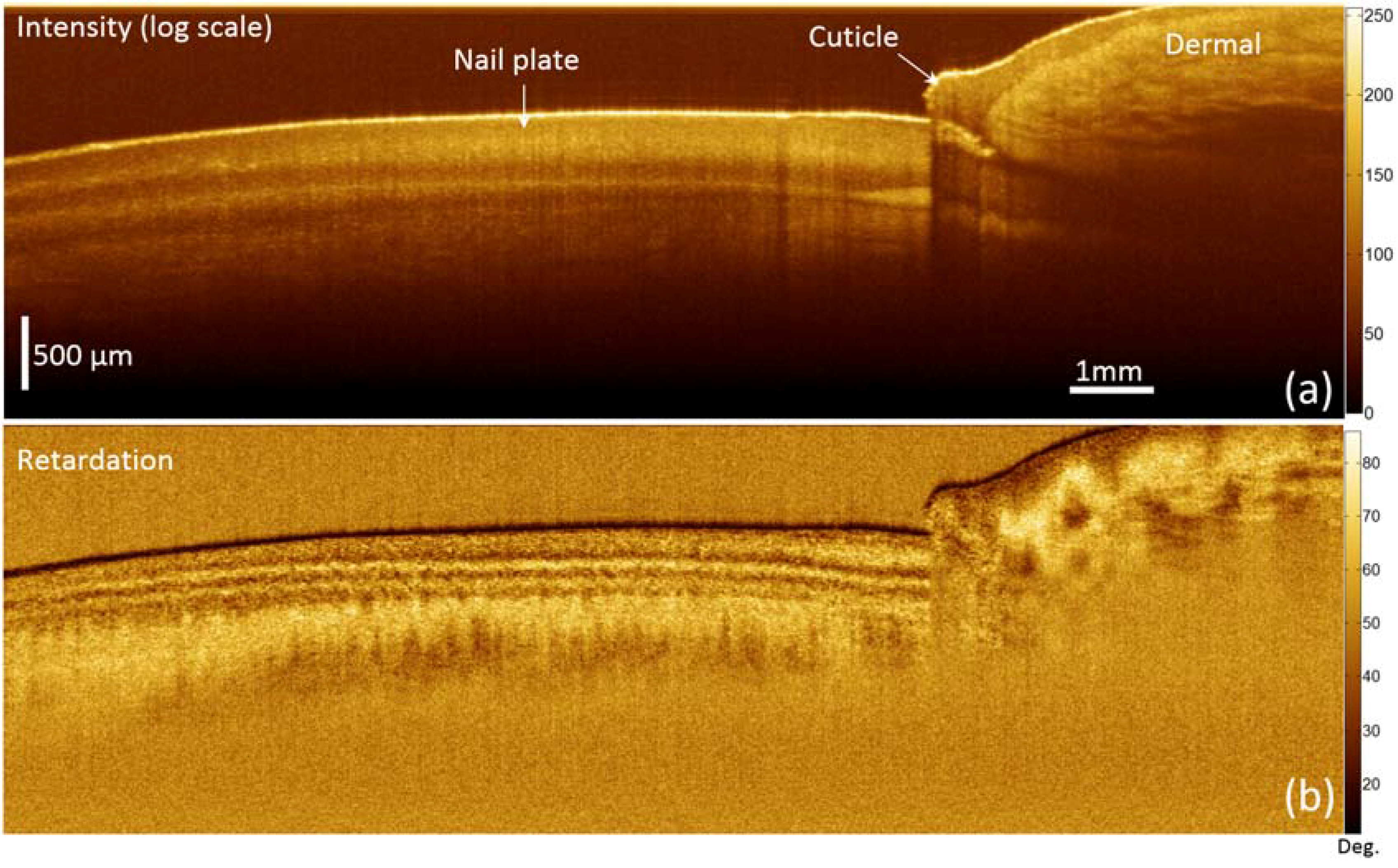
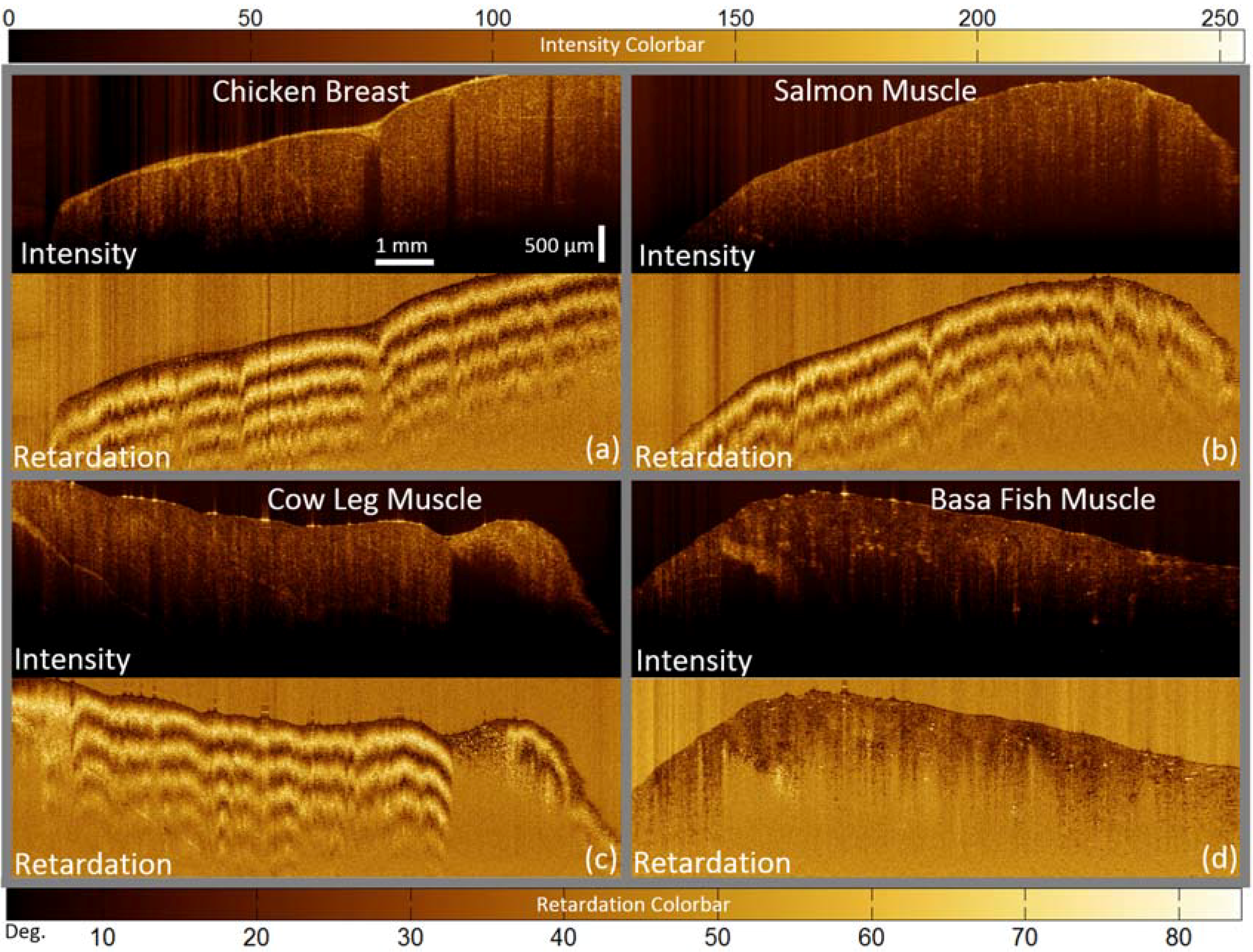
3. Results and Discussion

To verify the performance of the PSOCT system we imaged an achromatic quarter-wave plate (RABQ-1600; ThorLabs Inc.). The quarter-wave plate was constructed from two air-spaced multi-order wave plates; one a magnesium fluoride (MgF2) plate and the other a crystal quartz plate; with their optical axes crossed. Figure 2a shows the u and v detected signal amplitudes from the QWP averaged over 100 A-scans (CHu in blue and CHv in red). Clearly seen are Fresnel reflections from the air-MgF2; MgF2-air; air-quartz; and quartz-air interfaces from left to right; respectively. The expected polarization states of the reflections from the top and bottom surfaces of the quarter-wave plate can be obtained by inserting ΓS = 0 and π/2 in Equation (6); resulting in an x-polarized reflection from the top surface and a y-polarized reflection from the bottom surface regardless of the optical axis orientation of the QWP. The u-detection channel has a large peak at the far left corresponding to top surface reflection and the v-detection channel has a large peak at the far right corresponding to the bottom surface reflection; consistent with the expected polarization states at the detectors for the top surface (x-polarized) and the bottom surface (y-polarized) reflections. The small peaks near the peaks corresponding to the surface interfaces in Figure 2a are ghost images created by multiple reflections.
Figure 2b shows the (single-pass) retardation of the quarter-wave plate measured from the OCT signal amplitudes of the u- and v-detection channels at the four surface interfaces. The retardation experienced by the reflection from the top surface (air-MgF2) must be zero. However, the measured retardation value is slightly above zero. As in this PSOCT system the retardation is measured only by the amplitudes of the two OCT polarization channels and is independent of their phase relation, negative phase differences cannot be measured and the retardation is always a positive value. Also, crosstalk between the two polarization channels, imperfect separation of the two polarization channels by the PBSs, and imperfect circular polarized light incident on the quarter-wave plate can create a very small, but non-zero, peak in CHu corresponding to the reflection from the top surface (Air-MgF2), as is apparent in Figure 2a. This results in a non-zero retardation value. Correspondingly, the retardation experienced by the reflection from the bottom surface (quartz-air) must be 90°. However, as double-pass retardations 180° + θ are mapped to 180° − θ [28], the single pass retardation values are all slightly below 90°. The retardations experienced by the two surface interfaces in the middle of the quarter-wave plate (MgF2-air and air-quartz) are equal as expected since the quartz and MgF2 plates are air-spaced (note that the CHu peak corresponding to air-quartz interface is large compared to the other peaks and lies outside of the vertical axis range in Figure 2a).
Figure 2. PSOCT imaging of a quarter-wave plate; Measured OCT signal amplitudes (CHu and CHv) (a) and the retardation (b) of an achromatic quarter-wave plate; (c) change in the retardation with axial depth, and (d) change in the retardation with the orientation of the achromatic quarter-wave plate optic axis.
Photonics 01 00283 g002
To evaluate the change in the retardation measurement with respect to the axial depth, we measured retardation experienced by reflection from the top surface of the quarter-wave plate at different axial positions. Figure 2c shows that the retardation remains within ±2° for all axial depths (the mean value is 7.43°). To validate that the retardation measurements are insensitive to the sample orientation, we measured the retardation of a quarter-wave plate with its orientation changing from 0° to 90° in 15° steps. Illustrated in Figure 2d, the retardation was measured to be 80.75° ± 3.5°. As this PSOCT system uses circularly polarized light, it is insensitive to the sample’s optical axis orientation.
Figure 3 shows the results of PSOCT imaging of fingernail in vivo with the proposed system. Different birefringence of the nail plate compared to the adjacent tissue is apparent, consistent with the results reported in [19,35]. Figure 4 shows the results of PSOCT imaging of chicken breast, salmon, cow leg, and basa fish muscle ex vivo samples. Unlike the basa fish muscle, the chicken breast, salmon, and cow leg muscle samples showed fairly strong birefringence. Note that the cow leg sample (Figure 4c) includes fat at the far right of the sample with a different appearance compared to the adjacent muscle. This part does not show any birefringence in the retardation image as expected due to the amorphous nature of fat. Five frames were averaged in the images presented in Figure 3 and Figure 4.
Figure 3. PSOCT imaging of fingernail; Intensity (a) and retardation (b).
Photonics 01 00283 g003
Using current pricing, this fiber optic PDD implementation costs significantly cheaper than that of an analogous PDD scheme made with bulk optical components and mounts from a major optomechanical parts supplier. Reduced cost, ease of use, and compactness are key advantages of this PDD scheme. It is noteworthy that the PSOCT system presented in this work requires circularly polarized incident light for measuring quantitatively correct retardation of the sample and deviations from circularly polarized illumination results in less accurate quantitative results. Therefore, all SM fibers need to be fixed to the optical breadboard to ensure stable polarization states throughout the system. This restriction is mitigated in PSOCT systems implemented based solely on PM fiber. Also, the system presented in this work cannot be used for endoscopic imaging with spinning SM fiber catheters since the polarization state of the incident light is continuously varying as the spinning SM fiber catheter is flexing and in motion. However, this restriction is not associated with the presented PDD scheme and can be removed using incident light with multiple (not necessarily known) polarization states [17,18,19,20,21,22,23,24,25,26].
Figure 4. PSOCT imaging of muscle samples; Intensity and retardation of (a) chicken breast, (b) salmon, (c) cow leg, and (d) basa fish muscle samples.
Photonics 01 00283 g004

4. Conclusions

This paper presents a new balanced fiber-based polarization diversity detection scheme for PSOCT imaging. This scheme employs a custom polarization independent 50/50 combiner with SM fiber inputs and PM fiber outputs. The advantages of this scheme include easier alignment, lower cost, and easier miniaturization compared to designs with bulk optics polarization-sensitive detection. Also, unlike the PM fiber-based systems that have PM fiber inputs to the combiner, the SM fiber lengths do not have to be accurately matched. PM fiber on the combiner outputs maintain defined polarization states for balanced detection. We demonstrated this detection scheme in a benchtop galvanometer scanned PSOCT system with circularly polarized incident light. Imaging and birefringence values of fingernail in vivo, chicken breast, salmon, basa fish, and cow leg muscle ex vivo were presented.

Acknowledgments

This work was supported by operating grants from the Natural Sciences and Engineering Research Council of Canada (NSERC) and the Canadian Institutes of Health Research (CIHR), and a Postdoctoral Fellowship awarded to HP from NSERC, the Michael Smith Foundation for Health Research (MSFHR), and Lotte & John Hecht Memorial Foundation.

Author Contributions

HP and AL were responsible for the design of the PSOCT system. HP was responsible for the implementation, test, and data analysis. The manuscript was written mainly by HP with significant contributions by AL and PL and with edits done by SL, CM, and LC. HP, PL and CM were responsible for the funding of the project.

Conflict of Interest

The authors declare no conflict of interest.

References

  1. Huang, D.; Swanson, E.A.; Lin, C.P.; Schuman, J.S.; Stinson, W.G.; Chang, W.; Hee, M.R.; Flotte, T.; Gregory, K.; Puliafito, C.A.; et al. Optical coherence tomography. Science 1991, 254, 1178–1181. [Google Scholar] [PubMed]
  2. Fujimoto, J.G.; Brezinski, M.E.; Tearney, G.J.; Boppart, S.A.; Bouma, B.; Hee, M.R.; Southern, J.F.; Swanson, E.A. Optical biopsy and imaging using optical coherence tomography. Nat. Med. 1995, 1, 970–971. [Google Scholar] [CrossRef] [PubMed]
  3. Tearney, G.J.; Brezinski, M.E.; Bouma, B.E.; Boppart, S.A.; Pitris, C.; Southern, J.F.; Fujimoto, J.G. In vivo endoscopic optical biopsy with optical coherence tomography. Science 1997, 276, 2037–2039. [Google Scholar] [PubMed]
  4. Park, B.H.; Saxer, C.; Srinivas, S.M.; Nelson, J.S. In vivo burn depth determination by high-speed fiber-based polarization sensitive optical coherence tomography. J. Biomed. Opt. 2001, 6, 474–479. [Google Scholar] [CrossRef] [PubMed]
  5. Nadkarni, S.K.; Pierce, M.C.; Park, B.H.; de Boer, J.F.; Whittaker, P.; Bouma, B.E.; Bressner, J.E.; Halpern, E.; Houser, S.L.; Tearney, G.J. Measurement of collagen and smooth muscle cell content in atherosclerotic plaques using polarization-sensitive optical coherence tomography. J. Am. Coll. Cardiol. 2007, 49, 1474–1481. [Google Scholar] [CrossRef] [PubMed]
  6. Burns, J.A.; Kim, K.H.; de Boer, J.F.; Anderson, R.R.; Zeitels, S.M. Polarization-sensitive optical coherence tomography imaging of benign and malignant laryngeal lesions: An in vivo study. Otolaryngol Head Neck Surg. 2011, 145, 91–99. [Google Scholar]
  7. Braaf, B.; Vermeer, K.A.; de Groot, M.; Vienola, K.V.; de Boer, J.F. Fiber-based polarization-sensitive OCT of human retina with correction of system polarization distortions. Biomed. Opt. Express 2014, 5, 2736–2758. [Google Scholar] [PubMed]
  8. Zotter, S.; Pircher, M.; Torzicky, T.; Baumann, B.; Yoshida, H.; Hirose, F.; Roberts, P.; Ritter, M.; Schütze, C.; Götzinger, E.; et al. Large-field high-speed polarization sensitive spectral domain OCT and its applications in ophthalmology. Biomed. Opt. Express 2012, 3, 2720–2732. [Google Scholar] [PubMed]
  9. Hee, M.R.; Huang, D.; Swanson, E.; Fujimoto, J.G. Polarization-sensitive low-coherence reflectometer for birefringence characterization and ranging. J. Opt. Am. B 1992, 9, 903–908. [Google Scholar]
  10. de Boer, J.F.; Milner, T.E.; Van Gemert, M.J.C.; Nelson, J.S. Two-dimensional birefringence imaging in biological tissue by polarization-sensitive optical coherence tomography. Opt. Lett. 1997, 22, 934–936. [Google Scholar] [PubMed]
  11. de Boer, J.F.; Srinivas, S.M.; Malekafzali, A.; Chen, Z.; Nelson, J.S. Imaging thermally damaged tissue by polarization sensitive optical coherence tomography. Opt. Express 1998, 3, 212–218. [Google Scholar] [PubMed]
  12. Everett, M.J.; Schoenenberger, K.; Colston, B.W., Jr.; Da Silva, L.B. Birefringence characterization of biological tissue by use of optical coherence tomography. Opt. Lett. 1998, 23, 228–230. [Google Scholar] [PubMed]
  13. de Boer, J.F.; Milner, T.E.; Nelson, J.S. Determination of the depth-resolved Stokes parameters of the light backscattered from turbid media by use of the polarization-sensitive optical coherence tomography. Opt. Lett. 1999, 24, 300–302. [Google Scholar] [PubMed]
  14. Hitzenberger, C.K.; Gӧtzinger, E.; Sticker, M.; Pircher, M.; Fercher, A.F. Measurement and imaging of birefringence and optic axis orientation by phase resolved polarization sensitive optical coherence tomography. Opt. Express 2001, 9, 780–790. [Google Scholar] [PubMed]
  15. Yao, G.; Wang, V. Two-dimensional depth-resolved Muller matrix characterization of biological tissue by optical coherence tomography. Opt. Lett. 1999, 24, 537–539. [Google Scholar] [PubMed]
  16. Jiao, S.; Yao, G.; Wang, L.V. Depth-resolved two-dimensional Stokes vectors of backscattered light and Mueller matrices of biological tissue measured with optical coherence tomography. Appl. Opt. 2000, 39, 6318–6324. [Google Scholar] [PubMed]
  17. Saxer, C.E.; de Boer, J.F.; Park, B.H.; Zhao, Y.; Chen, Z.; Nelson, J.S. High-speed fiber-based polarization-sensitive optical coherence tomography of in vivo human skin. Opt. Lett. 2000, 25, 1355–1357. [Google Scholar] [CrossRef] [PubMed]
  18. Pierce, M.C.; Park, B.H.; Cense, B.; de Boer, J.F. Simultaneous intensity, birefringence, and flow measurements with high-speed fiber-based optical coherence tomography. Opt. Lett. 2002, 27, 1534–1536. [Google Scholar] [PubMed]
  19. Park, B.H.; Pierce, M.C.; Cense, B.; de Boer, J.F. Real-time multi-functional optical coherence tomography. Opt. Express 2003, 11, 782–793. [Google Scholar] [CrossRef] [PubMed]
  20. Park, B.H.; Pierce, M.C.; Cense, B.; de Boer, J.F. Jones matrix analysis for a polarization-sensitive optical coherence tomography system using fiber-optic components. Opt. Lett. 2004, 29, 2512–2514. [Google Scholar] [CrossRef] [PubMed]
  21. Yamanari, M.; Makita, S.; Yasuno, Y. Polarization-sensitive swept-source optical coherence tomography with continuous source polarization modulation. Opt. Express 2008, 16, 5892–5906. [Google Scholar] [PubMed]
  22. Villinger, M.; Zhang, E.Z.; Nadkarni, S.K.; Oh, W.Y.; Vakoc, B.J.; Bouma, B.E. Spectral binning for mitigation of polarization mode dispersion artifacts in catheter-based optical frequency domain imaging. Opt. Express 2013, 21, 16353–16369. [Google Scholar] [PubMed]
  23. Kim, K.H.; Park, B.H.; Tu, Y.; Hasan, T.; Lee, B.; Li, J.; de Boer, J.F. Polarization-sensitive optical frequency domain imaging based on unpolarized light. Opt. Express 2011, 19, 552–561. [Google Scholar] [PubMed]
  24. Oh, W.Y.; Yun, S.H.; Vakoc, B.J.; Shishkov, M.; Desjardins, A.E.; Park, B.H.; de Boer, J.F.; Tearney, G.J.; Bouma, B.E. High-speed polarization sensitive optical frequency domain imaging with frequency multiplexing. Opt. Express 2008, 16, 1096–1103. [Google Scholar] [PubMed]
  25. Baumann, B.; Choi, W.J.; Potsaid, B.; Huang, D.; Duker, J.S.; Fujimoto, J.G. Swept-source/Fourier domain polarization sensitive optical coherence tomography with a passive polarization delay unit. Opt. Express 2012, 20, 10229–10241. [Google Scholar]
  26. Ju, M.J.; Hong, Y.J.; Makita, S.; Lim, Y.; Kurokawa, K.; Duan, L.; Miura, M.; Tang, S.; Yasuno, Y. Advanced multicontrast Jones matrix optical coherence tomography for Doppler and polarization sensitive imaging. Opt. Express 2013, 21, 19412–19436. [Google Scholar] [PubMed]
  27. Rollins, M.; Izatt, J.A. Optimal interferometer designs for optical coherence tomography. Opt. Lett. 1999, 24, 1484–1486. [Google Scholar] [PubMed]
  28. Pierce, M.; Shishkov, M.; Park, B.H.; Nassif, N.A.; Bouma, B.E.; Tearney, G.J.; de Boer, J.F. Effects of sample arm motion in the endoscopic polarization-sensitive optical coherence tomography. Opt. Express 2005, 13, 5739–5749. [Google Scholar] [PubMed]
  29. Fu, X.; Wang, Z.; Wang, H.; Wang, Y.T.; Jenkins, M.W.; Rollins, A.M. Fiber-optic catheter-based polarization-sensitive OCT for radio-frequency ablation monitoring. Opt. Lett. 2014, 38, 5066–5069. [Google Scholar]
  30. Wang, Z.; Lee, H.C.; Ahsen, O.O.; Lee, B.K.; Choi, W.J.; Potsaid, B.; Liu, J.; Jayaraman, V.; Cable, A.; Kraus, M.F.; et al. Depth-encoded all-fiber swept-source polarization sensitive OCT. Biomed. Opt. Express 2014, 5, 2931–2949. [Google Scholar]
  31. Lin, H.; Kao, M.C.; Lai, C.M.; Huang, J.C.; Kuo, W.C. All fiber optics circular-state swept source polarization-sensitive optical coherence tomography. J. Biomed. Opt. 2013, 19, 021110. [Google Scholar]
  32. Davé, D.P.; Akkin, T.; Milner, T.E. Polarization-maintaining fiber-based optical low-coherence reflectometer for characterization and ranging of birefringence. Opt. Lett. 2003, 28, 1775–1777. [Google Scholar] [PubMed]
  33. Al-Qaisi, M.K.; Akkin, T. Polarization-sensitive optical coherence tomography based on polarization-maintaining fibers and frequency multiplexing. Opt. Express 2008, 16, 13032–13041. [Google Scholar] [PubMed]
  34. Gӧtzinger, E.; Baumann, B.; Pircher, M.; Hitzenberger, C.K. Polarization maintaining fiber based ultra-high resolution spectral domain polarization sensitive optical coherence tomography. Opt. Express 2009, 17, 22704–22717. [Google Scholar] [PubMed]
  35. Bonesi, M.; Sattmann, H.; Torzicky, T.; Zotter, S.; Baumann, B.; Pircher, M.; Gӧtzinger, E.; Eigenwillig, C.; Wieser, W.; Huber, R.; Hitzenberger, C.K. High-speed polarization sensitive optical coherence tomography scan engine based on Fourier domain mode locked laser. Biomed. Opt. Express 2012, 3, 2987–3000. [Google Scholar] [PubMed]
  36. Lu, Z.; Kasaragod, D.; Matcher, S.J. Conical scan polarization-sensitive optical coherence tomography. Biomed. Opt. Express 2014, 5, 763–773. [Google Scholar] [PubMed]
  37. Yun, S.H.; Tearney, G.J.; Vadoc, B.J.; Shishkov, M.; Oh, W.Y.; Desjardins, A.E.; Suter, M.J.; Chan, R.C.; Evans, J.A.; Jang, I.K.; et al. Comprehensive volumetric optical microscopy in vivo. Nat. Med. 2006, 12, 1429–1433. [Google Scholar] [PubMed]
  38. Lee, A.M.D.; Pahlevaninezhad, H.; Yang, V.X.D.; Lam, S.; MacAulay, C.; Lane, P.M. Fiber-based polarization diversity detection for rotary probe optical coherence tomography. Opt. Lett. 2014, 39, 3638–3641. [Google Scholar] [PubMed]
  39. Yun, S.H.; Boudoux, C.; Tearney, G.J.; Bouma, B.E. High-speed wavelength-swept semiconductor laser with a polygon-scanner-based wavelength filter. Opt. Lett. 2003, 28, 1981–1983. [Google Scholar] [CrossRef] [PubMed]
  40. Schoenenbeger, K.; Colston, B.W.; Maitland, D.J., Jr.; Da Silva, L.B.; Everett, M.J. Mapping of birefringence and thermal damage in tissue by use of polarization-sensitive optical coherence tomography. Appl. Opt. 1998, 37, 6026–6036. [Google Scholar] [PubMed]
  41. Yariv, A.; Yeh, P. Photonics: Optical electronics and modern communications, 6th ed.; Oxford University Press: New York, NY, USA; pp. 51–53.

