
Review of New Approaches for Fouling Mitigation in Membrane Separation Processes in Water Treatment Applications


1
Chemistry Department, Faculty of Science, Alexandria University, Alexandria 21526, Egypt
2
Department of Chemistry, College of Science, Qassim University, Buraydah 51452, Qassim, Saudi Arabia
3
Arab Academy for Science, Technology and Maritime Transport, Alexandria 1029, Egypt
*
Author to whom correspondence should be addressed.
Separations 2022, 9(1), 1; https://doi.org/10.3390/separations9010001
Submission received: 19 November 2021
/
Revised: 13 December 2021
/
Accepted: 16 December 2021
/
Published: 21 December 2021
(This article belongs to the Special Issue Advances in Novel Polymeric Membranes and Membrane Process)
Abstract
:This review investigates antifouling agents used in the process of membrane separation (MS), in reverse osmosis (RO), ultrafiltration (UF), nanofiltration (NF), microfiltration (MF), membrane distillation (MD), and membrane bioreactors (MBR), and clarifies the fouling mechanism. Membrane fouling is an incomplete substance formed on the membrane surface, which will quickly reduce the permeation flux and damage the membrane. Foulant is colloidal matter: organic matter (humic acid, protein, carbohydrate, nano/microplastics), inorganic matter (clay such as potassium montmorillonite, silica salt, metal oxide, etc.), and biological matter (viruses, bacteria and microorganisms adhering to the surface of the membrane in the case of nutrients) The stability and performance of the tested nanometric membranes, as well as the mitigation of pollution assisted by electricity and the cleaning and repair of membranes, are reported. Physical, chemical, physico-chemical, and biological methods for cleaning membranes. Biologically induced biofilm dispersion effectively controls fouling. Dynamic changes in membrane foulants during long-term operation are critical to the development and implementation of fouling control methods. Membrane fouling control strategies show that improving membrane performance is not only the end goal, but new ideas and new technologies for membrane cleaning and repair need to be explored and developed in order to develop future applications.
1. Introduction
According to United Nations International Children’s Emergency Fund (UNICEF) reports, over 740 million people worldwide do not have adequate safe water supply, while over 2.5 billion people have access to combined water supply [1]. Traditional water treatment technologies were developed primarily to reduce the risks of waterborne diseases by removing or chemically inactivating viruses, bacteria, and protozoa [2]. Technologies for desalinating seawater and removing contaminants from polluted water bodies are among the advanced water treatment processes [3]. Membrane-based processes, advanced oxidation, and adsorption on activated carbon and other substrates are examples of advanced water treatment processes.
Since 1960, membrane-based technologies have been used in water purification and desalination [4]. Membrane water treatment is a method of removing undesirable constituents from water. A membrane is an imperfect barrier that allows some substances to pass through while blocking others. Water treatment facilities clean surface water, groundwater, and wastewater using various membranes and processes to produce clean water for industry and drinking [5]. The pressure gradient, chemical potential, temperature, or current flux used to pass liquids, gases, particulates, molecules, and ions is the driving force behind membrane technologies. The concentration gradient of chemical potential is used as the driving force in dialysis and forward osmosis. Membrane desalination is a temperature-driven membrane process. Water desalination is currently best accomplished through reverse osmosis or electrochemical treatment methods.
Membrane fouling is the deposition and accumulation of organic, inorganic, and biological substances on the membrane surface, which results in the formation of a fouling layer with resistance to hydraulic flow or a loss of membrane performance [6,7]. Fouling occurs when the convective transport of foulants from the feed solution to the membrane surface outweighs the back-diffusion of foulants from the membrane surface back to the bulk solution [8]. Fouling not only increases hydraulic resistance, but it also causes the formation of a cake layer with significant cake-enhanced concentration polarization (CECP) effects, the formation of a cake layer that blocks membrane pores, or a combination of these effects. In the literature, several potential membrane foulants have been identified and reported. Silica colloids, latex colloids, sodium alginate, colloidal aluminum oxide, humic acid, bovine serum albumin (BSA), fatty acids, surfactants, natural organic matters (NOM), and cellulose are among them [9,10]. These macromolecules enter the feed solution due to unregulated disposal. Several factors contribute to foulant deposition and attachment on the membrane surface, which promotes foulant deposition and attachment. The discussion of membrane fouling entails investigating the factors that influence membrane fouling.
The following factors contribute significantly to membrane fouling [11]: (i) feed chemistry and composition, i.e., pH, ionic strength, and foulant concentration; (ii) Concentration polarization (CP) is broadly defined as the deposition of rejected solutes on the membrane’s surface, resulting in the polarized layer, a region near the membrane with spatially varying concentrations. This increased resistance raises the osmotic pressure across the membrane, lowering the driving force of the process (TMP), permeate flux, and observed solute rejection, all of which increase the possibility of membrane failure [12,13]; (iii) Membrane material type, porosity, hydrophobicity, surface charges, membrane morphology, and membrane molecular weight cut-off (MWCO) are all examples of membrane properties; (iv) Temperature, pressure, aeration, permeate flux, and several other hydrodynamic conditions are examples of process operating conditions.
Pressure is used as a common driving force for membrane separation [14]. Depending on the pore size and operating mechanisms, pressure-driven membranes can be classified as MF, UF, NF, and RO (Figure 1) [15].
Complete pore blocking, partial pore blocking, internal pore blocking, and cake formation are the four types of fouling mechanisms identified by Hermia [17] that can occur in membrane processes. Because more than one type of fouling can occur simultaneously in a process, the chemical nature of the foulants (e.g., organic, inorganic, or biological) must be known in order to inhibit or at least control such mechanisms [18]. Beyond the classification, the pollutant’s nature can provide an overview of the type of fouling and its impact on membrane properties. Adsorption, accumulation, or precipitation, for example, can occur on the surface or within the pores of the membrane. This can affect the membrane’s separation performance, such as permeate flux and membrane selectivity, as well as membrane lifetime [19,20].
The buildup, deposition, and/or adsorption of foulants on the surface and/or pores of a pressure-driven membrane results in membrane deterioration, permeation flux, solute removal efficiency, and TMP drop [12]. The fouling mechanism of low-pressure MF and UF membranes differs from that of high-pressure NF and RO membranes. Adsorption in the pore and obstruction are more prevalent in MF and UF membranes, whereas surface foulants are more common in NF and RO membranes due to the more dense and non-porous features of RO membranes. Surface fouling is less “hazardous” than interior RO membrane fouling. It is more reversible and may be readily regulated by increasing feedwater fluid dynamics or chemical cleaning. Surface and interior fouling, however, may be permanent depending on the composition of the entering water and the interaction with the membrane [12]. Figure 2 presents scanning electron microscopy (SEM) image of different types of membrane fouling.
Scale is the precipitated inorganic crystals of Ca2+, Mg2+, CO32−, SO42−, and PO46− ions. Scale formation involves complex crystallization mechanisms and transport processes. In the pressure-driven desalination process, when the ion solubility limit is exceeded, the concentration of the dissolved salt increases 4 to 10 times, resulting in crystallization [21,22]. The ions from the supersaturated solution crystallize at the surface of the film by surface crystallization and bulk crystallization [23]. The former is simply due to lateral scale growth (the mechanism of crystal growth due to heterogeneous nucleation is a complicated process and depends on the interfacial energy at the interfaces in the system and the surface morphology, in detail in reference [24]), which is more common under high operating pressure and low cross flow velocity. The latter is the uniform growth of particles in the mass phase at high pressure and moderate cross flow velocity. Figure 3 shows a schematic diagram of the key steps in the formation of scale on the surface of the RO membrane.
Biological fouling (biofouling) is caused by the adhesion of live microorganisms to the membrane surface from the feed water. These microorganisms rapidly grow to form a biofilm at the expense of nutrients in the feed. Unlike silica fouling and colloidal fouling, which mainly occur on specific elements in RO facilities, biological fouling occurs at any stage of the desalination process, mainly resulting in the fouling of the RO membrane [26,27]. Organic fouling combines the deposition, reaction, and interaction of high-molecular-weight organic molecules, such as natural organic matter (NOM) and/or transparent exopolymer particles (TEP), with the membrane surface. Due to the degradation and decomposition of living organisms, NOMs, for example, fulvic acid and humic acid, exist in seawater. TEPs are mainly composed of long-chain polymers of amino sugars or mucopolysaccharides, which are derived from organic substrates released by aquatic organisms. Dissolved organic matter (DOM) TEP can occur through biological and non-biological pathways [28]. In the biological pathway, TEPs are produced by microorganisms through the shedding of the mucosal/cellular lining, while in the non-biological pathway, TEPs are formed from precursors in a specific aquatic environment. In surface seawater, the number of TEP with a particle size of approximately 0.4 to 200 µm can reach 4000 TEP/mL [29].
To ensure the long-term operating sustainability of membrane filtering systems, regular physical and chemical cleanings, as well as various methods of membrane fouling management, are used during operation [30]. Those fouling control measures, on the other hand, will lead to increased process complexity and, as a result, operational costs. Membrane fouling can be characterized as reversible or irreversible depending on the foulant cleanability. Reversible fouling may be addressed with basic physical cleanings (e.g., water flushing, air sparging, and backwashing), but irreversible fouling needs chemical cleaning [31,32].
Because membrane fouling is unavoidable, effective tactics and approaches are required to mitigate its negative effects. As a result, many researchers are focusing their efforts on creating effective membrane fouling management strategies. Modifying membrane surface characteristics [33,34], improving operating parameters [35,36], and providing feed pre-treatment [37] are the most frequent ways for membrane fouling management.
In this review article, we have discussed the fouling problems in the membrane technology for use in water and wastewater treatment. This review contains an overview of various factors affecting membrane fouling and several approaches to overcome this problem.
2. Strategies for Mitigation of Fouling
2.1. Pressure Driven Membrane Processes
Depending on the water supply, fouling in RO systems include (i) particulate/colloidal fouling, (ii) scaling, (iii) organic fouling, and (iv) biofouling. Autopsies revealed that the fouling kinds and processes differed between seawater RO (SWRO) and wastewater RO (WWRO). SWRO and WWRO (lead and terminal modules) autopsies were done after five and three months of operation, respectively. The fouling layers were subjected to ultrastructural, chemical, and microbiological examinations. The WWRO train exhibited mostly bio/organic fouling at the lead position element and mostly inorganic fouling at the terminal position element, whereas the SWRO train contained bio/organic fouling at both end position elements. In the case of WWRO membranes, Betaproteobacteria were the most abundant colonizing species, with Ca, S, and P being the most abundant inorganic elements. Alpha and Gammaproteobacteria dominated the microbial community of SWRO membranes. Ca, Fe, and S were the most common inorganic components found in the fouling layer of SWRO membranes [38,39]. Small-size colloidal solids cause colloidal fouling. Larger colloids are not greatly shown by dynamic fluid elevation effects for crossflow speed profiles near the membrane surface. Colloidal dirt, clay, iron oxide, silica particles, proteins, polysaccharides, organic polymers, bacteria, nano/microplastics [40,41], and viruses (bio-colloids) [42,43] have a range of size from 1 to 1000 nm. However, there are no well-defined limits [44], Colloidal fouling in RO is studied widely as it is summarized by two review articles [44,45].
Inorganic scale is a mineral precipitate on the surface of the membrane. In the case of a salt-rejecting membrane system, as used for NF and RO, the concentration of dissolved mineral salt increased 4–10 times according to the conditions of operation and efficiency of the membrane [46] both cause CP of on the surface of the membrane. When the salinity concentration exceeds its solubility limit, they can be crystallized on a scale of formation of the membrane surface. The most common component of the scale in the RO application is CaCO3, CaSO4, Ca3(PO4)2, BaSO4, and silicates [21]. A deca-forming mechanism, its pattern and morphology have been reported [47,48,49,50]. Control strategies include chemical products [50,51] or physical disposal methods [52]. The type of scale and the suppression of scale formation have been reported [53,54].
Organic fouling is the most difficult to remove during the pre-treatment stage. Together with the desalination plant in the Mediterranean Sea, a pilot study of a seawater pretreatment system for desalination by RO has been carried out [55]. Although better seawater quality is achieved by advanced membrane treatment, neither membrane nor conventional pretreatment can guarantee the complete removal of NOM in feed. Organic matter is always present in the RO feed [56]: (i) NOM’s natural; (ii) algae organic matter (AOM) composed of extracellular and intracellular macromolecules [57]; (iii) wastewater effluent organic matter (EfOM), determined by the background composition of NOM and soluble microbial products (SMPs) of biological wastewater treatment. NOM is one of the most important organic matters that causes RO fouling. Most of the NOM that exists on the surface, groundwater, and seawater is composed of humic substances [58,59]. The complex macromolecular products of chemical and biological degradation of animal and plant residues affect water quality and act as inorganic ion complexing agents [58].
Biological fouling: Unlike the other three forms of fouling, which can be managed by lowering the foulant concentration in the feedwater, biofouling is difficult to regulate simply by lowering the quantity of microorganisms in the feedwater [60]. Bacteria are everywhere and may easily attach, collect, and proliferate in a membrane system, even if their numbers are initially low. When bacteria cling and develop on RO systems, they produce a biofilm, which is a gel-like coating with a dense bacterial concentration and extracellular polymeric molecules [61]. Biofouling is one of the most problematic types of fouling in RO systems, accounting for more than 50% of the deposits removed from the membrane surface during autopsy studies [38,62]. Determining the biofouling tendency of the feed water prior to the RO system is essential in reducing the nutrient content.
Chen et al. [63] examined the feasibility of using the retentate RO of the municipal water recovery plant from two aspects: (a) the fouling tendency of the RO retentate membrane and (b) the effectiveness of the anti-fouling strategy. The membrane used is an internal selective thin film composite polyethersulfone hollow fiber membrane (TFC/PES) membrane with high water permeability and good mechanical strength. Phosphate fouling is possible inorganic scale on the innermost layer of PES membrane, while silica fouling is the main scale on the outermost surface of the membrane. Two anti-fouling pretreatments, namely pH adjustment and anti-fouling pretreatment of the feed stream, are both simple and effective. Using RO retentate with pH 7.2 as the feed and 1 M NaCl as the draw solution, the average power density at 20 bar was 7.3 W/m2. By using HCl to modify the initial pH value of the RO retentate to 5.5, the average power density was increased to 12.6 W/m2, and by adding 1.1 mM ethylenediaminetetraacetic acid (EDTA), to 13.4 W/m2. Without specified pretreatment, the flow recovery rate of the fouled membrane washed with deionized water (DI) reached 84.9%, and it was air-bubbled for 30 min at a high crossflow velocity of 23.3 cm/s (Re = 2497) to reach 95.0% After minutes of pretreatment with pH adjustment, the flux recovery rate was increased to 94.6% after washing with DI, and the flux recovery rate was increased to 100.0% after bubbling. After the pretreatment by adding 1.1 mM EDTA to the RO retentate, the flux was almost completely restored by physical cleaning with DI and bubbling air. It is important to develop effective pretreatments by pH adjustment or by adding EDTA before RO and physical cleaning methods for membranes that generate osmotic energy by cleaning with DI and air jets. Figure 4 shows SEM-EDX and XPS images of the outer surface of the layer of fouled membrane at different retentate pH and pretreated with 1 mM EDTA.
Using state-of-the-art TFC/PES hollow fiber membranes for osmotic power production, the power density and fouling tendency of RO retentate from a municipal water recycling facility were investigated. The fouling of RO retentate by phosphate salts and silica resulted in considerable decreases in water flow and power density. In PRO testing, the average power density of the first two batches was only 7.3 W/m2 when utilizing the original RO retentate at pH 7.2 as the feed and 1 M NaCl as the draw solution at 20 bar. The scaling caused by phosphate salts was reduced by lowering the pH level as a consequence of employing the modified RO retentate with a starting pH of 5.5; the average power density was raised to 12.6 W/m2. At 1000 min, the ultimate pH level was 6.8, which was appropriate for disposal. The addition of 1.1 mM anti-scaling EDTA to RO retentate can prevent phosphate salt scaling and delay silica fouling. As a result, the mean power density was increased to 13.4 W/m2. Without chemical cleaning, the fouled membrane utilizing the original RO retentate as the feed solution had a cleaning efficiency of 84.9% by DI water flushing and 95.0% by air bubbling for 30 min after the PRO test at a high crossflow velocity of 23.3 cm/s (Re = 2497). Cleaning efficiencies were increased by 94.6% by DI water flushing and 100% by air bubbling when the initial pH value of RO retentate was lowered to 5.5. If the RO retentate was pre-treated with 1.1 mM EDTA, any cleaning technique could achieve 100% flux recovery. EDTA dose optimization and research into additional anti-scalants to minimize the fouling proclivity of RO retentate and phosphorus reduction should also be addressed. Figure 4 presents the SEM-EDX and XPS images of the outer surface of the layer of fouled membrane with the treatment conditions [63].
Zhang et al. [64] found that, in water reuse plants, pretreatment prior to RO systems prevents fast fouling. Secondary effluent may have a high suspended-solids load, as well as a high proportion of colloidal particles, organic compounds, and bacteria at times. If such components are not effectively removed during pretreatment, they might cause the permanent fouling of downstream RO systems. A pretreatment combination of advanced oxidation (ozonation), ceramic MF, and biological activated carbon (BAC) was evaluated to reduce RO membrane organic fouling. In comparison to MF and BAC, or ozone + MF, the fouling generated by the feed wastewater processed by the combination of ozonation + ceramic MF and BAC is readily eliminated by DI flushing.
Figure 5 shows the surface morphology of the RO membrane after filtration using different Selfs Point pretreatment feed water. All membranes are cleaned with DI and filtered for about 1 h. Figure 5a shows that deionized water cleaning does not affect membranes exposed to untreated secondary effluent. Although the flux reduction rate of RO membranes with different pretreatment feeds is similar, the membrane surface after DI cleaning is quite different. In Figure 5b, the surface of the RO membrane used as a raw material for BAC pretreatment is still almost completely covered by scale. The membranes that use ozone and ozone + MF to pretreat wastewater (Figure 5c,d) are partially cleaned. However, combined ozone + MF pretreatment shows better performance than ozone pretreatment alone. In the latter case, the dirt is still trapped in the gaps of the two membranes. After a simple DI cleaning, the membrane contaminated by the ozone + MF ceramic +BAC pretreatment feed was almost completely recovered. Using ozone + ceramic MF + BAC to pretreat the feed, frequent RO permeation cleaning can reduce the CIP frequency of the RO membrane. Different RO feed pretreatments were tested to find a viable technology that would minimize the contamination of RO membranes used in remote areas, thus reducing the consumption of cleaning chemicals.
An ozone + ceramic + BAC membrane provides the best protection for the RO membrane. Any foulant in the water after this pretreatment combination can be easily removed from the RO membrane surface with DI. If DI is used frequently for cleaning, chemical cleaning may be reduced. Ozone combines with an MF ceramic membrane to effectively oxidize organic matter. With the ozone remaining in the test, the organic contaminants on the MF ceramic membrane appeared to be partially dissolved. Although BAC can effectively remove DOC from treated water, the retention rate of DOC from the RO membrane has also decreased. The BAC effluent must be pre-filtered to reduce bioorganic matter entering the RO system [64]. Membrane fouling will affect membrane performance and can occur with any type of water supply and membrane type. Scale can even be found in the secondary RO device that handles the RO permeate. The initial impact of the contamination is moderate, and the acceleration is relatively fast. If it is not resolved in time, the performance decrease will not be obvious.
The following steps are involved in the correction of fouling conditions: early detection of the fouling process, identification of fouling conditions and their mitigation, and correction of membrane performance. The cleaning operation sequence involves flushing the RO train with permeate water, connecting the train or train segment to the cleaning unit, producing a cleaning solution in the cleaning unit, and recirculating the cleaning solution through the RO train for 1–4 h.
Direct osmosis is a common phenomenon in RO systems that treat high-salinity feed water. When a RO unit is turned off, permeate flows back through the membrane to the feed side. It is used in a novel cleaning technique known as direct osmosis–high salinity (DO–HS) membrane performance restoration. While the RO unit is running, the DO—HS technique is to inject a high-salinity solution into the suction of a high-pressure pump. The injection lasts for a few seconds. From the feed to the concentration, the high pulse passes via the membrane components. The flow across the membrane is reversed during the flow of a high-salinity wave via the feed channels of RO components. The foulants are lifted from the membrane surface by the reverse permeate flow. The continuous feed of concentrate flow sweeps removes foulant particles from the membrane components and transports them away from the membrane unit (Figure 6). This approach of restoring membrane function is particularly successful in controlling membrane biofouling and removing colloidal deposits [65].
In chemistry, it is oxidized and halogenated with chlorine (Cl2). Oxidants such as chlorine are added to the RO feed stream as water disinfectants and bactericides to control the biological fouling of the direct media filtration system [67]. Even if the influent water is dechlorinated before the membrane system, there will still be exposure to very low concentrations of residual Cl2 [68]. Chlorine in the form of hypochlorous acid (HOCl) and hypochlorite ions (OCl−) attacks the dense layer on top of the poly amide (PA), replaces the hydrogen atoms in the amide nitrogen, and then undergoes cyclic chlorination through Orton’s intermolecular rearrangement, resulting in the appearance of chlorination [69], as shown in Figure 7.
In addition to vulnerable amide nitrogen, the terminal NH2 group in the PA chain is chlorine-sensitive and -reactive and oxidizes and decomposes into secondary and tertiary amine bonds in contact with Cl2 [70]. Therefore, the degradation of the PA layer leads to the loss of membrane integrity and ultimately increases membrane flux and salt passage. Delamination between the PA layer and the support layer is the main reason for performance degradation and ultimately shortens the life of the RO membrane. Various parameters of the water supply, such as pH value, temperature, chlorine concentration, and contact time, will affect the rate of chlorine erosion [71]. Fouling and treatment methods on different membranes will be clarified.
In NF, the pretreatment with coupled aluminum (Al) EC-MF reduces the colloid and organic fouling in the NF process of inland natural brackish surface water. The removal of NOM from EC is improved due to the following reasons: compared with the minimum solubility of Al (pH 5.5 vs. 6.2), the extensive protonation of NOM at a weakly acidic constant pH during electrolysis; the use of a medium current density (10 mA/cm2) adequate contact time during electrolysis and flocculation; the combined charge neutralization and scanning solidification through increases in the Al dosage. FTIR spectroscopy provides direct evidence that, compared with MF alone, EC-MF removes the hydrophobic part and part of the hydrophilic residues of NOM. The flow curve of NF using EC-MF to pretreat natural brine is almost the same as the flow curve of a model solution with similar ionic composition, but no NOM added, indicating that the effect of organic fouling is negligible. XPS showed that there was a trace of CaCO3 precipitation after EC-MF pretreatment, which was confirmed by electron microscopy, which caused only a slight decrease in flux. Finally, NF achieves excellent strontium removal, as well as other divalent ions and NOM. EC improves the elimination of NOM by lowering the pH of the condensate, increasing the contact time between the coagulant and NOM and (pH 5.5, 10 mA/cm2 current density, and 25 mg Al/L dose). Due to the chloride-assisted pitting corrosion, the high salt content of the influent leads to the dissolution of ultra-Faraday aluminum, and the high sulfate concentration and high applied current density further aggravate this pitting corrosion.
Compared to the MF-only pretreatment, the EC-MF pretreatment has better control of NF fouling due to the additional removal of parts of hydrophilic NOM (i.e., polysaccharides and amides), hydrophobic NOM, and nanocolloids, and a high Donnan effect rejects SO42−, Ca2+, Mg2+ and Sr+2 ions, while the monovalent Na+ and Cl− ions are poorly blocked by the NF membrane. These points and some implications of membrane and EC process operation/optimization have been clarified. DOC removal is enhanced by EC at a pH value slightly below the minimum solubility of aluminum (i.e., 5.5 vs. 6.2), which removed a portion of the hydrophilic fraction in addition to the typical hydrophobic and higher-molecular-weight NOM fractions similar to enhanced conventional chemical coagulation. Therefore, in addition to the better control of NF contamination, this also reduces the formation of disinfection by-products, because the hydrophilic NOM component is also used as a precursor of trihalomethane and haloacetic acid. By using a high current density for brackish water, an increasingly shorter residence time can be designed in the EC unit, which will correspondingly reduce the frequency of NOM hydrogen bubble collision and NOM removal, which results in a suboptimal implementation. For aluminum, similar to iron, a current density of 10 mA/cm2 is recommended to maximize NOM control and minimize electrolysis time. Electron micrographs of the above mentioned membranes are shown in Figure 8 [72].
Ohno et al. [73] studied the influence of coagulant residues on NF membrane fouling, laboratory-scale MF-NF and MF-NF pilot plant configuration. In lab-scale experiments, NF feedwater is pretreated with polyaluminum chloride (PACl) or alum before using MF. When the aluminum content of the feed water is greater than or equal to 18 μg/L, the permeability of the NF membrane decreases, but it does not decrease when the aluminum content is less than 9 μg/L. After pretreatment with FeCl3, the permeability of the NF membrane did not decrease significantly; residual iron did not affect permeability. When SiO2 was added to water prior to pretreatment with PACl, the permeability of the membrane decreased at approximately twice the rate. Thermodynamic calculations and elemental analysis of fouling recovered from the membrane show that most inorganic fouling compounds are composed of aluminum, silicate, and possibly potassium. In the pilot plant, the NF feed is pretreated with PACl. The transmembrane pressure of NF doubled in 4.5 months of operation. Although the concentration of Al in the NF feed is not high (30 μg/L), analysis of the membrane contaminants shows that the excessive accumulation of Al and silicate indicates that Al residues cause the aluminosilicate or Al(OH)3 fouling of the membrane. In the pilot-scale MF-NF factory experiment and laboratory-scale MF-NF experiment, when aluminum coagulant is used in the pretreatment process, the residual aluminum in the NF feed water is greatly increased, measured by the permeability of the membrane. In laboratory-scale experiments using FeCl3 as a coagulant, the permeability of the NF membrane did not decrease significantly. In the laboratory-scale Al coagulant experiment, when the influent contains 18 μg/L or more of residual Al, the permeability of the NF membrane decreases, but not when the Al concentration is less than about 9 μg/L. The control of residual aluminum during NF pretreatment is essential to reduce severe fouling. The silicate concentration in the NF feed water greatly increases fouling, and other cations, especially potassium, can be incorporated into the foulants in the form of zeolite [73].
Xiong et al. [74] planned the layer-by-layer (LbL) self-assembly of positively-charged PEI and GA and NO-CMC alternately on the PES membrane surfaces, resulting in a new surface-modified NF membrane. The modification was intended to improve membrane separation performance. The AgNPs were coated on the modified membrane in two distinct ways as shown in (Figure 9) to improve the antibiological fouling performance of the NF membrane. To evaluate the produced membrane surface chemical composition and shape, FTIR, XRD, SEM, AFM, zeta potential, and water contact angle measurements were used. The modified membrane rejected different single nonheavy metal salts in the following order: MgCl2 > MgSO4 > CaCl2 > Na2CO3 > NaCl > Na2SO4. Furthermore, the rejection rates of single heavy metal salts Cr3+, Cu2+, Cd2+, and Ni2+ were 88.95%, 84.04%, 82.69%, and 83.47%, respectively. The results indicated that the (PEI@GA/NO-CMC)1.5/PES membrane performed well in terms of separation from nonheavy metal salts and heavy metal salts due to Donnan exclusion and steric hindrance. The resulting (PEI@GA-Ag/NO-CMC)1.5/PES membrane and (PEI@GA/NOCMC)1.5-Ag/PES membrane had a high antibiological fouling ability when AgNPs were loaded on the modified membrane in two distinct ways. At the same time, the antibacterial property of the (PEI@GA/NO-CMC)1.5-Ag/PES membrane was superior to that of the (PEI@GA/NO-CMC)1.5/PES membrane, indicating that (PEI@GA/NO-CMC)1.5/PES membrane had a higher capability for ameliorating antibiological fouling. To summarize, the produced NF membranes show a high potential for use in sewage treatment applications.
Purushothaman et al. [75] built an NF membrane using n-ZnO integrated PEES membranes. XRD-, AT-FTIR-, AFM-, and SEM-coupled EDX analyses were used to characterize the produced membranes. To study the effect of n-ZnO on membrane characteristics, pure water flow, contact angle, MWCO, mean pore size, and porosity were measured. The characterization revealed an asymmetric membrane structure following n-ZnO insertion. This addition improved the hydrophilicity of the PEES membrane. The model foulant HA was used to evaluate the fouling-resistant capability of the membranes, and an improved anti-fouling irreversible property with a matching flux recovery rate of 92.43% was discovered for the prepared membrane. Because of the hydrophilic nature of ZnO particles, the rejection performance and permeability of HA were 98.03% and 166.73 l m−2 h−1, respectively at a constant transmembrane pressure (1380 KPa). Furthermore, the modified PEES membrane outperformed the standard PEES membrane in terms of separation performance for monovalent and divalent anions. The PEES/n-ZnO hybrid membrane helped NF in a successful method for improving membrane performance and anti-fouling property, indicating its vast use in water reclamation.
Yadav et al. [76] described a new kind of PSf/GO-vanillin NF membranes that are extremely permeable, selective, and fouling resistant. The membranes are made up of two-dimensional GO layers embedded with vanillin as a pyrogen and PSf as the foundation polymer. There is increasing interest in studying the synergistic effect of GO and vanillin on membrane permeability and antifouling properties. Detailed physicochemical and morphological studies were carried out using a variety of spectroscopic and microscopic methods. For 2000 ppm MgSO4 and NaCl solutions, the improved PSf16/GO0.15-vanillin 0.8 membrane exhibited 92.5% and 25.4% rejection rates, respectively. The antifouling results indicated that BSA was rejected at a rate of over 99% and that FRR was rejected at a rate of 93.57%. The antifouling properties of the developed membranes for treating landfill leachate wastewater were tested experimentally. The findings indicated 84–90% rejection for Mg+2 and Ca+2 with a FRR of 90.32. The experiment showed that adding GO and vanillin to the polymeric matrix increases fouling resistance and membrane performance considerably. Future studies will concentrate on molecular sieving for industrial separations and other specialized applications utilizing mixed matrix membranes.
A dynamic membrane (DM) is a layer of particles deposited on a conventional membrane by permeate drag, and the deposited particles serve as a secondary membrane [77,78]. The rejected ingredients of the feed are generally produced into a cake, which is also called a DM if it improves permeate quality [79]. DMs can be divided into two types based on whether the DM is composed of feed constituents deposited during filtration or intentionally pre-deposited particles with desired properties on the primary membrane (PM) [77], namely (1) self-formed DMs, in which solid particles from wastewater form the DM and aid in improving permeate quality [80], and (2) DMs generated by the deposition of materials such as metallic compounds (particularly oxides), polymers, activated carbon, soil-based compounds, and nanoparticles on meshes or UF, MF, NF, or RO membranes. Based on their content, DMs have been divided into eight categories: metal oxides (e.g., hydrous Zr(IV) oxide, HAOPs), polymers (e.g., PAA, PVA), soil-based (e.g., kaolin, diatomite), other metallic (e.g., AlCl3, FeCl3, CaCO3), activated carbon (e.g., PAC, GAC), nanoparticles (e.g., CNTs, CNFs), dual or hybrid (e.g., hydrous Zr(IV) oxide-PAA, HAOPs-PAC), and others e.g., AER, ovalbumin). The presence of DMs, which operate as an adsorbing, protecting layer against foulants, aids in the reduction of PM fouling. Figure 10 depicts a schematic describing how DMs minimize fouling by displaying the deposition of DM, the saturation of DM by foulants, and eventually the removal of the DM.
2.2. Low Pressure-Driven Membranes
The quantification and identification of relevant parameters in emerging fields is related to biofouling and preventing UF seawater membrane biofouling in membrane systems for seawater desalination [10]. Yu et al. [82] studied the effects of pH and surface charge on membrane fouling in addition to the effects of pre-ozonation during the processing of representative surface water samples (Hyde Park Recreation Lake). Although biopolymers in surface water can be removed by UF membranes, the removal rate of lower MW NOM is very low, confirming the importance of membrane pore size. For the NF membrane, the removal of the smaller MW fraction (800 Da−10 kDa) is lower than expected due to its pore size; however, for all MW distributions (over 90%), almost all humic hydrophobic substances can pass through the hydrophilic NF membrane removal. The charge and hydrophilicity of NOM is a controlling factor. Hydrophilic NF membrane can remove hydrophobic organic matter but not hydrophilic matter. An increased loading effect (more negative zeta potential) and solution pH improve organic matter removal and reduce fouling (flux decrease), most likely through greater repulsive force on the membrane surface. The pre-ozonation of surface water increases the hydrophilic part and the anionic charge of NOM and changes its size distribution, resulting in less UF contamination and smaller-pore NF (less flux reduction), but the NF contamination of larger pores increased slightly. The difference in the behavior of the NF is related to the relative size of the ozonated organic components and the pores of the NF; similarly sized ozonated organic parts and NF pores can cause the significant fouling of the membrane [82]. The surface of the hydrophobic membrane can be transformed into a hydrophilic substance by (i) coating in a coating solution and (ii) the grafting (immobilization) of hydrophilic substances on its surface from grafting solutions [82,83]. Light-induced grafting functionalizes the membrane surface, provides low-cost process operations, selectively absorbs ultraviolet rays without affecting the bulk polymer, mild reaction conditions, and permanent membrane surface changes and easy chemical control [84,85,86,87].
Membrane fouling will reduce permeate flux and membrane productivity, significantly reduce membrane life, increase feed pressure, and power requirements, and increase membrane maintenance and replacement costs. Qasim et al. [88] researched different fouling mitigation strategies. Ultrasound is an effective technique that can be used for scale control and membrane cleaning. It is an effective means to increase the flow rate and clean the membrane, because it has the unique ability to produce special chemical and physical effects, which can remove the scale on the membrane surface. However, this application cannot have a significant impact on pore clogging and is limited to external fouling. Although ultrasound is effective in improving flow and cleaning membranes, it has some serious limitations, including large-scale applications, lack of suitable transducers, and lack of economic feasibility data [89]. The influence of ultrasound on membrane degradation is discussed, as well as the efficacy of this application for membranes other than the flat-sheet type and an economic analysis of ultrasound-assisted membrane processes. Figure 11 shows a microscopic image of the PES (100 kDa) membrane surface after being sonicated.
Backpulsing: In the literature, backpulsing is also referred to as backshocking [90,91], high-frequency retro filtration [92,93], and transmembrane pressure pulsing [94,95]. Backpulsing is defined by three main parameters: amplitude, duration, and frequency. The absolute value of the negative TMP during each backpulse is defined as amplitude. Each pulse’s duration is measured in milliseconds. The inverse of the sum of backpulsing duration and forward filtering time is frequency [96]. It denotes the time between two successive pulses. Backpulsing volume, which is the amount of clean water utilized for each backpulse, is also of interest. Figure 12 depicts the decrease in membrane permeability in the filtration process with and without backpulsing or backwashing.
The performance of backpulsing on membrane cleaning is depicted in Figure 13. Backpulsing removes hydraulically reversible fouling and reduces concentration polarization (Figure 13). External fouling and non-adhesive fouling are examples of hydraulically reversible fouling [98]. The mechanisms of fouling generation are used to classify external and internal fouling [99]. Fouling induced by pore constriction or pore obstruction is usually exterior fouling, whereas fouling caused by cake formation is usually internal fouling. Fouling is classified as non-adhesive or adhesive depending on the types of fouling compounds [11]. Particulate and inorganic fouling are often non-adhesive, but biofouling, colloidal, and organic fouling are typically adhesive.
Despite the fact that experiments show that backpulsing is effective at reducing concentration polarization and preventing membrane fouling, backpulsing cleaning efficiency is determined by several factors, including:
- Feeding characteristics. The types of foulants present in the feed solution have a direct impact on the types of membrane fouling. Backpulsing is more effective at removing non-adhesive and external fouling. The higher the concentration of foulants, the more severe the fouling of the membrane and the lower the cleaning efficiency of backpulsing.
- Membrane characteristics. Because of the elasticity of polymeric membranes, the cleaning capability of backpulsing may be caused by membrane vibration caused by the rapid reverses of TMP rather than reverse flow. Membrane surface modification can alter the types of fouling formation, making backpulsing more effective. Furthermore, membrane pore sizes are related to membrane fouling types and backpulsing efficiency.
- The operational parameters. It is critical to perform backpulsing under optimal conditions, such as amplitude, duration, and frequency. It is also advantageous to investigate the three backpulsing parameters as a backpulsing strategy. In addition, the traditional filtration parameters are TMP/flux and CFV [97].
The hydrophilic and anti-fouling PSf membrane is made by the in-situ cross-linking polymerization of AA and vinyltriethoxy (VETOS) in a polysulfone (PSf) solution and non-solvent induced phase separation. The modified doping solution with increased P (AAVETOS) concentration showed increased viscosity and decreased precipitation rate, resulting in morphological changes, from an elongated finger-like macroporous morphology to a completely sponge-like structure. When compared to a neat PSf membrane, the as-cast modified membranes had higher hydrophilicity and electronegativity, which inhibited protein adsorption and improved antifouling. Because of the cross-linked polymer networks, the modified PSf membranes have good long-term stability in hot water and mechanical properties. As a result of in situ cross-linked polymerization, a simple and universal method for modifying PSf membranes with high hydrophilicity and antifouling on a large scale has been developed [100].
Even in the absence of filtration, MF fouling is caused by macro solute or particle adsorption due to specific intermolecular interactions between the particles and the membrane. Because of hydrophobic interactions, hydrogen bonding, Van der Waals attractions, and extracellular macromolecular interactions, it is irreversible, and the foulants are usually adhesive. The UF fouling is a non-adhesive fouling caused by reversible filtration-induced macro solute or particle deposition, in which cells, cell debris, and other rejected particles accumulate on the top membrane surface. It manifests itself as external fouling or cake formation. In this respect, reversible fouling is caused by cake formation and is less dependent on membrane surface chemistry than irreversible fouling [101,102].
Ma et al. [103] reported that, while UF membranes can reportedly remove algae effectively, the removal process can cause serious fouling. A moderate pre-oxidation method (KMnO4Fe (II) process) is used to avoid the adverse effects of algae cells destroyed by oxidants, in order to achieve a balance between intracellular organic matter release and increased algae removal. The performance of the KMnO4Fe (II) pretreatment UF membrane after long-term operation in the presence of algae reservoir water shows that algae is almost completely removed, that the dirt is obviously reduced, and that the overall performance is far better than Fe(III) coagulation. The transmembrane pressure (TMP) in the Fe (III) condensation process increased to 42 kPa; however, the TMP in the KMnO4Fe (II) process only increased to 25.1 kPa after 90 days. The slower transmembrane pressure is attributed to the larger floc size, higher surface activity, and algae inactivation. Although it has little effect on the development of microorganisms, due to the release of extracellular polymers, the microbial abundance (20.7%) observed during the KMnO4Fe (II) process is lower than during the solidification alone (44.9%). The floc layer is easily washed off, and many original membrane pores can be clearly seen.
The effluent water quality is excellent, especially its turbidity, chromaticity, and Mn and Fe concentration. Based on the excellent performance of UF membranes, the KMnO4-Fe(II) process is applied to the water treatment of algae-containing water. Teixeira et al. [104] found that seasonal changes in the NOM content of natural surface waters in Algarve, Portugal, affect UF performance. A 47 k Da MWCO plate-and-frame polysulfone membrane can be used to evaluate the use of natural water (clean water, 35 NTU and turbid water, 33–34.6 NTU) at acidic, neutral, and alkaline pH values for seasonal pollution control on a laboratory scale pH adjustment. PH value adjustment controls seasonal UF pollution: when the water has less NOM (in dry periods, clear water), acidity will improve UF performance, and, during heavy rains (cloudy water with high NOM concentration), an alkaline pH value can minimize pollution. According to the effect of the electric charge on the size of the membrane, this behavior is explained for clear water. For cloudy water, the electrostatic repulsion between the membrane surface and NOM and turbid particles decreases at pH 4.13. The protonation of NOM functional groups reduces the hydrodynamic radius of humus and increases its hydrophobicity and adsorption tendency. At pH 4.13, a dense layer of scale will form, and the flux will be less than at pH 8.33. The observed decrease in raw water feed concentration and decrease in WRR rejection rate confirm that moderately hard water cations enhance extensive membrane adsorption. For pure water and clear water, as the pH value increases, the pores of the polysulfone membrane become more negatively charged because preferential anion adsorption reduces the membrane pore size, which reduces flux, and the rejection rate increases. The use of a PSf membrane to adjust the pH value can help seasonally control UF fouling. For clear water with low NOM content (during the Algarve’s dry season), acidity increases the yield to UF, while during and after heavy rains (turbid water with high NOM concentration), alkaline pH will be beneficial.
The effect of the ultrasonic cleaning of PTFE MF membranes contaminated with a premixed humic acid bentonite mixture was studied [105]. Figure 14 depicts the set-up for dead-end MF membranes cleaning by ultrasonication. Chemical coagulation prior to MF increased the turbidity and TSS removal rate by 9.5% and 11.4%, respectively. The experimental data fitted to the constant pressure filtration model determined the order of the following main fouling mechanisms: (i) limited resistance of the membrane, (ii) limited resistance to clogging of the pores, and (iii) limited resistance to cake formation. When continuous ultrasonic cleaning is performed within 25 min of a 2.0 cm probe distance, the relative permeability of the membrane is 53 and the FRR is 45%. Continuous ultrasonic cleaning at 2.0 cm probe distance, 25 min total cleaning time, 15 mg/L coagulant dose, and 15 W ultrasonic power resulted in relative membrane permeability of 53 and flux recovery of 45 percent. Ultrasonic cleaning is effective in cleaning membranes that have been fouled by cake formation rather than those that have been fouled by pore blocking. The efficacy of this cleaning technique is determined by the intensity and duration of ultrasound irradiation, as well as the location of the cavitation zone in relation to the fouled membrane surface. Furthermore, the pretreatment of NOM-water with iron-based coagulants and clay coagulants improves membrane filterability and facilitates ultrasonic membrane cleaning. In terms of flux recovery, ultrasonic cleaning outperforms hydraulic cleaning. In terms of mitigating NOM-induced fouling, it is a competitive and safer alternative to chemical cleaning.
A supported carbon nanotube/γ alumina UF membrane with built-in de-fouling capacity was constructed, described, and evaluated for its water-purification performance. Coating a carbon nanotube (CNT)/γ-alumina composite layer over a porous PbZr0.52Ti0.48O3 (PZT) piezoelectric substrate results in an asymmetric UF membrane with a pore size of 8 nm. The PZT support not only provides mechanical strength to the membrane, but it may also be utilized to create ultrasound by using an alternating voltage (AV). This, in turn, prevents and/or eliminates fouling during filtration. The conducting composite layer functions as a size-selective membrane as well as an electrode. Membrane constructions having a piezoelectric layer can be triggered with an alternating current electrical field to create ultrasound from inside. This in-situ ultrasonic emission has the potential to be highly successful in preventing or eliminating fouling during water filtration. Because γ-alumina particles efficiently filled the gap between CNTs, the inclusion of -alumina in the membrane structure was very helpful for mechanical durability and pore size reduction. Further multi-layer structure optimization, long-term stability, more environmentally acceptable (lead-free) piezoelectric compositions, scale-up, and use on tubular geometries and cost-effectiveness is needed The schematic presentation of the cross flow membrane module used for membrane operation with in-situ ultrasound generation is shown in Figure 15 [106].
To assess the performance of the membranes, in-house and commercial membranes with varying characteristics were employed for humic acid separation in a circular crossflow filtering system. Seshasayee et al. [107] created the in-house membranes by including bentonite nanoclay in Mendall PVDF, PPSU, PSF, and PES polymers. Because of its capacity to generate membranes with exceptional characteristics, such as mechanical strength, wide surface areas, adsorption, antifouling, and well-defined pore morphology, bentonite nanoclay is considered a promising material for membrane applications. Three different commercial membranes were also employed to remove humic acid from water. The in-house and commercial membranes were then evaluated in terms of morphology, surface roughness, porosity, and average pore size. When compared to other commercial and in-house membranes, the XM50 commercial membranes had smooth and uniform surface topography. The polymeric membranes’ morphological structure, surface roughness, and pore size were altered by the addition of bentonite to the polymer. In a circular crossflow filtering system, pure water flux, permeate flux, and humic acid rejection were evaluated for in-house polymeric membranes and commercial membranes. The addition of bentonite nanoclay to the in-house polymeric membranes was shown to decrease humic acid fouling.
Shen et al. [108] created a hybrid system comprised of several coagulation methods and UF. The properties and effects of flocs produced in various coagulation systems on UF membrane fouling control were studied (Figure 16). Within an appropriate range of NOM content, all three coagulation methods were efficient in increasing membrane flow and lowering membrane resistance as UF pretreatment. The effectiveness of PAC on NOM removal and fouling management was significantly restricted at high starting NOM concentrations. The effect of initial NOM concentration on removing NOM and alleviating membrane fouling was slightly weakened in the PAC-PolyDMDAAC coagulation system, indicating that the composite flocculant PAC-PolyDMDAAC produced larger flocs through a combination of charge neutralization and adsorption bridging. Under both low and high starting NOM concentrations, the combined action of the adsorption-bridging effect, sweeping effect, and charge neutralization were the processes in the PAC + PolyDMDAAC dual-coagulation system. Although the flocs generated in the PAC + PolyDMDAAC dual-coagulation system had a lower recovery ability than those formed in the PAC and PAC-PolyDMDAAC coagulation systems, they did have a better recovery ability than those formed in the PAC and PAC-PolyDMDAAC coagulation systems. In the PAC + PolyDMDAAC dual-coagulation system, flocs produced by adsorption-bridging and sweeping had a large size and a better capacity to withstand shear force, resulting in the development of a cake layer with a porous and fluffy structure and reduced membrane pore obstruction. These findings showed that using a dual coagulation system that combines PAC coagulation and PolyDMDAAC flocculation as a pretreatment for the UF process can improve floc properties and cake layer structure, resulting in improved NOM removal and membrane fouling management.
Du et al. [109] examined the effects of Ca2+ on membrane fouling and TrOCs removal in an electric-field-assisted MF system in the presence of Na+ alone for comparison. In the presence of Na+ at 1.5 V, negatively charged bovine serum albumin (BSA) moved towards the anode, far away from the membrane surface, resulting in a 42.9% TMP decrease. In contrast, due to Ca2+ greater charge shielding, the electrophoretic migration of BSA was restricted, resulting in a negligible influence of the electric field (1.5 V) on membrane fouling. Under 3 V of applied voltage, however, the synergistic effects of electrochemical oxidation and bridging interaction between Ca2+ and BSA promoted the formation of denser settleable flocs and a thinner porous cake layer, alleviating membrane fouling with a 64.5% decrease in TMP and nearly 100% BSA removal (Figure 17). The removal of TrOCs increased with voltage, reaching 29.4–80.4% at 3 V. The electric field might increase the contact time between TrOCs and the strong oxidants produced on the anode, therefore increasing TrOC elimination. The Ca+2 higher charge buffering capacity, on the other hand, diminished the electric field force and hence, reduced TrOCs elimination.
As the most important target of membrane separation, the inadequacy of permeability and anti-fouling frequently limits the application of the membrane in actual oily wastewater [110]. Feng et al. [111] proposed a novel concept of membrane surface construction to mitigate this intractable problem, using SiO2 as the support layer and GO as the isolation layer (Figure 18). The separation performance of the modified membranes for the simulated emulsion indicated the optimal co-localization percentage of the support layer (56 mg/L) and isolation layer (3.5 mg/L). The thin GO layer may efficiently prevent pollutants from entering the membrane pores while maintaining the roughness of the membrane. The GO@SiO2 membrane could successfully perform emulsion purification with a consistent permeability (654.11 LMHB) and excellent separation efficiency due to the synergistic action of the isolation layer and support layer (99.41%). With a permeability recovery rate of 89.75% (low-density oil) and 90.41% (high-density oil) after 10 repeated cycles, the membrane’s outstanding anti-fouling performance assures its long-term cycling stability. Indirectly, the storage stability proves its worth in practical applications. More significantly, the GO@SiO2 membrane has good purification and cycle stability, making it ideal for industrial emulsion treatment (permeability recovery rate of 84.01%).
Ceramic MF/UF membranes have made rapid progress in industrial/municipal wastewater treatment and drinking water treatment in recent decades due to their superior properties to conventional polymeric membranes. Ceramic membranes’ advantageous properties include fouling resistance, high permeability, good recoverability, chemical stability, and long lifetime, which have found applications with recent advancements in both fabrication methods and nanotechnology. As a result, ceramic membranes hold a lot of promise in terms of potential applications in water treatment [11]. Ceramic MF/UF membranes, ceramic nanocomposite membranes, ceramic catalytic membranes, and membrane fouling are the current state of the art in ceramic membranes. Figure 19 summarizes the benefits of ceramic membranes and ceramic nanocomposite membranes in hybrid water treatment systems.
Engineered spacers: Methods for controlling membrane fouling have been documented, including the invention of spacers. A spacer is often necessary to provide a flow route for the feed and permeate, to promote local mixing, and, more recently, to control membrane fouling. By increasing spacer design and geometry, these vital tasks of a spacer might be strengthened [7]. Biofouling has been seen on feed spacers, resulting in considerable axial pressure reduction. Efficient biofouling management requires a combined strategy in which spacer design improvements are applied, and enhanced hydrodynamic conditions provide a less compact biofilm that is simpler to remove [113]. Although simulation studies show that thicker and coated feed spacers might improve biofilm removal [114], other research has determined that changes to spacer geometry and hydrodynamic circumstances result in relatively few improvements in biofouling [115]. One explanation is that, while bactericidal coatings might kill bacteria, the resultant biomass can build a layer that supports bacterial multiplication and, ultimately, biofilm formation. Furthermore, antifouling effects frequently differ in static experiments vs. active filtration, prompting suggestions for revisions in how antibacterial activities are defined [116]. The design of the spacer has been changed to decrease pressure loss, enhance local mixing, induce turbulence, and eliminate dead zones. The use of innovative spacer geometries with decreased stagnation zones, as well as the treatment of the spacer surface with a biocide agent, has been demonstrated to be successful in lowering the tendency towards biofouling. Spacers have been effectively employed in the plate-and-frame module to improve air-bubble distribution in liquid/gas streams, create turbulence, and project air bubbles toward the membrane surface for effective membrane cleaning. This biological approach is still understudied, but it has the potential to be combined with physical (new spacer geometries and turbulence-induced flow, such as two-phase flow processes or black flushing, for example) and chemical (surface modification by polymers or metallic/toxic compounds, for example) approaches. Using computational methods, the approaches may involve a combination of two or more approaches, as well as investigating optimum solutions for certain membrane systems or membrane module shapes. This might result in a comprehensive designed spacer design for fouling management in membrane systems [7].
MBR: The construction and operation of central wastewater treatment plants began in the early twentieth century. With the introduction of rigorous membrane research and development in the mid-twentieth century, an increasing number of wastewater facilities began to include an MBR in their designs. The MBR system, on the other hand, is far from flawless. Membrane systems foul continually, and if fouling occurs for an extended length of time, maintenance and cleaning expenses will grow proportionally. In MATLAB/Simulink, a fouling monitoring and prediction tool was created. The model accepts membrane fouling states and estimates membrane total resistance using deterministic and stochastic models. Using an artificial neural network technique, the tool may forecast future TMP cycles based on previous TMP performance. TMP data were created synthetically using a mathematical model that has been verified. Finally, an artificial neural network controller is used to keep temperature and MLSS within their intended ranges. The controller can reduce disturbances in both modes in a small range around their intended setpoints [117].
To enhance the economic and environmental operations of wastewater treatment facilities, optimal operational techniques have been widely used. Inadequate optimization systems, on the other hand, have been used in membrane bioreactor (MBR) plants, resulting in excessive energy consumption owing to unpredictable influent coupled with complicated biological and physical interactions connected with membrane fouling. They use process simulation to create a dual-objective optimization system based on the harmony search method. Among competing models, a bidirectional gated recurrent unit generated the most accurate forecasts of changing fluctuations in hourly influent, and the projected influent data was utilized to recommend operational methods. Using the combined biological and physical model, the optimization system looked for predicted operating methods such as aeration intensities and permeation-cleaning periods. When the permeation-cleaning time was optimized, the indicated aeration intensities were employed for scouring air on membrane surfaces. When compared to a manually run system, a prototype MBR plant outfitted with the recommended optimization system improved energy efficiency by 4% and reduced fouling by 39%. Dual-objective optimization also proved viability and dependability in a full-scale MBR plant, increasing energy efficiency by 12% and lowering fouling by 26% (Figure 20) [118].
Li et al. [119] investigated a hybrid system of anaerobic-anoxic-oxic membrane bioreactor (A2O-MBR) and worm reactor (WR). The membrane filtration cycle in A2O-MBR-WR was prolonged by 66.7% due to the interaction between WR and A2O-MBR, as well as microaerobic treatment and worm predation in WR. Membrane rejection of soluble and colloidal foulants (SCF) in the combination system was reduced by 26.0% when compared to conventional A2O-MBR, which may be ascribed to SCF’s increased biodegradability and higher bacterial activity in the combined system. Although sludge disintegration and worm predation in WR reduced floc size in A2O-MBR, alterations in floc surface characteristics might mitigate this detrimental effect on fouling. The interaction energy between sludge flocs and the clean/fouled membrane based on extended Derjaguin-Landau-Verwey-Overbeek (XDLVO) theory was used to investigate the complex effects of sludge flocs on membrane fouling (Figure 21). According to the energy barriers, flocs in A2O-MBR-WR were harder to attach to the membrane and were more likely to detach. Furthermore, high-throughput sequencing research indicated that the microbial community of the cake layer in the combined system was more even and had a larger proportion of bacteria involved in foulant breakdown, which was advantageous for fouling mitigation. The combination of A2O-MBR and WR has demonstrated substantial benefits in the prevention of membrane fouling.
For decades, in-situ fouling management techniques for MBR have been constantly explored and may be broadly classified as biological and physicochemical approaches. However, the processes and performance of these approaches, as well as the possibilities for their use, have not been extensively addressed and compared in a systematic manner. Liu et al. [120] conducted a review of different in situ biological and physicochemical fouling control techniques in terms of fouling control performance, fouling reduction processes, and practicability. This includes a comparison of popular biological control strategies such as quorum quenching (QQ) and physicochemical approaches such as NaClO backflushing, hybrid electrochemical MBR, and anti-biofouling membrane development, as well as an examination of their potential, existing issues, and feasibility in full-scale applications. Future research should focus on creating more sustainable and broadly applicable MBR fouling reduction methods.
To cure industrial liquor condensate, a new anaerobic baffled biofilm-membrane bioreactor (AnBB-MBR) was created. At the same operational hydraulic retention duration of three days, three alternative reactor designs of R1, no media (anaerobic baffled MBR), R2: FF (fixed film AnBB-MBR), and R3: FF + MVB (fixed film and moving bed AnBB-MBR), were tested to reduce membrane fouling, Figure 22. The ceramic membranes’ specific fouling rates were 0.98, 0.84, and 0.5 kPa/L/m2 for R1: no media, R2: FF, and R3: FF + MVB, respectively. Due to biomass retention in the fixed film and the mechanical scouring of the MVB, the R2: FF and R3: FF + MVB reactors reduced membrane fouling rates by 14.1% and 48.9%, respectively, as compared to R1: no media. According to the microbial community study, the biofilm had greater relative abundances of Methanosaeta, but the suspended sludge had more Methanobacterium. Furthermore, greater humic and fulvic chemical accumulations in the system may impede methanogenic activity [121].
Photocatalysis is an efficient and ecologically beneficial method of decomposing organic contaminants, especially when sunlight is available as an energy source [122,123]. Opportunities to use materials and technologies from photocatalytic pollutant degradation on the issue of fouling are emerging. Membrane fouling caused by organic foulants is a common issue for all membrane-based technologies and has a significant negative influence on membrane performance. The application of photocatalysis techniques to membranes offers novel ways for membrane fouling management, which is being pursued by an increasing number of researchers. Zhang et al. [124] summarize key developments in photocatalytic materials and methods in water treatment and present recent progress in the development of processes for the photocatalytic alleviation of membrane fouling, including photocatalyst design and modification strategies aimed at improving photocatalytic efficiency, as well as different photocatalysis membrane system configurations (PMS).
Shen et al. [125] discussed the most recent discoveries in polymeric membranes using ZnO nanoparticles for membrane fouling prevention. The review summarizes the reports on PVDF–ZnO composite membranes, PES–ZnO composite membranes, and other composite membranes containing ZnO nanoparticles. The uses of polymer-ZnO membranes are depicted in Figure 23.
2.3. Membrane Fouling Mitigation in Membrane Distillation (MD)
Membrane distillation (MD) is a relatively new technology with enormous promise in water treatment. Despite the fact that there has been a huge lot of study done on MD over the last two decades, the long-term usage of this technique is still limited by membrane fouling [126]. The membrane surface and structure are critical to the MD unit’s performance. In comparison to other membrane processes such as UF and MF, membrane requirements such as macro geometry and microstructure play a larger role in overall process performance [127]. For the MD process application, desirable membranes should be hydrophobic (nonwetting) to allow vapor passage and microporous to allow mass transfer [128]. The pores in the membrane are required to create a vapor flux. The hydrophobicity of the membrane prevents liquid entry into the pores and thus the transfer of the liquid present to the membrane permeate side [129]. Furthermore, certain membrane properties are required to prevent wetting: a small pore diameter, low surface energy on the membrane material, high roughness, a large contact angle, high surface tension of the feed solution in contact with the membrane, and thus a high LEP. The desirable properties of membranes must take into account their interdependence. In MD separation, increasing membrane thickness can increase mechanical strength while decreasing mass transfer. High porosity allows for high permeate fluxes but makes the membrane more susceptible to wetting.
Furthermore, the increase in LEP may be related to a decrease in membrane pore size, which reduces permeate flux. As a result, criteria must be established to ensure effective separation. Table 1 shows the typical values of the desirable properties and their effects on MD applications.
Alkhatib et al. [132] discussed and highlighted new findings on different foulants in the MD process. Furthermore, several fouling processes such as inorganic fouling, organic fouling, biological fouling, and colloidal fouling (Figure 24) were explored to improve the understanding and prevention of membrane fouling. To create a sustainable MD process, different fouling mitigation strategies, such as pre-treatment procedures and cleaning methods (Figure 25) were thoroughly addressed. The advantages and disadvantages of various techniques have been studied and analyzed in order to offer a comprehensive knowledge of fouling reduction in the membrane distillation process. Fouling mitigation methods for various foulants in MD have been proposed (Figure 26).
Membrane modifications break down barriers in terms of the MD process’ operational limitations and explore new possibilities for recovering water from industrial effluents [131]. Water recovery from oily solutions [133], which would cause severe fouling in traditional membranes, becomes possible with modified membranes, such as those containing hydrophilic compounds. Long-term operation is enabled using fluorinated polymers, which also contribute to wetting resistance. The use of inorganic nanoparticles, siloxanes, and perfluoro polymers and GO allows for operation with complex effluents containing surfactant solutions, VOCs, and several inorganic foulants [131].
The exposition time under spinning and the dope solution used in electrospinning of MD membranes allow for the precise control of membrane porosity and thickness. Its design calls for more robust equipment than other techniques like coating [134]. On the other hand, using the dope solution entirely on the membrane surface requires less material to modify. The viscosity of the dope solution determines the drop or spinning formation, which allows the membranes to have a variety of porosities and roughnesses. To initiate chemical reactions between the membrane and the dope solution, the membrane must be pretreated to activate its structure. Electrospun membranes have a high roughness, a high hydrophobicity, a small thickness, and a high porosity.
Coating is the most-researched modification technique for MD membranes, owing to its simple methodology and lack of complex equipment [135,136]. The dip-coating technique, for example, necessitates no additional equipment beyond standard laboratory equipment. It allows for a variety of modifications by varying the solution in which the membrane is immersed. The hydrophobicity of coated membranes was varied by different crosslinks created by grafting. Dip coating with inorganic nanoparticle-containing solutions has the potential to increase membrane porosity. Strongly fluorinated solutions are also used to achieve high LEPs. Vacuum filtration can produce highly homogeneous surfaces, and the sol–gel method can result in significant changes in structure and mechanical strength. However, because of the lack of control over these properties during the experimental procedure, the coating method can have a negative impact on membrane porosity and thickness. Nonetheless, the coating technique appears to be the most feasible for industrial applications because it does not require high temperatures, pressures, or energy to design the process, and it is the simplest fabrication technique among the related techniques.
Because of its greater complexity and the greater robustness of the resulting membranes, plasma treatment has received the least attention in the last five years [137]. Plasma does not require any pretreatments on the membrane surface and is strongly influenced by the exposure time. The membrane modification reactions occur over a short period of time. The use of various gases and attachments to generate radicals on the membrane surface results in a variety of modifications, primarily for more robust and refined separations in MD. Because it facilitates bond formation between the membrane and the modified agent, plasma is an effective strategy for enhancing other modification techniques.
A hybrid ultrasound-assisted DCMD process was designed [138] and the effect of ultrasonic irradiation in mitigating HA membrane fouling during the DCMD process was studied. Although the initial HA concentration does not affect the permeation flux characteristics within the experimental range, ultrasonic irradiation can increase the permeation flux by more than 30% without destroying the HA rejection rate, and all HA permeation concentrations are less than 0.40 mg/L. The higher the concentration factor, the greater the ultrasonic improvement of the obtained permeate flow. The effect of ultrasonic irradiation on a PTFE membrane is shown in Figure 27.
When CaCl2 is added to the HA solution, it can be found that the permeation flux is severely reduced. The presence of Ca+2 will aggravate the organic pollution of HA through charge neutralization, complexation, and the formation of calcium bridges. In the absence of liquid penetrating the membrane pores, HA aggregates spread on the membrane surface to form a thick and dense HA fouling layer, which increases heat-transfer resistance and reduces the pores available for water vaporization. As a result, both permeation flux and thermal efficiency are reduced. Ultrasound brings important mechanical and thermal effects and generates powerful shock waves and micro currents at high speed. The mechanical effect promotes turbulence, reduces boundary layer, and improves color diffusion. Micro-flows, shock waves, and acoustic vortices continuously stimulate the liquid/membrane interface, thereby cooling the interface and reducing HA aggregate deposition. Under ultrasonic irradiation, although some HA contamination spreads over the membrane surface, most of the membrane pores remain open and clean. When the concentration factor reaches 4.0, the relative permeation flux can be kept at approximately 94%. Figure 28 presents morphology images of PTFE membrane after a HA solution concentration experiment under ultrasonic irradiation with different CaCl2 dosage [139].
Hou et al. [140] observed that, due to the formation and deposition of colloidal polysilicic acid on the membrane surface, the permeation flux gradually decreased during the concentration of the silica solution. The hollow fiber PTFE membrane maintains its mechanical properties and initial pore-size distribution under ultrasonic irradiation. Ultrasound provides important mechanical and thermal effects and generates powerful shock waves and high-speed microcurrents. Microflows, shock waves and acoustic vortices continuously stimulate the liquid/membrane interface, effectively keeping the membrane surface clean, and the permeation flux is hardly affected by increasing concentration factors. Even at the beginning of the concentration process, a large amount of silica scale is deposited on the surface of the membrane (Figure 29). Under ultrasonic irradiation, the permeation flux is stable and increased by about 43%; ultrasonic irradiation (Figure 30 andFigure 31) can effectively control the silica scale in the MD process [140].
2.4. Ion Exchange Membrane (IEM)
Environmentally friendly processes are increasingly used in modern industry for demineralization, concentration, product modification, and energy conversion and storage [5,141]. Scale formation due to concentration polarization is a significant impediment in the ED process, particularly on the concentrate side of IEMs [142,143]. However, scale formation in the IEM will significantly reduce the efficiency of the process and increase the cost of the process. The main types of IEM scale, such as colloidal fouling, organic fouling, scale, and biological fouling, are discussed and the main factors affecting scale formation and development are considered. Colloidal fouling: Colloids are undissolved suspended solids that exist in natural water, processed water, and many wastewater streams. They exist in the form of clay minerals, colloidal silica, iron oxide, alumina, manganese oxide, organic colloids, etc. [144,145]. The diameter of the colloidal particles ranges from 10 Å to 1 µm. For example, most of the colloidal particles found in natural water are small aluminum silicate clays. The diameter of these clays ranges from 0.3 to 1.0 microns. The excessive net charge on the surface of the colloid results in the adsorption of ions from the surrounding solution. Figure 32 shows the general model of the colloidal particle electrical double layer [146,147,148]. The solid surface in this model has too much positive charge, which will attract negatively charged molecules from the solution. Since the electrostatic force compensates for most of the excess positive charge, the back layer is closely attached to the solid. The ions in the diffusion layer neutralize the excess charge. The diffusion layer plays a preventive role by preventing colloids from contacting and coagulating [145].
Organic fouling is similar to organic colloidal fouling, except that organic fouling initially dissolves in the ED-treated solution. Compared with ordinary organic molecules that have mainly covalent bonds, the colloidal state of organic molecules is maintained by weak long-range van der Waals attraction and electrostatic repulsion. Organic pollutants are oils, carbohydrates, proteins, aromatics, humic acids, nano/microplastics, and defoamers. These organic substances adhere to the surface of the film and/or remain on the film. This type of membrane fouling is important due to the large number of processed products of different substrates that contain organic matter. There are many different strategies to prevent and control flaking during erectile dysfunction. However, the nature of the dirt must always be considered because some strategies may be applicable to one type of dirt and not be effective for another type of dirt. After that, in emergency systems containing different types of dirt, complex procedures may be involved, including the application of multiple procedures (Figure 33).
Biofouling: The main characteristic of these microbial cells is the presence of special bacteria on the surface of the anode. These bacteria can oxidize biodegradable substrates and produce electrons and protons. The electrons move towards the cathode to complete the electrical circuit. The anode and cathode are separated by CEM and AEM. The life cycle of biofilms is shown in Figure 34, with photomicrographs of various stages of biofilm development. The initial interaction of the bacteria with the surface is reversible (1), and the subsequent adhesion is irreversible (2). After attaching to the surface of the membrane, the bacteria begin to produce and excrete extracellular polymers (2), allowing the cells to adhere to the surface. Continuous growth leads to the development of a microcolony (3). As the size of the microcolonies continues to increase (4), the cells in the microcolonies will experience crowding, reduced nutrient availability, increased excretion of waste products, increased concentrations of toxins and metabolites (including intercellular signaling molecules), and changes in their physical and chemical properties environment. Finally, the matrix is digested in the microcolonies, and the cells move freely through active movement or through browning movement (5). Eventually, a crack forms in the matrix at the edge of the microcolony, through which bacteria can escape into the large amount of surrounding fluid [149]. The types of contamination can involve complex procedures that involve the application of multiple procedures.
When the salt present in the water precipitates and settles on the surface of the membrane and/or its channels, scale will form in the IEM. The main scale ions present in ED-treated solutions include magnesium, calcium, barium, bicarbonate, and sulfate [155,156,157,158,159,160,161,162] When the balance of the solution changes, precipitation occurs, making the solubility lower than the concentration of the salt, causing them to precipitate out of the solution. Generally, there are two main factors that affect precipitation in solution, ion concentration and solution temperature [156,163,164].
IEM’s fouling prevention and control strategy allows fouling to be prevented and controlled during emergencies. However, the nature of fouling should always be kept in mind because a certain strategy may be suitable for one type of foulant but not for another. Subsequently, in the ED system containing different types of fouling, a complicated procedure may be involved, including the application of the following procedures: Many feed solutions for desalination contain foulants, such as organic matter of various molecular weights, suspended solids, and colloids or insoluble salt until saturated. Therefore, the feed solution needs to be pretreated to remove and reduce the concentration level to reduce the possibility of fouling, so as to achieve effective ED operation. Almost all ED systems apply the filtration of the feed solution to remove particles. However, depending on the nature of the feed solution and the water quality of the product, additional procedures such as flocculation, metal hydroxide precipitation, and ion exchange may be required. Hydraulic, mechanical, and chemical cleaning methods are effective scale-control methods, depending on the separation process and module configuration. Chemical cleaning is the most effective CIP procedure during ED operation. Fouling can be controlled by changes in polarity during ED. When an electric field is applied to the feed solution, negatively charged particles or large organic anions migrate to the anion exchange membrane and deposit on the surface membrane. If the polarity is reversed, Figure 35 negatively charged species will migrate from the ion exchange membrane and return to the feed stream. Pulsing the electric field at an optimal frequency can reduce the fouling potential of an already dirty membrane system. It can be understood that the electrical pulse enhances the electrophoretic mobility of the charged particles in the fouling layer near the surface of the membrane, thus reducing fouling potential [153].
Generally, IEM modification aims to change the surface properties of the membrane, such as surface charge, hydrophobic/hydrophilic balance, and roughness. Considering the nature of the dirt, you can choose a cleaning agent to remove dirt from the surface of the IEM or prevent dirt from forming during erectile dysfunction treatment. However, rinsing by adding chemicals can have a negative impact on the performance of the membrane. For example, cleaning the IEM with an alkaline solution can lead to the degradation of the ion exchange groups. Cleaning with an oxidizing agent can cause the degradation of ion exchange groups and the polymer matrix. Also, the addition of some chemicals can have a continuous negative impact on the quality of erectile dysfunction products, which becomes very important when talking about the food industry.
In the development of graphene oxide nanocomposite (GO)/multi-walled carbon nanotube (MWCNT) conductive film to reduce electrical enhancement fouling, the mixed phase inversion method uses graphene oxide (GO) and multi-walled carbon nanotubes (MWCNT) to manufacture conductive films. The influence of the weight ratio of the membrane polymer: solvent and GO: MWCNTs on membrane conductivity was studied. The M10 batch of membranes exhibited moderately high conductivity due to the incorporation of carbon nanomaterials that form a continuous electron path through the membrane matrix. The electric field exerts a stronger repulsive force to repel dirt, thereby reducing the blockage of the membrane surface. Compared with the case of no electric field, the normalized fluxes of M10 (c) −5, M10 (c) −10, and M10 (c) −20 under a continuous electric field are increased by 108.14%, 90.54%, and 89.69%, respectively. A flux of 300 volts/cm. Overall, M10 (c) −5 showed the best performance due to increased conductivity without affecting other membrane properties such as pore size and surface roughness. It was found that the intermittent application of an electric field can achieve fouling mitigation similar to its continuous application [163].
The fouling of APAM towards AEM during the ED of industrial wastewater has recently received attention. Xiang et al. [164] studied the fouling dynamics using several techniques for monitoring the modification of solution and membrane characteristics. The results revealed that conductivity and pH fluctuation are less sensitive than electrochemical signals through TMEP and EIS, concentrating on micro-scale variation at/near the membrane interface. Initially, APAM deposition resulted in minimal current-transfer restrictions, as seen by the TMEP profile’s plateau area. The accumulation of APAM fouling eventually hampered current transmission, resulting in an elevated TMEP due to the development of a gel layer on AEM and/or free volume obstruction. Later, water splitting occurred, as shown by an evident pH difference between the dilute and the concentrate, which may have accelerated fouling by changing the particle size of APAM. The electrochemical properties of the membrane bulk and boundary layer were effectively separated by EIS, suggesting that internal fouling is primarily responsible for the increased membrane resistance (Figure 36). Future research should focus on clarifying the external and internal fouling on IEM and investigating effective fouling mitigation techniques in the ED.
Patil et al. [165] reviewed recent work using carbonaceous conductive membranes for fouling mitigation, contaminant degradation, permeability and selectivity enhancement, highlighting the benefits of carbonaceous conductive membranes in each and highlighting areas that we believe are promising future research directions. Future research should focus on disentangling fouling-reduction processes, overcoming mass transfer constraints and testing more relevant model systems for contaminant degradation, and identifying large-scale application areas that might benefit from permselective capability. A technoeconomic study was carried out for the installation of an electric setup to an example desalination plant. According to the findings, future efforts toward commercialization should focus on increasing fouling reduction from electrification and lowering electrical energy consumption in order to justify the use of conductive carbonaceous membranes in water filtration and separation operations.
It is an urgent challenge to reduce the membrane fouling that is widely occurring in membrane-based water treatment technologies in an effective and long-lasting way. The new electrically assisted membrane coupling technology shows great potential to solve this problem. In the presence of an electric field, it can successfully repel scale, such as natural organic charges, colloids, and bacteria, from the membrane surface, thereby reducing absorption, accumulation, and clogging. More importantly, electric-field-induced microbial inactivation plays an important role in inhibiting the formation of stubborn biofilms (Figure 37). Compared with other membrane fouling control methods such as hydrophilic surface modification, chemical cleaning, and pretreatment optimization, it shows a significant and significant effect. It still has some shortcomings. For example, the production of Joule heat can weaken the mechanical properties of the membrane, and the production of chlorine can produce disinfection by-products that are harmful to the environment. Therefore, corresponding solutions must be implemented. Successful results for reducing electrode biofilm contamination in microbial fuel cells indicate that alternating current may be an ideal choice to avoid the above-mentioned drawbacks. More research can be done to reveal the potential of AC coupled membrane systems and promote wider applications [166].
Pretreatment: Pressure-driven membrane process: By applying the driving membrane process pressure as a pretreatment technique before ED, particles that cause a layer of fouling on the ion exchange membrane or that block the ED stack can be rejected. These filtration technologies use pressure gradients as the driving force and allow separation based on particle size or molecular weight. The general classification distinguishes pressure-driven membrane processes based on pore size and applied pressure, including MF, UF, NF, and RO. Mechanical action: The filtration process involves mechanical procedures (such as ultrasonic, vibration, air bubbles, etc.) to prevent and destroy scale. However, in the ED process, mechanical cleaning is rarely used due to changes in membrane performance or even membrane degradation. Other pretreatment technologies: activated carbon, filtration, particle reactor, ultraviolet radiation, and phytoremediation.
3. Conclusions
This study illustrates the many forms of fouling in various membrane types, as well as the methods of both original treatment and the least-advanced technologies in treatment processes, such as introducing nanochemistry into the area of water treatment. Fouling kinds (inorganic, colloidal, organic, and biological) influence membrane productivity and morphology, resulting in lower flux rates; thus, its mitigation and avoidance are important concerns in water treatment and material science. From a chemical engineering standpoint, the main challenge of membrane modification is to combine the desired property with materials that are economically feasible using more straightforward and effective techniques. Backpulsing has been used in a variety of low-pressure membrane configurations, including flat sheet, tubular, hollow fiber, and spiral-wound membranes. Backpulsing research also encompasses a wide range of industrial fields, including water and wastewater treatment, the food industry, biotechnology applications, and others. The surface ozonation of surface water and membrane modification by coating and grafting decrease flux decline and organic fouling on NF and UF membranes. Flux recovery rose to 94.6% by DI water flushing and 100.0% by air bubbling for RO membrane pre-treatment by pH adjustment. After pretreatment with 1.1 mM EDTA in RO retentate, flux was nearly entirely recovered by physically cleaning with DI water flushing and air bubbling, as well as RO pre-treatment with ozonation. The ceramic membrane and BAC offered the optimum protection for the RO membrane, and the foulant generated from the water prepared by this combination was readily removed from the RO membrane surface by DI. Other techniques, such as pH adjustment, chemical cleaning, and backwashing, have also been considered in order to reduce the effects of CP and foulants’ adsorption affinity towards the membrane surface [167].
Membranes modified using simpler methods, such as coating, will be used to mitigate MD operational problems in large-volume processes, such as desalination or water recovery from industrial discharges. Antifouling properties, resistance in long-term operations, and self-cleaning capability will be required in these cases, which may be achieved through coating. Separations involving high-value-added products that require robust membranes, on the other hand, will gravitate toward more robust techniques, such as electrospinning and plasma, wherein desirable features can be highly controlled and achieved quickly.
New membrane treatment approaches, such as the use of ultrasonic waves, the coupling of applied electric fields in membrane systems, and the creation of conductive membranes for electrically improved fouling mitigation, show great promise.
Author Contributions
Writing—original draft preparation, M.E.B. and M.M.E.; writing—review and editing, M.M.E., N.F.A. and M.E.B. All authors have read and agreed to the published version of the manuscript.
Funding
The APC was funded by Qassim University.
Institutional Review Board Statement
Not applicable.
Informed Consent Statement
Not applicable.
Data Availability Statement
No new data were created or analyzed in this study. Data sharing is not applicable to this article.
Acknowledgments
The researchers would like to thank the Deanship of Scientific Research, Qassim University, for funding the publication of this project.
Conflicts of Interest
The authors declare no conflict of interest.
Nomenclature
| 2D | two-dimensional |
| AEM | anion exchange membrane |
| AFM | atomic force microscopy |
| AgNPs | silver nanoparticles |
| AOM | algal organic matter |
| APAM | anion polyacrylamide |
| AT-FTIR | attenuated total reflectance-Fourier transform infrared spectroscopy |
| AV | alternating voltage |
| BAC | biological activated carbon |
| BSA | bovine serum albumin |
| CECP | cake-enhanced concentration polarisation |
| CEM | cation exchange membrane |
| CFV | crossflow velocity |
| CIP | clean-in-place |
| CNFs | carbon nanofibers |
| CNT | carbon nanotube |
| CP | concentration polarization |
| DCMD | direct contact membrane distillation |
| DI | deionized water |
| DOC | dissolved organic carbon |
| DO–HS | direct osmosis–high salinity |
| DOMs | dissolved organic matters |
| EC | electrocoagulation |
| ED | electrodialysis |
| EDTA | ethylenediaminetetraacetic acid |
| EDX | energy dispersive X-ray |
| EfOM | effluent organic matter |
| EIS | electrochemical impedance spectroscopy |
| FO | forward osmosis |
| FRR | flux recovery ratio |
| FTIR | Fourier transform infrared spectroscopy |
| GA | glutaraldehyde |
| GAC | granular activated carbon |
| GO | graphene oxide |
| HA | humic acid |
| IEM | ion exchange membrane |
| LbL | layer-by-layer |
| LMHB | L/m2-h-bar |
| MBR | membrane bioreactors |
| MD | membrane distillation |
| MF | microfiltration |
| MFI | modified fouling index |
| MLSS | mixed liquor suspended solids |
| MW | molecular weight |
| MWCNT | multi-walled carbon nanotube |
| MWCO | membrane molecular weight cut-off |
| NF | nanofiltration |
| NO-CMC | negatively charged carboxymethyl chitosan |
| NOMs | natural organic matters |
| NTU | nephelometric turbidity unit |
| n-ZnO | zinc oxide nanoparticle |
| OCT | optical coherence tomography |
| PA | polyamide |
| PAA | poly acrylic acid |
| PAC | powder activated carbon |
| PACl | poly-aluminium chloride or alum |
| PEES | poly(ether sulfone) |
| PEI | polyethylenimine |
| PES | polyethersulfone |
| PolyDMDAAC | poly dimethyl diallyl ammonium chloride |
| PPSU | polyphenylsulfone |
| PSf | polysulfone |
| PTFE | polytetrafluoroethylene |
| PVA | poly vinyl alcohol |
| PVDF | polyvinylidenefluoride |
| RO | reverse osmosis |
| SEM | scanning electron microscopy |
| SMPs | soluble microbial products |
| SWRO | seawater RO |
| TEPs | transparent exopolymer particles |
| TFC | thin film composite |
| TMEP | transmembrane electric potential |
| TMP | transmembrane pressure |
| TrOCs | trace organic compounds |
| TSS | total suspended solids |
| UF | ultrafiltration |
| VETOS | vinyltriethoxy |
| WRR | water recovery rates |
| WWRO | wastewater RO |
| XPS | X-ray photoelectron spectroscopy |
| XRD | X-ray diffraction |
References
- Alexander, K. World Water Development. In What Leaving No One Behind Means to CARE; UNICEF: Atlanta, GA, USA, 2019. [Google Scholar]
- Teodosiu, C.; Gilca, A.F.; Barjoveanu, G.; Fiore, S. Emerging pollutants removal through advanced drinking water treatment: A review on processes and environmental performances assessment. J. Clean. Prod. 2018, 197, 1210–1221. [Google Scholar] [CrossRef]
- Song, X.; Wang, Y.; Wang, C.; Huang, M.; Gul, S.; Jiang, H. Solar-Intensified Ultrafiltration System Based on Porous Photothermal Membrane for Efficient Water Treatment. ACS Sustain. Chem. Eng. 2019, 7, 4889–4896. [Google Scholar] [CrossRef]
- Fane, A.G.; Wang, R.; Jia, Y. Membrane Technology: Past, Present and Future BT-Membrane and Desalination Technologies; Wang, L.K., Chen, J.P., Hung, Y.-T., Shammas, N.K., Eds.; Humana Press: Totowa, NJ, USA, 2011; pp. 1–45. ISBN 978-1-59745-278-6. [Google Scholar]
- El Batouti, M.; Al-Harby, N.F.; Elewa, M.M. A Review on Promising Membrane Technology Approaches for Heavy Metal Removal from Water and Wastewater to Solve Water Crisis. Water 2021, 13, 3241. [Google Scholar] [CrossRef]
- Jung, J.; Ryu, J.; Yu, Y.; Kweon, J. Characteristics of organic fouling, reversibility by physical cleaning and concentrates in forward osmosis membrane processes for wastewater reclamation. Chemosphere 2020, 245, 125787. [Google Scholar] [CrossRef] [PubMed]
- Rahmawati, R.; Bilad, M.R.; Nawi, N.I.M.; Wibisono, Y.; Suhaimi, H.; Shamsuddin, N.; Arahman, N. Engineered spacers for fouling mitigation in pressure driven membrane processes: Progress and projection. J. Environ. Chem. Eng. 2021, 9, 106285. [Google Scholar] [CrossRef]
- Cheng, X.; Zhou, W.; Wu, D.; Luo, C.; Jia, R.; Li, P.; Zheng, L.; Zhu, X.; Liang, H. Pre-deposition layers for alleviating ultrafiltration membrane fouling by organic matter: Role of hexagonally and cubically ordered mesoporous carbons. Sep. Purif. Technol. 2020, 240, 116599. [Google Scholar] [CrossRef]
- Motsa, M.M.; Mamba, B.B.; Verliefde, A.R.D. Forward osmosis membrane performance during simulated wastewater reclamation: Fouling mechanisms and fouling layer properties. J. Water Process Eng. 2018, 23, 109–118. [Google Scholar] [CrossRef]
- Nthunya, L.N.; Bopape, M.F.; Mahlangu, O.T.; Mamba, B.B.; Van der Bruggen, B.; Quist-Jensen, C.A.; Richards, H. Fouling, performance and cost analysis of membrane-based water desalination technologies: A critical review. J. Environ. Manag. 2022, 301, 113922. [Google Scholar] [CrossRef]
- Guo, W.; Ngo, H.-H.H.; Li, J. A mini-review on membrane fouling. Bioresour. Technol. 2012, 122, 27–34. [Google Scholar] [CrossRef] [PubMed]
- Jiang, S.; Li, Y.; Ladewig, B.P. A review of reverse osmosis membrane fouling and control strategies. Sci. Total Environ. 2017, 595, 567–583. [Google Scholar] [CrossRef]
- Geise, G.M.; Lee, H.S.; Miller, D.J.; Freeman, B.D.; McGrath, J.E.; Paul, D.R. Water purification by membranes: The role of polymer science. J. Polym. Sci. Part B Polym. Phys. 2010, 48, 1685–1718. [Google Scholar] [CrossRef]
- Wen, Y.; Yuan, J.; Ma, X.; Wang, S.; Liu, Y. Polymeric nanocomposite membranes for water treatment: A review. Environ. Chem. Lett. 2019, 17, 1539–1551. [Google Scholar] [CrossRef]
- Jhaveri, J.H.; Murthy, Z.V.P. A comprehensive review on anti-fouling nanocomposite membranes for pressure driven membrane separation processes. Desalination 2016, 379, 137–154. [Google Scholar] [CrossRef]
- Agrawal, A.; Sharma, A.; Awasthi, K.K.; Awasthi, A. Metal oxides nanocomposite membrane for biofouling mitigation in wastewater treatment. Mater. Today Chem. 2021, 21, 100532. [Google Scholar] [CrossRef]
- Kirschner, A.Y.; Cheng, Y.H.; Paul, D.R.; Field, R.W.; Freeman, B.D. Fouling mechanisms in constant flux crossflow ultrafiltration. J. Membr. Sci. 2019, 574, 65–75. [Google Scholar] [CrossRef] [Green Version]
- Goh, P.S.; Lau, W.J.; Othman, M.H.D.; Ismail, A.F. Membrane fouling in desalination and its mitigation strategies. Desalination 2018, 425, 130–155. [Google Scholar] [CrossRef]
- Kochkodan, V.; Hilal, N. A comprehensive review on surface modified polymer membranes for biofouling mitigation. Desalination 2015, 356, 187–207. [Google Scholar] [CrossRef]
- Pichardo-Romero, D.; Garcia-Arce, Z.P.; Zavala-Ramírez, A.; Castro-Muñoz, R. Current Advances in Biofouling Mitigation in Membranes for Water Treatment: An Overview. Processes 2020, 8, 182. [Google Scholar] [CrossRef] [Green Version]
- Antony, A.; Low, J.H.; Gray, S.; Childress, A.E.; Le-Clech, P.; Leslie, G. Scale formation and control in high pressure membrane water treatment systems: A review. J. Membr. Sci. 2011, 383, 1–16. [Google Scholar] [CrossRef]
- Karabelas, A.J.; Karanasiou, A.; Sioutopoulos, D.C. Experimental study on the effect of polysaccharides on incipient membrane scaling during desalination. Desalination 2017, 416, 106–121. [Google Scholar] [CrossRef]
- Warsinger, D.M.; Swaminathan, J.; Guillen-Burrieza, E.; Arafat, H.A.; Lienhard, V.J.H. Scaling and fouling in membrane distillation for desalination applications: A review. Desalination 2015, 356, 294–313. [Google Scholar] [CrossRef]
- Zeng, Q.; Xu, S. Thermodynamics and Characteristics of Heterogeneous Nucleation on Fractal Surfaces. J. Phys. Chem. C 2015, 119, 27426–27433. [Google Scholar] [CrossRef]
- Piyadasa, C.; Ridgway, H.F.; Yeager, T.R.; Stewart, M.B.; Pelekani, C.; Gray, S.R.; Orbell, J.D. The application of electromagnetic fields to the control of the scaling and biofouling of reverse osmosis membranes—A review. Desalination 2017, 418, 19–34. [Google Scholar] [CrossRef]
- Valavala, R.; Sohn, J.-S.; Han, J.-H.; Her, N.-G.; Yoon, Y.-M. Pretreatment in Reverse Osmosis Seawater Desalination: A Short Review. Environ. Eng. Res. 2011, 16, 205–212. [Google Scholar] [CrossRef]
- Armstrong, M.W.; Gallego, S.; Chesters, S.P. Removing Biofilm from Membranes—A Practical Approachitle; Genesys International Limited: Middlewich, UK, 2009. [Google Scholar]
- Meng, S.; Liu, Y. New insights into transparent exopolymer particles (TEP) formation from precursor materials at various Na+/Ca2+ ratios. Sci. Rep. 2016, 6, 19747. [Google Scholar] [CrossRef] [PubMed] [Green Version]
- Berman, T. TEP, an Ubiquitous Constituent of NOM Is an Important Factor in Membrane Biofouling. In Proceedings of the 2011 IWA Specialty Conference on Natural Organic Matter, Costa Mesa, CA, USA, 27–29 July 2011; pp. 1–13. [Google Scholar]
- Bagheri, M.; Mirbagheri, S.A. Critical review of fouling mitigation strategies in membrane bioreactors treating water and wastewater. Bioresour. Technol. 2018, 258, 318–334. [Google Scholar] [CrossRef]
- Chang, Y.R.; Lee, Y.J.; Lee, D.J. Membrane fouling during water or wastewater treatments: Current research updated. J. Taiwan Inst. Chem. Eng. 2019, 94, 88–96. [Google Scholar] [CrossRef]
- Kramer, F.C.; Shang, R.; Rietveld, L.C.; Heijman, S.J.G. Fouling control in ceramic nanofiltration membranes during municipal sewage treatment. Sep. Purif. Technol. 2020, 237, 116373. [Google Scholar] [CrossRef]
- Mat Nawi, N.I.; Bilad, M.R.; Zolkhiflee, N.; Nordin, N.A.H.; Lau, W.J.; Narkkun, T.; Faungnawakij, K.; Arahman, N.; Mahlia, T.M.I. Development of A Novel Corrugated Polyvinylidene difluoride Membrane via Improved Imprinting Technique for Membrane Distillation. Polymers 2019, 11, 865. [Google Scholar] [CrossRef] [Green Version]
- Rana, D.; Matsuura, T. Surface modifications for antifouling membranes. Chem. Rev. 2010, 110, 2448–2471. [Google Scholar] [CrossRef]
- Schoeberl, P.; Brik, M.; Bertoni, M.; Braun, R.; Fuchs, W. Optimization of operational parameters for a submerged membrane bioreactor treating dyehouse wastewater. Sep. Purif. Technol. 2005, 44, 61–68. [Google Scholar] [CrossRef]
- Fan, G.; Su, Z.; Lin, R.; Lin, X.; Xu, R.; Chen, W. Influence of Membrane Materials and Operational Modes on the Performance of Ultrafiltration Modules for Drinking Water Treatment. Int. J. Polym. Sci. 2016, 2016, 6895235. [Google Scholar] [CrossRef] [Green Version]
- Kim, E.S.; Liu, Y.; El-Din, M.G. The effects of pretreatment on nanofiltration and reverse osmosis membrane filtration for desalination of oil sands process-affected water. Sep. Purif. Technol. 2011, 81, 418–428. [Google Scholar] [CrossRef]
- Khan, M.T.; Busch, M.; Molina, V.G.; Emwas, A.-H.; Aubry, C.; Croue, J.-P. How different is the composition of the fouling layer of wastewater reuse and seawater desalination RO membranes? Water Res. 2014, 59, 271–282. [Google Scholar] [CrossRef] [PubMed]
- Greenlee, L.F.; Lawler, D.F.; Freeman, B.D.; Marrot, B.; Moulin, P. Reverse osmosis desalination: Water sources, technology, and today’s challenges. Water Res. 2009, 43, 2317–2348. [Google Scholar] [CrossRef] [PubMed]
- Enfrin, M.; Lee, J.; Fane, A.G.; Dumée, L.F. Mitigation of membrane particulate fouling by nano/microplastics via physical cleaning strategies. Sci. Total Environ. 2021, 788, 147689. [Google Scholar] [CrossRef] [PubMed]
- Enfrin, M.; Wang, J.; Merenda, A.; Dumée, L.F.; Lee, J. Mitigation of membrane fouling by nano/microplastics via surface chemistry control. J. Membr. Sci. 2021, 633, 119379. [Google Scholar] [CrossRef]
- Schippers, J.C.; Verdouw, J. The modified fouling index, a method of determining the fouling characteristics of water. Desalination 1980, 32, 137–148. [Google Scholar] [CrossRef]
- Bonnélye, V.; Guey, L.; Del Castillo, J. UF/MF as RO pre-treatment: The real benefit. Desalination 2008, 222, 59–65. [Google Scholar] [CrossRef]
- Elimelech, M.; Gregory, J.; Jia, X.; Williams, R.A. Particle Deposition & Aggregation; Elsevier: Amsterdam, The Netherlands, 1995; ISBN 9780750670241. [Google Scholar]
- Tang, C.Y.; Chong, T.H.; Fane, A.G. Colloidal interactions and fouling of NF and RO membranes: A review. Adv. Colloid Interface Sci. 2011, 164, 126–143. [Google Scholar] [CrossRef]
- van de Lisdonk, C.A.C.; van Paassen, J.A.M.; Schippers, J.C. Monitoring scaling in nanofiltration and reverse osmosis membrane systems. Desalination 2000, 132, 101–108. [Google Scholar] [CrossRef]
- Gilron, J.; Hasson, D. Calcium sulphate fouling of reverse osmosis membranes: Flux decline mechanism. Chem. Eng. Sci. 1987, 42, 2351–2360. [Google Scholar] [CrossRef]
- Tzotzi, C.; Pahiadaki, T.; Yiantsios, S.G.; Karabelas, A.J.; Andritsos, N. A study of CaCO3 scale formation and inhibition in RO and NF membrane processes. J. Membr. Sci. 2007, 296, 171–184. [Google Scholar] [CrossRef]
- Lee, S.; Kim, J.; Lee, C.-H. Analysis of CaSO4 scale formation mechanism in various nanofiltration modules. J. Membr. Sci. 1999, 163, 63–74. [Google Scholar] [CrossRef]
- Pervov, A.G. Scale formation prognosis and cleaning procedure schedules in reverse osmosis systems operation. Desalination 1991, 83, 77–118. [Google Scholar] [CrossRef]
- Kempter, A.; Gaedt, T.; Boyko, V.; Nied, S.; Hirsch, K. New insights into silica scaling on RO-membranes. Desalin. Water Treat. 2013, 51, 899–907. [Google Scholar] [CrossRef]
- Lee, S.; Lueptow, R.M. Control of scale formation in reverse osmosis by membrane rotation. Desalination 2003, 155, 131–139. [Google Scholar] [CrossRef]
- Ferguson, R.J. Scaling Indices. In Mineral Scales and Deposits; Amjad, Z., Demadis, K.D., Eds.; Elsevier: Amsterdam, The Netherlands, 2015; pp. 721–735. ISBN 9780444632289. [Google Scholar]
- Hoang, T.A. Mechanisms of Scale Formation and Inhibition. In Mineral Scales and Deposits; Elsevier: Amsterdam, The Netherlands, 2015; pp. 47–83. [Google Scholar]
- Remize, P.-J.; Laroche, J.-F.; Leparc, J.; Schrotter, J.-C. A pilot-scale comparison of granular media filtration and low-pressure membrane filtration for seawater pretreatment. Desalin. Water Treat. 2009, 5, 6–11. [Google Scholar] [CrossRef]
- Amy, G. Fundamental understanding of organic matter fouling of membranes. Desalination 2008, 231, 44–51. [Google Scholar] [CrossRef]
- Novoa, A.F.; Vrouwenvelder, J.S.; Fortunato, L. Membrane Fouling in Algal Separation Processes: A Review of Influencing Factors and Mechanisms. Front. Chem. Eng. 2021, 3, 687422. [Google Scholar] [CrossRef]
- Dalvi, A.G.I.; Al-Rasheed, R.; Javeed, M.A. Studies on organic foulants in the seawater feed of reverse osmosis plants of SWCC. Desalination 2000, 132, 217–232. [Google Scholar] [CrossRef]
- Yuan, W. Humic acid fouling during microfiltration. J. Membr. Sci. 1999, 157, 1–12. [Google Scholar] [CrossRef]
- Vrouwenvelder, J.S.; Manolarakis, S.A.; van der Hoek, J.P.; van Paassen, J.A.M.; van der Meer, W.G.J.; van Agtmaal, J.M.C.; Prummel, H.D.M.; Kruithof, J.C.; van Loosdrecht, M.C.M. Quantitative biofouling diagnosis in full scale nanofiltration and reverse osmosis installations. Water Res. 2008, 42, 4856–4868. [Google Scholar] [CrossRef] [PubMed]
- Flemming, H.-C. Reverse osmosis membrane biofouling. Exp. Therm. Fluid Sci. 1997, 14, 382–391. [Google Scholar] [CrossRef]
- Chong, T.H.; Wong, F.S.; Fane, A.G. Implications of critical flux and cake enhanced osmotic pressure (CEOP) on colloidal fouling in reverse osmosis: Experimental observations. J. Membr. Sci. 2008, 314, 101–111. [Google Scholar] [CrossRef]
- Chen, S.C.; Amy, G.L.; Chung, T.-S.S. Membrane fouling and anti-fouling strategies using RO retentate from a municipal water recycling plant as the feed for osmotic power generation. Water Res. 2016, 88, 144–155. [Google Scholar] [CrossRef]
- Zhang, J.; Northcott, K.; Duke, M.; Scales, P.; Gray, S.R. Influence of pre-treatment combinations on RO membrane fouling. Desalination 2016, 393, 120–126. [Google Scholar] [CrossRef]
- Kucera, J. Desalination: Water from Water; Kucera, J., Ed.; John Wiley & Sons: Hoboken, NJ, USA, 2014; ISBN 9781118904855. [Google Scholar]
- Fortunato, L.; Bucs, S.; Linares, R.V.; Cali, C.; Vrouwenvelder, J.S.; Leiknes, T. Spatially-resolved in-situ quantification of biofouling using optical coherence tomography (OCT) and 3D image analysis in a spacer filled channel. J. Membr. Sci. 2017, 524, 673–681. [Google Scholar] [CrossRef] [Green Version]
- Gohil, J.M.; Suresh, A.K. Chlorine attack on reverse osmosis membranes: Mechanisms and mitigation strategies. J. Membr. Sci. 2017, 541, 108–126. [Google Scholar] [CrossRef]
- Verbeke, R.; Gómez, V.; Vankelecom, I.F.J. Chlorine-resistance of reverse osmosis (RO) polyamide membranes. Prog. Polym. Sci. 2017, 72, 1–15. [Google Scholar] [CrossRef]
- Glater, J.; Hong, S.; Elimelech, M. The search for a chlorine-resistant reverse osmosis membrane. Desalination 1994, 95, 325–345. [Google Scholar] [CrossRef]
- Wu, D.; Martin, J.; Du, J.R.; Zhang, Y.; Lawless, D.; Feng, X. Effects of chlorine exposure on nanofiltration performance of polyamide membranes. J. Membr. Sci. 2015, 487, 256–270. [Google Scholar] [CrossRef]
- Soice, N.P.; Maladono, A.C.; Takigawa, D.Y.; Norman, A.D.; Krantz, W.B.; Greenberg, A.R. Oxidative degradation of polyamide reverse osmosis membranes: Studies of molecular model compounds and selected membranes. J. Appl. Polym. Sci. 2003, 90, 1173–1184. [Google Scholar] [CrossRef]
- Sari, M.A.; Chellam, S. Electrocoagulation process considerations during advanced pretreatment for brackish inland surface water desalination: Nanofilter fouling control and permeate water quality. Desalination 2017, 410, 66–76. [Google Scholar] [CrossRef]
- Ohno, K.; Matsui, Y.; Itoh, M.; Oguchi, Y.; Kondo, T.; Konno, Y.; Matsushita, T.; Magara, Y. NF membrane fouling by aluminum and iron coagulant residuals after coagulation–MF pretreatment. Desalination 2010, 254, 17–22. [Google Scholar] [CrossRef] [Green Version]
- Xiong, C.; Huang, Z.; Ouyang, Z.; Tang, M.; Lin, X.; Zhang, Z. Improvement of the separation and antibiological fouling performance using layer-by-layer self-assembled nanofiltration membranes. J. Coat. Technol. Res. 2020, 17, 731–746. [Google Scholar] [CrossRef]
- Purushothaman, M.; Arvind, V.; Saikia, K.; Vaidyanathan, V.K. Fabrication of highly permeable and anti-fouling performance of Poly(ether ether sulfone) nanofiltration membranes modified with zinc oxide nanoparticles. Chemosphere 2022, 286, 131616. [Google Scholar] [CrossRef] [PubMed]
- Yadav, S.; Ibrar, I.; Samal, A.K.; Altaee, A.; Déon, S.; Zhou, J.; Ghaffour, N. Preparation of fouling resistant and highly perm-selective novel PSf/GO-vanillin nanofiltration membrane for efficient water purification. J. Hazard. Mater. 2022, 421, 126744. [Google Scholar] [CrossRef]
- Ersahin, M.E.; Ozgun, H.; Dereli, R.K.; Ozturk, I.; Roest, K.; van Lier, J.B. A review on dynamic membrane filtration: Materials, applications and future perspectives. Bioresour. Technol. 2012, 122, 196–206. [Google Scholar] [CrossRef]
- Li, L.; Xu, G.; Yu, H. Dynamic Membrane Filtration: Formation, Filtration, Cleaning, and Applications. Chem. Eng. Technol. 2018, 41, 7–18. [Google Scholar] [CrossRef]
- Al-Malack, M.H.; Anderson, G.K. Crossflow microfiltration with dynamic membranes. Water Res. 1997, 31, 1969–1979. [Google Scholar] [CrossRef]
- Hu, Y.; Wang, X.C.; Ngo, H.H.; Sun, Q.; Yang, Y. Anaerobic dynamic membrane bioreactor (AnDMBR) for wastewater treatment: A review. Bioresour. Technol. 2018, 247, 1107–1118. [Google Scholar] [CrossRef]
- Anantharaman, A.; Chun, Y.; Hua, T.; Chew, J.W.; Wang, R. Pre-deposited dynamic membrane filtration—A review. Water Res. 2020, 173, 115558. [Google Scholar] [CrossRef]
- Yu, W.; Liu, T.; Crawshaw, J.; Liu, T.; Graham, N. Ultrafiltration and nanofiltration membrane fouling by natural organic matter: Mechanisms and mitigation by pre-ozonation and pH. Water Res. 2018, 139, 353–362. [Google Scholar] [CrossRef] [PubMed]
- Hilal, N.; Ismail, A.F.; Matsuura, T.; Oatley-Radcliffe, D. Membrane Characterization, 1st ed.; Elsevier: Amsterdam, The Netherlands, 2017; ISBN 9780444637765. [Google Scholar]
- Kang, G.; Cao, Y. Application and modification of poly(vinylidene fluoride) (PVDF) membranes—A review. J. Membr. Sci. 2014, 463, 145–165. [Google Scholar] [CrossRef]
- Gao, Y.; Hu, M.; Mi, B. Membrane surface modification with TiO2–graphene oxide for enhanced photocatalytic performance. J. Membr. Sci. 2014, 455, 349–356. [Google Scholar] [CrossRef]
- Lee, H.; Yanilmaz, M.; Toprakci, O.; Fu, K.; Zhang, X. A review of recent developments in membrane separators for rechargeable lithium-ion batteries. Energy Environ. Sci. 2014, 7, 3857–3886. [Google Scholar] [CrossRef]
- Hilal, N.; Ogunbiyi, O.O.; Miles, N.J.; Nigmatullin, R. Methods Employed for Control of Fouling in MF and UF Membranes: A Comprehensive Review. Sep. Sci. Technol. 2005, 40, 1957–2005. [Google Scholar] [CrossRef]
- Qasim, M.; Darwish, N.N.; Mhiyo, S.; Darwish, N.A.; Hilal, N. The use of ultrasound to mitigate membrane fouling in desalination and water treatment. Desalination 2018, 443, 143–164. [Google Scholar] [CrossRef] [Green Version]
- Naji, O.; Al-juboori, R.A.; Khan, A.; Yadav, S.; Altaee, A.; Alpatova, A.; Soukane, S.; Ghaffour, N. Ultrasound-assisted membrane technologies for fouling control and performance improvement: A review. J. Water Process Eng. 2021, 43, 102268. [Google Scholar] [CrossRef]
- Serra, C.; Durand-Bourlier, L.; Clifton, M.J.; Moulin, P.; Rouch, J.C.; Aptel, P. Use of air sparging to improve backwash efficiency in hollow-fiber modules. J. Membr. Sci. 1999, 161, 95–113. [Google Scholar] [CrossRef]
- Wenten, I.G. Mechanisms and control of fouling in crossflow microfiltration. Filtr. Sep. 1995, 32, 252–253. [Google Scholar] [CrossRef]
- Héran, M.; Elmaleh, S. Prediction of cross-flow microfiltration through an inorganic tubular membrane with high-frequency retrofiltration. Chem. Eng. Sci. 2001, 56, 3075–3082. [Google Scholar] [CrossRef]
- Héran, M.; Elmaleh, S. Cross-flow microfiltration with high frequency reverse flow. Water Sci. Technol. 2000, 41, 337–343. [Google Scholar] [CrossRef]
- Rodgers, V.G.J.; Sparks, R.E. Effect of transmembrane pressure pulsing on concentration polarization. J. Membr. Sci. 1992, 68, 149–168. [Google Scholar] [CrossRef]
- Miller, K.D.; Weitzel, S.; Rodgers, V.G.J. Reduction of membrane fouling in the presence of high polarization resistance. J. Membr. Sci. 1993, 76, 77–83. [Google Scholar] [CrossRef]
- Sondhi, R.; Lin, Y.S.; Alvarez, F. Crossflow filtration of chromium hydroxide suspension by ceramic membranes: Fouling and its minimization by backpulsing. J. Membr. Sci. 2000, 174, 111–122. [Google Scholar] [CrossRef]
- Gao, Y.; Qin, J.; Wang, Z.; Østerhus, S.W. Backpulsing technology applied in MF and UF processes for membrane fouling mitigation: A review. J. Membr. Sci. 2019, 587, 117136. [Google Scholar] [CrossRef]
- Wang, Z.; Ma, J.; Tang, C.Y.; Kimura, K.; Wang, Q.; Han, X. Membrane cleaning in membrane bioreactors: A review. J. Membr. Sci. 2014, 468, 276–307. [Google Scholar] [CrossRef]
- Saleh, T.A.; Gupta, V.K. Membrane Fouling and Strategies for Cleaning and Fouling Control. In Nanomaterial and Polymer Membranes; Elsevier: Amsterdam, The Netherlands, 2016; pp. 25–53. [Google Scholar]
- Zhu, L.; Song, H.; Zhang, D.; Wang, G.; Zeng, Z.; Xue, Q. Negatively charged polysulfone membranes with hydrophilicity and antifouling properties based on in situ cross-linked polymerization. J. Colloid Interface Sci. 2017, 498, 136–143. [Google Scholar] [CrossRef]
- Liu, G.; Yu, S.; Yang, H.; Hu, J.; Zhang, Y.; He, B.; Li, L.; Liu, Z. Molecular Mechanisms of Ultrafiltration Membrane Fouling in Polymer-Flooding Wastewater Treatment: Role of Ions in Polymeric Fouling. Environ. Sci. Technol. 2016, 50, 1393–1402. [Google Scholar] [CrossRef] [PubMed]
- Naidu, G.; Jeong, S.; Vigneswaran, S.; Hwang, T.-M.; Choi, Y.-J.; Kim, S.-H. A review on fouling of membrane distillation. Desalination Water Treat. 2016, 57, 10052–10076. [Google Scholar] [CrossRef]
- Ma, B.; Qi, J.; Wang, X.; Ma, M.; Miao, S.; Li, W.; Liu, R.; Liu, H.; Qu, J. Moderate KMnO4-Fe(II) pre-oxidation for alleviating ultrafiltration membrane fouling by algae during drinking water treatment. Water Res. 2018, 142, 96–104. [Google Scholar] [CrossRef] [PubMed]
- Ribau Teixeira, M.; Rosa, M.J. pH adjustment for seasonal control of UF fouling by natural waters. Desalination 2003, 151, 165–175. [Google Scholar] [CrossRef]
- Kan, C.-C.; Genuino, D.A.D.; Rivera, K.K.P.; de Luna, M.D.G. Ultrasonic cleaning of polytetrafluoroethylene membrane fouled by natural organic matter. J. Membr. Sci. 2016, 497, 450–457. [Google Scholar] [CrossRef]
- Mao, H.; Qiu, M.; Chen, X.; Verweij, H.; Fan, Y. Fabrication and in-situ fouling mitigation of a supported carbon nanotube/γ-alumina ultrafiltration membrane. J. Membr. Sci. 2018, 550, 26–35. [Google Scholar] [CrossRef]
- Seshasayee, M.S.; Yu, Z.; Arthanareeswaran, G.; Das, D.B. Preparation of nanoclay embedded polymeric membranes for the filtration of natural organic matter (NOM) in a circular crossflow filtration system. J. Water Process Eng. 2020, 37, 101408. [Google Scholar] [CrossRef]
- Shen, X.; Gao, B.; Guo, K.; Yue, Q. Characterization and influence of floc under different coagulation systems on ultrafiltration membrane fouling. Chemosphere 2020, 238, 124659. [Google Scholar] [CrossRef]
- Du, Z.; Ji, M.; Li, R. Effects of different Ca2+ behavior patterns in the electric field on membrane fouling formation and removal of trace organic compounds. J. Environ. Sci. 2022, 111, 292–300. [Google Scholar] [CrossRef]
- Tomczak, W.; Gryta, M. Application of ultrafiltration ceramic membrane for separation of oily wastewater generated by maritime transportation. Sep. Purif. Technol. 2021, 261, 118259. [Google Scholar] [CrossRef]
- Feng, L.; Gao, Y.; Xu, Y.; Dan, H.; Qi, Y.; Wang, S.; Yin, F.; Yue, Q.; Gao, B. A dual-functional layer modified GO@SiO2 membrane with excellent anti-fouling performance for continuous separation of oil-in-water emulsion. J. Hazard. Mater. 2021, 420, 126681. [Google Scholar] [CrossRef] [PubMed]
- Li, C.; Sun, W.; Lu, Z.; Ao, X.; Li, S. Ceramic nanocomposite membranes and membrane fouling: A review. Water Res. 2020, 175, 115674. [Google Scholar] [CrossRef]
- Alvarado, C.; Farris, K.; Kilduff, J. Membrane Fouling, Modelling and Recent Developments for Mitigation. In Emerging Membrane Technology for Sustainable Water Treatment; Elsevier: Amsterdam, The Netherlands, 2016; pp. 433–462. ISBN 9780444633125. [Google Scholar]
- Vrouwenvelder, J.S.; Van Loosdrecht, M.C.M.; Kruithof, J.C. A novel scenario for biofouling control of spiral wound membrane systems. Water Res. 2011, 45, 3890–3898. [Google Scholar] [CrossRef]
- Araújo, P.A.; Kruithof, J.C.; Van Loosdrecht, M.C.M.; Vrouwenvelder, J.S. The potential of standard and modified feed spacers for biofouling control. J. Membr. Sci. 2012, 403–404, 58–70. [Google Scholar] [CrossRef]
- Miller, D.J.; Araújo, P.A.; Correia, P.B.; Ramsey, M.M.; Kruithof, J.C.; van Loosdrecht, M.C.M.; Freeman, B.D.; Paul, D.R.; Whiteley, M.; Vrouwenvelder, J.S. Short-term adhesion and long-term biofouling testing of polydopamine and poly(ethylene glycol) surface modifications of membranes and feed spacers for biofouling control. Water Res. 2012, 46, 3737–3753. [Google Scholar] [CrossRef]
- Algoufily, Y. Wastewater Treatment Plant Optimization: Development of Membrane Bioreactor Fouling Monitoring Tool and Prediction of Transmembrane Pressure Using Artificial Neural Networks. Ph.D. Thesis, King Abdullah University of Science and Technology KAUST, Thuwal, Saudi Arabia, 2021. [Google Scholar]
- Nam, K.; Heo, S.; Rhee, G.; Kim, M.; Yoo, C. Dual-objective optimization for energy-saving and fouling mitigation in MBR plants using AI-based influent prediction and an integrated biological-physical model. J. Membr. Sci. 2021, 626, 119208. [Google Scholar] [CrossRef]
- Li, L.; Zhang, J.; Tian, Y.; Sun, L.; Zuo, W.; Li, H.; Li, A.; Wiesner, M.R. A novel approach for fouling mitigation in anaerobic-anoxic-oxic membrane bioreactor (A2O-MBR) by integrating worm predation. Environ. Int. 2019, 127, 615–624. [Google Scholar] [CrossRef] [PubMed]
- Liu, Q.; Ren, J.; Lu, Y.; Zhang, X.; Roddick, F.A.; Fan, L.; Wang, Y.; Yu, H.; Yao, P. A review of the current in-situ fouling control strategies in MBR: Biological versus physicochemical. J. Ind. Eng. Chem. 2021, 98, 42–59. [Google Scholar] [CrossRef]
- Buakaew, T.; Ratanatamskul, C. Effects of novel anaerobic baffled biofilm membrane bioreactor configurations on membrane fouling mitigation and microbial community in treating liquor condensate. Bioresour. Technol. 2021, 335, 125310. [Google Scholar] [CrossRef]
- Nasrollahi, N.; Ghalamchi, L.; Vatanpour, V.; Khataee, A. Photocatalytic-membrane technology: A critical review for membrane fouling mitigation. J. Ind. Eng. Chem. 2021, 93, 101–116. [Google Scholar] [CrossRef]
- Gokulakrishnan, S.A.; Arthanareeswaran, G.; László, Z.; Veréb, G.; Kertész, S.; Kweon, J. Recent development of photocatalytic nanomaterials in mixed matrix membrane for emerging pollutants and fouling control, membrane cleaning process. Chemosphere 2021, 281, 130891. [Google Scholar] [CrossRef] [PubMed]
- Zhang, H.; Wan, Y.; Luo, J.; Darling, S.B. Drawing on Membrane Photocatalysis for Fouling Mitigation. ACS Appl. Mater. & Interfaces 2021, 13, 14844–14865. [Google Scholar] [CrossRef]
- Shen, L.; Huang, Z.; Liu, Y.; Li, R.; Xu, Y.; Jakaj, G.; Lin, H. Polymeric Membranes Incorporated With ZnO Nanoparticles for Membrane Fouling Mitigation: A Brief Review. Front. Chem. 2020, 8, 224. [Google Scholar] [CrossRef]
- Horseman, T.; Yin, Y.; Christie, K.S.; Wang, Z.; Tong, T.; Lin, S. Wetting, Scaling, and Fouling in Membrane Distillation: State-of-the-Art Insights on Fundamental Mechanisms and Mitigation Strategies. ACS ES&T Eng. 2021, 1, 117–140. [Google Scholar] [CrossRef]
- Wang, P.; Chung, T.-S. Recent advances in membrane distillation processes: Membrane development, configuration design and application exploring. J. Membr. Sci. 2015, 474, 39–56. [Google Scholar] [CrossRef]
- González, D.; Amigo, J.; Suárez, F. Membrane distillation: Perspectives for sustainable and improved desalination. Renew. Sustain. Energy Rev. 2017, 80, 238–259. [Google Scholar] [CrossRef]
- Mendez, D.L.M.; Castel, C.; Lemaitre, C.; Favre, E. Improved performances of vacuum membrane distillation for desalination applications: Materials vs process engineering potentialities. Desalination 2019, 452, 208–218. [Google Scholar] [CrossRef]
- Eykens, L.; Reyns, T.; De Sitter, K.; Dotremont, C.; Pinoy, L.; Van der Bruggen, B. How to select a membrane distillation configuration? Process conditions and membrane influence unraveled. Desalination 2016, 399, 105–115. [Google Scholar] [CrossRef]
- Madalosso, H.B.; Machado, R.; Hotza, D.; Marangoni, C. Membrane Surface Modification by Electrospinning, Coating, and Plasma for Membrane Distillation Applications: A State-of-the-Art Review. Adv. Eng. Mater. 2021, 23, 2001456. [Google Scholar] [CrossRef]
- Alkhatib, A.; Ayari, M.A.; Hawari, A.H. Fouling mitigation strategies for different foulants in membrane distillation. Chem. Eng. Process. Process Intensif. 2021, 167, 108517. [Google Scholar] [CrossRef]
- Tomczak, W.; Gryta, M. Application of Capillary Polypropylene Membranes for Microfiltration of Oily Wastewaters: Experiments and Modeling. Fibers 2021, 9, 35. [Google Scholar] [CrossRef]
- Camacho, L.M.; Dumée, L.; Zhang, J.; Li, J.-d.; Duke, M.; Gomez, J.; Gray, S. Advances in membrane distillation for water desalination and purification applications. Water 2013, 5, 94–196. [Google Scholar] [CrossRef] [Green Version]
- Sun, W.; Shen, F.; Wang, Z.; Zhang, Y.; Wan, Y. An ultrathin, porous and in-air hydrophilic/underwater oleophobic coating simultaneously increasing the flux and antifouling property of membrane for membrane distillation. Desalination 2018, 445, 40–50. [Google Scholar] [CrossRef]
- Koh, E.; Lee, Y.T. Preparation of an omniphobic nanofiber membrane by the self-assembly of hydrophobic nanoparticles for membrane distillation. Sep. Purif. Technol. 2021, 259, 118134. [Google Scholar] [CrossRef]
- Gryta, M.; Tomczak, W. Stability of Ar/O2 Plasma-Treated Polypropylene Membranes Applied for Membrane Distillation. Membranes 2021, 11, 531. [Google Scholar] [CrossRef]
- Naddeo, V.; Borea, L.; Belgiorno, V. Sonochemical control of fouling formation in membrane ultrafiltration of wastewater: Effect of ultrasonic frequency. J. Water Process Eng. 2015, 8, e92–e97. [Google Scholar] [CrossRef]
- Hou, D.; Zhang, L.; Wang, Z.; Fan, H.; Wang, J.; Huang, H. Humic acid fouling mitigation by ultrasonic irradiation in membrane distillation process. Sep. Purif. Technol. 2015, 154, 328–337. [Google Scholar] [CrossRef]
- Hou, D.; Zhang, L.; Zhao, C.; Fan, H.; Wang, J.; Huang, H. Ultrasonic irradiation control of silica fouling during membrane distillation process. Desalination 2016, 386, 48–57. [Google Scholar] [CrossRef]
- Naim, M.M.; El Batouti, M.; Elewa, M.M. Novel heterogeneous cellulose-based ion-exchange membranes for electrodialysis. Polym. Bull. 2021, 51, 1–25. [Google Scholar] [CrossRef]
- Andreeva, M.A.; Loza, N.V.; Pis’menskaya, N.D.; Dammak, L.; Larchet, C. Influence of Surface Modification of MK-40 Membrane with Polyaniline on Scale Formation under Electrodialysis. Membranes 2020, 10, 145. [Google Scholar] [CrossRef]
- Barros, K.S.; Scarazzato, T.; Pérez-Herranz, V.; Espinosa, D.C.R. Treatment of Cyanide-Free Wastewater from Brass Electrodeposition with EDTA by Electrodialysis: Evaluation of Underlimiting and Overlimiting Operations. Membranes 2020, 10, 69. [Google Scholar] [CrossRef] [Green Version]
- Lee, H.-J.; Park, J.-S.; Kang, M.-S.; Moon, S.-H. Effects of silica sol on ion exchange membranes: Electrochemical characterization of anion exchange membranes in electrodialysis of silica sol containing-solutions. Korean J. Chem. Eng. 2003, 20, 889–895. [Google Scholar] [CrossRef]
- Brunelle, M.T. Colloidal fouling of reverse osmosis membranes. Desalination 1980, 32, 127–135. [Google Scholar] [CrossRef]
- Gouy, M. Sur la constitution de la charge électrique à la surface d’un électrolyte. J. Phys. Theor. Appl. 1910, 9, 457–468. [Google Scholar] [CrossRef] [Green Version]
- Chapman, D.L. LI. A contribution to the theory of electrocapillarity. Philos. Mag. J. Sci. 1913, 25, 475–481. [Google Scholar] [CrossRef] [Green Version]
- Müller, W.J. Zur Theorie der elektrolytischen Ventilwirkung. Z. Phys. 1932, 73, 560–564. [Google Scholar] [CrossRef]
- Mikhaylin, S.; Bazinet, L. Fouling on ion-exchange membranes: Classification, characterization and strategies of prevention and control. Adv. Colloid Interface Sci. 2016, 229, 34–56. [Google Scholar] [CrossRef]
- Lin Teng Shee, F.; Arul, J.; Brunet, S.; Bazinet, L. Chitosan solubilization by bipolar membrane electroacidification: Reduction of membrane fouling. J. Membr. Sci. 2007, 290, 29–35. [Google Scholar] [CrossRef]
- Husson, E.; Araya-Farias, M.; Desjardins, Y.; Bazinet, L. Selective anthocyanins enrichment of cranberry juice by electrodialysis with ultrafiltration membranes stacked. Innov. Food Sci. Emerg. Technol. 2013, 17, 153–162. [Google Scholar] [CrossRef]
- Ruiz, B.; Sistat, P.; Huguet, P.; Pourcelly, G.; Araya-Farias, M.; Bazinet, L. Application of relaxation periods during electrodialysis of a casein solution: Impact on anion-exchange membrane fouling. J. Membr. Sci. 2007, 287, 41–50. [Google Scholar] [CrossRef]
- Guo, H.; Xiao, L.; Yu, S.; Yang, H.; Hu, J.; Liu, G.; Tang, Y. Analysis of anion exchange membrane fouling mechanism caused by anion polyacrylamide in electrodialysis. Desalination 2014, 346, 46–53. [Google Scholar] [CrossRef]
- Davies, D.G. Biofilm Dispersion. In Biofilm Highlights; Flemming, H.-C., Wingender, J., Szewzyk, U., Eds.; Springer: Berlin/Heidelberg, Germany, 2011; pp. 1–28. ISBN 978-3-642-19940-0. [Google Scholar]
- Choi, S.Y.; Yu, J.W.; Kweon, J.H. Electrodialysis for desalination of brackish groundwater in coastal areas of Korea. Desalin. Water Treat. 2013, 51, 6230–6237. [Google Scholar] [CrossRef]
- Franklin, A.C.M. Prevention and Control of Membrane Fouling: Practical Implications and Examining Recent Innovations. 2009. Available online: https://www.yumpu.com/en/document/read/15294589/prevention-and-control-of-membrane-fouling-practical-implications- (accessed on 15 December 2021).
- Chang, D.I.; Choo, K.H.; Jung, J.H.; Jiang, L.; Ahn, J.H.; Nam, M.Y.; Kim, E.S.; Jeong, S.H. Foulant identification and fouling control with iron oxide adsorption in electrodialysis for the desalination of secondary effluent. Desalination 2009, 236, 152–159. [Google Scholar] [CrossRef]
- Lin Teng Shee, F.; Angers, P.; Bazinet, L. Microscopic approach for the identification of cationic membrane fouling during cheddar cheese whey electroacidification. J. Colloid Interface Sci. 2008, 322, 551–557. [Google Scholar] [CrossRef] [PubMed]
- Wang, Q.; Yang, P.; Cong, W. Cation-exchange membrane fouling and cleaning in bipolar membrane electrodialysis of industrial glutamate production wastewater. Sep. Purif. Technol. 2011, 79, 103–113. [Google Scholar] [CrossRef]
- Van Geluwe, S.; Braeken, L.; Robberecht, T.; Jans, M.; Creemers, C.; Van der Bruggen, B. Evaluation of electrodialysis for scaling prevention of nanofiltration membranes at high water recoveries. Resour. Conserv. Recycl. 2011, 56, 34–42. [Google Scholar] [CrossRef]
- Bazinet, L.; Montpetit, D.; Ippersiel, D.; Amiot, J.; Lamarche, F. Identification of Skim Milk Electroacidification Fouling: A Microscopic Approach. J. Colloid Interface Sci. 2001, 237, 62–69. [Google Scholar] [CrossRef]
- Cifuentes-Araya, N.; Pourcelly, G.; Bazinet, L. Impact of pulsed electric field on electrodialysis process performance and membrane fouling during consecutive demineralization of a model salt solution containing a high magnesium/calcium ratio. J. Colloid Interface Sci. 2011, 361, 79–89. [Google Scholar] [CrossRef] [PubMed]
- Ho, K.C.; Teow, Y.H.; Mohammad, A.W.; Ang, W.L.; Lee, P.H. Development of graphene oxide (GO)/multi-walled carbon nanotubes (MWCNTs) nanocomposite conductive membranes for electrically enhanced fouling mitigation. J. Membr. Sci. 2018, 552, 189–201. [Google Scholar] [CrossRef]
- Xiang, W.; Han, M.; Dong, T.; Yao, J.; Han, L. Fouling dynamics of anion polyacrylamide on anion exchange membrane in electrodialysis. Desalination 2021, 507, 115036. [Google Scholar] [CrossRef]
- Patil, J.J.; Jana, A.; Getachew, B.A.; Bergsman, D.S.; Gariepy, Z.; Smith, B.D.; Lu, Z.; Grossman, J.C. Conductive carbonaceous membranes: Recent progress and future opportunities. J. Mater. Chem. A 2021, 9, 3270–3289. [Google Scholar] [CrossRef]
- Li, C.; Guo, X.; Wang, X.; Fan, S.; Zhou, Q.; Shao, H.; Hu, W.; Li, C.; Tong, L.; Kumar, R.R.; et al. Membrane fouling mitigation by coupling applied electric field in membrane system: Configuration, mechanism and performance. Electrochim. Acta 2018, 287, 124–134. [Google Scholar] [CrossRef]
- Kavitha, J.; Rajalakshmi, M.; Phani, A.R.; Padaki, M. Pretreatment processes for seawater reverse osmosis desalination systems—A review. J. Water Process Eng. 2019, 32, 100926. [Google Scholar] [CrossRef]
Figure 1.
The schematic presentation of pressure-driven membrane for wastewater treatment [16].
Figure 1.
The schematic presentation of pressure-driven membrane for wastewater treatment [16].

Figure 2.
SEM image of fouling. (A) Biofouling; (B) Organic fouling; (C) Inorganic fouling; (D) Colloidal fouling [12].
Figure 2.
SEM image of fouling. (A) Biofouling; (B) Organic fouling; (C) Inorganic fouling; (D) Colloidal fouling [12].

Figure 3.
Schematic diagram of the key steps (A, B and C) in the formation of scale on the surface of the RO membrane over time [25].
Figure 3.
Schematic diagram of the key steps (A, B and C) in the formation of scale on the surface of the RO membrane over time [25].
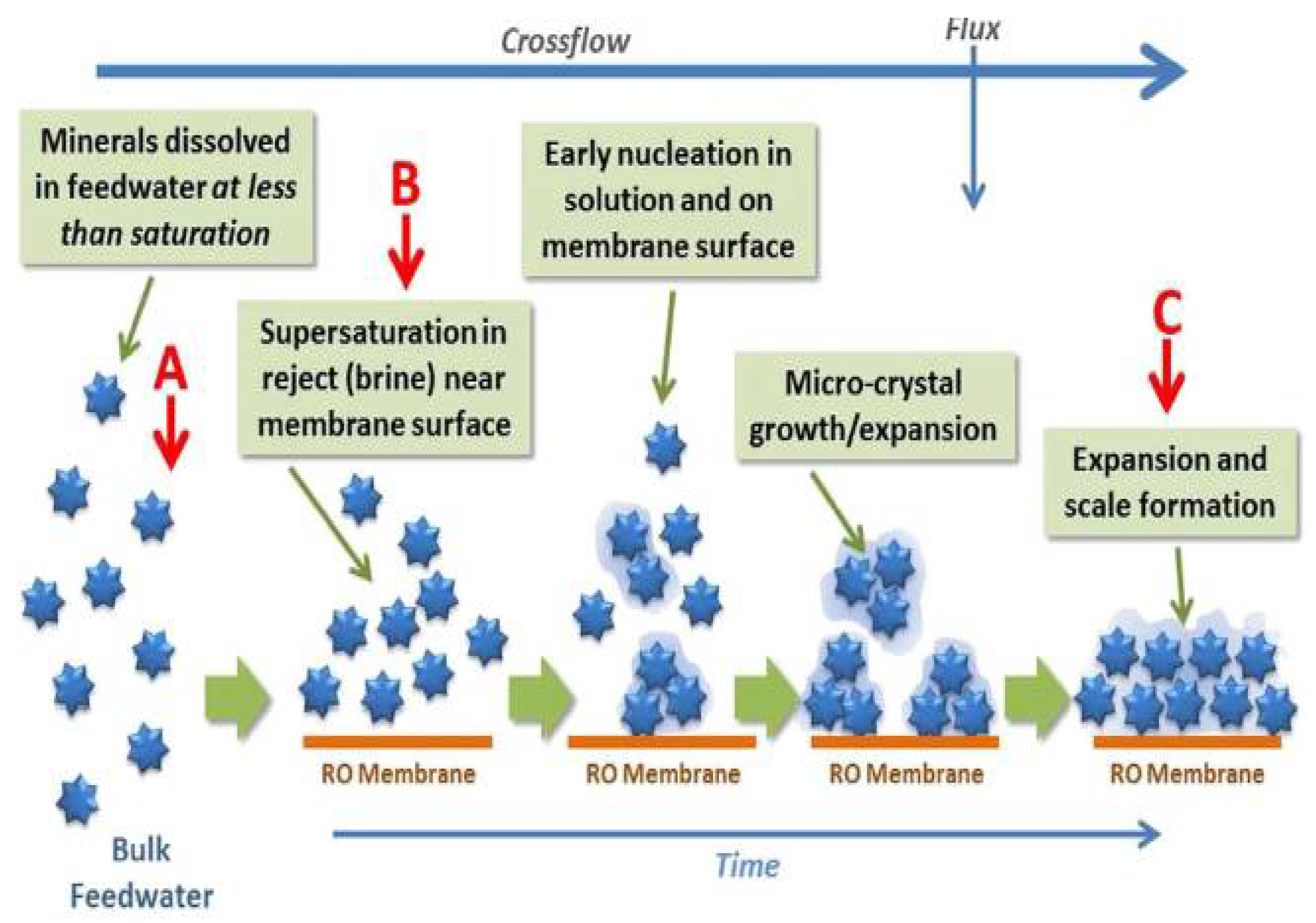
Figure 4.
SEM-EDX and XPS images of the outer surface of the layer of fouled membrane, using the original RO retentate with pH 7.2; RO retentate at pH 5.5; pretreated RO with 1.1 mM EDTA as the feed [63].
Figure 4.
SEM-EDX and XPS images of the outer surface of the layer of fouled membrane, using the original RO retentate with pH 7.2; RO retentate at pH 5.5; pretreated RO with 1.1 mM EDTA as the feed [63].

Figure 5.
The morphology of the membrane surface after filtration and permeate flushing [64].
Figure 5.
The morphology of the membrane surface after filtration and permeate flushing [64].

Figure 6.
3D rendering of OCT image and biomass (dark color) to show the development of a biofilm on a UF membrane (poly acrylonitrile (PAN)), 150 k Da) with 31 µm feed spacer over time. The feed is tap water containing nutrient broth that is enriched to enhance biofilm formation. The MFS operates at 1 bar with a lateral flow rate of 0.16 m/s, in the direction from bottom to top, as indicated by the arrow on the panel on day 1 [66].

Figure 7.
Schematic diagram of the chlorine erosion of PA film and the performance degradation caused by attack [68].
Figure 7.
Schematic diagram of the chlorine erosion of PA film and the performance degradation caused by attack [68].
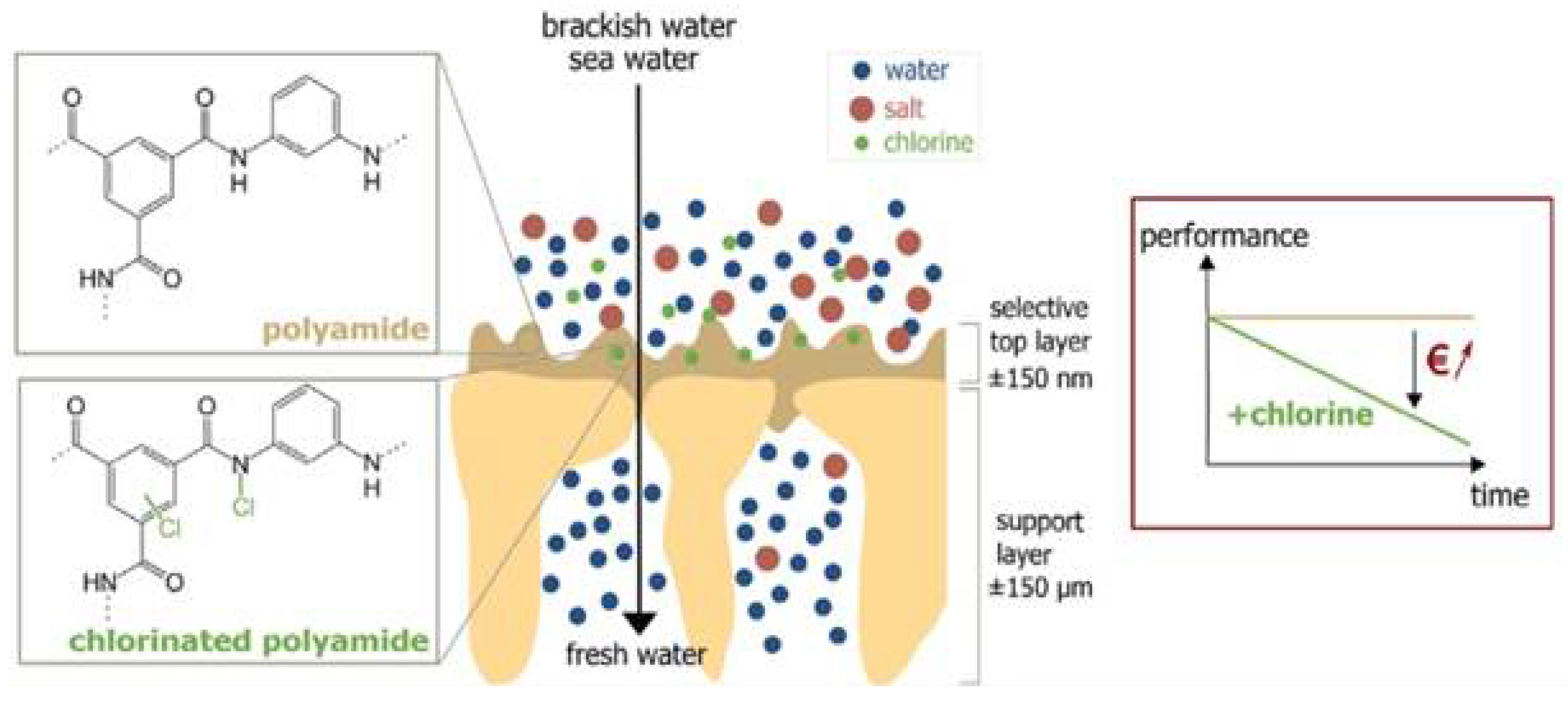
Figure 8.
Electron micrograph of the original nanofilter (a,b); the water from the Foss reservoir from the MF only pretreatment (c,d) is contaminated; the water from the Foss reservoir from the EC-MF pretreatment (e,f) and the model solution (g,h) are contaminated. The 1000× magnified image and the scale bar in the top row represent 100 μm. The bottom row and the 4 μm scale bar show images at a higher magnification (18,000×).
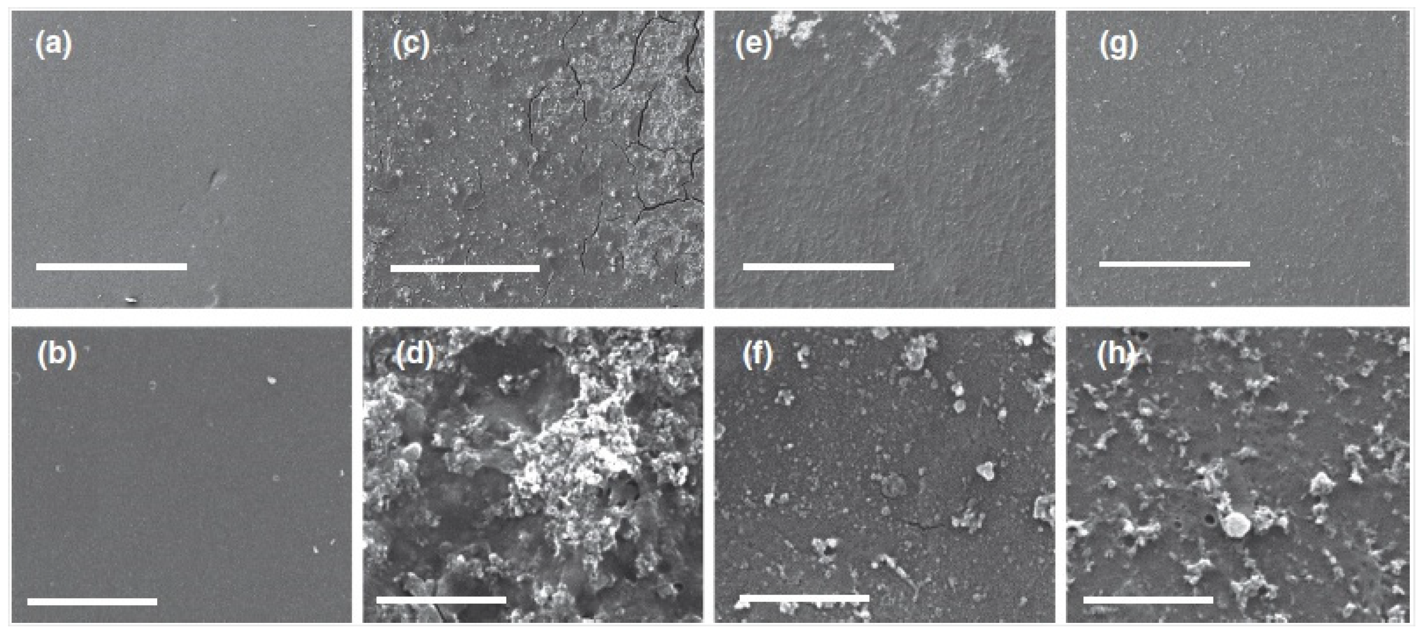
Figure 9.
Schematic diagram of the preparation process and mechanism for the composite membrane [74].
Figure 9.
Schematic diagram of the preparation process and mechanism for the composite membrane [74].
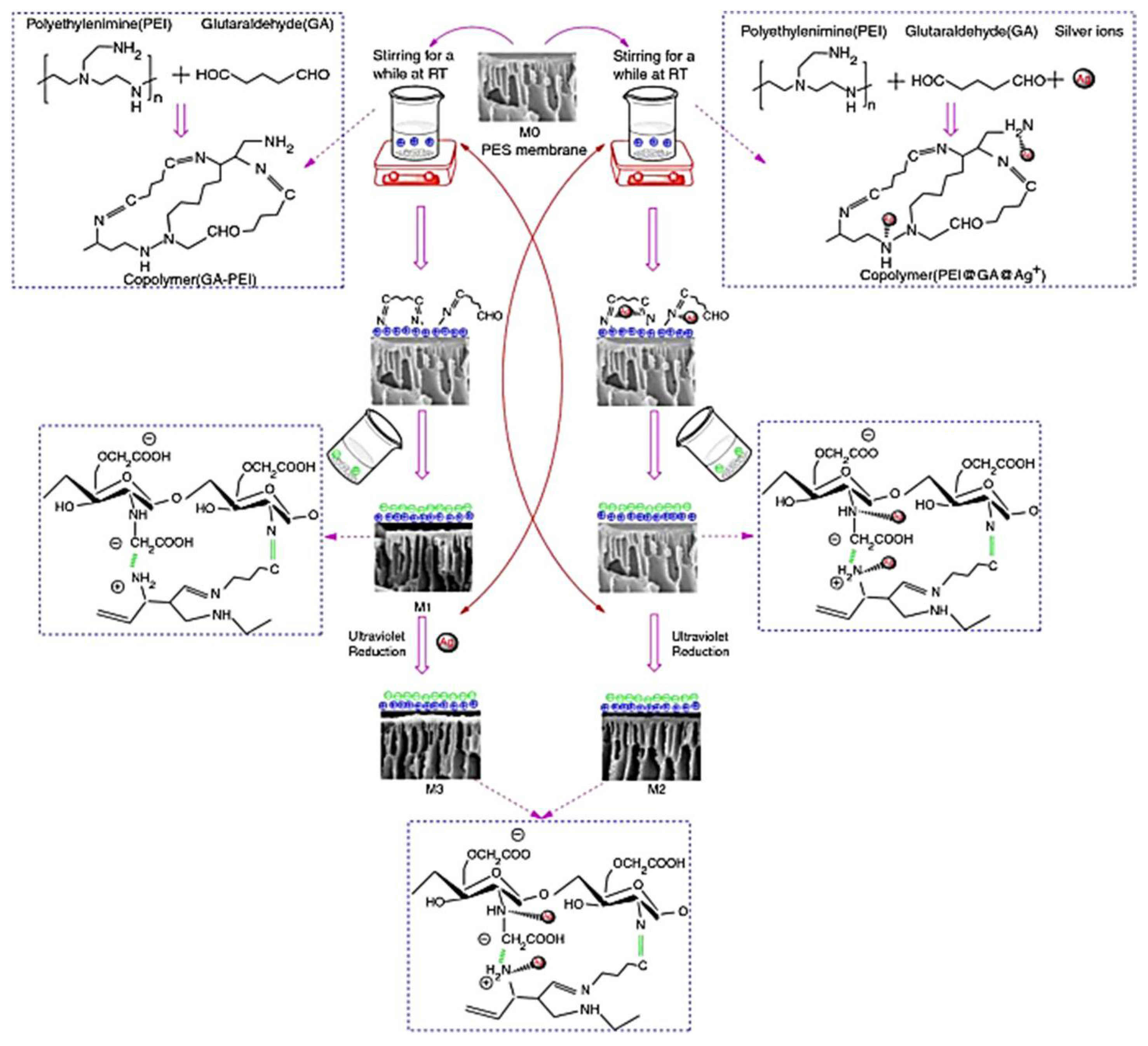
Figure 10.
Schematic depicting how DMs reduce fouling, showing DM deposition, DM saturation by foulants, and ultimately DM removal [81].
Figure 10.
Schematic depicting how DMs reduce fouling, showing DM deposition, DM saturation by foulants, and ultimately DM removal [81].

Figure 11.
Microscopic image of the PES (100 kDa) membrane surface after being sonicated at 47 kHz for 2 h (a) with an 80,000 magnification; (b) a heavily damaged area with a 550 magnification [88].
Figure 11.
Microscopic image of the PES (100 kDa) membrane surface after being sonicated at 47 kHz for 2 h (a) with an 80,000 magnification; (b) a heavily damaged area with a 550 magnification [88].

Figure 12.
Depicts the effect of backpulsing and backwashing on membrane permeability decline: (1) filtration without backwashing or backpulsing, (2) filtration with backwashing, and (3) filtration with backpulsing. Both backpulsing and backwashing are assumed to be capable of completely removing hydraulically reversible fouling and to operate under reasonable conditions [97].
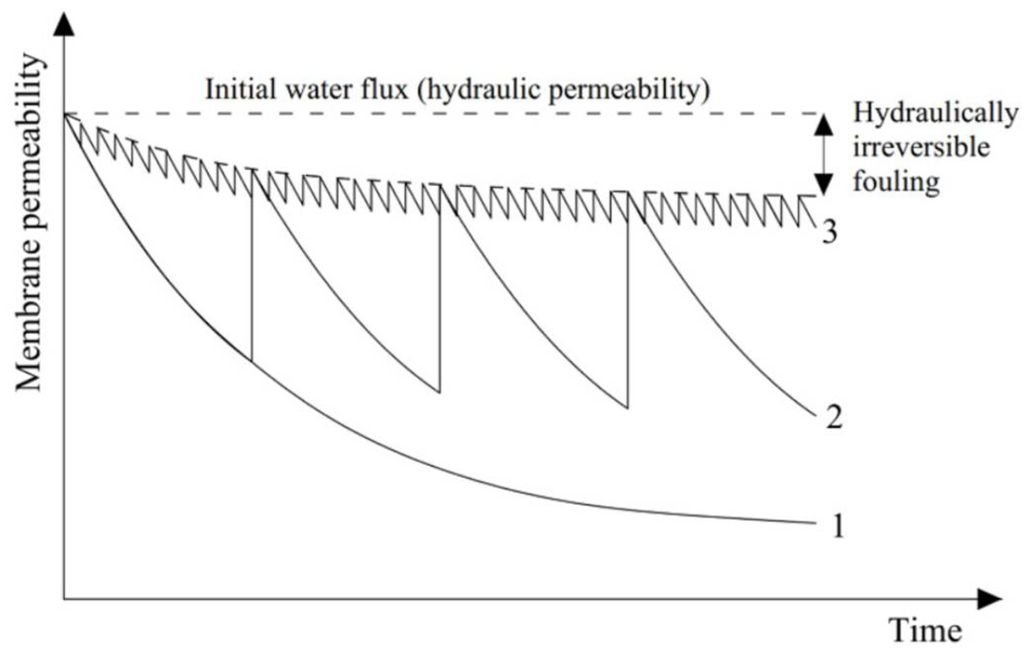
Figure 13.
Depicts an overview of the membrane prior to and after backpulsing in MF and UF processes, where CB, CS, and CP are the concentrations of solutes in the bulk, near the membrane surface, and permeate, respectively [97].
Figure 13.
Depicts an overview of the membrane prior to and after backpulsing in MF and UF processes, where CB, CS, and CP are the concentrations of solutes in the bulk, near the membrane surface, and permeate, respectively [97].

Figure 14.
Ultrasonic cleaning device setup for a dead-end MF: (1) computer, (2) permeation tank, (3) electronic scale, (4) electronic controller, (5) vacuum pump, (6) ultrasonic probe, (7) support membrane, (8) power box, and (9) ultrasonic controller [105].
Figure 14.
Ultrasonic cleaning device setup for a dead-end MF: (1) computer, (2) permeation tank, (3) electronic scale, (4) electronic controller, (5) vacuum pump, (6) ultrasonic probe, (7) support membrane, (8) power box, and (9) ultrasonic controller [105].
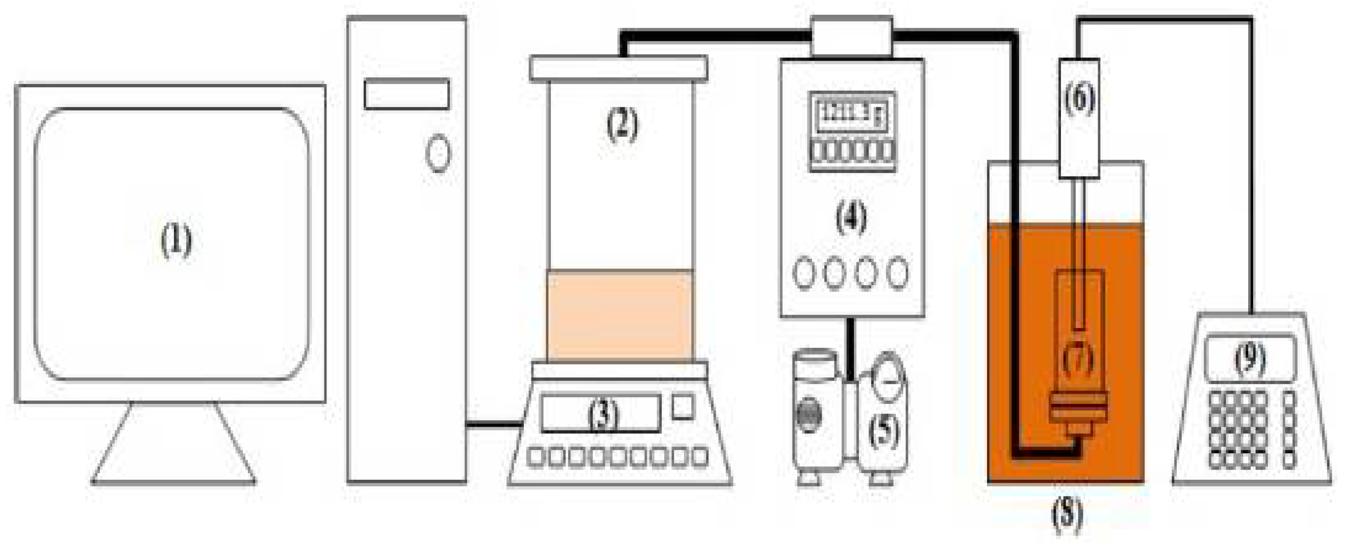
Figure 15.
(a–c) Cross flow membrane module schematic for membrane operation with in-situ ultrasonic generation: (1) symmetric piezoelectric membrane, (2) permeate side mesh electrode, (3) distant rod electrode, and (4) asymmetric structure with conductive membrane layer and piezoelectric support; (d) Process of making a composite membrane [106].
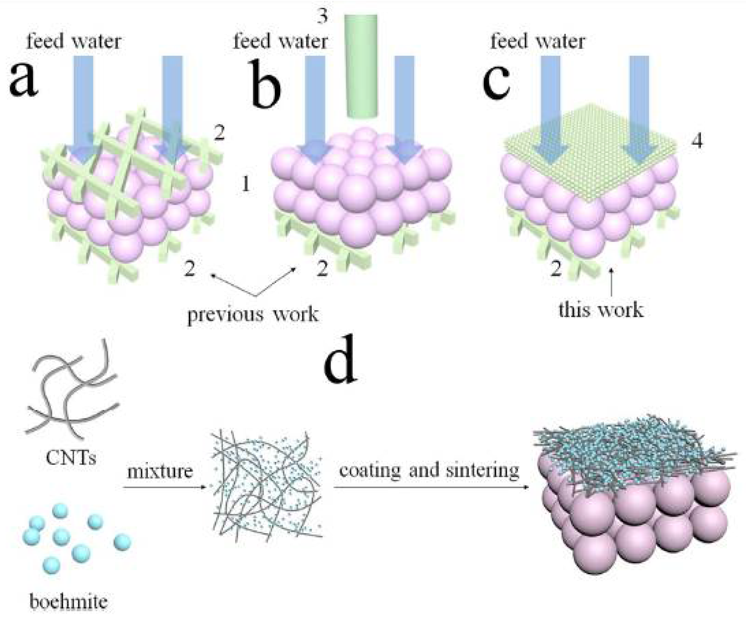
Figure 16.
SEM images of the cake layer in the membrane surface created by: (a) no pretreatment; (b) PAC coagulation system; (c) PAC-PolyDMDAAC coagulation system; (d) PAC + PolyDMDAAC dual coagulation; (e) a schematic of the likely process of membrane fouling by different coagulation systems [108].
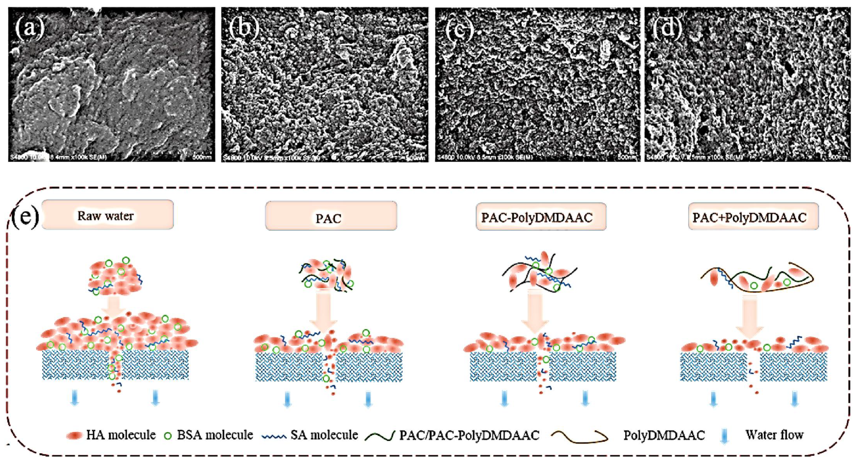
Figure 17.
Schematic explanation of the suggested processes for membrane fouling development in the presence of various cations (Ca2+ or Na+) in the EFMF system at 1.5 V (a) and 3 V (b) [109].
Figure 17.
Schematic explanation of the suggested processes for membrane fouling development in the presence of various cations (Ca2+ or Na+) in the EFMF system at 1.5 V (a) and 3 V (b) [109].
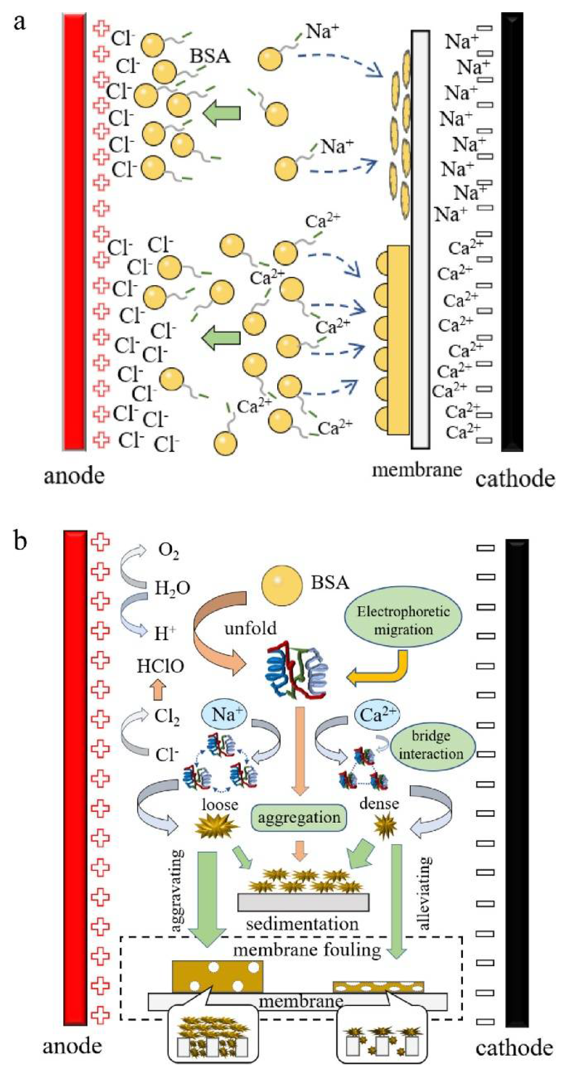
Figure 18.
Concept of membrane surface construction to mitigate oily wastewater problem, using SiO2 as the support layer and GO as the isolation layer [111].
Figure 18.
Concept of membrane surface construction to mitigate oily wastewater problem, using SiO2 as the support layer and GO as the isolation layer [111].
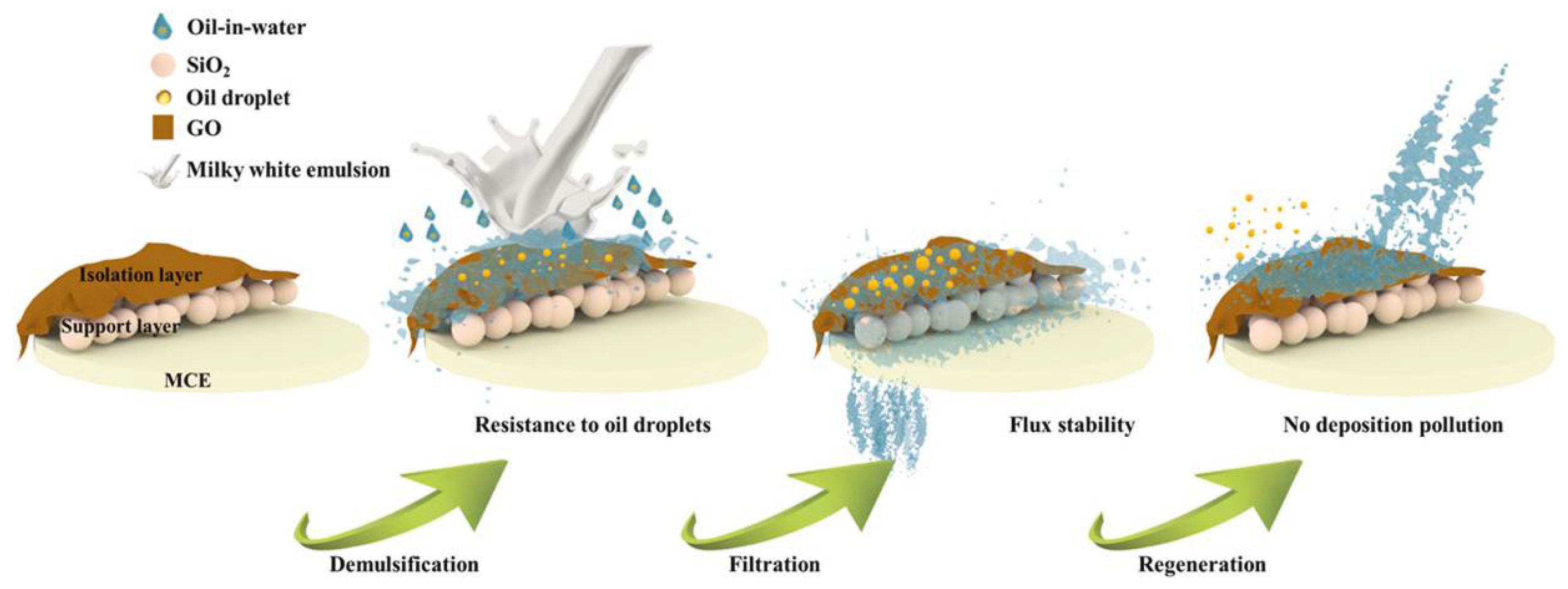
Figure 19.
Shows the applications and advantages of ceramic membranes and ceramic nanocomposite membranes in hybrid water treatment systems over their polymeric counterparts [112].
Figure 19.
Shows the applications and advantages of ceramic membranes and ceramic nanocomposite membranes in hybrid water treatment systems over their polymeric counterparts [112].

Figure 20.
Benefits of dual-objective optimization system accurate forecasts of changing fluctuations in hourly influent [118].
Figure 20.
Benefits of dual-objective optimization system accurate forecasts of changing fluctuations in hourly influent [118].
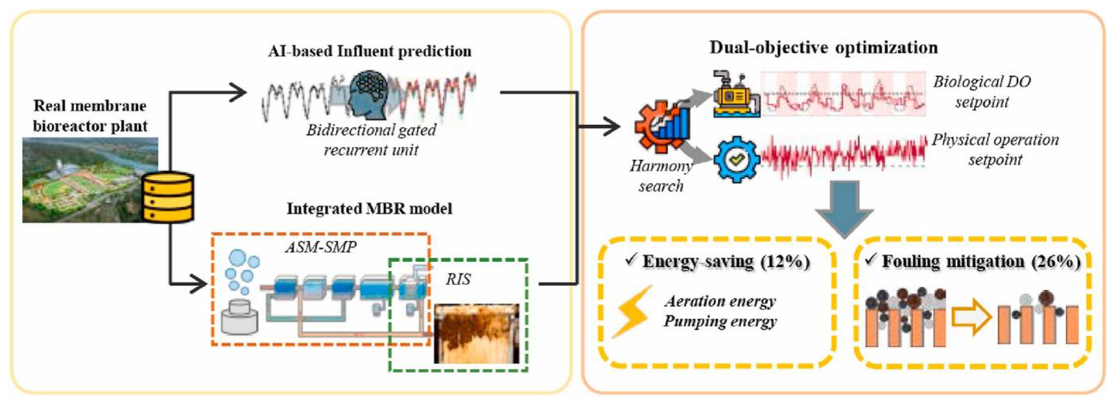
Figure 21.
Established combined system of anaerobic-anoxic-oxic membrane bioreactor (A2O-MBR) and worm reactor (WR) for fouling control [119].
Figure 21.
Established combined system of anaerobic-anoxic-oxic membrane bioreactor (A2O-MBR) and worm reactor (WR) for fouling control [119].
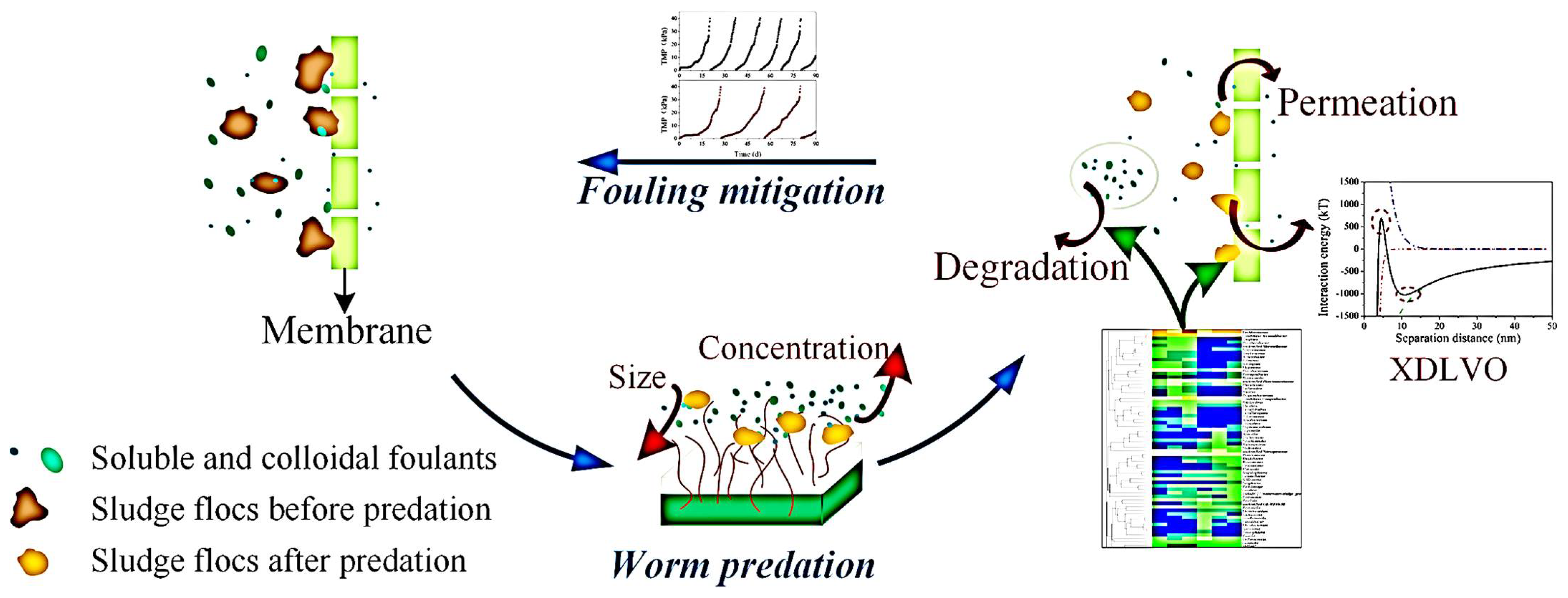
Figure 22.
Three anaerobic baffled biofilm-membrane bioreactor (AnBB-MBR). (a) R1: no media (anaerobic baffled MBR); (b) R2:FF (fixed film AnBB-MBR); (c) R3:FF + MVB (fixed film and moving bed AnBB-MBR) [121].
Figure 22.
Three anaerobic baffled biofilm-membrane bioreactor (AnBB-MBR). (a) R1: no media (anaerobic baffled MBR); (b) R2:FF (fixed film AnBB-MBR); (c) R3:FF + MVB (fixed film and moving bed AnBB-MBR) [121].

Figure 23.
The study and applications of polymer-ZnO membranes [125].
Figure 23.
The study and applications of polymer-ZnO membranes [125].
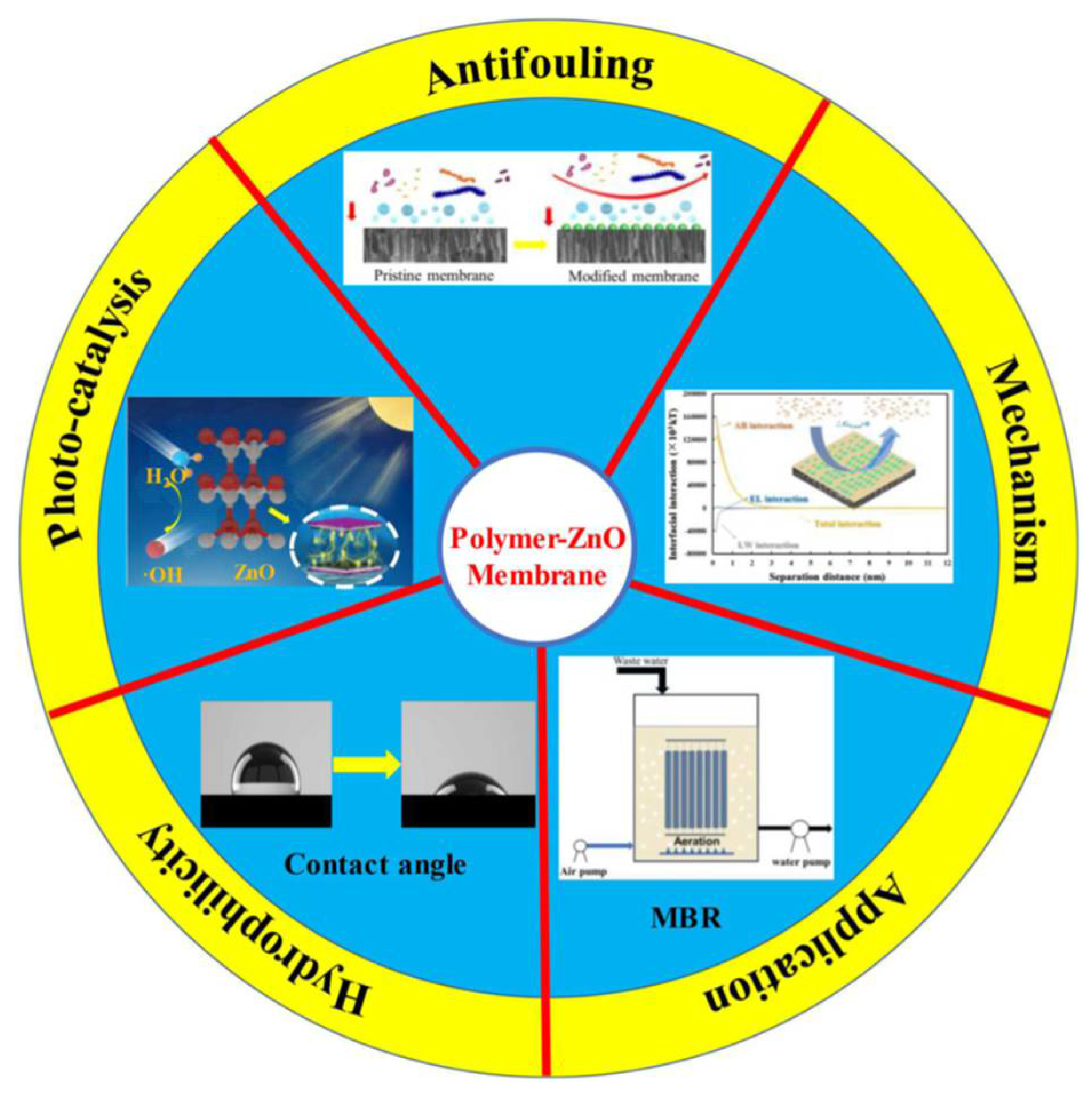
Figure 24.
Types of fouling in MD [132].
Figure 24.
Types of fouling in MD [132].

Figure 25.
Different fouling mitigation methods [132].
Figure 25.
Different fouling mitigation methods [132].
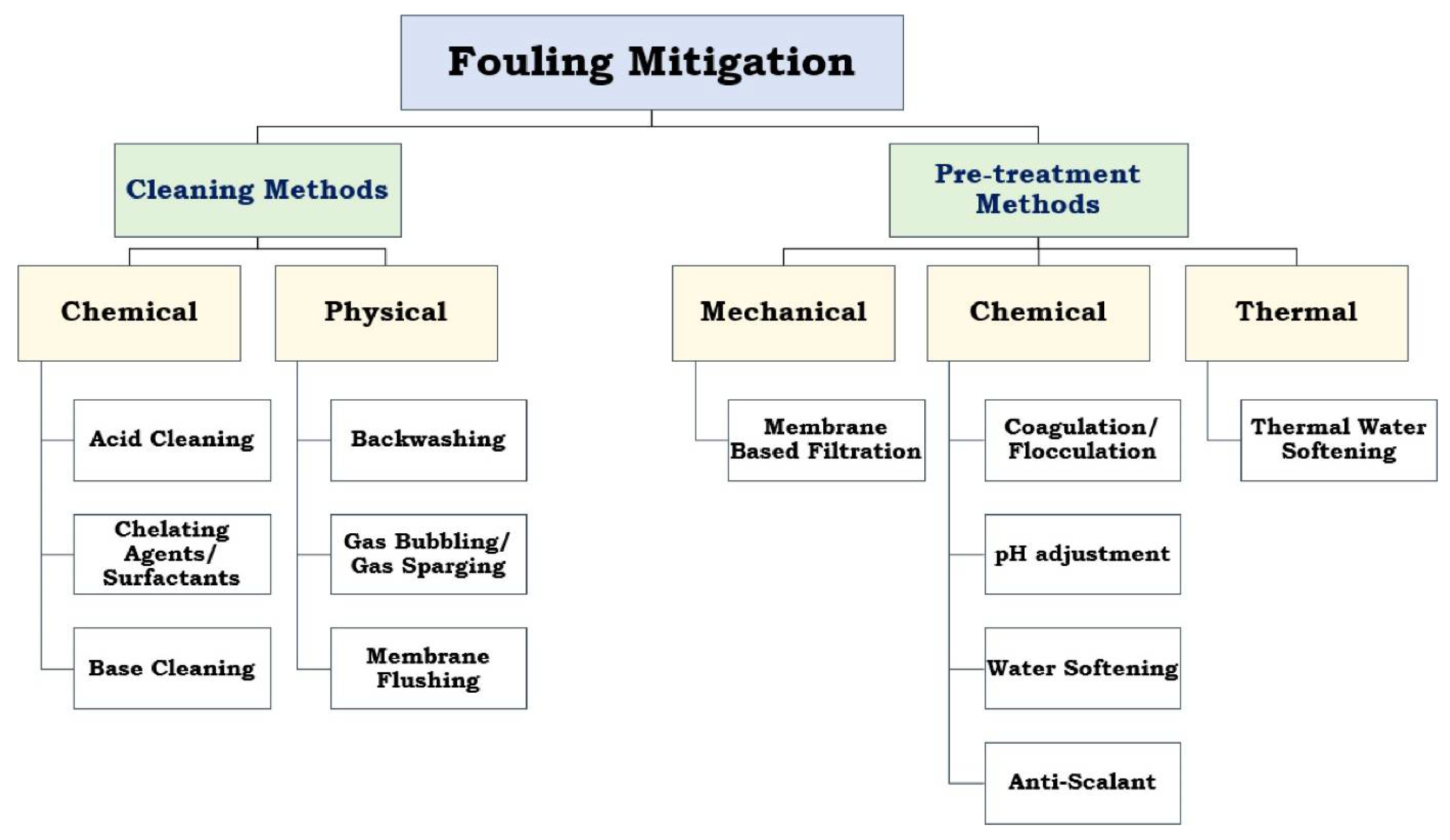
Figure 26.
Different pre-treatment methods for various types of fouling in MD [132].
Figure 26.
Different pre-treatment methods for various types of fouling in MD [132].

Figure 27.
The morphological image of the PTFE membrane after the HA solution concentration experiment: (a) without ultrasonic irradiation; (b) with ultrasonic irradiation [139].
Figure 27.
The morphological image of the PTFE membrane after the HA solution concentration experiment: (a) without ultrasonic irradiation; (b) with ultrasonic irradiation [139].
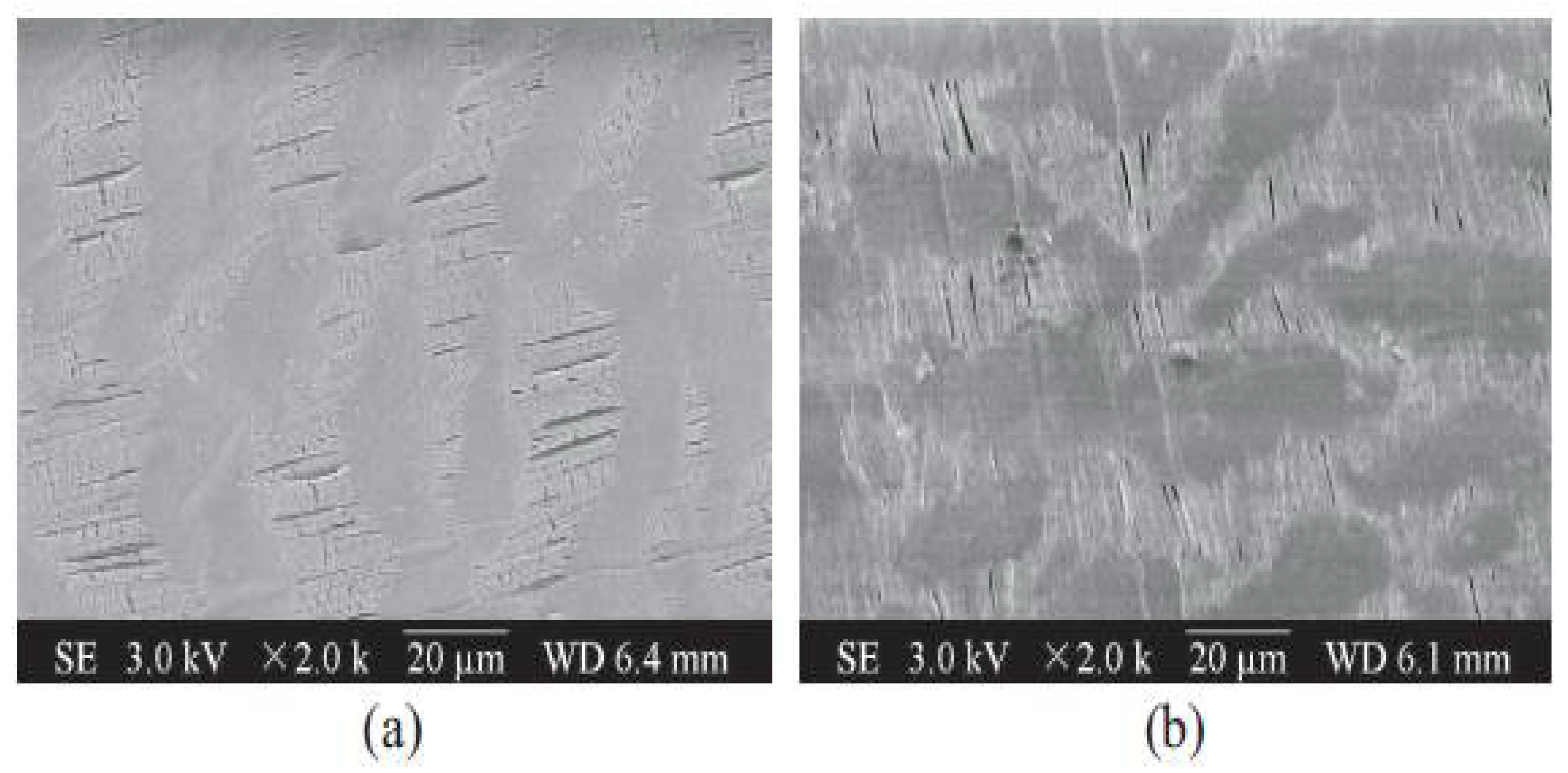
Figure 28.
Morphology images of PTFE membrane after a HA solution concentration experiment under ultrasonic irradiation: (a) 2 Mm CaCl2; (b) 10 Mm CaCl2; (c) 20 Mm CaCl2 [139].
Figure 28.
Morphology images of PTFE membrane after a HA solution concentration experiment under ultrasonic irradiation: (a) 2 Mm CaCl2; (b) 10 Mm CaCl2; (c) 20 Mm CaCl2 [139].
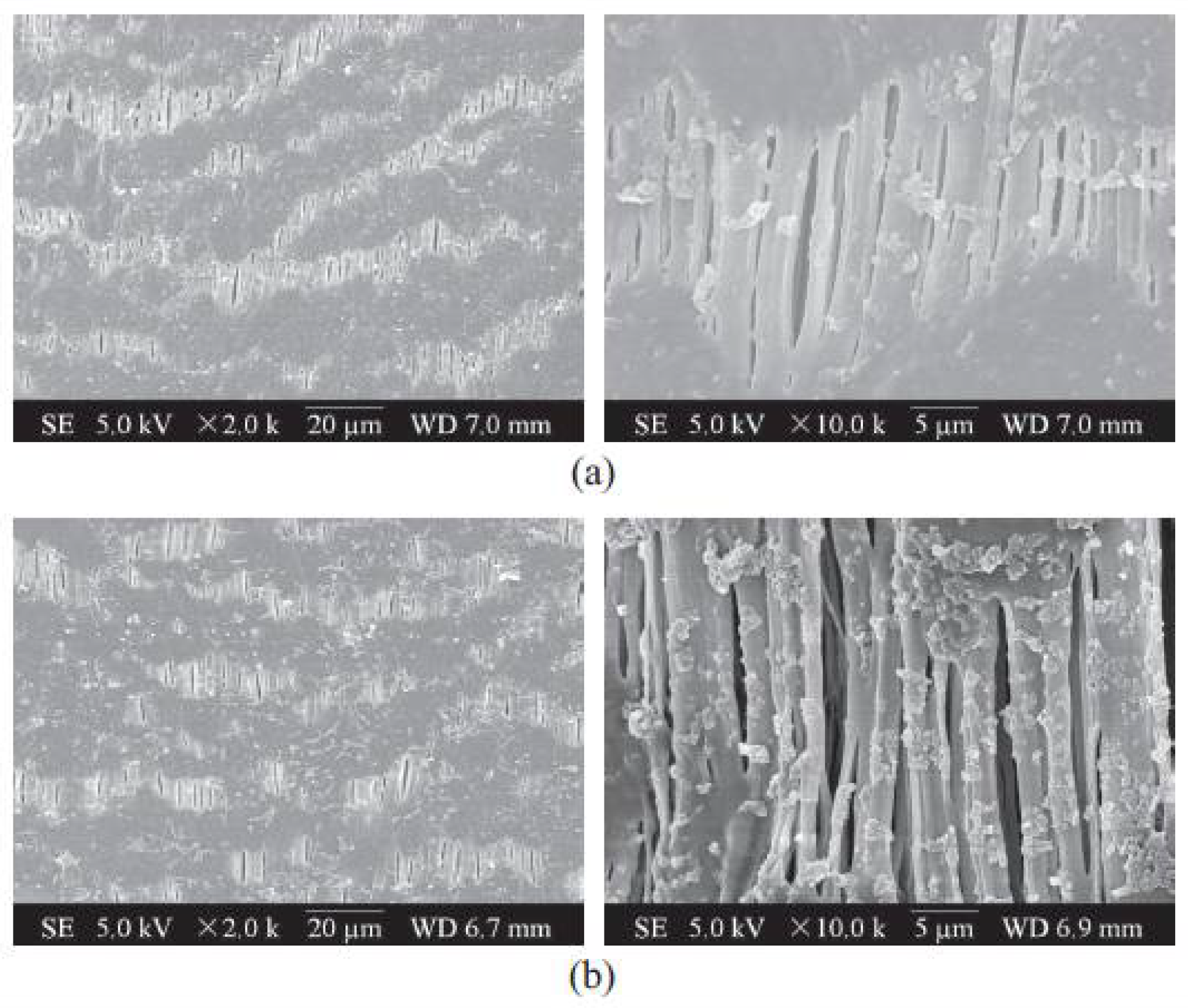

Figure 29.
Morphological images of PTFE membrane after silica solution concentration: (a) 2000×; (b) 5000× [140].
Figure 29.
Morphological images of PTFE membrane after silica solution concentration: (a) 2000×; (b) 5000× [140].
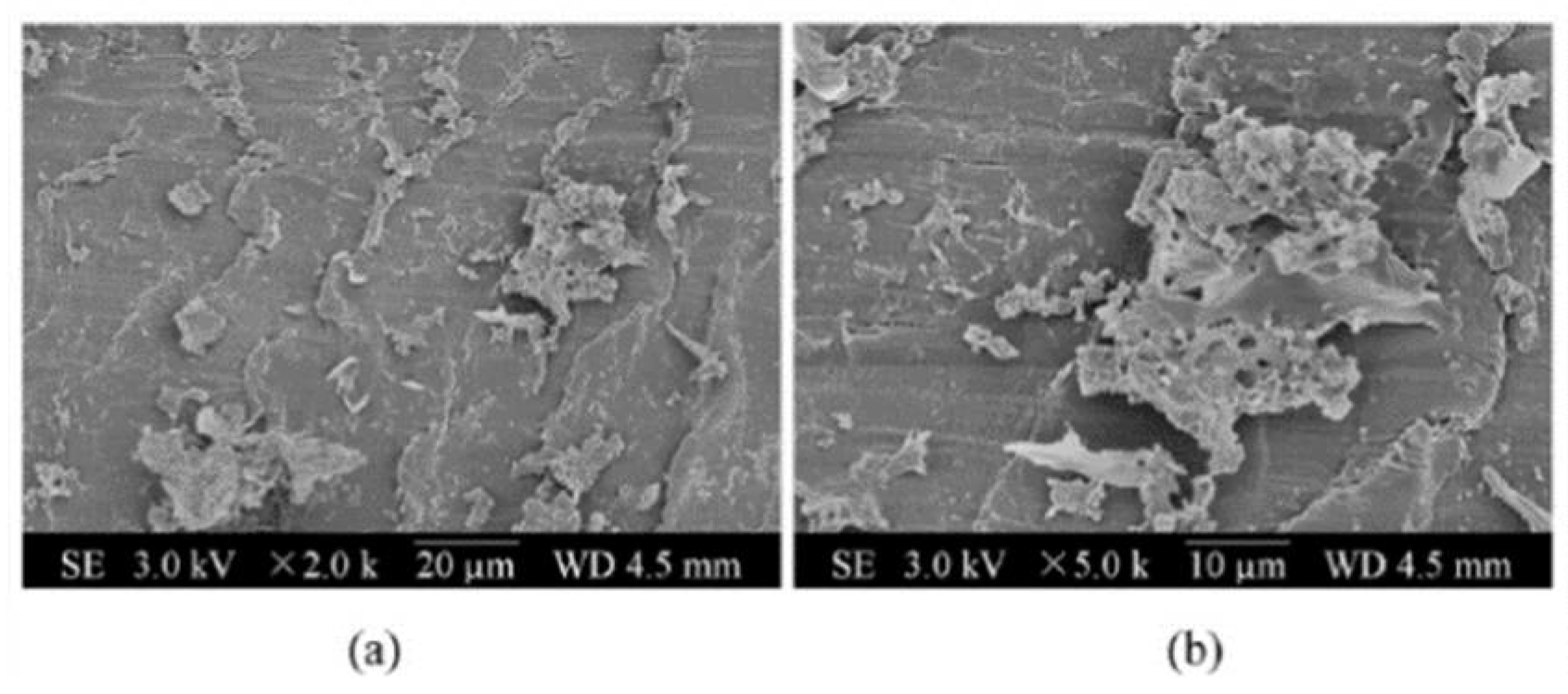
Figure 30.
Schematic diagram of the effect of ultrasonic radiation on reducing the formation of silica scale [140].
Figure 30.
Schematic diagram of the effect of ultrasonic radiation on reducing the formation of silica scale [140].
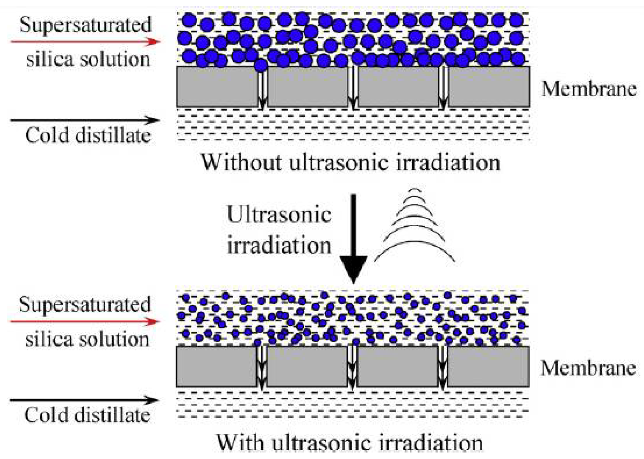
Figure 31.
Morphological images of the PTFE membrane after being irradiated with an ultrasonically concentrated silica solution: (a) 1000×; (b) 2000× [140].
Figure 31.
Morphological images of the PTFE membrane after being irradiated with an ultrasonically concentrated silica solution: (a) 1000×; (b) 2000× [140].

Figure 32.
Model of positively charged colloidal particle [149].
Figure 32.
Model of positively charged colloidal particle [149].
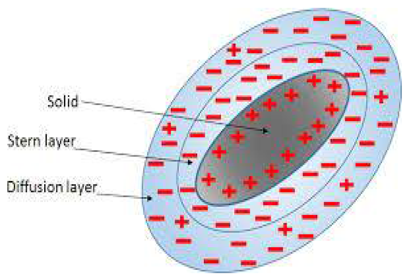
Figure 33.
Examples of organic fouling (adapted with permissions). (A) chitosan fouling [150]; (B) anthocyanin fouling [151]; (C) protein fouling [152]; (D) polyacrylamide fouling [153].
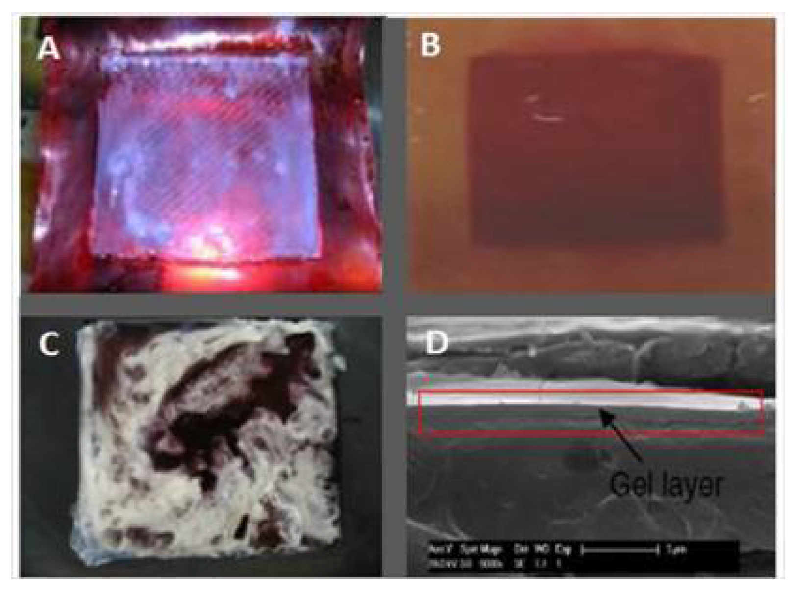
Figure 34.
Depicts the lifetime of a biofilm. The stages of biofilm formation and dispersion are depicted from right to left. The lower panel contains photomicrographs of bacteria at each of the five phases depicted in the above schematic [154].
Figure 34.
Depicts the lifetime of a biofilm. The stages of biofilm formation and dispersion are depicted from right to left. The lower panel contains photomicrographs of bacteria at each of the five phases depicted in the above schematic [154].

Figure 35.
Polarity change in ED processes.
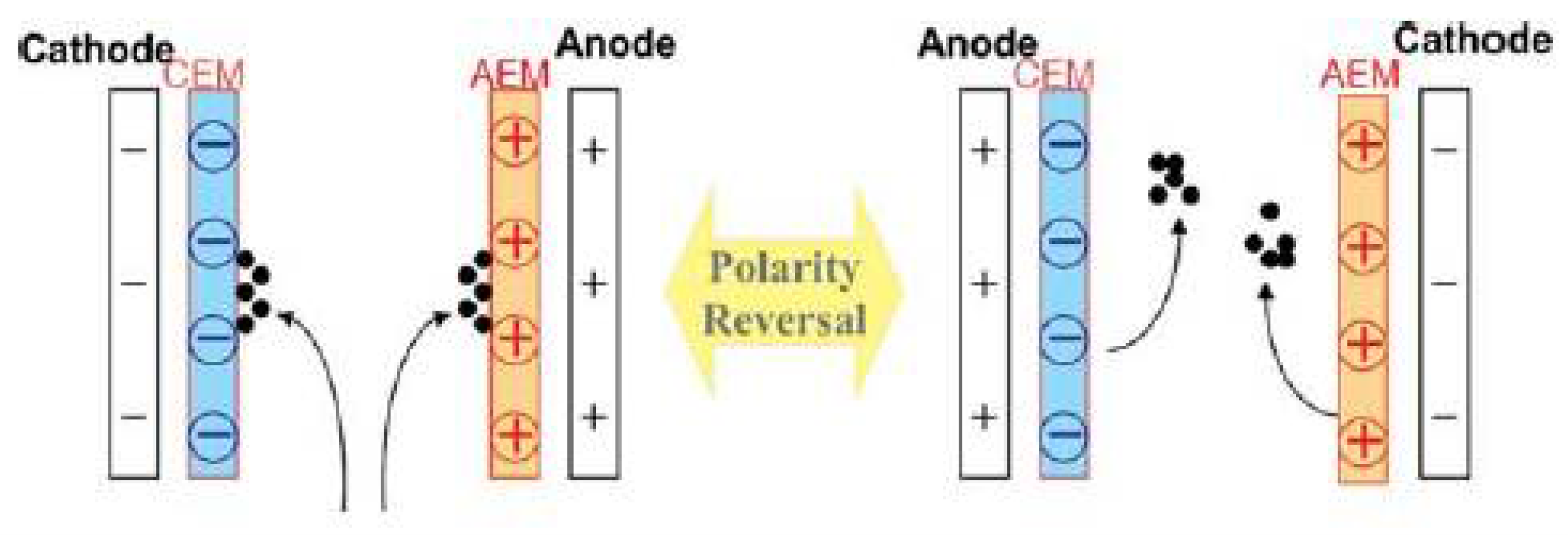
Figure 36.
Mitigation of APAM fouling in ED [164].
Figure 36.
Mitigation of APAM fouling in ED [164].

Figure 37.
Illustration of electro-assisted membrane coupling technology [166].
Figure 37.
Illustration of electro-assisted membrane coupling technology [166].
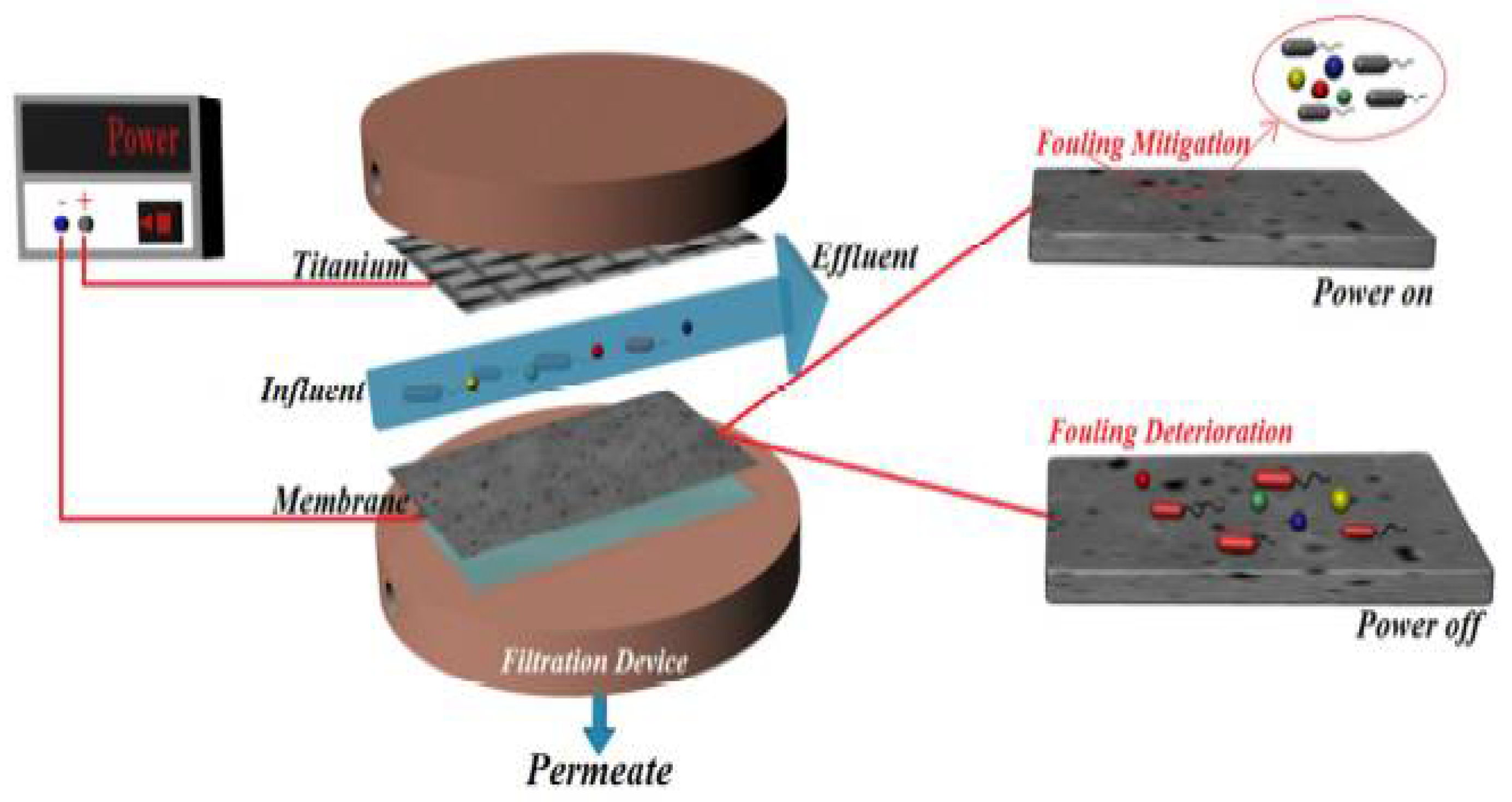

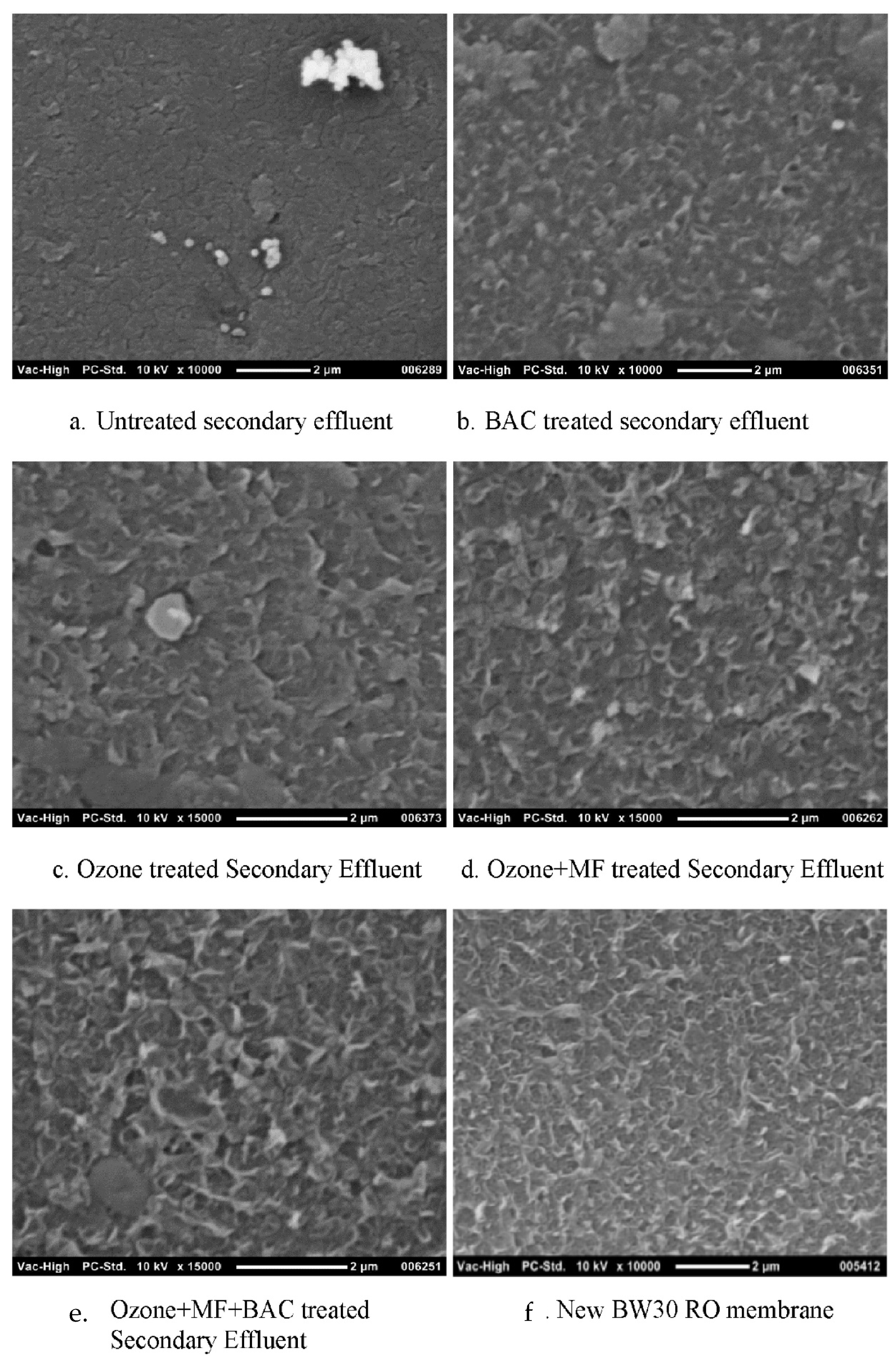
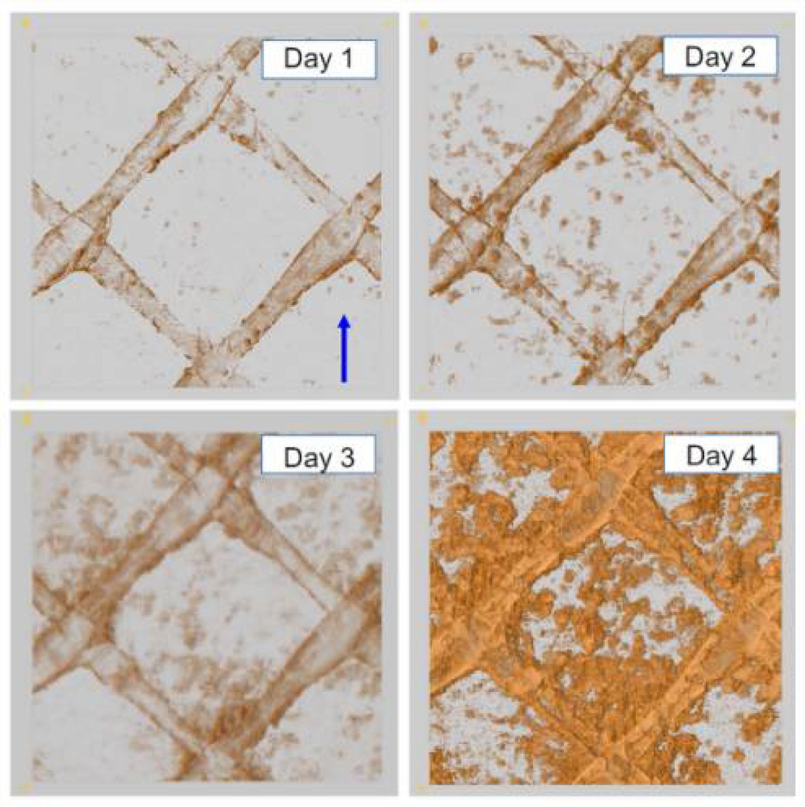
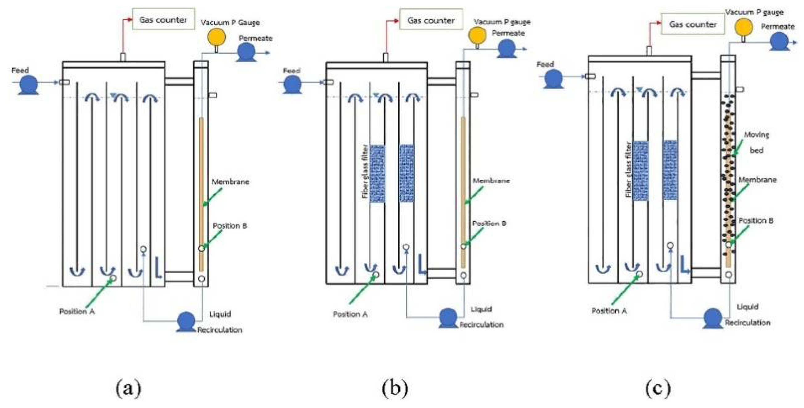
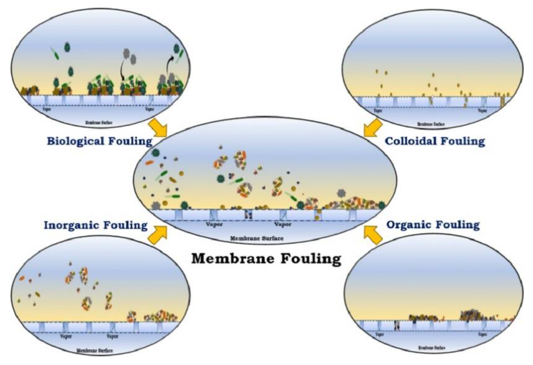
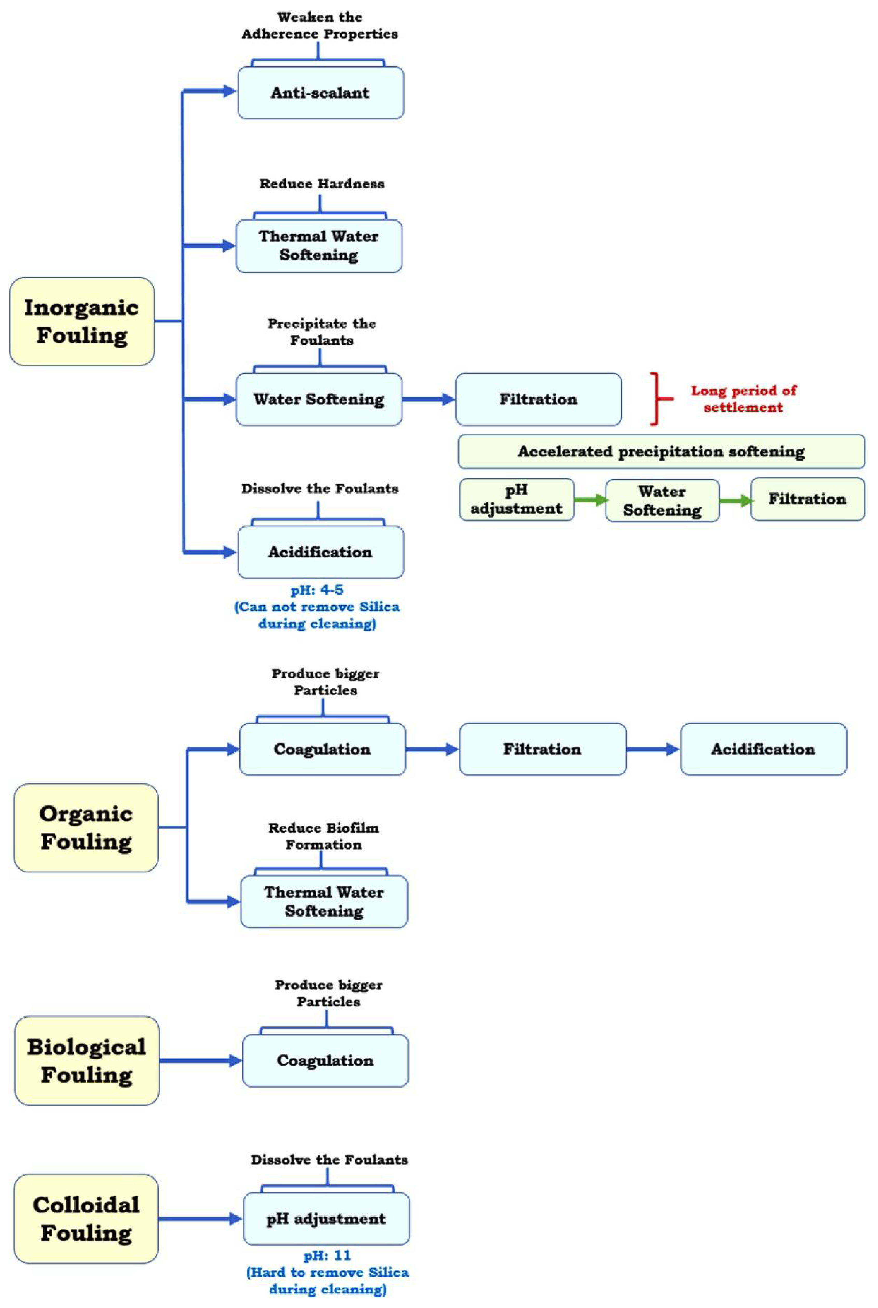
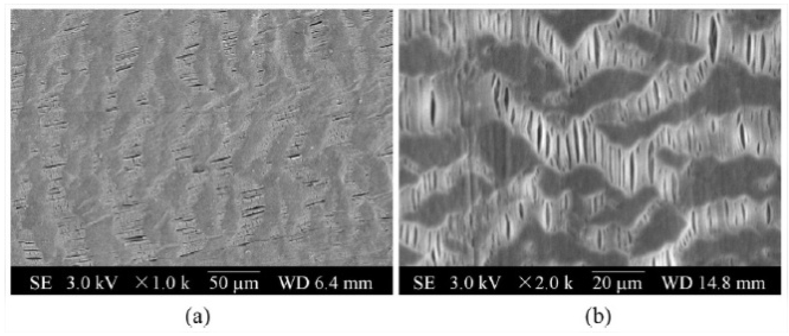
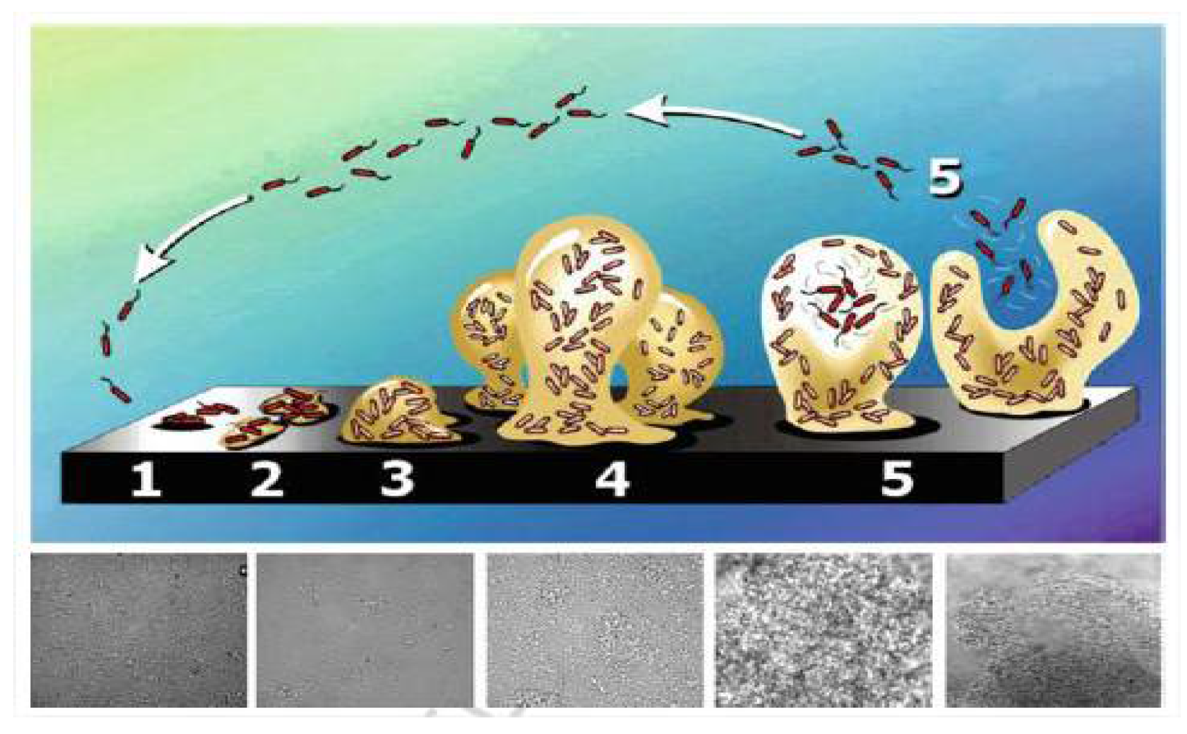
Table 1.
Desired values for the properties of the membranes used in the MD process. Adapted from [129,130,131].
| Property | Affects | Typical Values (Commercial Membranes) | Recommendation |
|---|---|---|---|
| Contact angle (θ) | Wetting resistance | 80°–160° | >90° as high as possible |
| LEP (bar) | Wetting resistance | 0.5–4.6 | >2.5 |
| Thickness (δ) (μm) | Flux, energy efficiency, strength | 20–400 | Low salinity: 30–60 High salinity: 2–700 |
| Porosity (ϵ) | Flux, energy efficiency, strength | 39–90% | >80% |
| Thermal conductivity (km) (W/m k) | Flux, energy efficiency | 0.031–0.057 | As low as possible |
| Tensile strength (MPa) | Strength | 3.4–57.9 | As high as possible |
Publisher’s Note: MDPI stays neutral with regard to jurisdictional claims in published maps and institutional affiliations. |
© 2021 by the authors. Licensee MDPI, Basel, Switzerland. This article is an open access article distributed under the terms and conditions of the Creative Commons Attribution (CC BY) license (https://creativecommons.org/licenses/by/4.0/).
Share and Cite
MDPI and ACS Style
El Batouti, M.; Alharby, N.F.; Elewa, M.M. Review of New Approaches for Fouling Mitigation in Membrane Separation Processes in Water Treatment Applications. Separations 2022, 9, 1. https://doi.org/10.3390/separations9010001
AMA Style
El Batouti M, Alharby NF, Elewa MM. Review of New Approaches for Fouling Mitigation in Membrane Separation Processes in Water Treatment Applications. Separations. 2022; 9(1):1. https://doi.org/10.3390/separations9010001
Chicago/Turabian StyleEl Batouti, Mervette, Nouf F. Alharby, and Mahmoud M. Elewa. 2022. "Review of New Approaches for Fouling Mitigation in Membrane Separation Processes in Water Treatment Applications" Separations 9, no. 1: 1. https://doi.org/10.3390/separations9010001
Note that from the first issue of 2016, this journal uses article numbers instead of page numbers. See further details here.