
The Effect of Rotation on Gas Storage in Nanoporous Materials
by
 ,
,
Athanasios Ch. Mitropoulos
1,*, 
Ramonna I. Kosheleva
1,2,
Margaritis Kostoglou
2 and
Thodoris D. Karapantsios
2
1
Hephaestus Laboratory, Department of Chemistry, School of Sciences, International Hellenic University, St. Lucas, 654 04 Kavala, Greece
2
Faculty of Chemistry, Division of Chemical Technology, Aristotle University of Thessaloniki, University Box 116, 541 24 Thessaloniki, Greece
*
Author to whom correspondence should be addressed.
Separations 2024, 11(3), 72; https://doi.org/10.3390/separations11030072
Submission received: 31 January 2024
/
Revised: 21 February 2024
/
Accepted: 22 February 2024
/
Published: 24 February 2024
(This article belongs to the Topic Porous Materials for Energy and Environment Applications)
Abstract
:Nanoporous materials offer a promising solution for gas storage applications in various scientific and engineering domains. However, several crucial challenges need to be addressed, including adsorptive capacity, rapid loading, and controlled gas delivery. A potential approach to tackle these issues is through rotation-based methods. In this study, we investigate the impact of rotation on CO2 adsorption using activated carbon, both at the early and late stages of the adsorption process. Towards this direction, three sets of experiments were conducted: (i) adsorption isotherm with rotation at each gas loading, (ii) adsorption kinetics with multiple rotations performed in sequence 15 min after CO2 introduction, and (iii) adsorption kinetics with a single rotation after 40 h of adsorption and repetition after another 20 h. For the first two cases, the comparison was performed by respective measurements without rotation, while for the last case, results were compared to a theoretical pseudo-first-order kinetic curve. Our findings demonstrate that rotation enhances the adsorptive capacity by an impressive 54%, accelerates kinetics by a factor of 3.25, and enables controllable gas delivery by adjusting the angular velocity. These results highlight rotation as a promising technique to optimize gas storage in nanoporous materials, facilitating advancements in numerous scientific and engineering applications.
1. Introduction
Gas storage plays a pivotal role in ensuring energy security, grid stability, and the transition to a more sustainable energy future. Challenges that impact gas storage technologies [1,2] include effectiveness, scalability, and overall implementation, especially for mobile devices and vehicles.
The storage of gases in nanoporous materials and their subsequent transport and use is a modern challenge in chemical technology. There are various gases whose storage in porous media is useful and desirable. The storage of gases in porous media is useful because porous materials offer the possibility of storing larger quantities in proportion to the volume available compared to cylinders and tanks. It is also desirable because they require lower pressures and therefore provide higher safety in the workplace.
Historically, gas storage technology in porous media referred to the use of depleted reservoirs for the storage of transported natural gas. It was later realized that other gases also needed storage with functional transport and release capabilities. Today, storage technology is applied (a) for the environmental remediation of greenhouse gases (e.g., CO2, NOx, SOx, etc.) and (b) for the efficient and safer energy recovery of gases such as CH4 and H2 [3,4]. The first case aims at the permanent removal of gases that, according to the European Union as well as the US Environmental Protection Agency, are considered pollutants, while the second case concerns their temporary storage until they are used [5]. Among these gases, this paper focuses on CO2 as the most typical greenhouse gas [6].
Various methods have been developed for CO2 capture and storage [7,8]. Among them are (a) carbon capture and sequestration (CCS) and (b) carbon capture and storage (CCS). Classical CO2 capture techniques are carried out at the point of production and include (i) pre-combustion or stream purification [3] and (ii) post-combustion CO2 capture [9]. However, due to the severe problem of climate change, direct capture of CO2 from the atmosphere (direct air capture—DAC) is also highly desirable [10]. The above-mentioned techniques make use of either chemical compounds (e.g., ionic liquids) or porous materials (adsorption) [11].
Although adsorption of gases into porous materials is one promising method, optimizations are still needed. The main solids in use are activated carbon and metal–organic frameworks [12,13]. Again, the effort to produce new porous materials goes on very intensively [14,15], but there are still challenges to overcome.
There are three major requirements that a storage system must fulfill [16,17]: (a) sufficient storage capacity, (b) fast loading, and (c) controllable delivery. However, the methods to satisfy these requirements vary widely depending on the gas and the solid to be used. A popular method is the physisorption of the gas on activated carbon (AC) at ambient temperature [18,19]. One reason is that AC is an economical material; another reason is that the sample holder is simply a vessel filled with a closed random pack of AC granules that may easily accept modifications, e.g., for the proper control of input and output of the gas [20,21]. Opposite to the case of H2 storage materials, studies on CO2 adsorbents are scattered, and there is a lack of a systematic categorization based on criteria like adsorption capacity and working conditions. In this framework, a rigorous literature review has been conducted on carbon-based materials for CO2 adsorption; the results are presented in Table 1.
It is well-known that under rotation, a packed bed promotes process intensification [28,29]. A porous packed bed (PPB) is characterized by two porosities: intra- and inter-granular [30,31]. Again, the behavior of the spinning gas is important for a rotating device. Geyko and Fisch [32] have outlined a theoretical study on ideal spinning gas. Liu et al. [33] have extended this study on van der Waals gases, and Zhang et al. [34] have generalized the theory for a non-ideal gas by using the virial equation.
To the best of our knowledge, although there are a number of studies regarding the effect of a rotational field in systems including adsorption such as rotating packed beds (RPBs), they are limited in investigating only phenomena like mass and heat transfer for continuous flow which most of the times refers to a three-phase system. However, such conditions are inadequate for the examination of valuable parameters in regard to the impact of rotation on inherited properties (i.e., adsorption capacity) required for the optimization of a system with no steady-state flow, like gas storage applications based on adsorption. To this end, this study attempts to shed light on the mechanism that is enabled when adsorption occurs under rotation in a closed system.
Kosheleva et al. [35] have conducted an experimental study on the effect of spinning gas on the adsorption process. They have suggested that rotation increases the amount adsorbed. Guo et al. [36] studied the mechanism of gas–solid adsorption under rotation based on the particle diffusion model involved. Their finding suggests that in a rotating PPB, intraparticle diffusion is dominant and is the driving force of the so-called deep adsorption.
For an ideally behaved gas, rotating a disc-shaped container causes the concentration to increase at the perimeter and decrease at the center due to centrifugation. In this study, we have examined the effect of rotation on the adsorption process in the aforementioned frame of gas storage. Experimental measurements on adsorption and adsorption kinetics with and without rotation have been recorded. We have organized this work in three sections regarding the experimental procedure. The first section presents the adsorption isotherm experiment. Two adsorption isotherms were produced and compared, with and without rotation. Next, CO2 kinetics were examined after multiple rotations at an early stage of the adsorption, while a comparison with kinetics for the same period of time but without rotation was conducted as well. Finally, rotation at a late stage was performed after ~40 h, and a second one after a total of ~60 h CO2 adsorption, and the results were fitted to a pseudo-first-order (PFO) kinetic curve in order to showcase the effect of the rotation. The results are analyzed accordingly, and the mechanism constituting each case is discussed.
2. Experimental Details
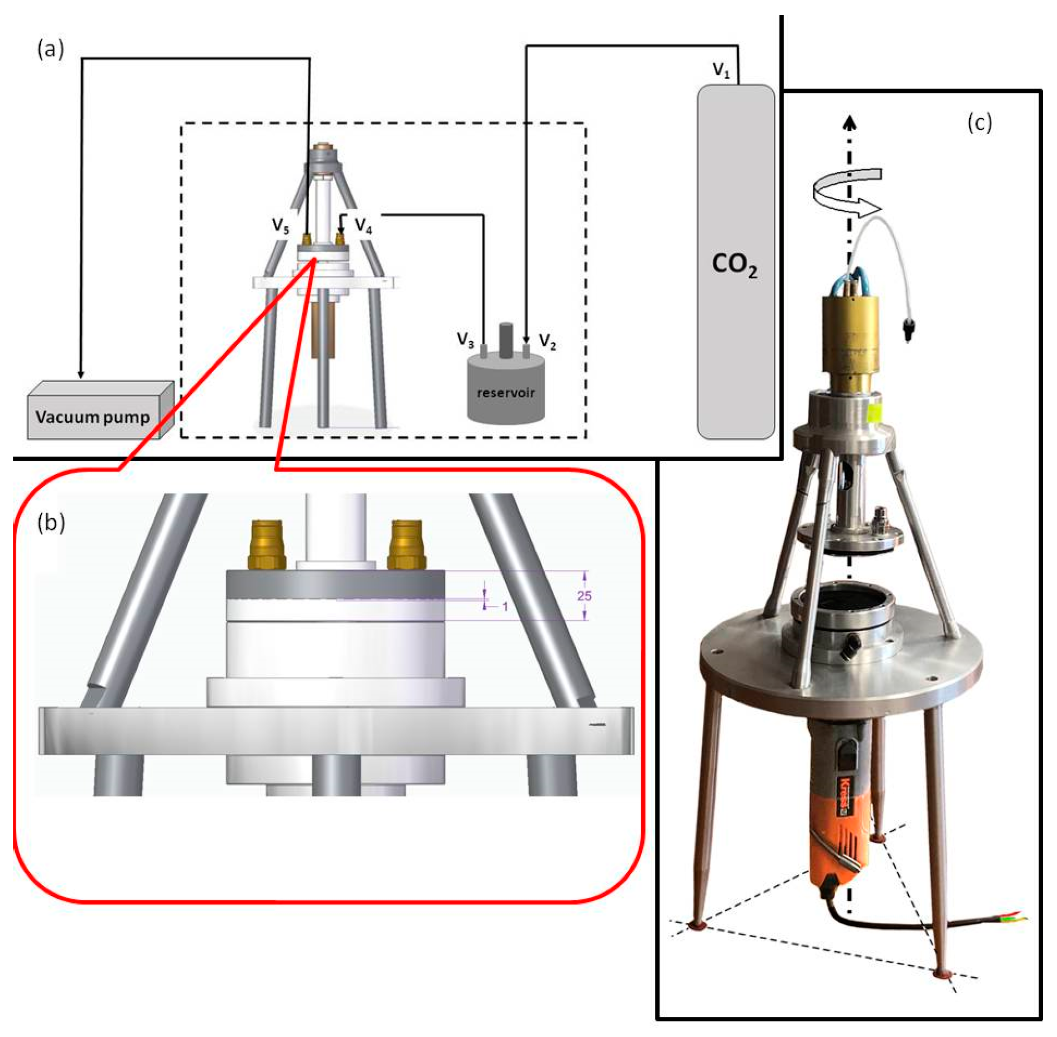
The effect of rotation on the adsorption and adsorption kinetics of CO2 on activated carbon was examined. A specially designed sample cell that allows adsorption in situ with rotation was constructed (Figure 1). The device consisted of a low-vibration rotating motor and a rotating sample chamber of radius rcell = 4.5 cm and height h = 1 mm. All rotations were conducted for 1 min at 5000 rpm. Isothermal temperature was maintained by air-conditioning. During rotation, a negligible temperature increase of about +0.5 °C was observed. To monitor this, a digital thermometer was used to record °C/s. A reservoir tank, connected to the sample cell on one end and to the gas container on the other, was employed as a vessel of known volume that served as a gas dosage regulator.
2.1. Adsorption Isotherms
For conducting the adsorption isotherms experiments, 3.6 g AC was placed into the sample cell. The cell was tightly closed, and the system was set for evacuation overnight. After that, the sample cell was isolated (by closing the valves) from the reservoir tank. A desired amount of CO2 was introduced into the reservoir tank. For the first pressure step, the valve to the sample cell was opened and closed immediately after achieving pressure equilibration between the reservoir tank and the sample cell (<2 s). Finally, the pressure was recorded for 60 min at 1 s intervals. Rotation was enabled at each pressure step after 15 min of CO2 introduction.
2.2. Adsorption Kinetics
For the performance of kinetics, the steps until system evacuation were the same. Next, CO2 was introduced at a desired pressure while recording the pressure drop over time started. Rotation took place according to each experiment; see text under results. More experimental details are given elsewhere [37].
Commercially available activated carbon (AC), with grains of size 100 μm, was used in this study. A N2-adsorption isotherm of AC at 77 K was measured with a Nova 4200e porosimeter (Quantachrome, Boynton Beach, FL, USA). The BET area was estimated to be equal to about 1000 m2/g, and the average pore size, based on the BJH method, was equal to 16 Å. The mass of the AC bed was mAC = 3.6 g with solid and bulk densities of ρs = 2 g/cm3 and ρb = 0.9 g/cm3, respectively. The intra-, inter-, and total porosities ε of the system were then calculated as follows:
where VG = 6.36 cm3 is the geometric volume of the cell, and Vb = mAC/ρb = 4 cm3 is the bulk volume of the solid; εintra = 55%, εinter = 37%, and εtot = 72%.
εintra = (ρs − ρb)/ρs, εinter = (VG − Vb)/VG, and εtot = (εintraVb + εinterVG)/VG,
2.3. Adsorption Isotherms under Rotation
Adsorption isotherms at 20 °C with and without rotation were measured by the aforementioned device. The isotherm measurements were conducted in a sequence of pressure steps, where the sample cell started from vacuum conditions, and gas was introduced in controllable dosages up to 10 bar. The control of the step was provided by the reservoir tank described above. For the former case and at each pressure step, rotation was conducted for 1 min after 15 min of CO2 introduction. When rotation ceased, the system was left for 45 min before receiving the measuring point.
Figure 2 shows the results. Subsequently, the adsorption isotherms were fitted to the Langmuir model:
where qt is the amount adsorbed, qe is the maximum amount adsorbed, and Keq is the Langmuir constant. For the case without rotation, Keq = 0.213 and qe = 0.016 kg/kg, whereas for the case with rotation, K′eq = 0.082 and q′e = 0.035 kg/kg (the prime denotes rotation). Rotation changes the Langmuir constant in a way that Keq > K′eq while qe < q′e. We have verified this trend by repeating the experiment with a single rotation as well as with a different type of AC. Although the decrease in the Langmuir constant indicates weaker adsorption, the increase in qe indicates a higher concentration of gas molecules over the solid surface [38,39]. Rotation increases the strikes of the adsorbed molecules onto the surface and also pushes some of them to previously inaccessible sites following deep adsorption, as described by Guo et al. [40].
Figure 3 shows this mechanism where an element of the solid surface is depicted. The system at a given pressure P has 2 occupied sites and 1 unoccupied site; therefore, kaPS = kdA where S are the unoccupied sites and A are the adsorbed molecules. Rotation makes accessible previously inaccessible sites, leading to 3 adsorbed molecules and 2 unoccupied sites; therefore, at the same given pressure, P, ka′PS′ = kd′A′. Since Keq = ka/kd > k′a/k′d = K′eq, by comparing these two situations, it becomes clear that A/S must be greater than A′/S′ while A < A′ and S < S′. The above inequality is compatible with the case described in Figure 3; for example, the ratio for the no-rotation case is A/S = 2/1, while the ratio for the rotational one is A′/S′ = 3/2.
3. Kinetics
We have conducted two adsorption kinetic experiments with CO2 on AC PPB. In the first experiment, multiple rotations at an early stage of the adsorption process were conducted at 10 °C. In the second one, a single rotation at a late stage of the adsorption process was conducted at 20 °C, followed by another rotation in a similar manner after some time.
Figure 4 shows the results of the first experiment. The reference curve (i.e., without rotation) was fitted to a non-linear pseudo-first-order (PFO) curve by least squares:
where Pth is the theoretical pressure to be compared with the experimental one, Pmax = 9190 mbar is the initial pressure, Peq = 2555 mbar is the equilibrium pressure, k1 = 0.206 is the PFO constant, and t is the time. Multiple rotations have started 20 min after gas entry into the cell and continue for 60 min with 1 min rotation every 15 min, i.e., four rotations in total. Without rotation, the pressure drops to 2270 mbar after 26 h. With multiple rotations, the system reaches the same pressure within 8 h, while after 26 h, the pressure drops to 830 mbar. Rotation makes the process 3.25 times faster with 63% more amount to be adsorbed.
Rotation increases the number of molecules that strike on the adsorbent surface. At an early adsorption stage, the bare surface is eager to accommodate the striking molecules, while rotation forces some of them to gain access to commonly inaccessible sites. Multiple rotations intensify this process. As a result, faster kinetics and higher adsorptive capacity are observed.
Figure 5 shows the results of the second experiment. Long time kinetics of about 90 h were attained. More than 300,000 data points are collected, and for practical reasons, they are reduced to 10,000. The curve may be divided into five sections from A to J. Additionally, the sections after rotation may be divided into three subsections each (see Figure 5 for details). Section AB corresponds to ordinary adsorption kinetics. The data were fitted to a non-linear pseudo-first-order (PFO) curve with an initial pressure of 6190 mbar, an equilibrium pressure of 5023 mbar, and k1 = 0.0934 (1/h).
In section BC, rotation causes a redistribution of gas molecules in the inter-granular space and, consequently, a pressure redistribution between the center and the edge of the rotating cell. Just before rotation starts, the pressure is PB = 5050 mbar (first yellow circle). After 1 min of rotation, the pressure increases to 5145 mbar (second yellow circle) and keeps increasing to PC = 5175 mbar.
For an ideal gas spinning in an empty cylinder, Geyko [32] introduced a ratio φ:
where M is the molecular weight of the gas, ω is the angular velocity, r is the distance from the axis of rotation, T is the constant temperature, and R is the gas constant. For this experiment, = 0.005 and P(rmax) = 5063 mbar, where P(rmax) is the pressure at the edge of the rotating cell (rcell = rmax). However, the theory fails to predict P(rmax). Apparently, the presence of the PPB plays a role in this discrepancy. Since the temperature increment due to rotation was not more than +0.5 °C, it was concluded that this abnormal pressure increase was due to desorption. By assuming static load, before rotation starts, the mass m of free gas molecules (i.e., not adsorbed) will be equal to:
where P is the applied pressure (global), and Vp is the inter-granular pore volume of the PPB in the rotating cell. During rotation, the radial force balance is given as:
where dP is the pressure differential, and m(r) is the mass distributed within the different zones at a distance r from the axis of rotation. Rotation promotes desorption from intra-pores of the inner zone, resulting in the addition of more free gas into the inter-granular space. By substituting Equations (5) and (6):
where ln is the integration constant that takes care of the mass (or pressure) differences; ≥ 1 depending on the stage at which the adsorption process has proceeded. The distribution of pressure along the rotating PPB will be:
Notice that → 1 as → 0. Since, in our experiment, = 0.005, by neglecting this factor for simplicity reasons, = 1.019, indicating that desorption occurs during rotation. After rotation ceases, kicking effects, due to abrupt stopping, lead to further desorption until point C.
In section CF, the system undergoes a settling-down procedure. However, this is a complicated phase comprising different movements and processes. The mean free path of CO2 molecules is about 200 Å, which is much less than the inter-granular space (~10 μm) but bigger than the intra-pore space (pore size ~16 Å). Due to pressure difference, gas will flow from the edge to the center of the rotating cell within the inter-granular space, while in the intra-pore space, Knudsen diffusion will occur.
We have assumed two zones within the rotating PPB cell (Figure 6). A lower concentration zone forms around the axis of rotation toward a critical radius rc, where a transition from negative to positive pressure differences occur, ΔP = P(r) − P, and a hallow circular zone of higher concentration from rc to the edge of the cell (see also Figure 7). For the present experiment, rc = 3.2 cm, depending on the geometry of the sample cell.
In the CD subsection, the gas flows from the outer to the inner zone. At point D, PD = 5045 mbar. Since the driving force ΔP ≤ 125 mbar and continues to decrease over time, this subsection is completed in about 5 h. However, inside the pores, there is an unequal distribution of gas molecules, with the pores in the outer zone having a pressure higher than PD and the pores in the inner zone having a pressure less than PD. As a result, secondary desorption occurs from inside the pores in the over-pressure zone, and the bulk pressure reaches after 3 h the E point where PD < PE = 5070 mbar. Since the two zones are of equal volume, but the bulk pressure is higher than the pressure inside the pores in the under-pressure zone, additional adsorption takes place from E to F. It is obvious that the whole process is not discrete but continuous as the kinetics of the molecules in the bulk with the kinetics of adsorption inside the pores is different, resulting in the presented profile.
At point F, the pressure has dropped to PF = 4955 mbar, whereas according to the PFO model, it was expected to be Peq = 5023 mbar, i.e., a small amount of gas has further been adsorbed; ΔP = 68 mbar. However, at a late adsorption stage, most of the surface is occupied by adsorbed molecules. Therefore, rotation primarily triggers desorption and only marginally pushes them into previously inaccessible sites, as it happens in an early adsorption stage instead.
A similar behavior is also observed for the second rotation event. Just before the rotation, the global pressure was PF = 4955 mbar (yellow circle). During rotation, the pressure jumps to 5090 mbar (second yellow circle) and keeps increasing to PG = 5120 mbar. According to Equation (8), κ = 1.027. Since the system is now at a later stage, the amount desorbed is higher than the previous one, as it is expected. After rotation, the pressure keeps increasing for a while due to the kick-stop effect and then starts decaying towards PH = PI = 4975 mbar, where less pronounced secondary desorption occurs. Finally, the system reaches point J at PJ = 4865 mbar. Another small amount of gas has further been adsorbed, ΔP = 4955 − 4865 = 90 mbar, indicating that multiple rotations keep pushing molecules deeper into the pore matrix even when the whole process has become marginal.
The magnitude of the effect depends on various factors as the whole process is quite complex, and many different events take place either simultaneously or in sequence. In order to find the criterion with the highest importance, a number of scenarios were examined by the theoretical model. The results provide a guide for device optimization as well as know-how on configuration parameters according to any potential application.
Figure 7 shows the effect of ω, T, and r on the delivery process. As the angular velocity decreases, ΔP decreases while the critical radius remains constant. As the temperature decreases, ΔP slightly increases, and rc remains constant. Finally, as the radius of the cell increases, ΔP and rc increase. Apparently, for a given rotating cell, by controlling the angular velocity, a controllable delivery is allowed.
4. Conclusions
In this study, we have examined the effect of rotation as to whether or not it can assist gas storage in nanoporous materials in a way that (a) increases the storage capacity of the adsorbent, (b) promotes a fast loading, and (c) allows a controllable delivery. To this end, we have conducted adsorption and adsorption kinetic experiments with and without rotation on a PPB.
Multiple rotations cause an increase in the amount adsorbed by allowing previously inaccessible sites of the solid surface to become accessible. It was noticed, however, that although the adsorptive capacity of the solid increases, the Langmuir constant decreases compared to that of the isotherm without rotation. Additionally, a possible mechanism was presented. It was concluded that rotation provides an in situ method for increasing the storage capacity of the adsorbent.
In order to gain a better insight into the involved mechanisms, we have conducted the kinetic experiments with (a) multiple rotations at an early adsorption stage and (b) a single rotation at a late stage of the adsorption process followed by another single rotation after some time for repeatability reasons. All rotations were performed for 1 min at 5000 rpm. Multiple rotations accelerate adsorption kinetics, bestowing 3.25 times faster loading and 63% more amount adsorbed.
Rotation at a late adsorption stage is characterized by two main phases: (a) during rotation, fast desorption of the already adsorbed molecules, and (b) after rotation, slow and complicated procedures to settle the system down. At equilibrium, some marginal increase in the amount adsorbed is recorded too. We have given possible explanations for all observed sections of the kinetic curve, and we have also outlined a correction for the spinning gas when a PPB is present in the rotating cylinder. It was concluded that a single and short rotation triggers a fast delivery of the adsorbed gas.
Author Contributions
R.I.K.: conceptualization, data analysis, and writing—original draft preparation. T.D.K.: writing—review and editing. M.K.: writing—review and editing. A.C.M.: writing—review and editing. All authors have read and agreed to the published version of the manuscript.
Funding
This research received no external funding.
Institutional Review Board Statement
Not applicable. No human and/or animal studies have been conducted.
Data Availability Statement
The data that support the findings of this study are available from the corresponding author upon reasonable request.
Conflicts of Interest
The authors declare no conflicts of interest.
References
- Yue, M.; Lambert, H.; Pahon, E.; Roche, R.; Jemei, S.; Hissel, D. Hydrogen energy systems: A critical review of technologies, applications, trends and challenges. Renew. Sustain. Energy Rev. 2021, 146, 111180. [Google Scholar] [CrossRef]
- Bahman, N.; Al-Khalifa, M.; Al Baharna, S.; Abdulmohsen, Z.; Khan, E. Review of carbon capture and storage technologies in selected industries: Potentials and challenges. Rev. Environ. Sci. Bio/Technol. 2023, 22, 451–470. [Google Scholar] [CrossRef]
- Dixit, F.; Zimmermann, K.; Alamoudi, M.; Abkar, L.; Barbeau, B.; Mohseni, M.; Kandasubramanian, B.; Smith, K. Application of MXenes for air purification, gas separation and storage: A review. Renew. Sustain. Energy Rev. 2022, 164, 112527. [Google Scholar] [CrossRef]
- Ghazvini, M.F.; Vahedi, M.; Nobar, S.N.; Sabouri, F. Investigation of the MOF adsorbents and the gas adsorptive separation mechanisms. J. Environ. Chem. Eng. 2021, 9, 104790. [Google Scholar] [CrossRef]
- Tarkowski, R.; Uliasz-Misiak, B.; Tarkowski, P. Storage of hydrogen; natural gas, and carbon dioxide—Geological and legal conditions. Int. J. Hydrogen Energy 2021, 46, 20010–20022. [Google Scholar] [CrossRef]
- Yuan, B.; Wu, X.; Chen, Y.; Huang, J.; Luo, H.; Deng, S. Adsorption of CO2, CH4, and N2 on Ordered Mesoporous Carbon: Approach for Greenhouse Gases Capture and Biogas Upgrading. Environ. Sci. Technol. 2013, 47, 5474–5480. [Google Scholar] [CrossRef]
- Diwan, A.D.; Harke, S.N.; Panche, A.N. Application of proteomics in shrimp and shrimp aquaculture. Comp. Biochem. Physiol. Part D Genom. Proteom. 2022, 43, 101015. [Google Scholar] [CrossRef] [PubMed]
- Madejski, P.; Chmiel, K.; Subramanian, N.; Kuś, T. Methods and techniques for CO2 capture: Review of potential solutions and applications in modern energy technologies. Energies 2022, 15, 887. [Google Scholar] [CrossRef]
- Moussa, M.; Bader, N.; Querejeta, N.; Durán, I.; Pevida, C.; Ouederni, A. Toward sustainable hydrogen storage and carbon dioxide capture in post-combustion conditions. J. Environ. Chem. Eng. 2017, 5, 1628–1637. [Google Scholar] [CrossRef]
- Zhu, X.; Xie, W.; Wu, J.; Miao, Y.; Xiang, C.; Chen, C.; Ge, B.; Gan, Z.; Yang, F.; Zhang, M.; et al. Recent advances in direct air capture by adsorption. Chem. Soc. Rev. 2022, 51, 6574–6651. [Google Scholar] [CrossRef] [PubMed]
- de Queiroz Fernandes Araújo, O.; de Medeiros, J.L. Carbon capture and storage technologies: Present scenario and drivers of innovation. Curr. Opin. Chem. Eng. 2017, 17, 22–34. [Google Scholar] [CrossRef]
- Ma, S. Gas storage in porous metal–organic frameworks for clean energy applications. Chem. Commun. 2010, 46, 44–53. [Google Scholar] [CrossRef]
- Deegan, M.M.; Lorzing, G.R.; Korman, K.J.; Rowland, C.A.; Dworzak, M.R.; Antonio, A.M.; Bloch, E.D. Hydrogen Storage in Porous Cages. ACS Mater. Au 2023, 3, 66–74. [Google Scholar] [CrossRef]
- Lee, S.-Y.; Lee, J.-H.; Kim, Y.-H.; Kim, J.-W.; Lee, K.-J.; Park, S.-J. Recent Progress Using Solid-State Materials for Hydrogen Storage: A Short Review. Processes 2022, 10, 304. [Google Scholar] [CrossRef]
- Ding, M.; Liu, X.; Ma, P.; Yao, J. Porous materials for capture and catalytic conversion of CO2 at low concentration. Coord. Chem. Rev. 2022, 465, 214576. [Google Scholar] [CrossRef]
- Berenguer-Murcia, Á.; Marco-Lozar, J.P.; Cazorla-Amorós, D. Hydrogen storage in porous materials: Status, milestones, and challenges. Chem. Rec. 2018, 18, 900–912. [Google Scholar] [CrossRef] [PubMed]
- Heinemann, N.; Alcalde, J.; Miocic, J.M.; Hangx, S.J.T.; Kallmeyer, J.; Ostertag-Henning, C.; Hassanpouryouzband, A.; Thaysen, E.M.; Strobel, G.J.; Schmidt-Hattenberger, C. Enabling large-scale hydrogen storage in porous media–the scientific challenges. Energy Environ. Sci. 2021, 14, 853–864. [Google Scholar] [CrossRef]
- Marco-Lozar, J.P.; Kunowsky, M.; Suarez-Garcia, F.; Carruthers, J.D.; Linares-Solano, A. Activated carbon monoliths for gas storage at room temperature. Energy Environ. Sci. 2012, 5, 9833–9842. [Google Scholar] [CrossRef]
- Zhang, W.J.; Rabiei, S.; Bagreev, A.; Zhuang, M.S.; Rasouli, F. Study of NO adsorption on activated carbons. Appl. Catal. B Environ. 2008, 83, 63–71. [Google Scholar] [CrossRef]
- Feroldi, M.; Neves, A.C.; Borba, C.E.; Alves, H.J. Methane storage in activated carbon at low pressure under different temperatures and flow rates of charge. J. Clean. Prod. 2018, 172, 921–926. [Google Scholar] [CrossRef]
- Strizhenov, E.M.; Shkolin, A.V.; Chugaev, S.S.; Men’shchikov, I.E.; Solovtsova, O.V.; Shiryaev, A.A.; Nickolsky, M.S. Adsorbed natural gas storage facility based on activated carbon of wood waste origin. Adsorption 2022, 29, 291–307. [Google Scholar] [CrossRef]
- Conte, G.; Policicchio, A.; De Luca, O.; Rudolf, P.; Desiderio, G.; Agostino, R.G. Copper-doped activated carbon from amorphous cellulose for hydrogen, methane and carbon dioxide storage. Int. J. Hydrogen Energy 2022, 47, 18384–18395. [Google Scholar] [CrossRef]
- Kusdhany, M.I.M.; Ma, Z.; Mufundirwa, A.; Li, H.-W.; Sasaki, K.; Hayashi, A.; Lyth, S.M. Hydrogen and carbon dioxide uptake on scalable and inexpensive microporous carbon foams. Microporous Mesoporous Mater. 2022, 343, 112141. [Google Scholar] [CrossRef]
- Luo, L.; Chen, T.; Li, Z.; Zhang, Z.; Zhao, W.; Fan, M. Heteroatom self-doped activated biocarbons from fir bark and their excellent performance for carbon dioxide adsorption. J. CO2 Util. 2018, 25, 89–98. [Google Scholar] [CrossRef]
- Peredo-Mancilla, D.; Hort, C.; Jeguirim, M.; Ghimbeu, C.M.; Limousy, L.; Bessieres, D. Experimental Determination of the CH4 and CO2 Pure Gas Adsorption Isotherms on Different Activated Carbons. J. Chem. Eng. Data 2018, 63, 3027–3034. [Google Scholar] [CrossRef]
- Zhang, C.; Song, W.; Ma, Q.; Xie, L.; Zhang, X.; Guo, H. Enhancement of CO2 Capture on Biomass-Based Carbon from Black Locust by KOH Activation and Ammonia Modification. Energy Fuels 2016, 30, 4181–4190. [Google Scholar] [CrossRef]
- Cui, H.; Shi, J.; Xu, J.; Yan, N.; Liu, Y. Direct synthesis of N, S co-doped porous carbons using novel organic potassium salts as activators for efficient CO2 adsorption. Fuel 2023, 342, 127824. [Google Scholar] [CrossRef]
- Neumann, K.; Gladyszewski, K.; Groß, K.; Qammar, H.; Wenzel, D.; Górak, A.; Skiborowski, M. A guide on the industrial application of rotating packed beds. Chem. Eng. Res. Des. 2018, 134, 443–462. [Google Scholar] [CrossRef]
- Sang, L.; Luo, Y.; Chu, G.-W.; Liu, Y.-Z.; Liu, X.-Z.; Chen, J.-F. Modeling and experimental studies of mass transfer in the cavity zone of a rotating packed bed. Chem. Eng. Sci. 2017, 170, 355–364. [Google Scholar] [CrossRef]
- Guo, Z.; Sun, Z.; Zhang, N.; Cao, X.; Ding, M. Mean porosity variations in packed bed of monosized spheres with small tube-to-particle diameter ratios. Powder Technol. 2019, 354, 842–853. [Google Scholar] [CrossRef]
- Dolamore, F.; Fee, C.; Dimartino, S. Modelling ordered packed beds of spheres: The importance of bed orientation and the influence of tortuosity on dispersion. J. Chromatogr. A 2018, 1532, 150–160. [Google Scholar] [CrossRef]
- Geyko, V.I. Reduced Compressibility and an Inverse Problem for a Spinning Gas. Phys. Rev. Lett. 2013, 110, 150604. [Google Scholar] [CrossRef]
- Liu, H.-S.; Lin, C.-C.; Wu, S.-C.; Hsu, H.-W. Characteristics of a rotating packed bed. Ind. Eng. Chem. Res. 1996, 35, 3590–3596. [Google Scholar] [CrossRef]
- Zhang, J.; Burke, N.; Zhang, S.; Liu, K.; Pervukhina, M. Thermodynamic analysis of molecular simulations of CO2 and CH4 adsorption in FAU zeolites. Chem. Eng. Sci. 2014, 113, 54–61. [Google Scholar] [CrossRef]
- Kosheleva, R.I.; Karapantsios, T.D.; Kostoglou, M.; Mitropoulos, A.C. Thermodynamic analysis of the effect of rotation on gas adsorption. J. Non-Equilib. Thermodyn. 2023, 48, 403–416. [Google Scholar] [CrossRef]
- Guo, Q.; Zhao, Y.; Qi, G.; Liu, Y. Performance and Mechanism of Gas-Solid Adsorption in a Rotating Adsorption Bed. Chem. Eng. Technol. 2022, 45, 844–852. [Google Scholar] [CrossRef]
- Kosheleva, R.I.; Karapantsios, T.D.; Kostoglou, M.; Mitropoulos, A.C. A novel device for in situ study of gas adsorption under rotation. Rev. Sci. Instrum. 2021, 92, 45106. [Google Scholar] [CrossRef] [PubMed]
- Azizian, S. Chapter 6—Adsorption isotherms and kinetics. In Adsorption: Fundamental Processes and Applications; Ghaedi, M., Ed.; Elsevier: Amsterdam, The Netherlands, 2021; pp. 445–509. [Google Scholar] [CrossRef]
- Bénard, P. 10—Carbon nanostructures for hydrogen storage. In Solid-State Hydrogen Storage: Materials and Chemistry; Woodhead Publishing Series in Electronic and Optical Materials; Woodhead Publishing: Sawston, UK, 2008; pp. 261–287. [Google Scholar] [CrossRef]
- Guo, Q.; Liu, Y.; Qi, G. Application of high-gravity technology NaOH-modified activated carbon in rotating packed bed (RPB) to adsorb toluene. J. Nanoparticle Res. 2019, 21, 175. [Google Scholar] [CrossRef]
Figure 1.
Special device: (a) device and auxiliaries, (b) the sample cell with dimensions in mm, and (c) real-life device.
Figure 1.
Special device: (a) device and auxiliaries, (b) the sample cell with dimensions in mm, and (c) real-life device.

Figure 2.
Adsorption isotherm of CO2 on AC bed at 20 °C: open points correspond to no rotation; solid red points correspond to rotation at every pressure step; broken lines correspond to Langmuir model fit.
Figure 2.
Adsorption isotherm of CO2 on AC bed at 20 °C: open points correspond to no rotation; solid red points correspond to rotation at every pressure step; broken lines correspond to Langmuir model fit.

Figure 3.
The effect of rotation on the adsorption process. Yellow cycles represents gas adsorbed molecules and red area represents a pore.
Figure 3.
The effect of rotation on the adsorption process. Yellow cycles represents gas adsorbed molecules and red area represents a pore.

Figure 4.
Early-stage adsorption kinetics at 10 °C: Curve with black points correspond to no rotation, where the dashed line indicates the PFO fit, and curve with red points correspond to multiple rotations. Solid red triangles indicate the rotation period. The broken line shows the time required to reach the same adsorption stage with and without rotation.

Figure 5.
Late-stage adsorption kinetics at 20 °C. The resulting curve is divided into the following sections: (1) AB adsorption with a PFO fit (dashed line); (2) BC 1st rotation; (3) CF after 1st rotation; (4) FG 2nd rotation; and (5) GJ after 2nd rotation. Sections CF and GJ are further divided into the following subsections: CD and GI, gas flow from the edge of the rotating cell to the center; DE and HI, secondary desorption; EF and IK, enhanced adsorption. Open circles show the start/end of 1 min rotation.

Figure 6.
Concentration zones. During rotation, at the edge of the cell, the concentration is higher than at the center. The critical radius, where the pressure difference changes from negative to positive, is equal to rc = 3.2 cm.
Figure 6.
Concentration zones. During rotation, at the edge of the cell, the concentration is higher than at the center. The critical radius, where the pressure difference changes from negative to positive, is equal to rc = 3.2 cm.

Figure 7.
The effect of rotating parameters on spinning gas. Broken lines indicate the limits of the rotating cell, rcell. Line 1—ω1, T1, r1 = rcell; line 2—ω2 < ω1, Τ2 = Τ1, r2 = rcell; line 3—ω3 = ω1, T3 < T1, r3 = rcell; and line 4—ω4 > ω1, T4 = T1, r4 > rcell. Notice that rc and r′c are the radii of the zones where the transitions from negative to positive pressures occur; ΔP = P(r) − P.


Table 1.
Carbon-based adsorbents with their CO2 adsorption capacity under the related conditions.
| Adsorbents | qmax mmol/g | T °C | P Bar | Ref. |
|---|---|---|---|---|
| Cellulosic AC doped with Cu | 48 | 25 | 15 | [22] |
| Carbon foam | 15.2 | 0 | 5 | [23] |
| Chemically activated AC from olive stone | 10 | 50 | 1 | [9] |
| Modified AC from fir bark | 7l | 0 | 1 | [24] |
| AC Norit RX * | 2.5 | 30 | 5 | [25] |
| AC from black locust activated with KOH | 5.05 | 25 | 1 | [26] |
| AC doped with N,S and activated with potassium salts | 3.04–3.99 | 25 | 1 | [27] |
The asterisk (*) denotes the material used in this study.
Disclaimer/Publisher’s Note: The statements, opinions and data contained in all publications are solely those of the individual author(s) and contributor(s) and not of MDPI and/or the editor(s). MDPI and/or the editor(s) disclaim responsibility for any injury to people or property resulting from any ideas, methods, instructions or products referred to in the content. |
© 2024 by the authors. Licensee MDPI, Basel, Switzerland. This article is an open access article distributed under the terms and conditions of the Creative Commons Attribution (CC BY) license (https://creativecommons.org/licenses/by/4.0/).
Share and Cite
MDPI and ACS Style
Mitropoulos, A.C.; Kosheleva, R.I.; Kostoglou, M.; Karapantsios, T.D. The Effect of Rotation on Gas Storage in Nanoporous Materials. Separations 2024, 11, 72. https://doi.org/10.3390/separations11030072
AMA Style
Mitropoulos AC, Kosheleva RI, Kostoglou M, Karapantsios TD. The Effect of Rotation on Gas Storage in Nanoporous Materials. Separations. 2024; 11(3):72. https://doi.org/10.3390/separations11030072
Chicago/Turabian StyleMitropoulos, Athanasios Ch., Ramonna I. Kosheleva, Margaritis Kostoglou, and Thodoris D. Karapantsios. 2024. "The Effect of Rotation on Gas Storage in Nanoporous Materials" Separations 11, no. 3: 72. https://doi.org/10.3390/separations11030072
Note that from the first issue of 2016, this journal uses article numbers instead of page numbers. See further details here.