Article

Effects of Different Injection Strategies on Combustion and Emission Characteristics of Diesel Engine Fueled with Dual Fuel

1
School of Mechanical and Transportation, Guangxi University of Science and Technology, Liuzhou 545006, China
2
Institute of the New Energy and Energy-Saving&Emission-Reduction, Guangxi University of Science and Technology, Liuzhou 545006, China
3
School of Science, Guangxi University of Science and Technology, Liuzhou 545006, China
*
Author to whom correspondence should be addressed.
Processes 2021, 9(8), 1300; https://doi.org/10.3390/pr9081300
Submission received: 16 June 2021 / Revised: 21 July 2021 / Accepted: 23 July 2021 / Published: 27 July 2021
(This article belongs to the Special Issue Clean Combustion and Emission in Vehicle Power System)

Abstract

:
In this work, an effective numerical simulation method was developed and used to analyze the effects of natural gas mixing ratio and pilot-main injection, main-post injection, and pilot-main-post injection strategies on the combustion and emission characteristics of diesel engine fueled with dual fuel. Firstly, the one-dimensional calculation model and three-dimensional CFD model of the engine were established by AVL-BOOST and AVL-Fire, respectively. In addition, the simplified chemical kinetics mechanism was adopted, which could accurately calculate the combustion and emission characteristics of the engine. The results show that the cylinder pressure and heat release rate decrease with the increase of the natural gas mixing ratio and the NOx emission is reduced. When the NG mixing ratio is 50%, the NOx and CO emission are reduced by 47% and 45%, respectively. When the SODI3 is 24 °CA ATDC, the NOx emission is reduced by 29.6%. In addition, with suitable pilot-main injection and pilot-main-post injection strategies, the combustion in the cylinder can be improved and the trade-off relationship between NOx and soot can be relaxed. Thus, the proper main-post injection strategy can improve the combustion and emission characteristics, especially the reduction in the NOx and CO emissions.

1. Introduction

Since the first reciprocating internal combustion engine came out, there have been more than 100 years of its history of development up to now. Nowadays, the internal combustion engine is everywhere. Because of its high thermal efficiency, high power per unit weight and volume, and strong mobility, it is widely used in automobiles, engineering equipment, agricultural machinery, ship transportation, and other fields. The international automobile and internal combustion engine industry generally believes that in the foreseeable future, the internal combustion engine will still be the main motive among these power sources [1]. However, the internal combustion engine and automobile industry not only promotes the rapid development of the global economy and the continuous progress of human society, but also worsens the global problem of energy crisis and environmental pollution [2,3]. With the trend of global warming and the serious contradiction between energy supply and demand, solving the environmental pollution and energy consumption caused by traditional internal combustion engines has become a global urgent mission [4].
The harmful emission from diesel engine mainly includes carbon monoxide (CO), nitrogen oxides (NOx), carbon hydrides (HC), sulfides (SO2, SO3), and particles [5]. These pollution air will cause serious air pollution [6], and endanger human health [7]. For example, CO2 emission from automobiles is the main cause of global warming, sulfide dissolved in rain will form acid rain; nitrogen oxides, and carbon hydride under certain conditions will generate secondary pollutants, namely photochemical smog [8]. In view of these harmful emissions, the countries all over the world have been enacting more and more strict regulations [9], and researchers have also done a lot of researches on the reduction in emissions [10]. The main methods can be divided into three categories: internal purification technology, the external purification technology, and a quest for alternative fuels [11]. Among them, engine internal purification is to start from the source of the engine, fully consider the generation mechanism and influencing factors of emissions [12]. External purification technology mainly refers to the use of particulate filter, oxidation catalytic converter, and selective catalytic reduction technology to make the emissions be treated outside the cylinder [13]. Questing for alternative fuels refers to the use of alcohol fuels, biodiesel, natural gas, ether fuels, and other internationally recognized clean alternative fuels.
Considering the short-term non-renewable nature of petroleum, the world faced with the challenge of depletion of oil resources, and the search for alternative fuels should be one of the main development directions [14]. Among many alternative clean fuels, nature gas (NG) has eye-popping reserves. By the end of 2019, the proven recoverable reserves of NG in the world were 198.8 trillion cubic meters. Therefore, NG has been recognized as the most ideal alternative fuel for internal combustion engines due to its advantages of clean combustion, large storage capacity, low price, and wide source [15]. NG engine technology is receiving more and more attention and has become the key research object of the automobile and internal combustion engine industry [16]. With more and more in-depth research, researchers have found that there are many problems to solve when using NG as engine fuel directly, among which the most prominent ones are: Firstly, NG is a gaseous fuel, and the intake efficiency will be reduced if using out of cylinder premixed method [17]. Secondly, the high ignition temperature of natural gas requires high ignition energy [18]. Thirdly, when the mixture ratio of NG and air is not uniform, it will cause a series of engine problems [18]. For example, a thicker mixture will affect the detonation phenomenon, and if the mixture ratio is too thin, it will lead to an increase of CO and THC emission [19].
For some of the above problems, the researchers also put forward some solutions, the diesel NG dual-fuel technology of reaction-controlled compression ignition combustion (RCCI) is one of the most popular technologies [20]. As a low activity fuel, NG is injected into the cylinder through the outside intake manifold during the intake stroke, and mixed with the air in the cylinder in advance to form a combustible mixture [21]. Diesel, as a high activity fuel, enters the cylinder by direct injection at the end of the compression stroke, and, finally, the diesel burns to ignite the mixture [22]. In this mode, NG and air are mixed in advance to form a uniform mixture, diesel atomization forms many ignition sources in the cylinder, and the compression ratio in the cylinder is high. The clean combustion of the mixture is improved due to the advantages. Moreover, this technology does not need to make major changes to the engine [23]. Based on the original diesel engine and function, it can be equipped with gas supply, injection, and control devices [24]. The improved engine can freely switch the fuel to pure diesel or diesel NG dual fuel, and can independently control the mixing ratio of NG. Many institutions and scholars have done a lot of researches on its combustion and emission characteristics, combustion system development, and fuel injection device. Kim et al. [25] thought that the ignition performance of the main fuel plays an important role in the engine performance and emission during the combustion of dual fuel. The experiment on a heavy single-cylinder engine showed that the fuel with high cetane number and aromatics has higher combustion efficiency, lower methane leakage, and THC and CO emission, but it will be at the cost of higher NOx emission. Lee et al. [26] studied the emission characteristics of non-methane hydrocarbons (NMHC) and methane under low load conditions on a 6 L heavy engine. The results showed that methane accounted for the largest proportion of the emissions (52–87%) under the general dual-fuel combustion condition due to the low combustion efficiency. The problem was solved by advanced injection time. Millo et al. [27] studied the ignition process of dual-fuel engines through detailed experimental analysis. Based on the detailed chemical reaction mechanism of 0-D, a high precision ignition delay model was developed. Muhssen et al. [28] used FLUENT software to analyze and optimize the mixer of CNG-diesel dual-fuel engine, and the mixture fuel showed good uniformity. Shen et al. [29] had carried out numerical researches on four different piston clearances and piston geometry, pointing out that the main source of carbon hydride emission of NG-diesel dual-fuel engine was similar to spark-ignition engine mainly caused by piston gap. Yang et al. [30] studied the mass, quantity, and particle size distribution characteristics of diesel NG dual-fuel engines under different NG air mixing conditions. The results showed that the mixing state of the mixture has a significant effect on the combustion process. The dual-fuel can effectively reduce particulate emissions, but 60% of them are ultrafine particles.
Based on the previous literature and recent research, it can be seen that there are still some bottlenecks to be overcome for this spark ignition diesel NG engine. Compared with pure diesel engines, the dual-fuel can improve the thermal efficiency at low load and reduce the HC and CO emission. In addition, the NG and air enter the cylinder through the intake pipe, so it will occupy part of the gas volume, resulting in a loss of volumetric efficiency. For spark ignition diesel NG dual-fuel engine, the combustion process can be divided into three stages: Firstly, the premixed combustion of premixed diesel NG air mixture [31]. Secondly, diffusion combustion of pilot injected diesel and ignition and flame propagation of natural gas. Finally, the diffusion combustion of residual diesel and the afterburning of natural gas. It is not difficult to see from the combustion process that the first injection time and times of diesel will have an important impact on the combustion results, and it is feasible to reduce these problems by optimizing the injection strategy (such as the number of fuel injections, time, and pressure) At present, some researchers have carried out researches on these issues. For example, Yousefi et al. [32,33,34] have carried out important research from the aspect of fuel injection strategy to explore the effects of post-injection strategy on greenhouse gas emission of dual-fuel engine under high load. They found the split injection and injection timing are important. Huang et al. [35] and Wang et al. [36] also studied the effects of multiple injections on the combustion and emission of diesel NG dual-fuel engine. They had found the same conclusion.
However, most of the previous studies focused on the effects of pilot-main injection on engine combustion and emission characteristics. There is less comprehensive comparative analysis on the four injection strategies of main, pilot-main, main-post, and pilot-main-post. In this work, firstly, the 1D and 3D computing models were established by using AVL-BOOST and AVL-Fire software. Then, some boundary conditions of 3D CFD calculation were obtained based on the 1D model in the previous work. Finally, the corresponding cases of different NG mixing ratios and different injection strategies were simulated by a 3D model. This work helps to solve some of the difficulties currently faced by diesel NG dual-fuel engine.

2. Numerical Methods

2.1. 1-D Numerical Calculation

Due to the limitation of the experiment, it is not easy to get some boundary-condition. Therefore, the boundary condition can be obtained by the 1D simulation model. The 1D simulation model of the six-cylinder diesel engine is established by using the AVL-BOOST software. The diagram of the 1D model is shown in Figure 1, the control interface of the software can accurately control the proportion of NG involved in the reaction, which makes the combustion control of some multi-component gas or liquid fuels simple.

2.1.1. Combustion Model

In the quasi-dimensional combustion model “mixed control combustion” (MCC) provided by the software is selected as the combustion model. In this model, the effective flow area and turbulent kinetic energy of the injection holes can be calculated by inputting the number of injection holes, the diameter of the orifice, the flow coefficient of the orifice, and the pressure of the injection track. The total combustion heat release rate is [37]:
d Q t o t a l d φ = d Q P M C d φ + d Q M C C d φ
where Qtotal is the heat release rate of combustion, J/deg; QPMC is the total heat release rate of premixed combustion, J/deg; QMCC is the total heat release rate of diffusion combustion, J/deg; φ is the crankshaft angle, °CA.
The premixed combustion was described by vibe function [37]:
( d Q P M C Q P M C ) d φ = a Δ φ c · ( m + 1 ) y m e a · y ( m + 1 )
y = φ φ i d Δ φ c , m = 2 , a = 6.908
where φid is the ignition delay, °; Δφc is the combustion duration, °.
For the diffusion combustion part, the heat release rate is as follows [38]:
d Q M C C d φ = C c o m b · f 1 ( m F , Q M C C ) f 2 ( k , V )
f 1 ( m F , Q ) = ( m F Q M C C L C V ) ( w o x y g e n , a v a i l a b l e ) C E G R
f 2 ( k , V ) = C R a t e k V 3
where mF is the mass of fuel injected, kg; Ccomb is the combustion constant; LCV is the low calorific value of combustion, kJ/kg; CRate is the mixing rate constant; CEGR is the influence factor of EGR; k is the local turbulent kinetic energy density, m2/x2; woxygen,available is the mass fraction of oxygen in the mixture at the time of injection, %; V is the cylinder volume, m3.
The dissipation rate is proportional to the turbulent kinetic energy:
d E k i n d t = 0.5 C t u r b m F v F 2 C D i s s E k i n 1.5
k = E k i n v F ( 1 + λ D i f f m s t o i c h )
v F = m F ρ F μ A
where the Cturb is the turbulence generation constant; CDiss is the dissipation rate constant; n is the engine speed, r/min; mstoich is the stoichiometric fresh charge mass, kg; λDiff is the excess air coefficient of diffusion combustion; vF is the fuel injection rate, mg/cycle; Ekin represents the kinetic jet energy, J; ρF is the fuel density, g/cm3; A is the sectional area of injection hole, mm2; μ is the flow coefficient of injection hole.
According to the Andree and Pacherneg model [37], the ignition delay time was calculated:
d I i d d φ = T U B T r e f φ i d Q r e f
where Iid is the ignition delay integral, °CA; Tref is the reference temperature = 505 K; TUB is the temperature of potential area, K; Qref is the reference reaction energy, kJ.
When the integral value of Iid is equal to 1.0 (=φid), The value of ignition delay is equal to τid = φidφSOI, among, φSOI is the injection start time, °CA; φid is the ignition delay, °CA.
The fuel evaporation rate and droplet diameter can be calculated by Equations (11) and (12):
v e = 0.70353 T d p c e 4159 T d
d d = d d , 0 2 v e t
where Td is the equilibrium temperature of isothermal droplet evaporation, K; pc is the cylinder pressure, Pa; dd,0 is the initial droplet diameter, mm; dd is the actual droplet diameter, mm; ve is the fuel evaporation rate, g/(cm2∙s); t is the fuel evaporation time, s.

2.1.2. Heat Transfer Model

The heat transfer from the combustion chamber of the cylinder to the wall surface (cylinder head, piston, and cylinder liner) was calculated according to the following equation [38]:
Q w i = f A i α w ( T c T w i )
where Qwi is the wall heat transfer coefficient (cylinder head, piston and cylinder liner), W/(m2∙K); Ai is the wall heat transfer area (cylinder head, piston, and cylinder liner), m2; αw is the convective heat transfer coefficient, W/(m2∙K); Tc is the gas temperature in the cylinder, K; Twi is the wall temperature (cylinder head, piston, and cylinder liner), K; f is the heat transfer adjustment factor, which is 1 by default.
The Woschni 1978 is employed to calculate the convective heat transfer coefficient in the high-pressure circulation cylinder of the engine at full load [36]. These calculation equations are as follows:
α w = 130 D 0.2 p c 0.8 T c 0.53 [ C 1 c m + C 2 V D T c , 1 p c , 1 V c , 1 ( p c p c , 0 ) ] 0.8
C 1 = 2.28 + 0.308 c u c m
c m = 2 L n 60
where C2 = 0.00324; D is the cylinder diameter, m; cm is the average speed of piston, m/s; cu is the rotation speed of circumferential air flow, m/s; VD is the displacement of single cylinder, m3; pc is the gas pressure in the cylinder, Pa; Pc,0 is the initial cylinder pressure, Pa; Pc,1 is the pressure at the inlet valve closing (IVC), Pa; Vc,1 is the volume of the cylinder at IVC, m3; Tc,1 is the cylinder temperature at IVC, K; L is the stroke of the engine, m.

2.2. 3D-CFD Calculations

The 3D computing model (as shown in Figure 2) is generated by the ESE-Diesel module in AVL-Fire. In order to shorten the calculation time, the one eighth of the overall model was used for calculation due to the principle of axial symmetry of eight nozzles. The grid model at the bottom dead center is shown as follows:

2.2.1. Fluid Flow and Combustion Model

The fluid flow simulation was carried out in the AVL-Fire environment, and the improved turbulence and spray/wall interaction models was used in the process of simulation. The three-dimensional CFD model considers the effect of turbulent fluid flow on fluid. The AVL-Fire solves the momentum, energy, three-dimensional transient conservation equations of mass, turbulent fluid flow, and species using the temporal-differencing scheme and a finite volume. In addition, the Arbitrary Lagrangian–Eulerian method is employed to calculate the diffusion and convection terms from chemical source terms. Nevertheless, the default codes are not suitable for the simulation due to the two reasons. The default codes in AVL-Fire environment do not contain the accurate thermos-physical properties of different fuels. Secondly, the combustion in cylinder should require breaking C-H bonds and lots of intermediate chemical species are dissociation/formation. The phenomenon of dual fuel is more obvious due to the variety of hydrocarbons with different thermochemical properties and molecular structure.
The combustion of the diesel engine includes premixed combustion and diffusion combustion, and diffusion combustion was the main combustion. Therefore, the diesel ignited gas engine model was selected as the ignition model, which was combined with the ECFM-3Z model. In the ECFM-3Z model [39], the transport equations are solved for the averaged quantities of chemical species O2, N2, CO2, CO, H2, H2O, O, H, N, OH, and NO. Here, the averaged means these quantities are the global quantities for the three mixing zones (that is in the whole cell). This equation is classically modeled as:
ρ ¯ y ˜ x t + ρ ¯ u ˜ i y ˜ x x i x i ( ( κ S c + κ t S c t ) y ˜ x x i ) = ω ¯ x
where ω ¯ x is the combustion source term, kg/(m3∙s); y ˜ x is the averaged mass fraction of species, %; ρ ¯ is the average density, g/cm3; Sc is the Schmidt number; κ is the dynamic viscosity, N∙s/m2; u ˜ i is the unburned mass fraction of species, %.
The fuel is divided in two parts: the fuel present in the fresh gases, y ˜ F u u and the fuel present in the burnt gases, y ˜ F u b .
y ˜ F u u = m ¯ F u u m ¯ = m ¯ F u u / V m ¯ / V = ρ ¯ F u u ρ ¯
y ˜ F u b = m ¯ F u b m ¯ = m ¯ F u b / V m ¯ / V = ρ ¯ F u b ρ ¯
With y ˜ F u = y ˜ F u u + y ˜ F u b as the mean fuel mass fraction in the computational cell,%; ρ ¯ F u u (respectively, ρ ¯ F u b ) is the fuel density in the fresh gases(respectively, burnt gases), g/cm3; m ¯ F u u (respectively, m ¯ F u b ) is the mass of the fuel contained in fresh gases (respectively, burnt gases), mg. A transport equation is used to compute y ˜ F u u :
ρ ¯ y ˜ F u u t + ρ ¯ u ˜ i y ˜ F u u x i x i ( ( κ S c + κ t S c t ) y ˜ F u u x i ) = ρ ¯ S ˜ F u u + ω ¯ F u u
where S ˜ F u u is the source term quantifying the fuel evaporation in fresh gases, kg/(m3∙s); ω ¯ F u u is a source term taking auto-ignition, premixed flame and mixing between mixed unburned and mixed burnt areas into account, kg/(m3∙s).

2.2.2. Turbulence Model and Turbulence Diffusion Model

In the process of 3D simulation, the scale of turbulence in the cylinder of the internal combustion engine changes greatly, but the CFD software can not directly solve the minimum vortices through the grid, so the turbulence model is introduced in the simulation process. Turbulence models can be divided into Reynolds averaged viscosity model, Reynolds stress model, large eddy model, and separated eddy model. The k-zeta-f four equation turbulence model is used in AVL-Fire due to its good accuracy and stability [40].
There are random and irregular turbulent vortices in the flow process of fuel droplets injected into the cylinder of the diesel engine. The interaction of turbulent vortices interferes with the trajectory of fuel droplets. Therefore, the selection of an appropriate droplet turbulent diffusion model is the premise to ensure the accuracy of the simulation. In this paper, the Fire software’s own enable model was as follows [41]:
Y i = ( 2 3 k ) 1 2 s i g n ( 2 R n i 1 ) e r f 1 ( 2 R n i 1 )
t t u r b = min [ C τ k ε , C l k 2 3 ε 1 u g + u u d ]
where Yi′ is the gas phase pulse velocity, m3/h; k is turbulent kinetic energy, m2s−2; erf−1 is the inverse of Gaussian function; Rni is the random number of each vector component, which is determined by the minimum time of turbulence breakup tturb; Cl, Cτ is the model constant, Cl = 0.1644, Cτ = 1.1.

2.2.3. Spray, Collision, Evaporation, and Emission Models

Kelvin–Helmholtz/Rayleigh–Taylor (KH-RT) was used to simulate the atomization process of spray [42]. The atomization process of the model can be divided into primary atomization and secondary atomization. In the KH model, due to the unstable growth of the disturbance wave along the flow direction, a breakup will be formed. In the RT model, when the droplet velocity decreases rapidly in the direction of windward, the disturbance wave will be formed at its stagnation point. The fragmentation formed by the unstable growth can be applied to the case of relatively high relative velocity and high air resistance at the initial time of spray. The continuous competition between these two phenomena will lead to the breakup of droplets. Wave model equation can be used to simulate KH splitting:
R a = M 1 Λ
τ a = 3.7 M 2 R a Λ Ω
Λ = f ( W e c , O h d )
Ω = f ( W e c , O h d )
where Wec is the Weber number of gas; Ohd is the number of Onseg; Ra is the radius of new oil drop, mm; M1 is the model constant; M2 is the braking rime cnstant; Ω is the wave growth rate, mm/s; Λ is the length of wave, mm. τa is the breaking time, s.
The RT disturbance is described by the fastest growing frequency Ω and the corresponding wave number K:
Ω t = 2 3 3 σ g t ( ρ d ρ c ) 1.5 ρ d + ρ c
τ t = M 5 1 Ω t
K t = g t ( ρ d ρ c ) 3 σ
Λ t = M 4 π K t
where gt is the deceleration in the direction of travel, -m/s2. If the wavelength Λ is small enough to be growing on the droplet’s surface and the characteristic RT break-up time τt has passed, the droplets atomize and their new sizes are assumed to be proportional to the RT wavelength; σ is the surface tension coefficient; Kt is the number of waves; ρ d is the density of liquid phase, g/cm3; ρ c is the density of gas phase, g/cm3; M4 and M5 are the model adjustable parameters.
Furthermore, droplet wall interaction has greatly influenced the direct injection engine, especially for some diesel engines with small cylinder diameter, which will cause most of the fuel atomization evaporation and wall collision at the same time, making the combustion and emission in the simulation results and the test error larger, for instance, incomplete combustion of fuel will worsen the emission of carbon hydride and soot particles. The interaction between the droplet and the wall depends on the velocity, diameter, properties, surface roughness, and temperature of the droplet. In this paper, the Walljet1 model was used to simulate the interaction between droplet and wall [42]. In the simulation process, the mass exchange between the droplet and the oil film on the cylinder wall is not considered, and the model in this paper is satisfied. The model is based on Weber number and Reynolds number spray and wall impingement model. The springback or reflection of droplets is dual by Weber number. Dukowicz model is used for droplet heating and evaporation [43], which can fully consider the evaporation process of the droplet in a non-condensing state. For the simulation of emission, the extended Zeldovich model with mature theory is used for NOx emission [44], and Hiroyasu Nagle Strickland-Constable model is used for soot model [45].

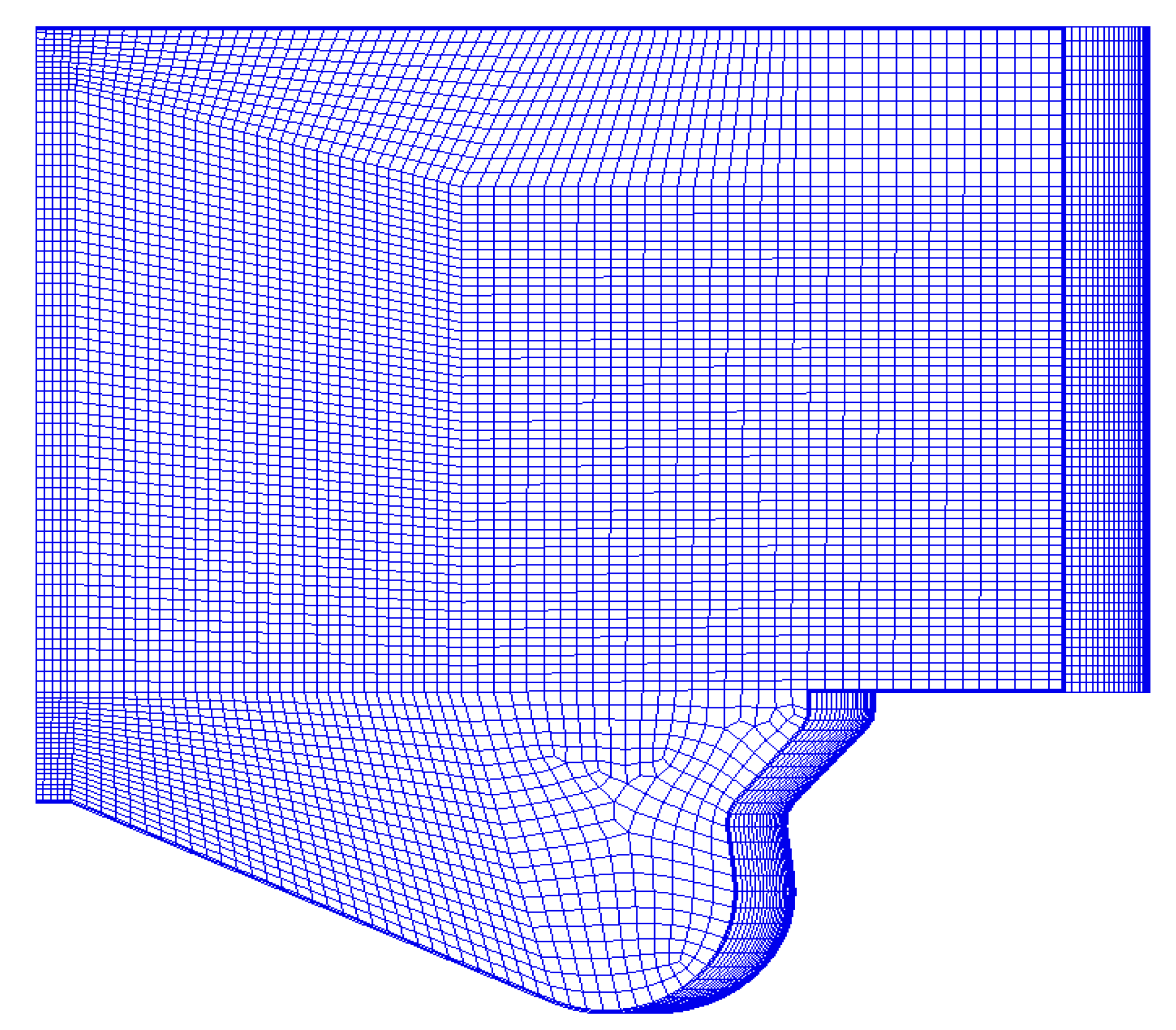
2.2.4. Boundary Condition

To obtain the boundary conditions of 3D calculation, the 1D calculation model is built by AVL-BOOST software. After verifying the results of 1D model calculation with the experiment results and 3D model simulation results, some boundary conditions which are inconvenient to measure are obtained by 1D calculation. For example, the volume, temperature, and pressure of IVC are 249.30 mL, 420 K, and 197.37 kPa, respectively. In addition, some boundary conditions were calculated by the following equations [4]:
(1)
Initial turbulent kinetic energy (TKE) of cylinder:
E T K E = 3 2 × U 0 2 = 3 2 × ( C m 2 ) 2
C m = 2 L ( n 60 )
where U0 is the turbulent fluctuation velocity, m/s.
(2)
Initial cylinder turbulence scale length:
L T S L = L V 2
where Lv is the max. lift of the valve.
(3)
Fuel injection mass per cycle:
V b = b e p e τ n 120 n f ρ F × 10 3
where Vb is the fuel injection mass per cycle, g/cycle; be is the brake specific fuel consumption, g/(kw·h); pe is the power, kW; τn is the number of strokes; nf is the diesel engine speed, r/min; i is the number of cylinders.

3. Engine Setup and Experimental Cases
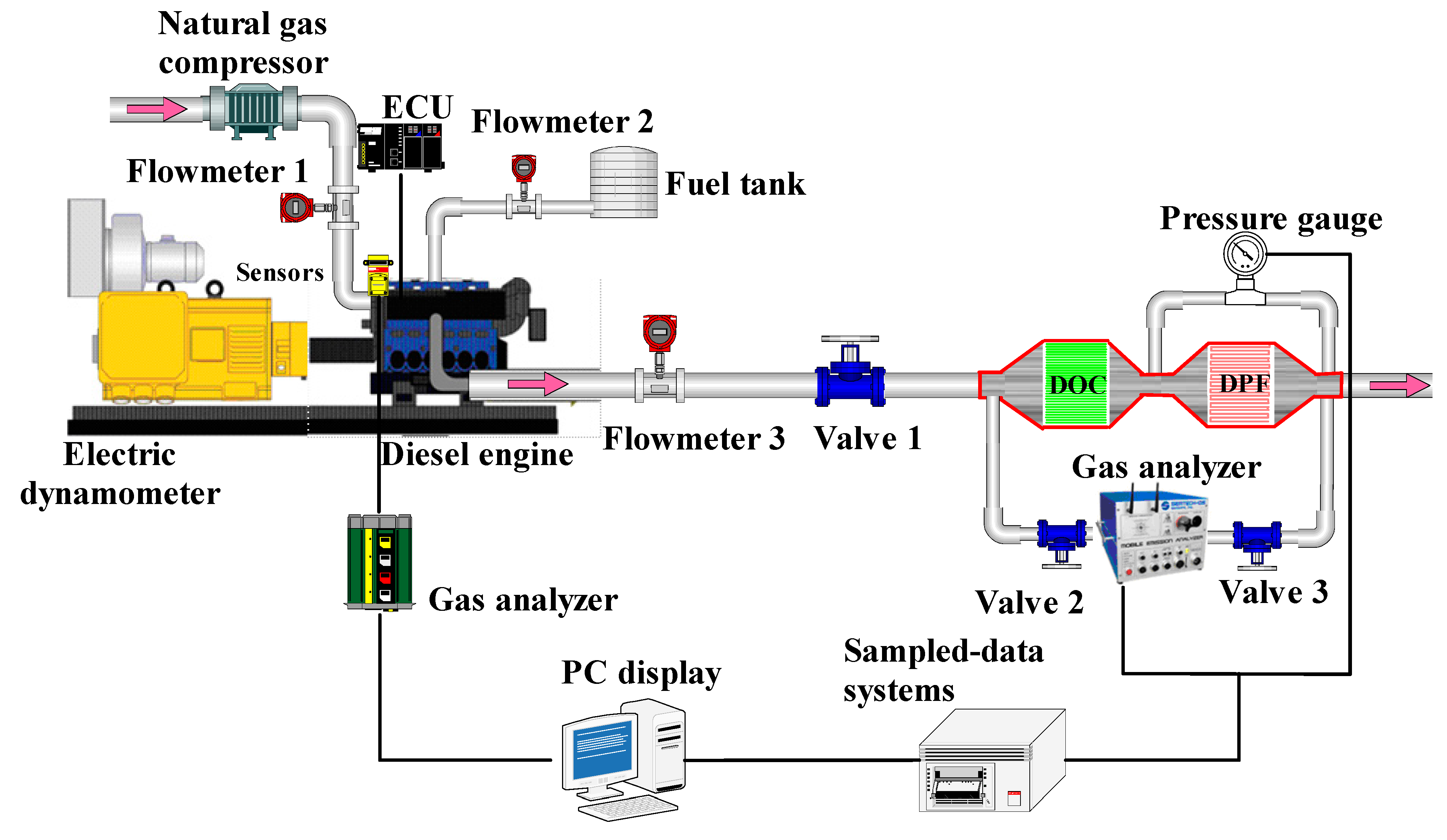
3.1. Engine Setup

The experiment was carried out on a six-cylinder turbocharged intercooled four-stroke diesel engine refitted into a diesel engine. The specific parameters of the engine are shown in Table 1, and the layout of the engine is shown in Figure 3. Among them, the intake system is installed on the intake manifold, and the natural gas enters the cylinder together with the air to form a homogeneous mixture, which can accurately control the injection quantity of NG. The common rail injection system was powered by a high-pressure fuel pump. The improved diesel engine was directly connected with the hydraulic dynamometer. NOx, CO, and HC emissions were measured by Horiba exhaust gas analyzer, the AVL DEWE-2010CA diesel engine combustion monitoring system was adopted, and the electronic unit pump control system was used to accurately control the fuel injection quantity of the engine. In the experiment, the injection pressure of the injector remains constant at 150 MPa. In addition, the diesel and natural gas properties parameters were shown in Table 2.

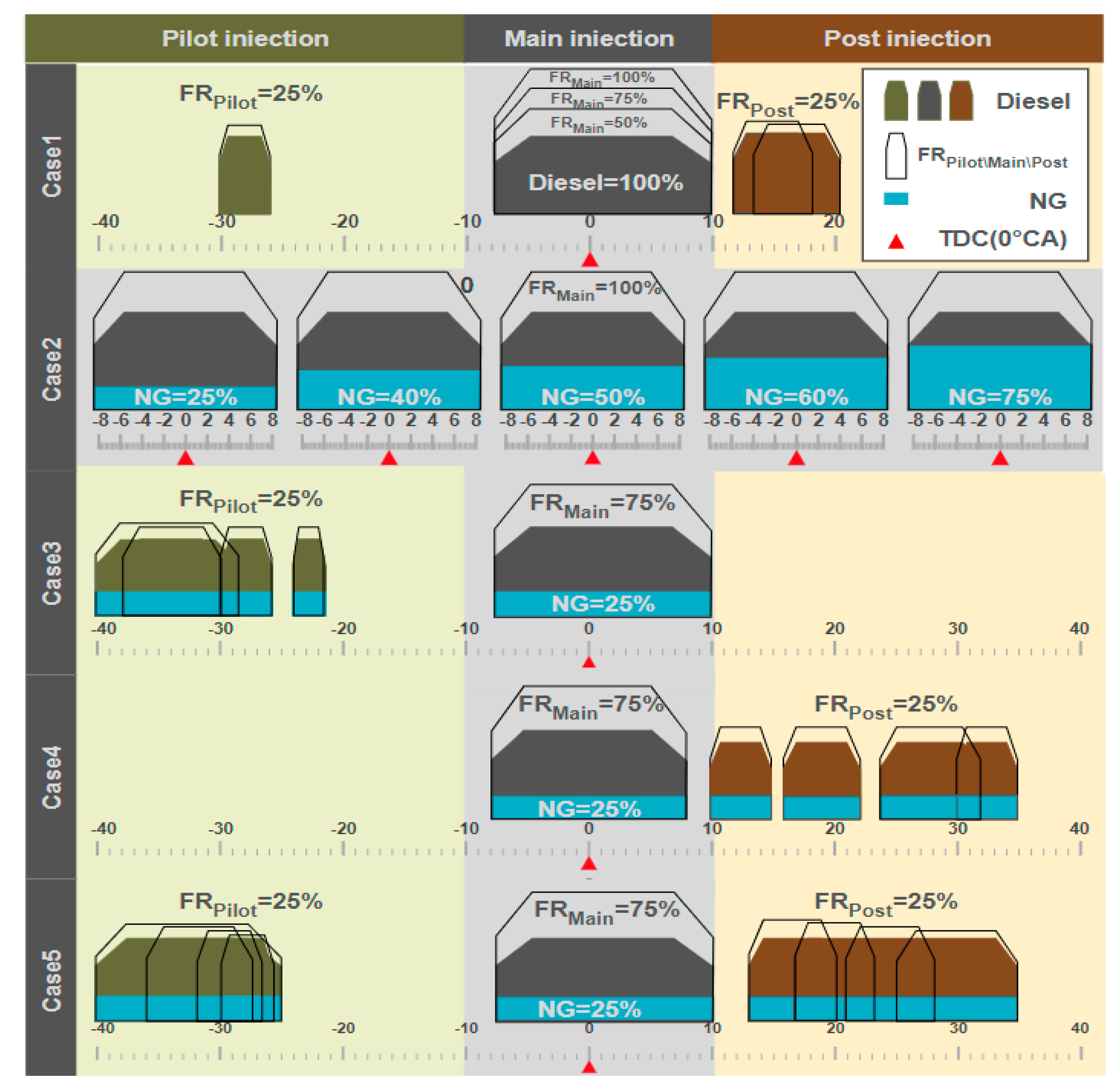
3.2. Experimental Cases

Numerical simulation technology can be used to analyze the combustion process in the cylinder and provide information of intermediate products and related free radicals. In the paper, the process of numerical simulation, which starts from IVC (564 °CA) to EVO (848 °CA) is studied. In the initial stage of the simulation, it was assumed that NG and air were uniformly mixed, and the pressure and temperature of the mixture were also homogeneous. During the experimental process, the engine speed was at the constant speed of 1800 rpm. Then, the cycle simulation under different injection strategies was shown in Figure 4. Among them, Case 1 calculated the results of four injection strategies of pure diesel, while Case 2 calculated the results of single main injection when burning dual fuel with different NG mixing ratios, which were used as the basis of comparative analysis. According to Equation (33), the energy fraction of natural gas is calculated by the low calorific value and mass flow rate of fuel. Similarly, according to Equation (34), the proportion of the mass flow rate of pre injection, main injection, or post injection to the total mass of diesel is calculated.
% N G = M N G L H V N G M N G L H V N G + M D L H V D
% F R = M D - p i l o t , m a i n , p o s t M D - t o t a l
where %NG is the energy fraction of natural gas, %; MNG (respectively, MD) is the mass of NG (respectively, diesel), mg; LHVNG (respectively, LHVD) is the low heat value of NG (respectively, diesel), MJ·kg−1; %FR is the percentage of injection volume consumed by each injection strategy to total cycle injection volume, %; MD-pilot,main,post is the mass of diesel injected for each injection strategy, mg; MD-total is the total mass of diesel injected in cycle, mg.

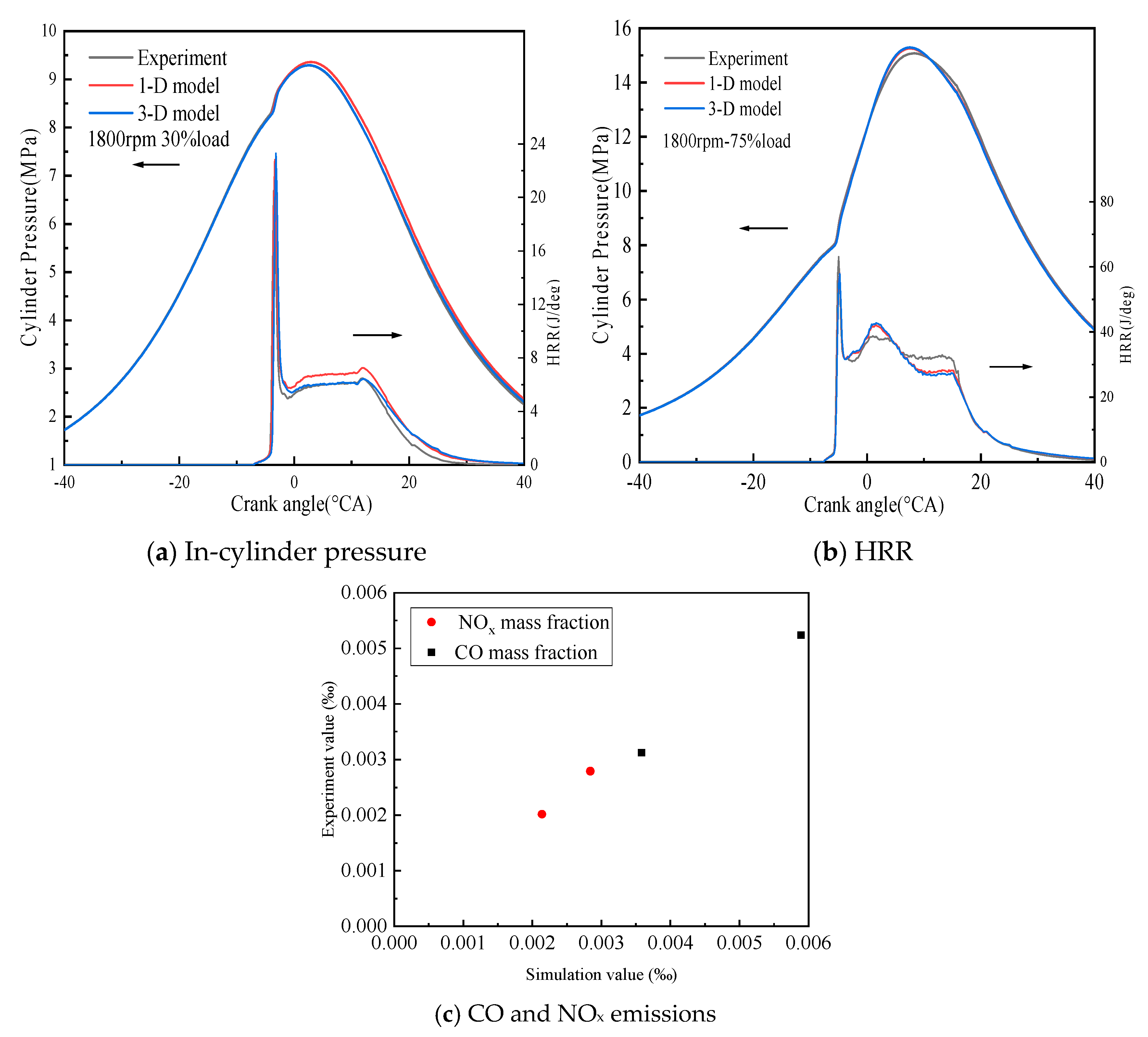
3.3. Model Validation

In AVL-BOOST and AVL-Fire environment, the default codes do not have accurate thermophysical properties, which cannot accurately describe the formation/dissociation of intermediate chemical species, especially for multi component fuels. Therefore, a simplified chemical kinetic mechanism of diesel NG dual fuel is used to calculate the combustion process of cylinder, and the HRR of the 3D CFD simulation is obtained from the reaction heat source term, which is proved by Reference [36]. In addition, the HRR for 1D simulations and experiments can be obtained by the following equation:
d Q T d θ = γ γ 1 p c y d p c y d θ + 1 γ 1 V c y d p c y d θ
where dQT/dθ is the HHR, J/deg; θ is the crankshaft angle, °; pcy is cylinder pressure, MPa; V is cylinder volume, m3; γ is the specific heat capacity, J/(kg·K).
The experiment was carried out on a six-cylinder diesel engine under different load conditions. The cylinder pressure and heat release rate (HRR) from the simulation results were compared with the experimental results and shown in Figure 5. The results show that the cylinder pressure, HRR, NOx, and CO emissions obtained by numerical simulation are in agreement with the experimental results. The maximum error is less than 5%. Therefore, the accuracy of the model is reliable (see Figure 5a–c).

4. Results and Discussion

In the paper, D100 is the pure diesel, D75 is the 25% NG addition blends with 75% diesel by mass; D60 is the 40% NG addition blends with 60% diesel by mass; D50 is the 50% NG addition blends with 50% diesel by mass; D40 is the 60% NG addition blends with 40% diesel by mass; D25 is the 75% NG addition blends with 25% diesel by mass. The results of Case 1 and Case 2 are used as the basis for comparative analysis with Cases 3–5. The effects of different NG mixing ratio, injection strategies (main injection, pilot-main injection, main-post injection, and pilot-main-post injection), pilot injection start time (SODI1), and post injection start time (SODI3) on the combustion and emission characteristics of the diesel NG dual-fuel engine are analyzed. In the pure diesel case, the single-hole cycle fuel injection is 19.60 mg, the start of diesel injection (SODI2) at −8 °CA in the main injection phase, and the injection duration in the main injection phase is constant. In the cases of the subsequent addition of NG, the fuel mass of the pre-injection, main injection, and post-injection is controlled by adjusting the injection duration.
In the process of simulation calculation, the deflagration will easily occur when the main injection time is set too early in the dual fuel mixed combustion case [34]. It is due to the fact that the chemical reaction sensitivity of the mixture in the cylinder increases when NG is added into the homogeneous mixture. If the injection advance angle is earlier, the combustion in the cylinder will release heat prematurely. Due to the effects of heat conduction and heat radiation, the combustible mixture in some areas of the cylinder will reach the ignition point before the flame spreads. It leads to a sudden increase in regional pressure and temperature. Thus, based on the previous research experiences [36], the main injection time was set at −8 °CA ATDC.

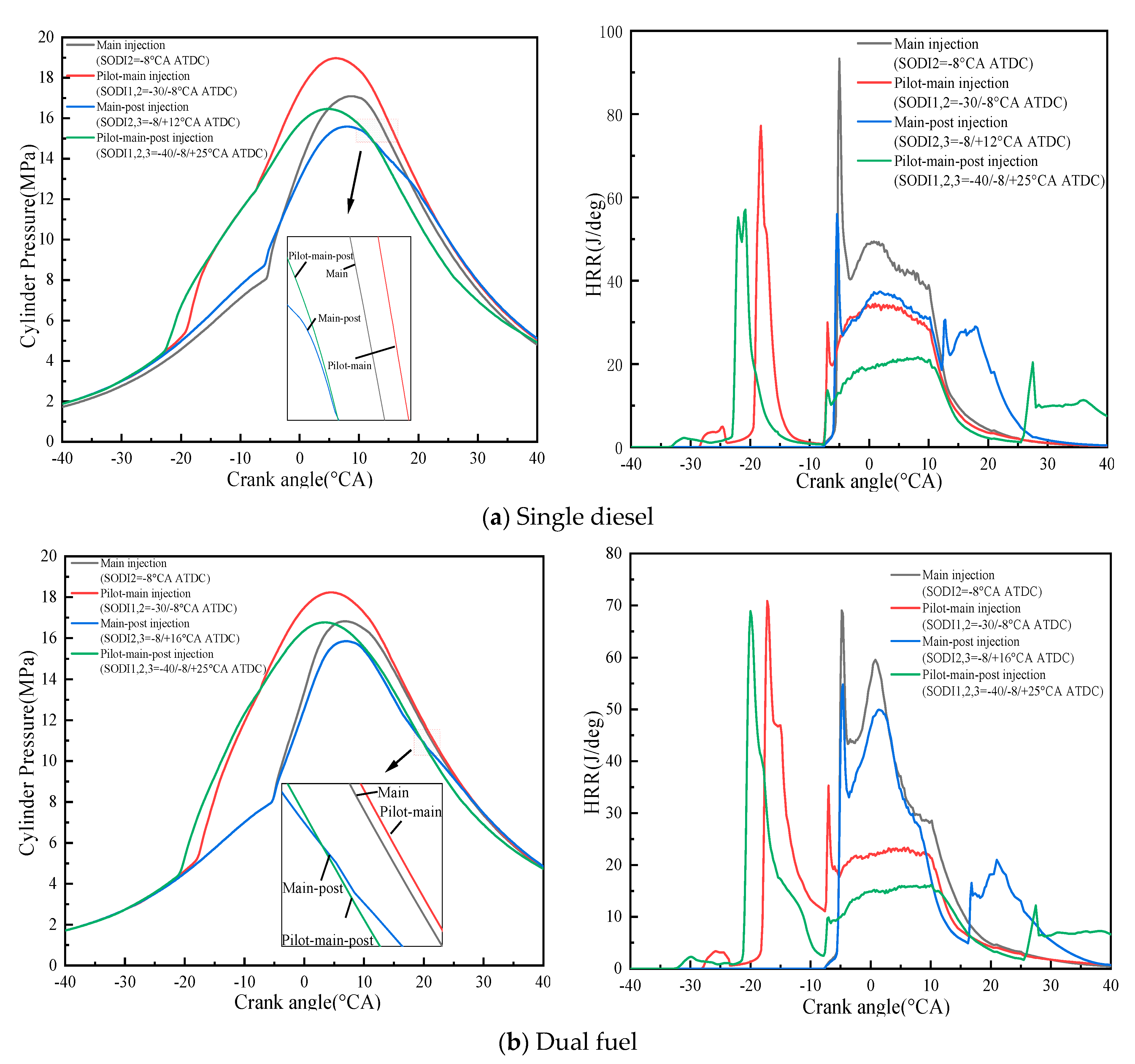
4.1. Combustion Characteristics

Figure 6a–c shows the cylinder pressure and HRR of the pure diesel case and the dual-fuel case with different NG mixing ratios. It can be seen that pure diesel (D100) has the highest peak cylinder pressure, followed by D75, D60, D50, D40, and D25. Based on the analysis of the HRR, the diesel injection time in the pure diesel case is earlier than that in the dual-fuel case. In Figure 6a, the cylinder pressure will be higher in the condition of the ahead-of-time heat release and the combustion phase, and more sufficient combustion in the compression stroke. In addition, as the proportion of NG mixing increases, the cylinder peak pressure generally shows a decreasing trend. It is due to the fact that NG and air are introduced into the cylinder in the form of a homogeneous mixture. As the proportion of NG increases, the excess air coefficient and the intake air volume decrease. Moreover, as the mixing ratio of NG increases, the amount of diesel injected into the cylinder will also decrease, and the spread speed of the flame will be slowed down, resulting in a low initial HRR. The pressure and temperature decrease accordingly in the initial combustion stage. Similarly, other studies had the same results [46,47].
In Figure 6b, it can be seen that as the NG mixing rate increases, the spontaneous combustion of diesel is suppressed, although the amount of NG involved in the premixed combustion stage increases. This leads to a significant trend of decreasing the peak HRR in the diffusion combustion phase, and as the NG mixing rate continues to increase, the combustion delay also gradually increases, D100 has the smallest ignition delay angle, followed by D75, D60, D50, D40, and D25. It is due to the fact that the increase of the NG mixing ratio, resulting in a decrease in the overall fuel activity, the combustion start angle is delay and combustion end angle is advance, more fuel burning after the TDC. When the NG mixture ratio is 75%, a significant increase in ignition delay angle is observed.
Figure 7 and Figure 8 show the in-cylinder temperature distribution and diesel distribution at different NG mixing ratios. It can be seen that the diesel injection time in the pure diesel case is earlier than that of the dual fuel, and a better-atomized fuel is formed at −6 °CA ATDC. As the NG fraction in dual-fuel increases, the lag time of diesel injection increases. Thus, the fuel atomization time was also delayed correspondingly. It can be seen that the premixed combustion in the cylinder is over, and the diffusion combustion phase has been entered at the time of TDC when the diesel fraction is high. Similarly, the start of premixed combustion is relatively late in dual fuel with a high NG fraction. In addition, it can be found that it is basically at the stage where the average temperature of combustion in the cylinder is the highest at the 15.7 °CA ATDC. With the increase of NG mixing proportion in dual fuel, the high-temperature area in the cylinder distributes more widely, resulting in a higher average temperature in the cylinder.
Figure 9 shows the cylinder pressure and HRR in the cylinder with a single main injection and pilot-main injections at different SODI1. When the SODI1 at −30 °CA ATDC, the peak pressure increases from 16.8 MPa to 18.6 MPa compared with the single main injection. There is an increase of about 10.7% (See Figure 9a). However, when SODI1 further advances from −30 °CA ATDC to −38 °CA ATDC and −40 °CA ATDC, the peak pressure in cylinder decreases and the ignition delay angle is further reduced. Based on the analysis of the HRR, it is obvious that compared with a single main injection, the pilot-main injection strategy improves the combustion and increases the peak pressure in the cylinder (See Figure 9b). With the advancement of the SODI1, the cylinder pressure and the peak HRR both show a trend of first increase and then decrease. It is due to the fact that the in-cylinder mixture is mixed more fully with the advance of the SODI1, increasing the chemical sensitivity of the fuel. Therefore, the heat release advance and accompany by low temperature heat release (LTHR), the combustion delay angle of the diffusion combustion phase is reduced, as the SODI1 continuously advance, the combustion delay angle further decreases, keeps the main combustion close to the TDC.
Figure 10 shows the cylinder pressure and HRR with single main injection and main-post injection strategy at different SODI3. It can be seen that compared with single main injection, the peak pressure in the cylinder and the peak HRR are reduced. With the delay of the SODI3, there is no effect on the peak cylinder pressure in the diffusion combustion stage, but the peak HRR decreases, the post-injection diesel slightly increases the heat release in the later combustion stage. With the SODI3 from +10 °CA ATDC delay to +30 °CA ATDC, the peak pressure in cylinder changes little, because SODI3 has no effect on the combustion start stage (i.e., premixed combustion process), but the peak HRR is significantly lower. It is due to the fact that only 75% of the original fuel injection in the main injection phase and 25% of diesel in post injection is injected to cylinder, not conducive to the premixed combustion and diffusion combustion.
Figure 11 shows the cylinder pressure and HRR with single main injection and pilot-main-post injection strategy with different SODI1 and SODI3. It can be seen that the peak pressure in the cylinder and the peak HRR is slightly higher than that of single main injection. With the advance of the SODI1 and the delay of the SODI3, the peak cylinder pressure and the peak HRR both show a trend of first increase and then decrease, the post-injection diesel slightly increases the heat release in the later combustion stage. It is due to the fact that the pilot injection makes the mixture mix better, promotes the heat release in advance, reduces the combustion delay angle, and facilitates the premixed and diffusion combustion, main combustion close to the TDC. At the same time, the increase in peak pressure and peak HRR can be seen that pilot injection has a greater effect on engine combustion compared to post injection.
Figure 12a shows the cylinder pressure and HRR of pure diesel and dual fuel (75% diesel25% NG) with four different injection strategies, respectively. The results show that the effects of different injection strategies on the combustion characteristics of pure diesel and dual fuel are the same. Figure 12b further confirms the previous simulation results. In-cylinder temperature distribution field with different fuel injection strategies is shown as Figure 13. Adding a pilot injection at −30 °CA ATDC before the single main injection can significantly increase the cylinder peak pressure and peak HRR, advance the heat release and reduce the ignition delay angle. Adding a post-injection at +30 °CA ATDC after the single main injection will result in a decrease in the peak pressure and peak HRR. In addition, the pilot-main-post injection strategy can slightly increase the peak pressure in the cylinder and peak HRR, which also advance the heat release and reduce the ignition delay angle.

4.2. Emission Characteristics
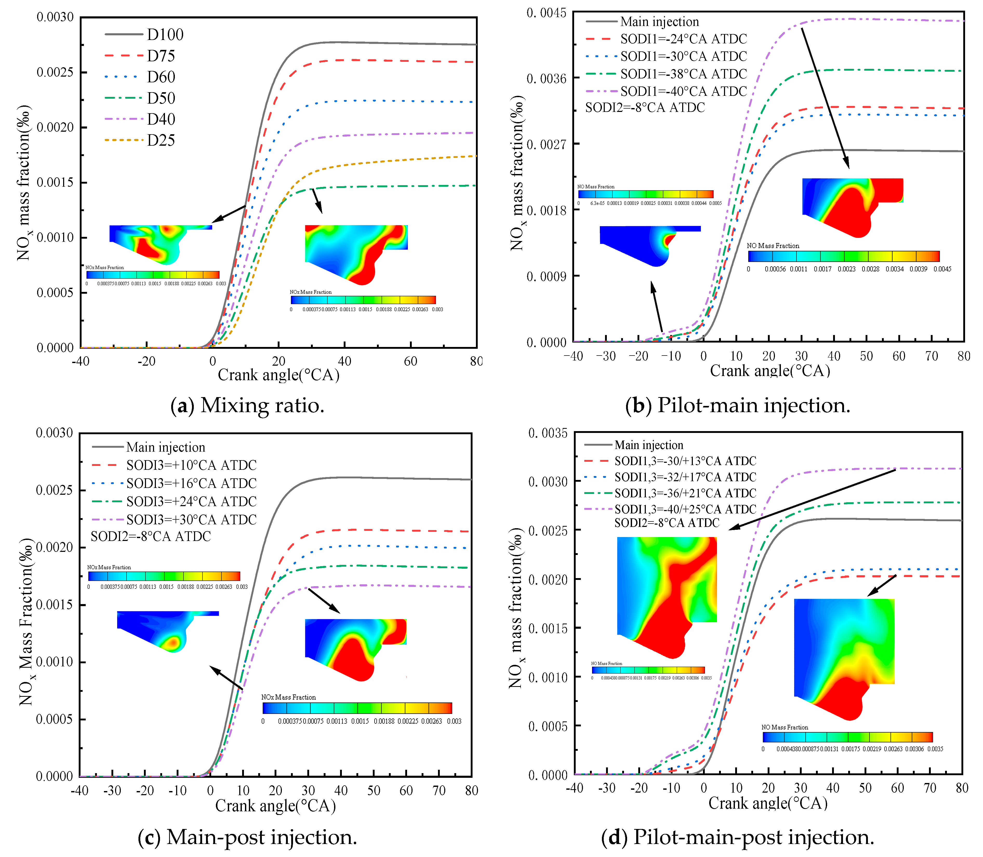
4.2.1. NOx Emission

Figure 14 shows the NOx emissions with different NG mixing ratios and different diesel injection strategies. It can be seen that the NOx formation increases rapidly between 0 and 30 °CA ATDC. Compared with the pure diesel case, the combustion of dual fuel can significantly reduce NOx emission. Moreover, NOx emission firstly decreases and then increases with the increase of the mixing ratio of NG. For example, compared with pure diesel case, NOx emission of D50 is reduced by 47%. In addition, when the proportion of NG in dual-fuel increases from 50% to 60%, NOx emission increase by 24%. It is due to the high temperature caused by the improved combustion. With the increase of the NG mixing ratio, the mixture fuel in the cylinder is fully mixed and the combustion process a is more complete and rapid.
Figure 14b shows the NOx emission with the pilot-main strategy. It can be seen that the pilot-main injection strategy can greatly increase NOx emission. In addition, NOx emissions show an increasing trend with the increase of the SODI1. Compared with main injection, the NOx emission of pilot injection increase by 65.3% when the advance angle is −40 °CA ATDC. It is due to the high temperature caused by the increased advance angle. The high temperature is beneficial to the formation of NOx.
Figure 14c shows the NOx emission with the main-post injection strategy. It can be seen that the main-post injection strategy can reduce NOx emission compared with main injection strategy. With the increase of SODI3, the NOx emission firstly decreases and then increases. Compared with main injection, the NOx emission of main-post injection strategy increases by 29.6%when the advance angle is +24 °CA ATDC. In addition, NOx emission decreases by 7.6% when the SODI3 delay is from +24 °CA ATDC to +30 °CA ATDC. It is due to the fact that only 75% of the original fuel injection in the main injection phase and 25% of diesel in post-injection phase is injected to cylinder. Thus, it significantly reduces the temperature in the cylinder during the main fuel injection phase, thereby inhibiting the generation of NOx.
Figure 14d shows the NOx emission with pilot-main-post injection strategy. It can be seen that the NOx emission firstly decreases and then increases with increase of advance angle. It is due to the fact that the increase of pilot injection and post injection. Only 50% original diesel is injected to cylinder in the main injection phase. However, when the advance angle of the SODI1 and the delay time of the SODI3 further increase, the sufficient pre-mixing allows the mixture to be widely distributed in the cylinder. After being ignited by diesel, the cylinder was filled with high-temperature gas, which greatly result in the increase of NOx emission.

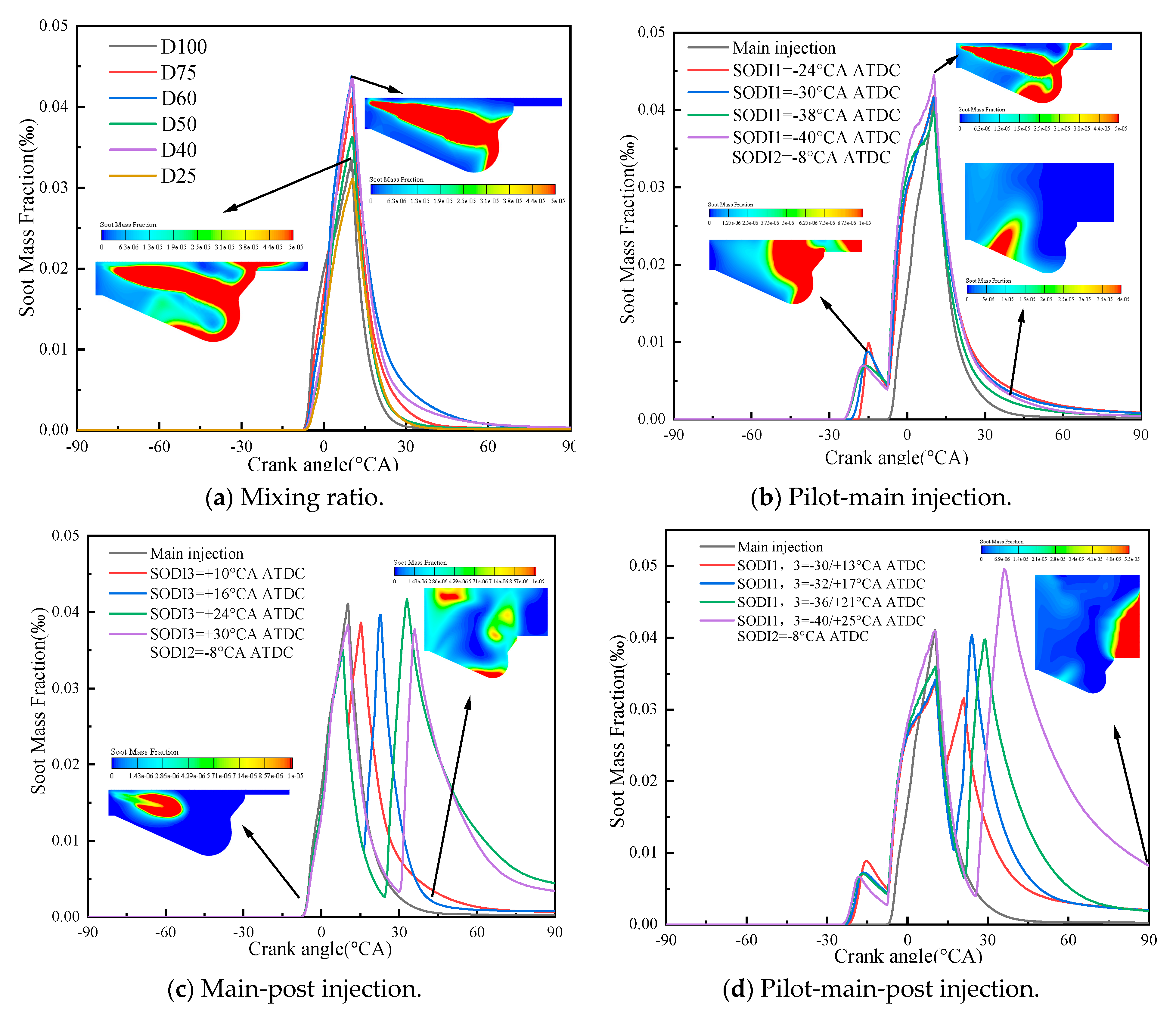
4.2.2. Soot Emission
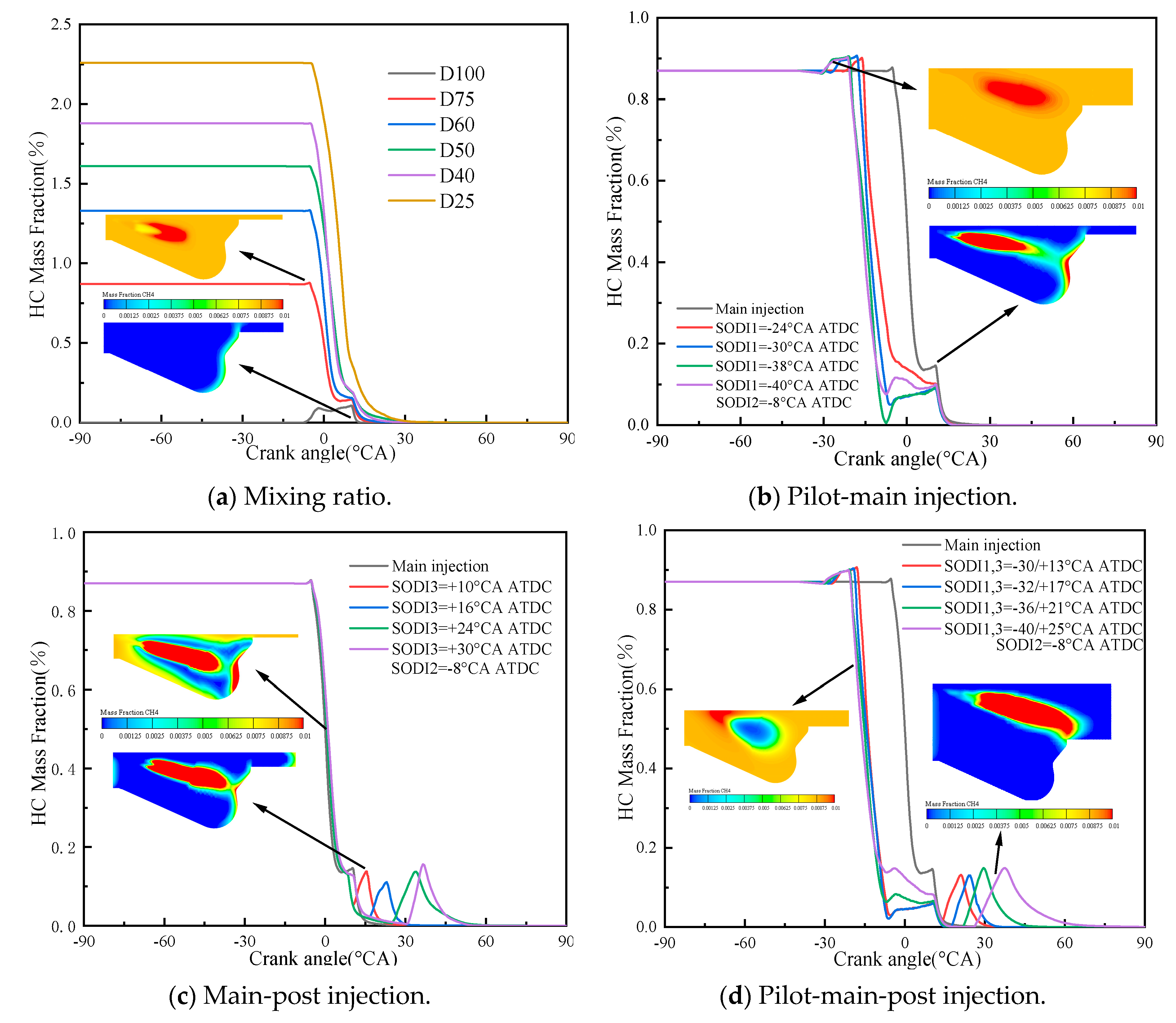
The multiple injection technology not only improves the combustion process, but also reduces the pollutant emissions, and optimizes the trade-off relationship between soot and NOx [32]. Figure 15 shows the soot emission with different NG mixing ratios and different fuel injection strategies. It can be found that the soot mass fraction in the cylinder firstly increases and then decreases with the increase of NG mixing ratio. The soot emission reaches the highest and lowest when the ratio of NG is 60% and 75%, respectively. The soot emission is mainly distributed in the high temperature and oxygen-poor area, and then gradually reduced by oxidation. With the addition of pilot injection and post injection, the emission of soot changes from a single peak of the main injection to a double peak. When there is no pilot injection, soot emission is mainly distributed in the front of the combustion chamber. However, in the pilot injection and post injection stage, soot is mainly generated at the bottom and rear of the combustion chamber. The use of pilot-main injection will slightly increase the emission of soot. It is due to the fact that the amount of fuel injected in the pilot injection stage is less, and the local high temperature generated by combustion and the oxygen-deficient environment in the middle of the fuel beam create conditions for soot generation. When the pilot-main-post injection strategy was adopted, the emission curve of soot shows three peaks, and the three peaks show a trend of first decreases and then increases with the advance of the SODI1 and the delay of the SODI3. From the changing trend, it can be seen that the SODI3 has a greater impact on this strategy.

4.2.3. HC Emission

Figure 16 shows the HC emission and methane distribution with different NG mixing ratios and injection strategies. Figure 16a shows that the HC emission firstly increases in the initial stage and then decreases with the increase of NG mixing ratio. Compared with pure diesel, the NG mixing generated more HC in the early stage. However, a large amount of HC was oxidized at −8 °CA ATDC. As seen in Figure 16b, the NG combustion can be clearly promoted by using the pilot-main injection strategy. Some previous studies have found that the main source of HC emission is the incomplete combustion of dual fuel. The combustion phase was also advanced with the increase of SODI1. Thus, more HC will be oxidized. As seen in Figure 16c, it can be seen that the NG combustion rate decreases with the main-post injection strategy. As the post injection diesel enters the cylinder, the HC emission will appear a second small peak at the back. It is due to the fact that the reduction in injection mass leads to the decrease of in cylinder temperature in the main combustion stage and the increase of incompletely burned NG. Figure 16d shows that the pilot-main-post injection strategy improves the combustion and accelerates the combustion rate of NG, but the post injection diesel also forms a second HC emission peak. In addition, Figure 17 shows the combustion rate of CH4 under different injection strategies. It can be seen that the pilot-main injection and pilot-main-post injection strategies can advance the combustion of CH4 and make it burn more fully at TDC. On the contrary, the main-post injection is not conducive to the combustion of CH4 in cylinder.

4.2.4. CO Emission

CO is a kind of intermediate product, which is mainly caused by the incomplete combustion due to the low temperature and lack of oxygen in some areas during in-cylinder combustion. Figure 18 shows the CO emission under different NG mixing ratios and injection strategies. It can be seen that the CO emission is significantly reduced with the increase of NG mixing ratio in the early stage. It is due to the fact that the higher concentration of NG is helpful to combustion, the higher temperature in the cylinder, and the more abundant positive gas are conducive to the conversion of CO into CO2. Figure 18b–d show that the pilot-main injection, main-post injection, and pilot-main-post injection strategies of can further reduce the CO emission in the early stage. It is due to the improved combustion caused by the NG in dual fuel. At TDC, CO mainly distributed in the outer region of diesel injection trajectory, where the fuel concentration was high and the oxygen was poor. In addition, when the injection advance angle decreases, the CO emission increases. It is due to the fact that the fuel injected later does not have enough time to oxidize.

5. Conclusions

With the continuous deterioration of energy crisis [48,49,50,51,52,53,54,55] and environmental problems [56,57,58,59,60,61,62], finding effective methods to optimize the combustion of internal combustion engine and reduce emission has become the research focus. However, the fuel injection strategies play an important role in improving performance and reducing emission. Therefore, this paper studied the mixing ratio and the different injection strategies (i.e., main injection, pilot-main injection, main-post injection, and pilot-main-post injection) on the combustion and emission characteristics of diesel NG dual-fuel engine. The main conclusions are as follows:
(1)
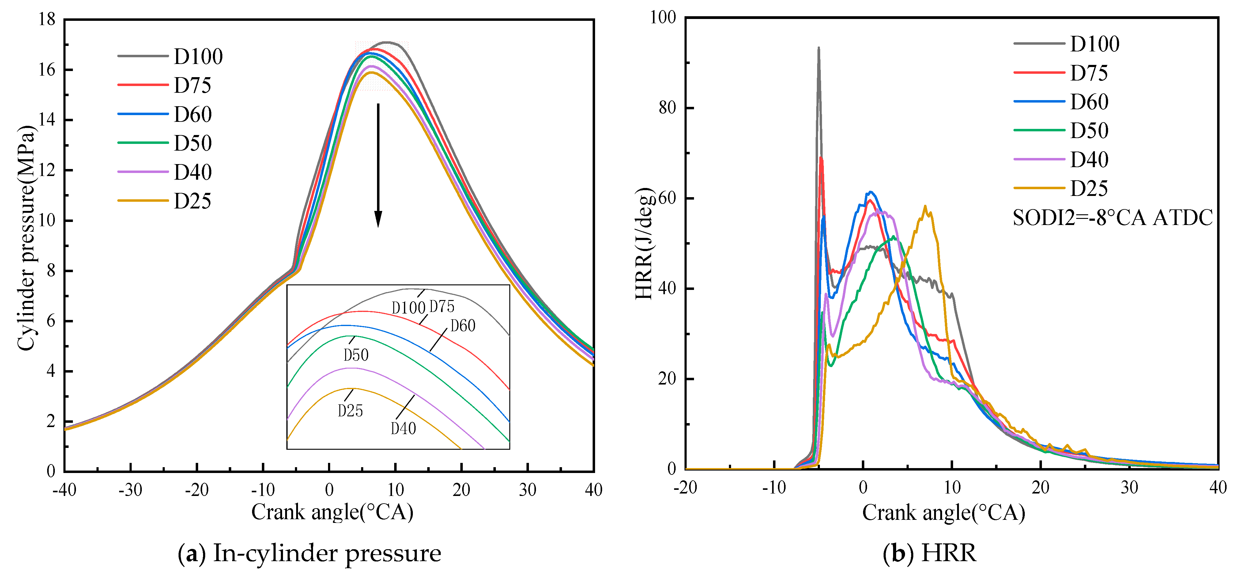
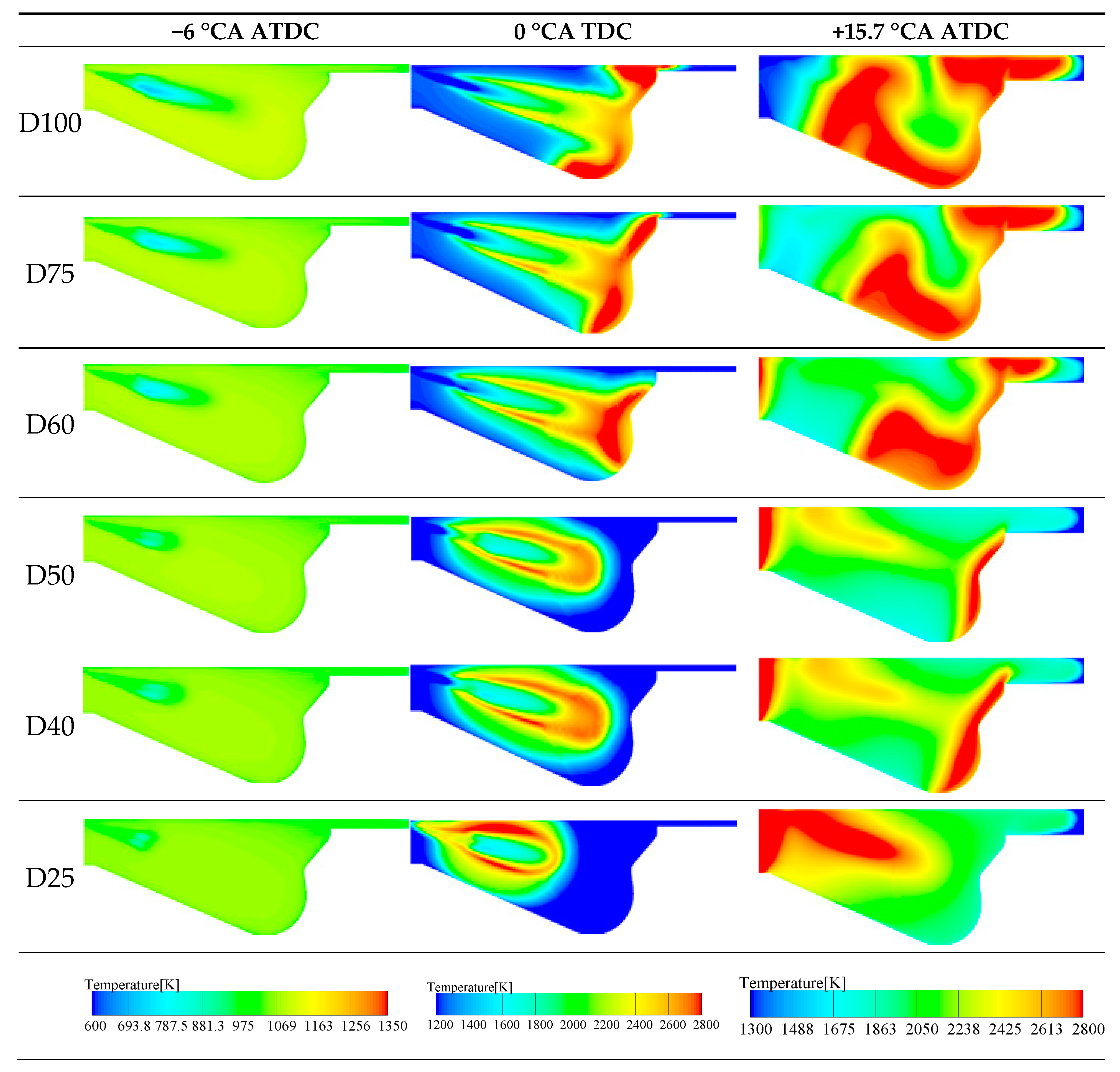
With the increase of NG mixing ratio, the max. cylinder pressure is reduced, but the cylinder temperature is increased. In addition, the NOx and CO emission are reduced. When the NG mixing ratio is 50%, the NOx and CO emission are reduced by 47% and 45%, respectively. However, the HC emission increases.
(2)
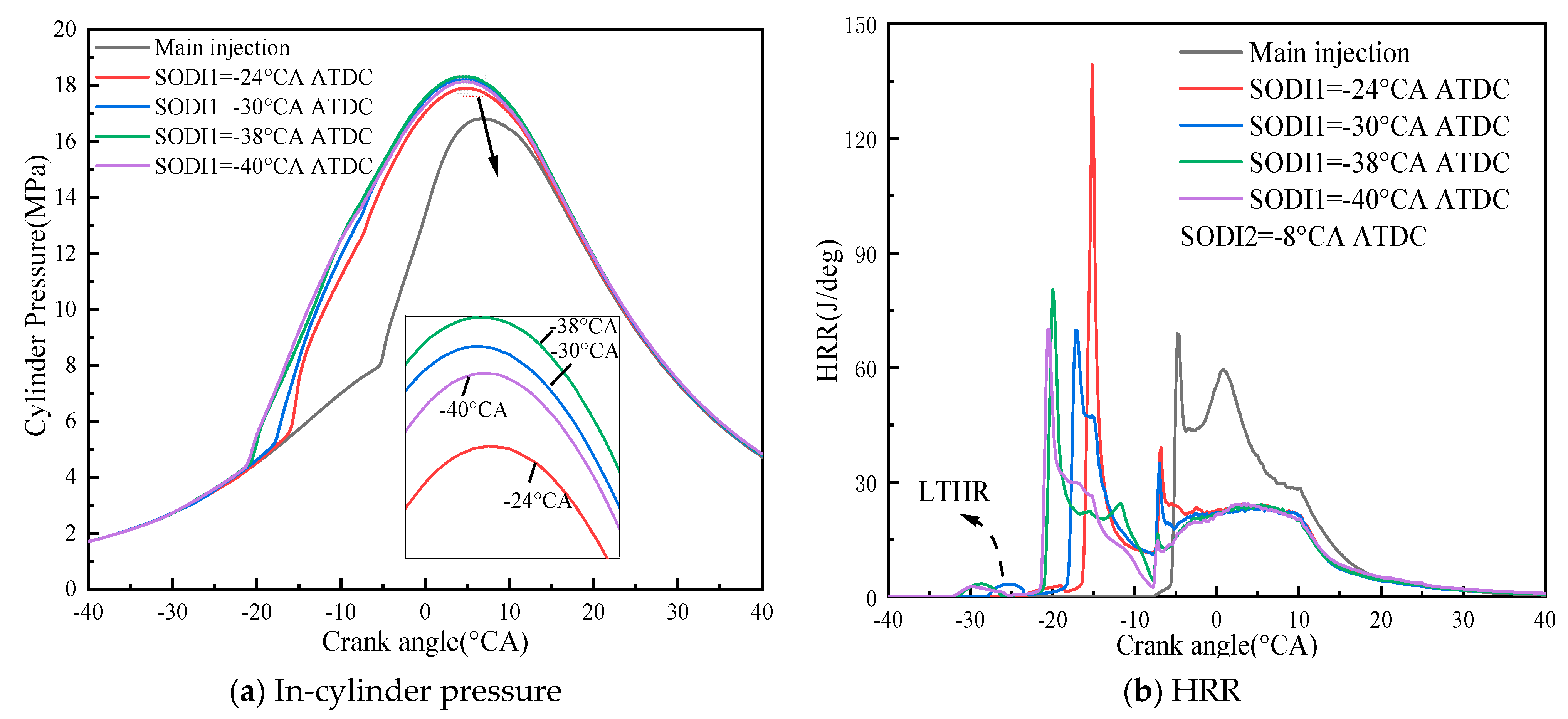
Compared with the single main injection, the pilot-main injection strategy can significantly improve the cylinder pressure and HRR. When the SODI1 is −30 °CA ATDC, the cylinder pressure increases by 19.6% and the cylinder temperature also increases by 4.6%. In terms of emission, the pilot-main injection can significantly reduce HC and CO in the cylinder. The soot emission firstly decreases and then increases, but NOx emission increases, when SODI1 is −38 °CA ATDC.
(3)
Compared with the single main injection, the main-post injection strategy can reduce the cylinder pressure and HRR. However, the cylinder temperature is reduced in the main injection stage. The NOx and CO emissions is reduced. When the SODI3 is 24 °CA ATDC, the NOx emission is reduced by 29.6%.
(4)
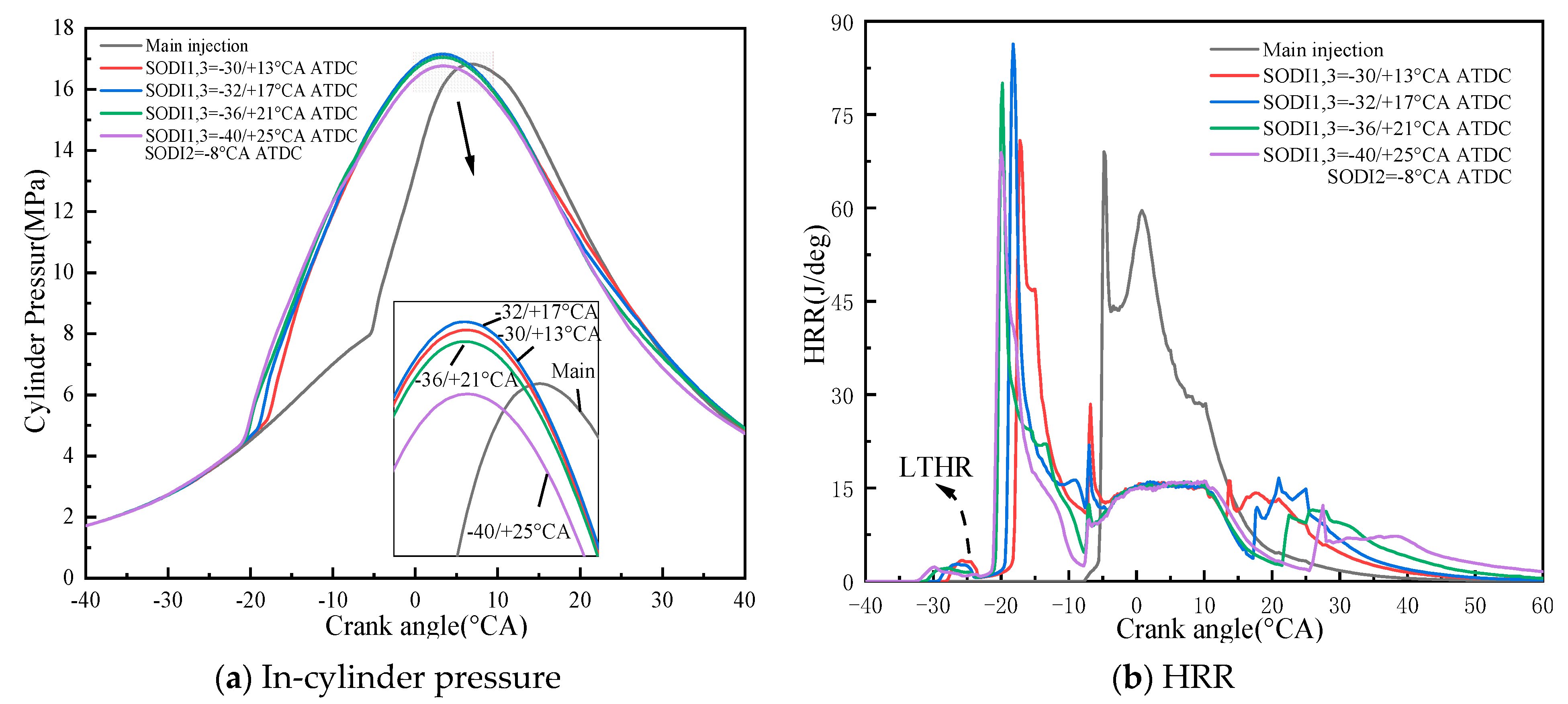
Compared with the single main injection, the pilot-main-post injection strategy slightly increase the cylinder pressure, HRR, and cylinder temperature. In terms of emission, it can effectively reduce the HC and CO emission. Due to the effects of pilot injection and post injection of diesel, the soot emission in cylinder increases, but the NOx emission in cylinder firstly decreases and then increases.

Author Contributions

Conceptualization, J.L., Z.Z. and S.C.; methodology, H.C, Z.Z. and S.C.; software, Z.L., J.W.; validation, J.L., Z.L. and B.Q.; formal analysis, J.L., Z.Z. and S.C.; investigation, J.L., H.C. and S.C.; resources, J.L. and S.C.; data curation, J.L.; writing—original draft preparation, J.L., Z.L. and S.C.; writing—review and editing, J.L., Z.L., H.C. and S.C.; visualization, J.L. and S.C.; supervision, J.L. and S.C.; project administration, Z.Z. and S.C.; funding acquisition, Z.Z. All authors have read and agreed to the published version of the manuscript.

Funding

This work is supported by the Guangxi Basic Ability Improving Program of 2020KY08015, the Natural Science Foundation of Guangxi under the research grant 2018GXNSFAA294122; the Guangxi Special Program for Young Talents Guike(AD20159066) and the Guangxi University of Science and Technology Doctoral Fund under the research grants of 20Z22 and 20S04.

Data Availability Statement

All data used to support the findings of this study are included within the article.

Conflicts of Interest

The authors declare that they have no conflict of interest regarding the publication of this paper.

References

  1. Payri, F.; López, J.J.; Martín, J.; Carreño, R. Improvement and application of a methodology to perform the Global Energy Balance in internal combustion engines. Part 1: Global Energy Balance tool development and calibration. Energy 2018, 152, 666–681. [Google Scholar] [CrossRef]
  2. McClellan, R.O.; Hesterberg, T.W.; Wall, J.C. Evaluation of carcinogenic hazard of diesel engine exhaust needs to consider revolutionary changes in diesel technology. Regul. Toxicol. Pharmacol. 2012, 63, 225–258. [Google Scholar] [CrossRef] [Green Version]
  3. Cai, T.; Becker, S.; Wang, B.; Tang, A.; Fu, J.; Han, L.; Sun, Y.; Zhao, D. NO emission performance assessment on a perforated plate-implemented premixed ammonia-oxygen micro-combustion system. Chem. Eng. J. 2021, 417, 128033. [Google Scholar] [CrossRef]
  4. Zhang, Z.; Jiaqiang, E.; Chen, J.; Zhu, H.; Zhao, X.; Han, D.; Zuo, W.; Peng, Q.; Gong, J.; Yin, Z. Effects of low-level water addition on spray, combustion and emission characteristics of a medium speed diesel engine fueled with biodiesel fuel. Fuel 2019, 239, 245–262. [Google Scholar] [CrossRef]
  5. Cai, T.; Zhao, D.; Sun, Y.; Ni, S.; Li, W.; Guan, D.; Wang, B. Evaluation of NO emissions characteristics in a CO2-Free micro-power system by implementing a perforated plate. Renew. Sustain. Energy Rev. 2021, 145, 111150. [Google Scholar] [CrossRef]
  6. Zhang, Z.; Ye, J.; Tan, D.; Feng, Z.; Luo, J.; Tan, Y.; Huang, Y. The effects of Fe2O3 based DOC and SCR catalyst on the combustion and emission characteristics of a diesel engine fueled with biodiesel. Fuel 2021, 290, 120039. [Google Scholar] [CrossRef]
  7. Lešnik, L.; Kegl, B.; Torres-Jiménez, E.; Cruz-Peragón, F. Why we should invest further in the development of internal combustion engines for road applications. Oil Gas Sci. Technol. Rev. IFP Energ. Nouv. 2020, 75, 56. [Google Scholar] [CrossRef]
  8. Guo, C.; Zuo, Z.; Feng, H.; Roskilly, T. Advances in free-piston internal combustion engines: A comprehensive review. Appl. Therm. Eng. 2021, 189, 116679. [Google Scholar] [CrossRef]
  9. Jiaqiang, E.; Zhang, Z.; Chen, J.; Pham, M.; Zhao, X.; Peng, Q.; Zhang, B.; Yin, Z. Performance and emission evaluation of a marine diesel engine fueled by water biodiesel-diesel emulsion blends with a fuel additive of a cerium oxide nanoparticle. Energy Convers. Manag. 2018, 169, 194–205. [Google Scholar]
  10. Zhao, D.; Ji, C.; Li, X.; Li, S. Mitigation of premixed flame-sustained thermoacoustic oscillations using an electrical heater. Int. J. Heat Mass Transf. 2015, 86, 309–318. [Google Scholar] [CrossRef]
  11. Peng, Q.; Yang, W.M.; Jiaqiang, E.; Li, Z.; Xu, H.; Fu, G.; Li, S. Investigation on H2/air combustion with C3H8 addition in the combustor with part/full porous medium. Energy Convers. Manag. 2021, 228, 113652. [Google Scholar] [CrossRef]
  12. Zhao, D.; Gutmark, E.; Goey, P. A review of cavity-based trapped vortex, ultra-compact, high-g, inter-turbine combustors. Prog. Energy Combust. Sci. 2018, 66, 42–82. [Google Scholar] [CrossRef] [Green Version]
  13. Zhang, Z.; Jiaqiang, E.; Deng, Y.; Pham, M.; Zuo, W.; Peng, Q.; Yin, Z. Effects of fatty acid methyl esters proportion on combustion and emission characteristics of a biodiesel fueled marine diesel engine. Energy Convers. Manag. 2018, 159, 244–253. [Google Scholar] [CrossRef]
  14. Cai, T.; Zhao, D. Effects of fuel composition and wall thermal conductivity on thermal and NOx emission performances of an ammonia/hydrogen-oxygen micro-power system. Fuel Process. Technol. 2020, 209, 106527. [Google Scholar] [CrossRef]
  15. Pischinger, S. Current and Future Challenges for Automotive Catalysis: Engine Technology Trends and Their Impact. Top. Catal. 2016, 59, 834–844. [Google Scholar] [CrossRef]
  16. Zhang, J.-H.; Chen, M. Assessing the impact of China’s vehicle emission standards on diesel engine remanufacturing. J. Clean. Prod. 2015, 107, 177–184. [Google Scholar] [CrossRef]
  17. Czech, R.; Zabochnicka-Świątek, M.; Świątek, M.K. Air pollution as a result of the development of motorization. Glob. Nest J. 2020, 22, 220–230. [Google Scholar]
  18. Teixeira, A.C.R.; Machado, P.G.; Collaço, F.M.D.A.; Mouette, D. Alternative fuel technologies emissions for road heavy-duty trucks: A review. Environ. Sci. Pollut. Res. 2021, 28, 20954–20969. [Google Scholar] [CrossRef] [PubMed]
  19. Jiaqiang, E.; Zhao, X.; Qiu, L.; Wei, K.; Zhang, Z.; Deng, Y.; Han, D.; Liu, G. Experimental investigation on performance and economy characteristics of a diesel engine with variable nozzle turbocharger and its application in urban bus. Energy Convers. Manag. 2019, 193, 149–161. [Google Scholar]
  20. Peng, Q.; Yang, W.M.; Jiaqiang, E.; Li, S.; Li, Z.; Xu, H.; Fu, G. Effects of propane addition and burner scale on the combustion characteristics and working performance. Appl. Energy 2021, 285, 116484. [Google Scholar] [CrossRef]
  21. Zhao, J.; Zhang, Y.; Chang, J.; Peng, S.; Hong, N.; Hu, J.; Lv, J.; Wang, T.; Mao, H. Emission characteristics and temporal variation of PAHs and their derivatives from an ocean-going cargo vessel. Chemosphere 2020, 249, 126194. [Google Scholar] [CrossRef] [PubMed]
  22. Jiaqiang, E.; Liu, G.; Zhang, Z.; Han, D.; Chen, J.; Wei, K.; Gong, J.; Yin, Z. Effect analysis on cold starting performance enhancement of a diesel engine fueled with biodiesel fuel based on an improved thermodynamic model. Appl. Energy 2019, 243, 321–335. [Google Scholar]
  23. Lee, J.; Park, C.; Bae, J.; Kim, Y.; Lee, S.; Kim, C. Comparison between gasoline direct injection and compressed natural gas port fuel injection under maximum load condition. Energy 2020, 197, 117173. [Google Scholar] [CrossRef]
  24. Yang, Z.; Tate, J.E.; Morganti, E.; Shepherd, S.P. Real-world CO2 and NOX emissions from refrigerated vans. Sci. Total Environ. 2021, 763, 142974. [Google Scholar] [CrossRef] [PubMed]
  25. Kim, W.; Park, C.; Bae, C. Characterization of combustion process and emissions in a natural gas/diesel dual-fuel compression-ignition engine. Fuel 2021, 291, 120043. [Google Scholar] [CrossRef]
  26. Lee, S.; Kim, C.; Lee, S.; Oh, S.; Kim, J.; Lee, J. Characteristics of non-methane hydrocarbons and methane emissions in exhaust gases under natural-gas/diesel dual-fuel combustion. Fuel 2021, 290, 120009. [Google Scholar] [CrossRef]
  27. Millo, F.; Accurso, F.; Piano, A.; Caputo, G.; Cafari, A.; Hyvönen, J. Experimental and numerical investigation of the ignition process in a large bore dual fuel engine. Fuel 2021, 290, 120073. [Google Scholar] [CrossRef]
  28. Muhssen, H.S.; Masuri, S.U.; Sahari, B.B.; Hairuddin, A.A. Design improvement of compressed natural gas (CNG)-Air mixer for diesel dual-fuel engines using computational fluid dynamics. Energy 2021, 216, 118957. [Google Scholar] [CrossRef]
  29. Shen, Z.; Wang, X.; Zhao, H.; Lin, B.; Shen, Y.; Yang, J. Numerical investigation of natural gas-diesel dual-fuel engine with different piston geometries and radial clearances. Energy 2021, 220, 119706. [Google Scholar] [CrossRef]
  30. Yang, B.; Ning, L.; Liu, B.; Huang, G.; Cui, Y.; Zeng, K. Comparison study the particulate matter characteristics in a diesel/natural gas dual-fuel engine under different natural gas-air mixing operation conditions. Fuel 2021, 288, 119721. [Google Scholar] [CrossRef]
  31. Chen, Z.; Chen, H.; Wang, L.; Geng, L.; Zeng, K. Parametric study on effects of excess air/fuel ratio, spark timing, and methanol injection timing on combustion characteristics and performance of natural gas/methanol dual-fuel engine at low loads. Energy Convers. Manag. 2020, 210, 112742. [Google Scholar] [CrossRef]
  32. Yousefi, A.; Guo, H.; Birouk, M.; Liko, B.; Lafrance, S. Effect of post-injection strategy on greenhouse gas emissions of natural gas/diesel dual-fuel engine at high load conditions. Fuel 2021, 290, 120071. [Google Scholar] [CrossRef]
  33. Yousefi, A.; Guo, H.; Birouk, M. Split diesel injection effect on knocking of natural gas/diesel dual-fuel engine at high load conditions. Appl. Energy 2020, 279, 115828. [Google Scholar] [CrossRef]
  34. Yousefi, A.; Guo, H.; Birouk, M. Effect of diesel injection timing on the combustion of natural gas/diesel dual-fuel engine at low-high load and low-high speed conditions. Fuel 2019, 235, 838–846. [Google Scholar] [CrossRef]
  35. Huang, H.; Zhu, Z.; Chen, Y.; Chen, Y.; Lv, D.; Zhu, J.; Ouyang, T. Experimental and numerical study of multiple injection effects on combustion and emission characteristics of natural gas–diesel dual-fuel engine. Energy Convers. Manag. 2019, 183, 84–96. [Google Scholar] [CrossRef]
  36. Wang, H.; Gan, H.; Wang, G.; Zhong, G. Emission and Performance Optimization of Marine Four-Stroke Dual-Fuel Engine Based on Response Surface Methodology. Math. Probl. Eng. 2020, 2020, 5268314. [Google Scholar] [CrossRef]
  37. Lešnik, L.; Vajda, B.; Žunič, Z.; Škerget, L.; Kegl, B. The influence of biodiesel fuel on injection characteristics, diesel engine performance, and emission formation. Appl. Energy 2013, 111, 558–570. [Google Scholar] [CrossRef]
  38. Zhang, Z.; Jiaqiang, E.; Chen, J.; Zhao, X.; Zhang, B.; Deng, Y.; Peng, Q.; Yin, Z. Effects of boiling heat transfer on the performance enhancement of a medium speed diesel engine fueled with diesel and rapeseed methyl ester. Appl. Therm. Eng. 2020, 169, 114984. [Google Scholar] [CrossRef]
  39. Azimov, U.B.; Kim, K.S.; Jeong, D.S.; Lee, Y.G. Evaluation of low-temperature diesel combustion regimes with n-Heptane fuel in a constant-volume chamber. Int. J. Automot. Technol. 2009, 10, 265–276. [Google Scholar] [CrossRef]
  40. Šarić, S.; Basara, B.; Žunič, Z. Advanced near-wall modeling for engine heat transfer. Int. J. Heat Fluid Flow 2017, 63, 205–211. [Google Scholar] [CrossRef]
  41. Li, Y.; Huang, Y.; Luo, K.; Liang, M.; Lei, B. Development and validation of an improved atomization model for GDI spray simulations: Coupling effects of nozzle-generated turbulence and aerodynamic force. Fuel 2021, 299, 120871. [Google Scholar] [CrossRef]
  42. Kim, T.; Kim, D.; Park, S. Numerical approach to analyze propane flash boiling spray using modified gas-jet model. Appl. Therm. Eng. 2019, 162, 114255. [Google Scholar] [CrossRef]
  43. Perego, M.; Gunzburger, M.; Burkardt, J. Parallel finite-element implementation for higher-order ice-sheet models. J. Glaciol. 2017, 58, 76–88. [Google Scholar] [CrossRef] [Green Version]
  44. Rao, V.; Honnery, D. A comparison of two NOx prediction schemes for use in diesel engine thermodynamic modelling. Fuel 2013, 107, 662–670. [Google Scholar] [CrossRef]
  45. Li, W.; Ji, J.; Huang, L.; Guo, Z. Global dynamics of a controlled discontinuous diffusive SIR epidemic system. Appl. Math. Lett. 2021, 121, 107420. [Google Scholar] [CrossRef]
  46. Tan, D.; Chen, Z.; Li, J.; Luo, J.; Yang, D.; Cui, S.; Zhang, Z. Effects of Swirl and Boiling Heat Transfer on the Performance Enhancement and Emission Reduction for a Medium Diesel Engine Fueled with Biodiesel. Processes 2021, 9, 568. [Google Scholar] [CrossRef]
  47. Xue, R.; Zheng, X.; Yue, L.; Zhang, Q.; He, X.; Yang, J.; Weng, C.; Li, Z. Reduction of surface friction drag in scramjet engine by boundary layer combustion. Aerosp. Sci. Technol. 2021, 115, 106788. [Google Scholar] [CrossRef]
  48. Zuo, H.; Tan, J.; Wei, K.; Huang, Z.; Zhong, D.; Xie, F. Effects of different poses and wind speeds on wind-induced vibration characteristics of a dish solar concentrator system. Renew. Energy 2021, 168, 1308–1326. [Google Scholar] [CrossRef]
  49. Zuo, H.; Liu, G.; Jiaqiang, E.; Zuo, W.; Wei, K.; Hu, W.; Tan, J.; Zhong, D. Catastrophic analysis on the stability of a large dish solar thermal power generation system with wind-induced vibration. Sol. Energy 2019, 183, 40–49. [Google Scholar] [CrossRef]
  50. Hu, L.; Hu, X.; Che, Y.; Feng, F.; Lin, X.; Zhang, Z. Reliable state of charge estimation of battery packs using fuzzy adaptive federated filtering. Appl. Energy 2020, 262, 114569. [Google Scholar] [CrossRef]
  51. Zhang, F.; Liao, G.; Jiaqiang, E.; Chen, J.; Leng, E. Comparative study on the thermodynamic and economic performance of novel absorption power cycles driven by the waste heat from a supercritical CO2 cycle. Energy Convers. Manag. 2021, 228, 113671. [Google Scholar] [CrossRef]
  52. Cai, T.; Zhao, D.; Li, X.; Shi, B.; Li, J. Mitigating NOx Emissions from an Ammonia-fueled Micro-power System with a Perforated Plate Implemented. J. Hazard. Mater. 2021, 401, 123848. [Google Scholar] [CrossRef] [PubMed]
  53. Wu, G.; Wu, D.; Li, Y.; Meng, L. Effect of Acetone-n-Butanol-Ethanol (ABE) as an Oxygenate on Combustion, Performance, and Emission Characteristics of a Spark Ignition Engine. J. Chem. 2020, 2020, 1–11. [Google Scholar] [CrossRef] [Green Version]
  54. Jiaqiang, E.; Zhao, M.; Zuo, Q.; Zhang, B.; Zhang, Z.; Peng, Q.; Han, D.; Zhao, X.; Deng, Y. Effects analysis on diesel soot continuous regeneration performance of a rotary microwave-assisted regeneration diesel particulate filter. Fuel 2020, 260, 116353. [Google Scholar]
  55. Zhang, B.; Zuo, H.; Huang, Z.; Tan, J.; Zuo, Q. Endpoint forecast of different diesel-biodiesel soot filtration process in diesel particulate filters considering ash deposition. Fuel 2020, 272, 117678. [Google Scholar] [CrossRef]
  56. Wu, G.; Wang, X.; Abubakar, S.; Li, Y.; Liu, Z. A realistic skeletal mechanism for the oxidation of biodiesel surrogate composed of long carbon chain and polyunsaturated compounds. Fuel 2021, 289, 119934. [Google Scholar] [CrossRef]
  57. Xie, Y.; Zuo, Q.; Wang, M.; Wei, K.; Zhang, B.; Chen, W.; Tang, Y.; Wang, Z.; Zhu, G. Effects analysis on soot combustion performance enhancement of an improved catalytic gasoline particulate filter regeneration system with electric heating. Fuel 2021, 290, 119975. [Google Scholar] [CrossRef]
  58. Xie, Y.; Zuo, Q.; Zhu, G.; Guan, Q.; Wei, K.; Zhang, B.; Tang, Y.; Shen, Z. Investigations on the soot combustion performance enhancement of an improved catalytic gasoline particulate filter regeneration system under different electric heating powers. Fuel 2021, 283, 119301. [Google Scholar] [CrossRef]
  59. Cai, T.; Zhao, D.; Wang, B.; Li, J.; Guan, Y. NOx emission and thermal performances studies on premixed ammonia-oxygen combustion in a CO2-free micro-planar combustor. Fuel 2020, 280, 118554. [Google Scholar] [CrossRef]
  60. Zuo, Q.; Xie, Y.; Jiaqiang, E.; Zhu, X.; Zhang, B.; Tang, Y.; Zhu, G.; Wang, Z.; Zhang, J. Effect of different exhaust parameters on NO conversion efficiency enhancement of a dual-carrier catalytic converter in the gasoline engine. Energy 2020, 191, 116521. [Google Scholar] [CrossRef]
  61. Hu, L.; Bao, X.; Lin, M.; Yu, C.; Wang, F. Research on risky driving behavior evaluation model based on CIDAS real data. Proc. Inst. Mech. Eng. Part D J. Automob. Eng. 2021, 235, 2176–2187. [Google Scholar] [CrossRef]
  62. Hu, L.; Hu, X.; Kuang, A.; Lin, M.; Wang, J. Casualty risk of e-bike rider struck by passenger vehicle using China in- depth accident data. Traffic Injury Prev. 2020, 21, 283–287. [Google Scholar] [CrossRef] [PubMed]
Figure 1. Simulation model of an entire diesel engine: SB—system boundary; MP—measuring point; CL—air cleaner; TC—turbocharger; CO—cooler; PL—plenum; I—injector; C—cylinder; R—restriction; E—engine; CAT—catalytic oxidizer; PF—diesel particulate filter.
Processes 09 01300 g001
Figure 2. Grid model for CFD simulation.
Processes 09 01300 g002
Figure 3. Schematics of experimental device.
Processes 09 01300 g003
Figure 4. Different injection strategy cases.
Processes 09 01300 g004
Figure 5. Comparisons of experiment and simulation results.
Processes 09 01300 g005
Figure 6. In-cylinder pressure and HRR under different natural gas mixing ratios.
Processes 09 01300 g006
Figure 7. In-cylinder temperature distribution field with different NG mixing ratios.
Processes 09 01300 g007
Figure 8. In-cylinder evaporated fuel mass distribution field with different NG mixing ratios.
Processes 09 01300 g008
Figure 9. In-cylinder pressure and HRR under pilot-main injection strategy.
Processes 09 01300 g009
Figure 10. In-cylinder pressure and HRR under main-post injection strategy.
Processes 09 01300 g010
Figure 11. In-cylinder pressure and HRR under pilot-main-post injection strategy.
Processes 09 01300 g011
Figure 12. In-cylinder pressure and HRR of pure diesel and dual fuel with different injection strategies.
Processes 09 01300 g012
Figure 13. In-cylinder temperature distribution field with different fuel injection strategies.
Processes 09 01300 g013
Figure 14. NOx emission for different NG mixing ratios and injection strategy.
Processes 09 01300 g014
Figure 15. Soot emission for different NG mixing ratios and injection strategy.
Processes 09 01300 g015
Figure 16. HC emission for different NG mixing ratios and injection strategy.
Processes 09 01300 g016
Figure 17. CH4 combustion rate with different injection strategies.
Processes 09 01300 g017
Figure 18. CO emission for different NG mixing ratios and injection strategy.
Processes 09 01300 g018
Table 1. Engine specification.
ParameterUnitValue
Number of cylinders-6
Compression ratio-17
Bore × Strokemm126 × 155
DisplacementL11.5
Connecting rodmm235
Cooling system-water-cooling
Fuel injection-Common rail system
Inlet valve closingdeg564
Exhaust valve openingdeg848
Number of holes-8
Hole diameter µm0.121
Included spray angle deg145
Injection pressure MPa150
Table 2. Diesel and natural gas properties parameters.
Related ParametersNatural GasDiesel
Ignition temperature (°C)650260
Octane number RON13020–30
Theoretical air fuel ratio17.2514.6
Low calorific value (MJ·kg−1)50.0544.4
High calorific value (MJ·kg−1)55.5447.1
Calorific value of mixture (kJ/m3)32303790
Boiling point (°C)−161280
Density (kg/m3)0.716814
CH4 (%)97.6-
Publisher’s Note: MDPI stays neutral with regard to jurisdictional claims in published maps and institutional affiliations.

