
Performance Tests on a Novel Un-Finned Thermosyphon Heat Exchanger Requiring a Single Charge
1
Department of Refrigeration, Air Conditioning and Energy Engineering, National Chin-Yi University of Technology, Taichung 41170, Taiwan
2
Department of Power Mechanical Engineering, National Tsing Hua University, Hsinchu 30013, Taiwan
*
Author to whom correspondence should be addressed.
Processes 2021, 9(6), 995; https://doi.org/10.3390/pr9060995
Submission received: 21 May 2021
/
Revised: 28 May 2021
/
Accepted: 30 May 2021
/
Published: 4 June 2021
Abstract
:A novel design of an unfinned thermosyphon HPHX having a continuous closed tube loop which requires only a single charge is proposed for industrial waste heat recovery. The HPHX consists of 9×17 straight copper tubes in a staggered arrangement connected by 144 U bends. Without fins, not only are the pressure drops of the cooling air flow limited, but the cost, weight and maintenance effort can be greatly reduced. The thermal performance of this novel thermosyphon HPHX was tested with water at a filling ratio of 40%. The evaporator section is immersed in hot silicone oil, while the condenser section is cooled by air flow. The heat transfer rate (Q) reaches 6.65 kW at a heating pool temperature of 150 °C and a cooling air flow rate (F) of 1600 CMH, when the HPHX attains maximum effective thermal conductivity of 12,798 W/m-K. An ε-NTU theoretical model for single-tube thermosyphons was formulated with the boiling and film condensation modelled by empirical correlations. This model predicts the total resistance Rtot of the HPHX, which decreases with Q and F, with a total error of less than ±10%.
1. Introduction
Heat pipe heat exchangers (HPHXs) are extensively applied for industrial waste heat recovery and heating, ventilation and air conditioning (HVAC) systems to reduce energy consumption and emissions. The advantages of an HPHX include good heat recovery capacity and effectiveness, compactness, light weight, cost-effectiveness, reliability, separation of hot and cold fluids, a small pressure drop at the air side, etc. Three types of heat pipes are most often employed in the configuration of an HPHX, namely, a conventional heat pipe (CHP), a two-phase closed thermosyphon (TPCT) and a pulsating heat pipe (PHP) [1,2]. Table 1 summarizes the geometric characteristics and working fluids of different types of heat exchangers adopted in previous studies.
Noie-Baghban et al. [3] applied eight CHPs to waste heat recovery for surgery rooms in hospitals. The working fluid was water. Due to the low operational temperature (15–55 °C) at which the evaporation of water is relatively insignificant, the effectiveness was only 0.16. Abd El-baky and Mohamed [4] applied an HPHX comprising 25 CHPs to heat recovery between the fresh air and returning cold air in an air conditioning system. Hassan [5] measured the performance of an HPHX with 10 CHPs charged with R410A, R134a, R33 or R407C. The maximum effectiveness of the HPHX was 0.72. Shen et al. [6] applied an HPHX to the heat recovery of a liquid desiccant system. The HPHX comprised four or eight rows of CHPs charged with R134a.
Other examples of HPHXs in the literature were constructed with thermosyphons. In the experiments of Lukitobudi et al. [7], the heat recovery performances of three different structures of thermosyphon HPHXs charged with water were compared at medium temperatures (below 300 °C) in bakeries. The effectiveness of the finned copper thermosyphon HPHX ranged from 0.18 to 0.63, higher with increasing heat input and decreasing air face velocity. Wu et al. [8] applied a HPHX for humidity control in air-conditioning systems. The HPHX replaced a conventional reheat-coil to result in energy savings and enhance the cooling capability of the cooling coils. Twenty-four individual thermosyphons with R22 were used in the HPHX. Riffat and Gan [9] investigated the heat recovery effectiveness of the HPHX for naturally ventilated buildings. The effectiveness was found to decrease with increasing air velocity and was also affected by shape of the fins and the pipe arrangement. Yau and Tucker [10] provided theoretical and experimental results for the effectiveness of a six-row HPHX with R134a for tropical buildings’ HVAC systems. The heat transfer coefficient was shown to increase with increased inclination angle of the heat pipes and relative humidity. Yang et al. [11] applied a HPHX to recover the heat from the waste exhaust gas of a large bus for passenger heating in a cold area. In the HPHX, there were 50 plate-finned individual steel-water thermosyphons. Noie [12] experimentally and theoretically investigated the effects of air face velocity and heat input on the effectiveness of their HPHX, in which there were 90 individual plate-finned water-copper thermosyphons. The overall experimental effectiveness ranged between 0.37 and 0.65, increasing with decreasing inlet hot air velocity. The lowest effectivenesses were found when the air face velocities in the evaporator and condenser sections were about equal. This phenomenon was also observed by Yau et al. [10]. The theoretical predictions using a model based on the -NTU method agreed well with the experimental outlet temperatures and thermal performances. Jouhara and Merchant [13] experimentally investigated the effects of inlet air temperature and inclination angle on the effectiveness of an air-to-air HPHX. Nine water-charged thermosyphons having finned evaporator and condenser sections were used in the HPHX. The effectiveness increased from 0.13 to 0.27 as the inlet air temperature increased from 30 to 55 °C under vertical orientation. A theoretical model using the -NTU method yielded predictions in good agreement with the effectiveness and the outlet air temperatures of the evaporator and the condenser. Gedik et al. [14] investigated the heat recovery from hot gas (75 °C to 175 °C) using a HPHX with 16 thermosyphons cooled by water flow at the condenser. Copper plate fins were implanted into the evaporator section for heat transfer enhancement. While adopting the working fluid of R134a, the effectiveness ranged between 0.404 and 0.577, increasing with increasing inlet air temperature and velocity but decreasing with increasing cooling water velocity. Ma et al. [15] recovered the waste heat in the emission water for the steel slag cooling process using a HPHX with 31 unfinned steel-water thermosyphons. Under water-to-water operation, the effectiveness ranged between 0.09 and 0.19. Ramos et al. [16] designed an air-to-water HPHX with a single-pass flow pattern on the air side (evaporator) and two flow passes on the water side (condenser). The HPHX was equipped with six water-charged thermosyphons. The thermal performance was measured experimentally, computed using CFD modelling and calculated using -NTU analysis with empirical correlations. Good agreement was obtained among those results.
Applications of oscillating heat pipes (OHP) and pulsating heat pipes (PHP) as heat exchangers have been developed in a few studies. Rittidech et al. [17] used closed end pulsating heat pipes (CEPHPs) as an air preheater, utilizing waste heat from the drying process. The evaporator section was in contact with the heat source from the gas burner, and the condenser section was cooled by fresh air. Thirty-two sets of CEPHP, each having eight meandering turns, were made using fine capillary copper tubes with inner diameters of 2 mm. Water or R123 was used as the working fluid. The effectiveness increased with increasing inlet air temperature, reaching 0.54 at a hot air temperature of 80 °C. When R123 was used in place of water, the thermal effectiveness slightly increased. The study found that energy can be saved by using the CEPHP heat exchanger for air preheating in the drying system. In another study, Meena et al. [18] applied closed-loop pulsating heat pipes with check valves (CLPHP/CVs) as the air preheater to reduce the relative humidity in the drying system while saving energy. In a study by Khandekar [19], the PHP was fabricated with a continuous copper capillary tube array (in one module: ID = 1.8 mm, OD = 2.0 mm; in another, ID = 2.0 mm, OD = 3.0 mm) shaped in serpentine U-shaped loops. In the array, there were eight rows, and every row had 14 pipe loops (112 turns on each side). The PHP tubes were bare and unfinned. The working fluid was ethanol with a filling ratio of 0.4, 0.6 or 0.8. In a temperature-controlled mode, the inlet temperature of the hot water was varied among 60, 75 and 85 °C at a fixed flow rate, and the cool water temperature was fixed at 35 °C. The PHP started operating when the hot water was 60 °C. The best effectiveness was 0.42 at a filling ratio of 0.4. It was shown that the ε-NTU analysis for a conventional HPHX is also applicable for the PHP HPHX. Czajkowski et al. [20] tested a large-scale PHP HPHX under a high heating load of up to 2 kW (56 kW/m2). Parameters compared were different filling ratios of 0.25, 0.50 and 0.75; different adiabatic lengths of 500, 750 and 1000 mm; and different working fluids of acetone, ethanol and water. The test stand consisted of an unfinned serpentine capillary tube (ID = 2.5 mm, OD = 5.5 mm) with 14 bends. The evaporator length and the condenser length were 300 and 360 mm, respectively. The lowest thermal resistance of about 0.05 °C/W was achieved for water at high heat loads and a filling ratio of 0.75.
In previous studies adopting conventional heat pipes or thermosyphons in the HPHXs, individual CHPs or TPCTs were used which required some charge fluid for each heat pipe. Additionally, different types of fins were mounted on the evaporator and/or the condenser to enhance heat transfer performance. The fins promote scale accumulation and corrosion due to moisture. Furthermore, maintenance for finned tubes is difficult. When PHP is adopted, a single continuous serpentine loop may be used which needs only a single charge. However, since fluid pulsating occurs only for small tube IDs under constrained Bond numbers, a fine capillary tube is used so that the tube array may deform severely. To acquire the convenience of single charge for a continuous closed tube loop as for a PHP, an unfinned thermosyphon HPHX designed for industrial waste heat recovery was fabricated with a single serpentine loop having a large number of turns. Without the constraint of a small ID, the tube diameter can be suitably selected to achieve both structural strength and good thermal performance. Using thermosyphon HPHXs without fins, not only are the pressure drops of the fluid streams limited, but the cost, weight and maintenance effort can be greatly reduced. In this work, the thermal performance of this novel thermosyphon HPHX was tested with water as the working fluid. The evaporator section was immersed in hot silicone oil, while the condenser section was cooled by air. Moreover, there was no theoretical analysis for this novel design in the literature. Hence, an ε-NTU theoretical model for single-tube thermosyphons was formulated with the boiling and film condensation being modelled by empirical correlations. The thermal resistance of the HPHX, the heat transfer coefficient on the condenser side, the surface temperature of the condenser and the outlet temperature of the cooling air were measured and calculated with respect to heat input and cooling air flow rate.

Table 1.
Summary of the geometric characteristics, working fluid and performances of HPHXs based on CHP, TPCT and PHP.
Table 1.
Summary of the geometric characteristics, working fluid and performances of HPHXs based on CHP, TPCT and PHP.
| Type of Heat Pipe Used in Heat Exchanger | Pipe | Wick | Number of Pipes | Fin | Working Fluid/Filling Ratio | Effectiveness | Ref. |
|---|---|---|---|---|---|---|---|
| Conventional heat pipe | Material: copper do: 15 mm Lt: 600 mm Le: 300 mm | 100 mesh Stainless Steel | 8 | None | methanol | 0.16 | [3] |
| Material: copper do: 12.7 mm Le: 200 mm La: 10 mm Lc: 200 mm | 100 mesh brass | 25 | Type: plate fin Material: aluminum | R11, R123 | 0.26 | [4] | |
| do: 20 mm Wt: 2 mm Le: 310 mm La: 20 mm Lc: 310 mm | 100 mesh brass | 10 | Type: plate fin Material: aluminum | R410A, R134a, R22, and R407C | 25–70% (R410A, R134a, R22) 15–50% (R407C) | [5] | |
| Material: copper do: 44 mm Le: 600 mm Lc: 600 mm | Axial grooves | 4, 8 | Type: plate fin Material: aluminum | R134a | 0.47–0.53 | [6] | |
| Two-phase closed thermosyphon | Material: copper do: 15.88 mm Wt: 1.22 mm Le: 300 mm La: 150 mm Lc: 300 mm | None | 24 | Type: plate fin Material: copper (evaporator) aluminum (condenser) | Water/60% of the evaporator section | 0.18–0.63 | [7] |
| Material: steel do: 26.27 mm Wt: 7.65 mm Le: 300 mm La: 150 mm Lc: 300 mm | 10 | Type: circular spiral fin Material: steel Diameter: 52.7 mm | |||||
| Material: copper do: 15.88 mm Wt: 1.22 mm Le: 300 mm La: 150 mm Lc: 300 mm | 24 | None | |||||
| Material: copper di: 15 mm Lt: 660 mm Le: 300 mm Lc: 300 mm | None | 24 | Total: 32 fins/100 mm | R22 /60% of the evaporator section | - | [8] | |
| Material: copper do: 0.127 m Lt: 0.45 m | None | 7 | Type: plate fin Material: copper | methanol | 0.22–0.64 | [9] | |
| 3 | Type: cylindrical spine fins Material: copper Total: 300 fins | ||||||
| Material: copper di: 18 mm Lt: 365 m | 6 | Type: louvred fin Type: louvred fin Total: 96 louvres | |||||
| Material: copper do: 9.55 mm di: 7.55 mm Evaporator and condenser face dimension: 200 × 200 mm2 | None | 6 | Type: Wavy plate Material: Aluminum | R-134a/60% | 0.15–0.55 | [10] | |
| Material: steel do: 20 mm Le: 150 mm La: 5 mm Lc: 150 mm | None | 50 | Type: plate fin Material: steel | Water/ FR: 35% of the evaporator section | 0.28 | [11] | |
| Material: copper di: 2 mm Wt: 2 mm Le: 190 mm Lc: 190 m Lt: 600 mm | None | 1 | - | Water, R134a/50% of the evaporator section | 0.38–0.54 | [12] | |
| Material: copper do: 15 mm Le: 0.6 m La: 0.1 m Lc: 0.6 m | None | 90 | Type: plate fin Material: aluminum | water/60% of the evaporator section | 37–65% | [13] | |
| do: 15.9 mm di: 14.9 mm Lt: 900 mm Le: 300 mm Lc: 300 mm | None | 9 | Type: Wavy plate Material: Aluminum | Water/50% of the evaporator section | 0.07–0.26 | [14] | |
| Plate heat pipe Material: aluminum Le: 140 mm La: 60 mm Lc: 140 mm | None | 19 | Numerous fins were included between the heat pipe units. | δ-Al2O3-R141b | 0.15–0.6 | [15] | |
| Material: copper do: 20 mm Lt: 300 mm Le: 160 mm La: 15 mm Lc: 125 mm | None | 16 | Type: plate fin Material: Copper 180 × 180 mm | R134a, R410A /60% of the evaporator section | 35.7–57.7% | [16] | |
| Material: steel do: 32 mm Le: 480 mm La: 40 mm Lc: 480 mm | - | 31 | None | Water/30% | 0.09–0.19 | [17] | |
| Pulsating heat pipe | Material: copper di: 2 mm Wt: 2 mm Le: 190 mm La: 8 mm Lc: 190 m Lt: 358 mm | None | 1 | - | R134a/50% of the evaporator section | 0.29–0.76 | [18] |
| Material: copper do: 2 mm di: 1.8 mm Lt: 150 mm | None | 1 | - | ethanol | 0.14–0.42 | [19] | |
| Material: copper do: 3 mm di: 2 mm Lt: 92 mm | |||||||
| Material: copper di: 2.5 mm Wt: 2 mm Le: 360 mm La: 500 mm/750 mm/1000 mm Lc: 360 mm | None | 14 | - | Acetone, Ethanol, Water/ 25, 50,75% | - | [20] |
2. Equipment and Methods
2.1. Experimental Equipment
The present HPHX was designed for industrial waste heat recovery for more than 1 kW. Using water as the working fluid, the heat source temperature was expected to be no more than 200 °C due to the concern of structural strength. As shown in Figure 1, the HPHX included three parts: the heat pipe in a looped tube array, the heating part and the air-cooling part. The detailed structure of the thermosyphon is shown in Figure 2. It consisted of 9 × 17 straight copper tubes in staggered arrangement connected by 144 U bends to form a closed loop for which a single charge sufficed. This design is similar to a closed-loop pulsating heat pipe (CLPHP), but the tube diameter and wall thickness are larger to maintain good structural strength. The ID of the tube was 8.3 mm and the OD was 9.5 mm. The evaporator length and the condenser length were both 230 mm. The filling ratio was 0.40. The total cooling area was 1.98 m2. The inlet area of the cooling air duct was 235 mm × 480 mm. Since the ID of 8.3 mm was much larger than the value of 5.1 mm estimated by [19]
pulsation could not be activated and the heat pipe operated in thermosyphon mode.
The heat source was an electric heater in an oil tank filled with silicon oil KF-968, in which the evaporator section was immersed. The maximum heating capacity was 8 kW; feedback was controlled using a PID controller. A T-type thermocouple (Omega, Inc., Norwalk, CT, USA) was used to measure the heating pool temperature, and four thermocouples, as shown in Figure 3a, were attached to the tubes for evaporator and condenser temperature measurements. Eighteen T-type thermocouples each were located at the inlet and the outlet for temperature measurement (as shown in Figure 3b), each side. These data were individually recorded and then averaged. In addition, all the thermocouples were pre-calibrated by a quartz thermometer having 0.01 °C precision. The accuracies of the calibrated thermocouples were 0.1 °C. The condenser section was positioned in a duct with cooling air supplied by a 2 HP direct-coupling turbo blower, equipped with a frequency converter for flowrate control. A TDF flow meter and rectifying screens were positioned at the duct inlet. A differential pressure gauge measured the pressure differences between the inlet and the outlet. The heating section, including the oil tank, was wrapped with ceramic wool for insulation.
Filling of the working fluid was performed using a multi-stage filling-degassing chamber which was connected in line with the filling port of the heat pipe. The heat pipe along with the filling-degassing chamber was first evacuated down to 1.1×10⁻² Torr using a vacuum pump. Utilizing the filling-degassing chamber, the non-condensable gas dissolved in the working fluid could be fully expelled.
The test conditions are listed in Table 2. Four nominal cooling air flow rates, from 400 CMH to 1600 CMH, were managed. The actual flow rates were higher than the nominal values by 9.77% ± 0.10%. The experiments begin from the nominal heating pool temperature of Th = 60 °C with an increment of 10 °C up to 150 or 160 °C for each test condition. In this work, the actual pool temperature was 3 to 12 K lower than the nominal pool temperature. The test duration for each step was about 1 h to ensure steady state.
In the present experiments, the heat transfer rate Q was estimated by
where the temperature difference was the difference of the average temperatures measured at the inlet and the outlet of the air duct, and F is the air volume flowrate measured by the flowmeter. The heat pipe resistance Rhp was calculated by
where Te is the evaporator temperature measured on the outer wall of the evaporator, and Tc is the condenser temperature measured on the outer wall of the condenser. The resistance at the condenser side was determined by
where Tc is the condenser temperature measured on the outer wall of the condenser, and Tca,avg is the average temperature of the cooling air calculated as . The total resistance Rtot is the sum of Rhp and Rconv.
The experimental uncertainties were determined using the error propagation method. The uncertainty for Q is derived from Equation (2) as
The uncertainty for Rhp or Rconv is derived from Equation (3) or Equation (4) as
With the error of temperature measurements being ±0.1 K, the uncertainty of the temperature difference was ±0.14 K. With the error in volume flow rate measurement being ±20 CMH, the uncertainty of Q was, according to Equation (5), between ±1.7% and ±9.9%. The uncertainty of the Rhp (and Rconv) was between ±0.5% and ±10.0%.
2.2. Theoretical Model
The theoretical model for evaluating the thermal performance of the HPHX was formulated using the-NTU method in combination with empirical correlations for single-tube thermosyphons. The effectiveness of the present counter flow HPHX, regarded as multiple rows of heat pipe tubes, can be calculated as [21]
where n is the row number of the heat pipe matrix, is the effectiveness of a single row of heat pipes and C* is the heat capacity ratio. and C* are
where Cmin and Cmax are the smaller and larger values of the cold-side and hot-side heat capacities, respectively; and are the smaller and the larger values of the condenser-side effectiveness and the evaporator-side effectiveness of a heat pipe, respectively, which can be defined as [19]
NTUi is the number of transfer units of either side, which is defined as
where Ui, Ai and Ci are, respectively, the overall convection heat transfer coefficients, the heat transfer area and the thermal capacity of the fluid at either side.
Consider the energy balance for a single heat pipe as follows.
where Tw,e is the wall temperature of the evaporator, Tf,avg is the average temperature of the cooling fluid at the inlet and outlet and
Re and Rc are the thermal resistances associated with the evaporation and condensation of the heat pipe, respectively. Rconv,c is the convection resistance on the condenser side. Re, Rc and Rconv,c will be determined later. Since the outer wall temperature of the evaporator is directly measured, the thermal resistance between the heating fluid and the wall surface is not considered.
To calculate ε using Equation (7), the key quantities to evaluate are Uc and Ue in Equation (11). For the cold (condenser) side,
where do and di are the inner and outer diameters of the tube, Lc is the condenser length, hf is the convection heat transfer coefficient for the cooling air flow and hc is the convection heat transfer coefficient associated with condensation inside the tube. For the present staggered configuration, hf is calculated by [22]
In Equation (16), kf is the thermal conductivity of the fluid; ST and SL are the transverse and longitudinal pitches of the tubes, respectively; Red,max is the Reynolds number based on the maximum fluid velocity occurring within the tube bank; Prf is the Prandtl number of the fluid; and Prs is the Prandtl number of the fluid evaluated at wall temperature. In Equation (16), all properties except Prs are evaluated at the arithmetic mean of the fluid inlet and outlet temperatures.
The hc for heat pipe condensation is evaluated using the Gross correlation [23,24]:
where ρl and ρv are the liquid and the vapor densities of the working fluid; Pv is the vapor pressure within the heat pipe; Pcr, hfg and μl are the critical pressure, the latent heat and the liquid-phase viscosity of the working fluid, respectively; g is the gravitational acceleration; and q is the heat transfer rate per tube.
For the evaporator side, Ue may be determined as
where he is the heat transfer coefficient associated with boiling in the evaporator. Using the Kutateladze correlation [25], he can be evaluated by
where kl is the thermal conductivity of the liquid working fluid; q″ (=q/(πdoLe)) is the heat flux on the evaporator; db is the detaching diameter of the bubble, derived through the Young–Laplace equation as ; and σ is the surface tension of the working fluid. Although the Kutateladze correlation may over-estimate he [25], it was found to agree well with our experiments.
The thermal resistance associated with the vapor pressure drop in the heat pipe can be neglected. The geometric parameters used in the calculations are listed in Table 3.
2.3. Calculation Procedure
Equations (7)–(11) and (15)–(19) are best solved using the Engineering Equation Solver (EES). The first step is to input the parameters of heat pipe geometries, row number n, total tube number, cooling air flow rate and input power Q. Then input the initial guess of the temperature distributions in the heat pipe and the Tf,avg of the cooling air. As the temperature range for this study is wide, temperature-dependent thermophysical properties are used in the calculations. EES calculates the thermophysical properties and non-dimensional parameters in these equations associated with the temperature distributions according to its built-in database. Uc and Ue can be calculated using Equations (15) and (18), so that NTUi, εi, εp and ε can be calculated sequentially with Equations (11), (10), (8) and (7). The resistances Rw,e, Rw,c, Re, Rc and Rconv,c are determined by Equations (13), (14), (19) and (17), respectively. Using these thermal resistances, the temperatures Tw,e, Tv, Tw,c and Tf,avg can be evaluated using the following relations:
All the calculated variables will be compared with their initial guesses. If they are inconsistent, iterations will be proceeded until the relative errors between two consecutive steps are less than 10−6.
3. Results and Discussion
Figure 4 presents the variations of the evaporator and condenser temperatures against heating temperature for the case with a cooling air flow rate of F = 400 CMH. Obvious fluctuations were observed at a heating pool temperature (Th) of 60 °C. With increasing temperature, the fluctuations at the evaporator intensified, but the fluctuations at the condenser reduced. Without pulsations at the condenser, the operation was clearly in the thermosyphon mode. The experimental evaporator temperatures (Te), condenser temperatures (Tc) and average cooling air temperatures (Ta,ave) are shown in Figure 5 against heat transfer rate for the four cooling air flow rates. The uncertainty error bars of the experimental data are not shown because they were generally too small to be distinguishable. Drawn alongside the data are the theoretical predictions for comparison. Any evaporator temperature was the average of the readings from the three thermocouples attached to the evaporator tube wall, and an average air temperature was the average of the readings of thermocouples positioned at the inlet and outlet of the cooling air duct, nine at each place. The simulations agreed well with the experiments, with the maximum discrepancies being 5% or 10% for F = 400, 800 and 1200 CMH. For F = 1600 CMH, the maximum discrepancy was about 20%. The discrepancies may have mainly resulted from the selection of empirical correlations. Different evaporation and condensation correlations available in the literature have been shown to exhibit significant discrepancies [25]. In the present study, the adopted correlations were selected according to their degrees of agreement with our experimental data.
Figure 6 shows the decomposed parts of the theoretical thermal resistances for F = 400–1600 CMH. Shown together are the experimental total resistances and convection resistances. In general, the theoretical results of the total resistance and convection resistance agree well with the experimental data. For all Fs, total resistances Rtot decreased with increasing Q. As revealed in Figure 6, the decrease of Rtot with Q was because the evaporator resistances Re decreased significantly with increasing Q due to enhanced boiling, while the Rconv remained nearly the same at a fixed F for different Qs. Another point is that the convection resistances at the condensation section dominated. For F = 400 CMH, the fraction of the convection resistance in Rtot increased from 68% at 0.6 kW to 94% at 4 kW; for F = 1600 CMH, the fraction increased from 42.5% at 0.81 kW to 85.7% at 6.65 kW. As far as the effect of F is concerned, Rtot decreased from between 0.020 and 0.029 K/W to between 0.009 and 0.019 K/W as F increased from 400 to 1600 CMH. The improvement mainly resulted from the reduction in the convection resistance, while under the same Q; and the variations in the evaporator resistance were insignificant for different air flow rates. The highest Q of 6.65 kW was obtained at F = 1600 CMH, when the heating pool temperature was 150 °C. This amounts to an energy cost saving of USD 3979 per year in the United States.
The effective thermal conductivity of the thermosyphon was evaluated for this condition according to
where Leff (= La + (Le + Lc)/2 = 0.265 m) is the effective length of the thermosyphon. For this condition, the temperature difference between the evaporator and the condenser was 12.7 K, which corresponds to a maximum value of effective thermal conductivity of 12,798 W/m-K for the thermosyphon HPHX.
Other parts of the thermal resistance, including Rc, the resistance associated with the condensation process on the inner condenser wall; and the wall resistances of the evaporator and condenser sections, Rw,e and Rw,c, are all too small to manifest in Figure 6.
Figure 7 representatively shows the quantities of Rconv, Re and Rc, along with their corresponding heat transfer coefficients, hconv, h and hc, for F = 400 CMH. The highest hc reached about 30,000 W/m2-K, and was slightly higher at low Qs. The values of he increased with Q from about 100 to 900 W/m2-K as a result of enhanced boiling activity. The he–Q trend agrees with the experimental data collected in [25]. The average convection heat transfer coefficients over the condenser tube matrix remained at about 50 W/m2-K for all Qs.
Figure 8 compares the experimental and theoretical results of the total thermal resistances for the present study. As shown, the discrepancies between the simulations and experiments were mostly confined to within ±10%. The good agreement of the theoretical model implies that every one of the 9×17 straight copper tubes operated as a single-tube thermosyphon independently.
4. Conclusions
In this study, a novel design of an unfinned thermosyphon HPHX having a continuous closed tube which requires only a single charge was proposed for industrial waste heat recovery. The HPHX consisted of 9×17 straight copper tubes in staggered arrangement connected by 144 U bends. The tube diameter was suitably selected to achieve both structural strength and good thermal performance. Without fins, not only are the pressure drops of the cooling air flow limited, but the cost, weight and maintenance effort can be greatly reduced. The thermal performance of this novel thermosyphon HPHX was tested with water at a filling ratio of 40%. The evaporator section was immersed in hot silicone oil, while the condenser section was cooled by air flow. The heat transfer coefficient at the condenser side, the surface temperature of the condenser and the outlet temperature of the cooling air were measured with respect to heat input and cooling air flow rate. In addition, an ε-NTU theoretical model for single-tube thermosyphons was formulated, with the boiling and film condensation being modelled by empirical correlations. The following conclusions were reached.
- The novel thermosyphon HPHX with a continuous closed tube for which only a single charge was required operated as 9×17 individual single-tube thermosyphons. The maximum cooling rate reached 6.65 kW under a heating pool temperature of 150 °C and a cooling air flow rate of 1600 CMH.
- The total resistance Rtot decreased with the heat transfer rate Q because the evaporator resistances Re decreased significantly with increasing Q due to enhanced boiling.
- As the cooling air flow rate increased from 400 to 1600 CMH, the total resistances considerably decreased, mainly due to the decrease of the convection resistance. The HPHX attained a maximum effective thermal conductivity of 10,096 W/mK under 1600 CMH.
- The convection resistance dominated especially at high heat transfer rates. Its proportion decreased with increasing cooling air flow rate as the convection resistance decreased.
- The theoretical model for single-tube thermosyphons correctly predicted the total resistance of the HPHX with error of less than ±10%.
The heat pipe heat exchanger of this study works at moderate temperatures using water as the working fluid. However, many industrial applications demand higher operating temperatures, where water becomes inappropriate due to its high vapor pressure. The next step of this research is to use DOWTHERM-A or naphthalene as the working fluid for heat recovery at higher temperatures.
Author Contributions
Conceptualization, K.-S.Y.; methodology, K.-S.Y.; software, Y.-P.C.; validation, Y.-L.W. (Yan-Lin W.) and Y.-P.C.; formal analysis, Y.-P.C.; investigation, Y.-L.W. (Yan-Lin W.) and Y.-P.C.; resources, K.-S.Y. and Y.-L.W. (Yu-Lieh W.); writing—original draft preparation, S.-C.W.; writing—review and editing, S.-C.W.; supervision, K.-S.Y., Y.-L.W. (Yu-Lieh W.) and S.-C.W.; project administration, K.-S.Y.; funding acquisition, K.-S.Y. All authors have read and agreed to the published version of the manuscript.
Funding
This research was funded by the Ministry of Science and Technology, Taiwan, grant number MOST 108-3116-F-167-001-CC1.
Institutional Review Board Statement
Not applicable.
Conflicts of Interest
The authors declare no conflict of interest.
Nomenclature
| A | heat transfer area (m2) |
| C | thermal capacity (W/K) |
| C* | ratio of heat capacity |
| d | diameter (mm) |
| F | cooling air flow rate (CMH) |
| g | gravitational acceleration (m/s2) |
| h | heat transfer coefficient (W/m2-K) |
| hfg | latent heat (kJ/kg) |
| k | thermal conductivity (W/m-K) |
| L | length (m) |
| n | row number of the heat pipe matrix |
| P | pressure (N/m2) |
| Pr | Prandtl number |
| Q | heat transfer rate (W) |
| Q″ | heat flux (W/m2) |
| R | resistance (°C/W) |
| Re | Reynolds number |
| ST | transverse pitch of the tubes (mm) |
| SL | longitudinal pitch of the tubes (mm) |
| T | temperature (°C) |
| Th | nominal heating pool temperature (°C) |
| U | overall heat transfer coefficient (W/m2-K) |
| Wt | wall thickness (mm) |
| Non-dimensional numbers | |
| NTU | number of heat transfer units of either side |
| Re | Reynolds number |
| Pr | Prandtl number |
| Greek symbols | |
| ε | effectiveness |
| μ | dynamic viscosity (Pa-s) |
| ρ | density (kg/m3) |
| σ | surface tension of the fluid (N/m) |
| ω | measurement uncertainty |
| Subscripts | |
| a | adiabatic section |
| avg | average |
| b | bubble |
| c | condenser |
| ca | cooling air |
| conv | convection |
| cr | critical |
| e | evaporator |
| f | cooling fluid |
| hp | heat pipe |
| i | inner |
| l | liquid |
| o | outer |
| tot | total |
| v | vapor |
| w | wall |
References
- Srimuang, W.; Amatachaya, P. A review of the applications of heat pipe heat exchangers for heat recovery. Renew. Sustain. Energy Rev. 2012, 16, 4303–4315. [Google Scholar] [CrossRef]
- Shabgard, H.; Allen, M.J.; Sharifi, N.; Benn, S.P.; Faghri, A.; Bergman, T.L. Heat pipe heat exchangers and heat sinks: Opportunities, challenges, applications, analysis, and state of the art. Int. J. Heat Mass Transf. 2015, 89, 138–158. [Google Scholar] [CrossRef]
- Noie-Baghban, S.H.; Majideian, G.R. Waste heat recovery using heat pipe heat exchanger (HPHE) for surgery rooms in hospitals. Appl. Therm. Eng. 2000, 20, 1271–1282. [Google Scholar] [CrossRef]
- Abd El-Baky, M.A.; Mohamed, M.M. Heat pipe heat exchanger for heat recovery in air conditioning. Appl. Therm. Eng. 2007, 27, 795–801. [Google Scholar] [CrossRef]
- Hassan, M.A.M. Investigation of performance of heat pipe as heat exchanger using alternative refrigerants. J. Energy Eng. 2013, 139, 18–24. [Google Scholar] [CrossRef]
- Shen, S.; Cai, W.; Wang, X.; Wu, Q.; Yon, H. Investigation of liquid desiccant regenerator with heat recovery heat pipe system. Energy Build. 2017, 146, 353–363. [Google Scholar] [CrossRef]
- Lukitobudi, A.R.; Akbarzadeh, A.; Johnson, P.W.; Hendy, P. Design, construction and testing of a thermosyphon heat exchanger for medium temperature heat recovery in bakeries. Heat Recover. Syst. CHP 1995, 15, 481–491. [Google Scholar] [CrossRef]
- Wu, X.P.; Johnson, P.; Akbarzadeh, A. Application of heat pipe heat exchangers to humidity control in air-conditioning systems. Appl. Therm. Eng. 1997, 17, 561–568. [Google Scholar] [CrossRef]
- Riffat, S.B.; Gan, G. Determination of effectiveness of heat-pipe heat recovery for naturally-ventilated buildings. Appl. Therm. Eng. 1998, 18, 121–130. [Google Scholar] [CrossRef]
- Yau, Y.H.; Tucker, A.S. The performance study of a wet six-row heat-pipe heat exchanger operating in tropical buildings. Int. J. Energy Res. 2003, 27, 187–202. [Google Scholar] [CrossRef]
- Yang, F.; Yuan, X.; Lin, G. Waste heat recovery using heat pipe heat exchanger for heating automobile using exhaust gas. Appl. Therm. Eng. 2003, 23, 367–372. [Google Scholar] [CrossRef]
- Noie, S.H. Investigation of thermal performance of an air-to-air thermosyphon heat exchanger using ε-NTU method. Appl. Therm. Eng. 2006, 26, 559–567. [Google Scholar] [CrossRef]
- Jouhara, H.; Merchant, H. Experimental investigation of a thermosyphon based heat exchanger used in energy efficient air handling units. Energy 2012, 39, 82–89. [Google Scholar] [CrossRef]
- Gedik, E.; Yilmaz, M.; Kurt, H. Experimental investigation on the thermal performance of heat recovery system with gravity assisted heat pipe charged with R134a and R410A. Appl. Therm. Eng. 2016, 99, 334–342. [Google Scholar] [CrossRef]
- Ma, H.; Yin, L.; Shen, X.; Lu, W.; Sun, Y.; Zhang, Y.; Deng, N. Experimental study on heat pipe assisted heat exchanger used for industrial waste heat recovery. Appl. Energy 2016, 169, 177–186. [Google Scholar] [CrossRef]
- Ramos, J.; Chong, A.; Jouhara, H. Experimental and numerical investigation of a cross flow air-to-water heat pipe-based heat exchanger used in waste heat recovery. Int. J. Heat Mass Transf. 2016, 102, 1267–1281. [Google Scholar] [CrossRef]
- Rittidech, S.; Dangeton, W.; Soponronnarit, S. Closed-ended oscillating heat-pipe (CEOHP) air-preheater for energy thrift in a dryer. Appl. Energy 2005, 81, 198–208. [Google Scholar] [CrossRef]
- Meena, P.; Rittidech, S.; Poomsa-ad, N. Closed-loop oscillating heat-pipe with check valves (CLOHP/CVs) air-preheater for reducing relative humidity in drying systems. Appl. Energy 2007, 84, 363–373. [Google Scholar] [CrossRef]
- Khandekar, S. Pulsating heat pipe based heat exchangers. In Proceedings of the 21st International Symposium on Transport Phenomena, Kaohsiung City, Taiwan, 2–5 November 2010. [Google Scholar]
- Czajkowski, C.; Nowak, A.I.; Błasiak, P.; Ochman, A.; Pietrowicz, S. Experimental study on a large scale pulsating heat pipe operating at high heat loads, different adiabatic lengths and various filling ratios of acetone, ethanol, and water. Appl. Therm. Eng. 2020, 165, 114534. [Google Scholar] [CrossRef]
- Kays, W.M.; London, A.L. Compact Heat Exchangers; McGraw Hills: San Francisco, CA, USA, 1984; ISBN 007112679-1. [Google Scholar]
- Incropera, F.P.; Lavine, A.S.; Bergman, T.L.; DeWitt, D.P. Principles of Heat and Mass Transfer; John Wiley & Sons: New York, NY, USA; Singapore Pte. Ltd.: Singapore, 2013; ISBN 047064615-1. [Google Scholar]
- Gross, U. Reflux condensation heat transfer inside a closed thermosyphon. Int. J. Heat Mass Transf. 1992, 35, 279–294. [Google Scholar] [CrossRef]
- Jafari, D.; Franco, A.; Filippeschi, S.; DiMarco, P. Two-phase closed thermosyphons: A review of studies and solar applications. Renew. Sustain. Energy Rev. 2016, 53, 575–593. [Google Scholar] [CrossRef]
- Jafari, D.; DiMarco, P.; Filippeschi, S.; Franco, A. An experimental investigation on the evaporation and condensation heat transfer of two-phase closed thermosyphons. Exp. Therm. Fluid Sci. 2017, 88, 111–123. [Google Scholar] [CrossRef]
Figure 1.
Schematic of the test setup. The indicated thermocouple marks only represent where temperatures were measured. A single thermocouple mark may stand for multiple thermocouples.
Figure 1.
Schematic of the test setup. The indicated thermocouple marks only represent where temperatures were measured. A single thermocouple mark may stand for multiple thermocouples.
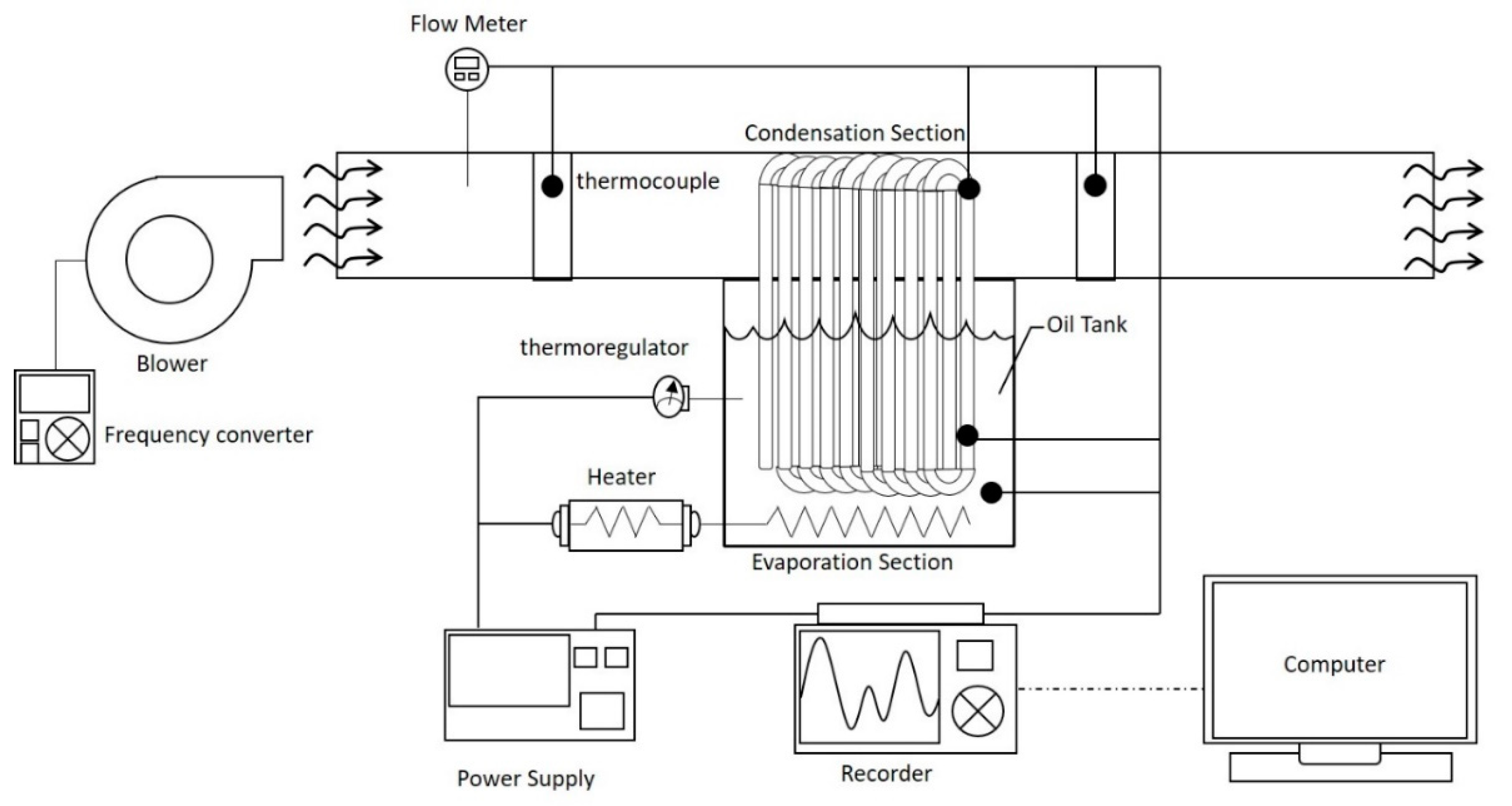
Figure 2.
(a) The detailed configuration of the present HPHX. (b) An actual example (unit: mm).

Figure 3.
(a) Thermocouples’ positions on the tube on evaporator and condenser sides; (b) thermocouple positions at the inlet and outlet of the cooling air duct.
Figure 3.
(a) Thermocouples’ positions on the tube on evaporator and condenser sides; (b) thermocouple positions at the inlet and outlet of the cooling air duct.
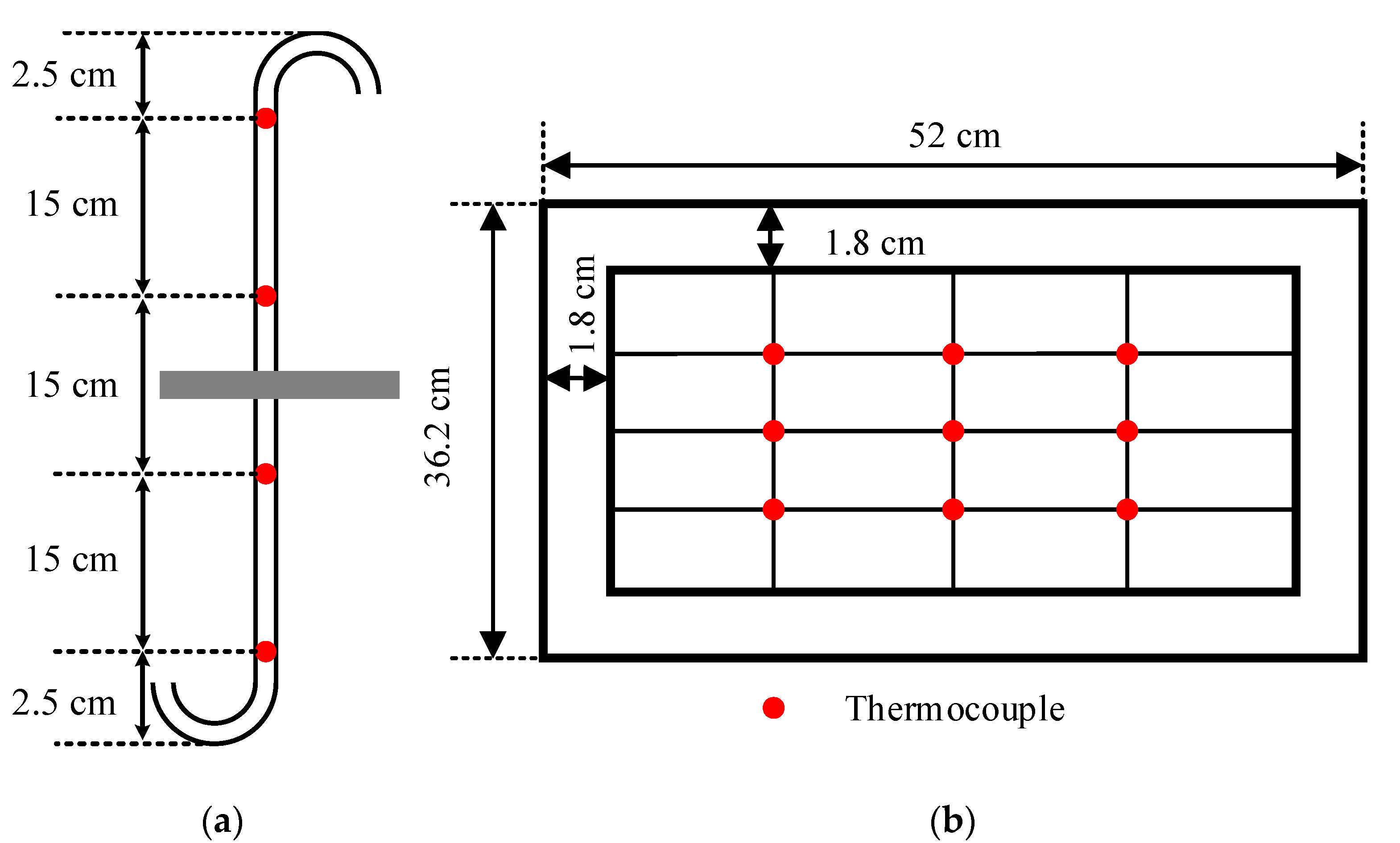
Figure 4.
The histories of evaporator and condenser temperatures with increasing heating pool temperature under a cooling air flow rate of 400 CMH.
Figure 4.
The histories of evaporator and condenser temperatures with increasing heating pool temperature under a cooling air flow rate of 400 CMH.

Figure 5.
Comparison of experimental and theoretical temperatures of the evaporator and the condenser, and the average cooling air temperatures, under (a) 400 CMH, (b) 800 CMH, (c) 1200 CMH and (d) 1600 CMH.
Figure 5.
Comparison of experimental and theoretical temperatures of the evaporator and the condenser, and the average cooling air temperatures, under (a) 400 CMH, (b) 800 CMH, (c) 1200 CMH and (d) 1600 CMH.
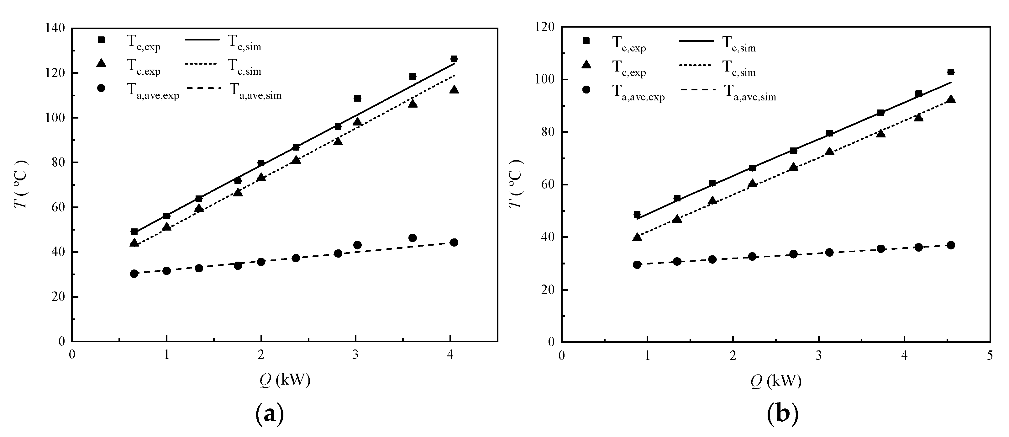

Figure 6.
Decomposed theoretical thermal resistances along with the experimental total resistances under (a) 400CMH, (b) 800 CMH, (c) 1200 CMH and (d) 1600 CMH.
Figure 6.
Decomposed theoretical thermal resistances along with the experimental total resistances under (a) 400CMH, (b) 800 CMH, (c) 1200 CMH and (d) 1600 CMH.
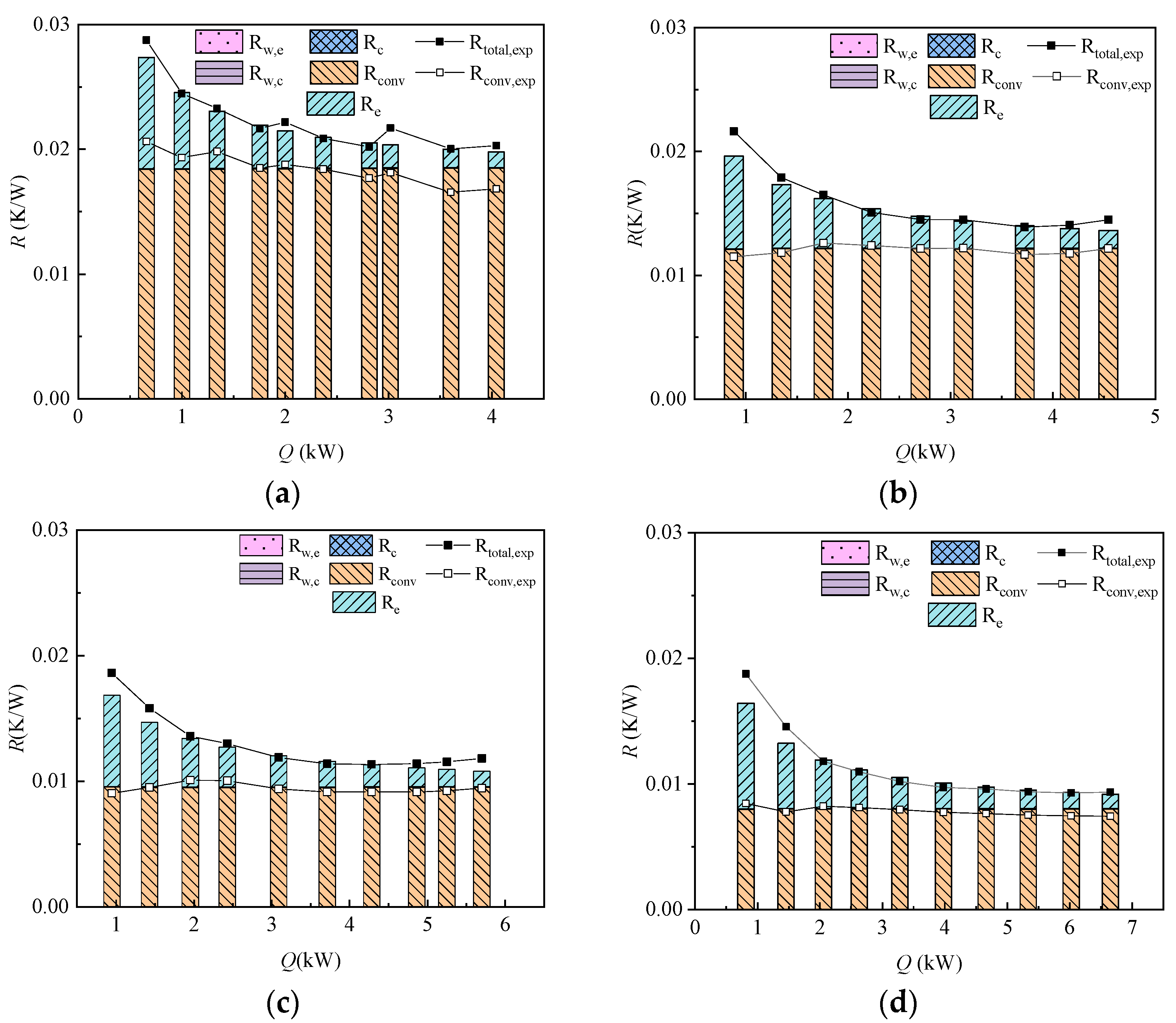
Figure 7.
Decomposed theoretical thermal resistances and heat transfer coefficients under 400 CMH.
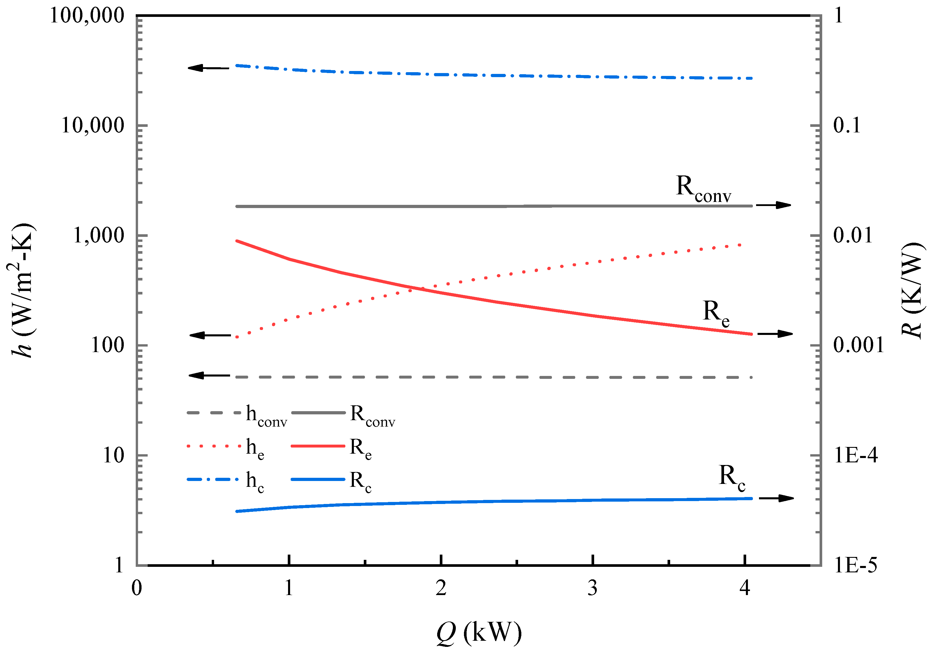
Figure 8.
A comparison of experimental and theoretical total resistances under various cooling air flow rates.
Figure 8.
A comparison of experimental and theoretical total resistances under various cooling air flow rates.

Table 2.
Test conditions.
| Working Fluid/ Filling Ratio | Nominal Cooling Air Flow Rate (CMH) | Nominal Heating Pool Temperature Th (°C) |
|---|---|---|
| Water/40% | 400 | 60–160 |
| 800 | ||
| 1200 | 60–150 | |
| 1600 |
Table 3.
Geometric parameters of the HPHX.
| evaporator length, Le | 235 mm |
| condenser length, Lc | 235 mm |
| tube OD | 9.5 mm |
| tube ID | 8.3 mm |
| longitudinal pitch of the tube bank, SL | 22.0 mm |
| transverse pitch of the tube bank, ST | 25.4 mm |
| row number of the tube bank, n | 9 |
| total tube number | 153 |
| cross-sectional area of the cooling air duct | 0.11 m2 |
Publisher’s Note: MDPI stays neutral with regard to jurisdictional claims in published maps and institutional affiliations. |
© 2021 by the authors. Licensee MDPI, Basel, Switzerland. This article is an open access article distributed under the terms and conditions of the Creative Commons Attribution (CC BY) license (https://creativecommons.org/licenses/by/4.0/).
Share and Cite
MDPI and ACS Style
Yang, K.-S.; Wu, Y.-L.; Chu, Y.-P.; Wu, Y.-L.; Wong, S.-C. Performance Tests on a Novel Un-Finned Thermosyphon Heat Exchanger Requiring a Single Charge. Processes 2021, 9, 995. https://doi.org/10.3390/pr9060995
AMA Style
Yang K-S, Wu Y-L, Chu Y-P, Wu Y-L, Wong S-C. Performance Tests on a Novel Un-Finned Thermosyphon Heat Exchanger Requiring a Single Charge. Processes. 2021; 9(6):995. https://doi.org/10.3390/pr9060995
Chicago/Turabian StyleYang, Kai-Shing, Yan-Lin Wu, Yi-Pin Chu, Yu-Lieh Wu, and Shwin-Chung Wong. 2021. "Performance Tests on a Novel Un-Finned Thermosyphon Heat Exchanger Requiring a Single Charge" Processes 9, no. 6: 995. https://doi.org/10.3390/pr9060995
Note that from the first issue of 2016, this journal uses article numbers instead of page numbers. See further details here.