Mechanism of the Breakage of Spherical Gypsum Particles under 3-Point Contact Conditions


1
Department of Geotechnical Engineering, Tongji University, Shanghai 200092, China
2
CSC Dongfu Assets Management Co., Ltd., Shanghai 200135, China
*
Author to whom correspondence should be addressed.
Processes 2021, 9(6), 1029; https://doi.org/10.3390/pr9061029
Submission received: 8 May 2021
/
Revised: 7 June 2021
/
Accepted: 9 June 2021
/
Published: 11 June 2021
Abstract
:Particle breakage has a great influence on the mechanical properties of coarse-grained soil materials. In the structure, a particle usually contacts with several surrounding particles when breakage occurs. The crushing mechanism of spherical particles under three-point contact conditions was investigated theoretically and experimentally. In the theoretical analysis, the contact force required for particle breakage is solved by using a stress superposition method based on the ball–ball contact model. To verify the theory, particle contact tests of gypsum spheres under three-point contact conditions were carried out. The experimental results are consistent with the theoretical prediction. Different from the ball–ball contact test, the rupture surface after breakage is a fixed plane passing through all three contact points under three-point contact conditions. Under multi-point contact conditions, the size of the conical core depends on the normal force on the contact point at the moment of particle breakage. Multi-point contact makes particle breakage more difficult, and the stronger the constraint of surrounding spheres, the more difficult it is for the particle to break. Both the theory and the experiment provide evidence that the arrangement of particles affects the overall strength of the coarse-grained soil structure.
1. Introduction
Coarse-grained soils have good compaction performance, strong permeability, high filling density, high shear strength, low settlement deformation, and high bearing capacity. They are abundant in nature and are used extensively in earth rock dams, highways, railways, airports, dams, bridge piers, artificial islands, and ground treatment engineering applications [1]. Early research on coarse-grained materials was generally conducted along the lines of studies of sandy soils or normally consolidated clays [2,3,4,5]. Different from these kinds of soils, the particles in the coarse-grained soil may crush under the condition of high stress. In recent years, the problem of particle breakage in high-fill engineering projects, which directly affects the reliability of the overall structure, has attracted the attention of a growing number of academics [6,7,8,9,10,11,12,13].
Common methods used to study the breakage of coarse-grained soil particles include the shear test [14,15,16,17,18,19], the triaxial test [20,21,22,23,24], the uniaxial compression test [5,25,26], and the particle contact test [1,27,28,29,30]. The particle contact test proposed by Zhou [28] is a method to investigate the micromechanism of the breakage of a single particle, which has been increasingly adopted by scholars [1,27,31,32] since the research on the macro mechanical properties of coarse-grained soils has hit a bottleneck. In the particle contact test, many factors affect the microscope characteristics of breakage, such as the shape [1], size [33], and material [30] of the particles; the form of contact (ball–plane [29,32] and ball–ball [27,34]); and the state of forces [35,36]. However, although there are already many experimental studies on various influencing factors, the mechanism of the breakage of a single particle has not been studied comprehensively.
The complexity of particle shape brings uncertainty to the study on the micromechanism of particle breakage, and the current research on it is not mature. Therefore, studying the crushing characteristics of spherical particles is a common and effective method to reveal the mechanical properties during the breakage process. Among the studies on spherical particles, the conical core (see Figure 1) was discovered and valued by Zhou et al. [29] through investigating the fragmentation properties of spherical marble particles under ball–plane contact conditions. Yu et al. [32] observed the development process of internal fractures during the breakage of spherical particles and revealed the formation mechanism of the conical core combining experiments and numerical simulations.
Most of the research on contact fracture of spherical rock materials is based on Hertz model, such as Mindlin and Deresiewicz [37], Hiramatsu and Oka [38], and Chau et al. [39]. This classical model assumes that the object of study is an elastomer during the whole contact process and can solve the stress state distribution inside the spherical particle very accurately. However, this model is unable to analyze the formation process and mechanism of the conical core. Therefore, to further reveal the mechanical characteristics of spherical particles during their crushing and the formation mechanism of the conical core, Niu et al. [34] explored the micromechanism of spherical particles breaking under the condition of ball–ball contact by employing theoretical analyses and tests, dividing the crushing process into three stages—local compaction stage, elastic deformation stage, and integral crushing stage (see Figure 1). In the above studies, the spherical particle only contacts with a flat plate or another sphere. Nevertheless, in the soil structure, a single particle usually contacts with several surrounding particles together, so there are multiple contact points, which has a non-negligible effect that remains unclear on the crushing mechanism of the particles. As a result, it is essential to study the particle breakage mechanism under multi-point contact conditions. Riccardo et al. [40] studied the influence of contact location on the crushing characteristics of cylindrical particles under multiple contact areas conditions through experiments and numerical simulations. However, the fracture characteristics of spherical particles under multi-point contact conditions may be different.
The number of contact points affects the particle breakage morphology and overall strength, but does not change the mechanical mechanism. Therefore, in this paper, the mechanism of the breakage of the spherical particle under the simple three-point contact condition is discussed theoretically and experimentally to reveal the micromechanism of the breakage of particles under multi-point contact conditions. Based on the contact model under ball–ball normal contact conditions proposed by Niu et al. [34], the stress state inside the spherical particle is solved and the response of the contact force when breakage occurs is reproduced under three-point contact conditions. The particle contact tests of high-strength gypsum spheres under three-point contact conditions were performed to verify the theoretical analysis. The theoretical research and experimental results in this paper are in good agreement. Furthermore, the results of the particle contact test under three-point contact conditions are compared with those under ball–ball normal contact conditions to understand the influence of the presence of multiple contact points on the law of particle breakage. It is found that multi-point contact increases the difficulty of particle breakage and that the breaking morphology is related to the location of contact points.
2. Theoretical Analysis
In actual conditions, the force state of a single particle in the coarse-grained soil structure is complex. This paper adopted the hypothesis that the breakage of spherical particles under multi-point contact conditions is caused by the contact point with the greatest contact force [33]. Consequently, it is of great significance to only study the stress state near the contact point where the force is greatest, and this paper studies the specific three-point contact situation shown in Figure 2 to facilitate the analysis. Particle I is the object to analyze and from the diagram, the following equation is obtained:
F is the contact force between Particles I and II. F′ is the contact force between Particles I and III/IV. The stress state in Particle I and its fracture mechanism are discussed in detail in the following sections.
2.1. Model for Ball–Ball Normal Contact
The micromechanism of the breakage of two spherical particles under ball–ball normal contact conditions (see Figure 3b) has been investigated and a new contact model considering the formation of the conical core has been proposed by Niu et al. [34]. Before analyzing the crushing mechanism under three-point contact conditions, it is necessary to give a brief overview of this contact model.
The whole process of the breakage of spherical particles is divided into three stages—local compaction, elastic deformation, and integral crushing. In the local compaction stage, a flat circular region is formed due to stress concentration under the contact point, which is also the bottom of the conical core. In the elastic deformation stage, the area of the circular region is no longer enlarged, and the stress state along the diameter of the sphere, which is perpendicular to the bottom surface of the conical core and passes through its center, is as follows:
σρ, σφ and σz are defined in Figure 3c. Fn is the normal force at the contact point, a is the radius of the bottom of the conical core, and ν is Poisson’s ratio of the material. Then, a simple two-parameter multiaxial failure criterion for brittle materials proposed by Christensen [41,42] is applied to obtain the normal force at the contact point when the integral crushing occurs. The criterion simplified by Russell and Muir [43] states that material is at failure when we have the following:
Κmob is a parameter used to describe the stress state of a point in the material and its value can be obtained through the following equation:
σii is the first invariant of the stress tensor, and sijsij is the second invariant of the deviatoric stress tensor. The parameter ψ and Κ are defined as follows:
σt and σc are the uniaxial tensile strength and uniaxial compressive strength of the material, respectively. Combining Equations (2), (3) and (5), the plot of Κmob in the sphere along the line normal to and through the center of the base of the conical core is presented in Figure 3a. When Κmob at a point on the central axis of the sphere passing through the center of the bottom surface of the conical core reaches Κ, the whole sphere crushes, and the normal force Fcr when integral crushing occurs can be obtained by combining Equations (2)–(7). This point is also the apex of the conical core.
2.2. Solutions under Three-Point Contact Conditions
From Figure 2, if θ < 30°, geometric relationships cannot be satisfied. On the other hand, if θ > 90°, the force balance condition cannot be met. As a result, θ varies between 30° and 90°. Furthermore, when 30° ≤ θ < 60°, F′ < F, and the integral crushing is caused by the contact point between Particles I and II. When θ ≥ 60°, F′ ≥ F, and the integral crushing is caused by the contact point between Particles I and III/IV. In both cases, only the position where the breakage begins is different, while the micromechanism of particle breakage is similar. Therefore, in this paper, the contact point between Particles I and II is selected as the research object, and only the theoretical derivation for the first case (30° ≤ θ < 60°) is made.
According to the contact model under ball–ball normal contact conditions [34], the contact process between Particles I and II includes three stages—local compaction, elastic deformation, and integral crushing. The authors make the reasonable assumption that the extrusion of Particles III and IV does not affect the hardness modulus of the contact point portion between Particles I and II. For this reason, the process of the local compaction stage at this point is identical to that under ball–ball normal contact conditions. Meanwhile, the size of the conical core is much smaller than the distance of the three contact points, which means that the contact point between Particles I and III/IV can be assumed to have the same degree of influence on the stress state at each point near the contact point between Particles I and II. Hence, the conical core formed at the contact point between Particles I and II is of the same size as that under ball–ball normal contact conditions and the size can be obtained as follows:
As shown in Figure 4a, the corresponding cylindrical coordinate systems are established for different contact points, separately. Assuming that Point M is the vertex of the conical core, the stress components of this point caused by Particle II shown in Figure 4b can be obtained by Equations (2) and (3). To obtain the true stress state at Point M, the stress components at point M caused by Particles III and IV need to be calculated, respectively.
According to the symmetry, only the analysis of the contact point between Particles I and III is presented here. For the contact point between Particles I and III, local compaction also occurs when the compression is applied, forming a circular plane region. However, Point M is far from this contact point. As a result, when calculating the stress components of it caused by Particle III shown in Figure 4c, the boundary condition is equivalent to the point load F′ acting on the contact point and pointing to the center of Particle I due to the Saint-Venant principle. In the present study, solutions for the stresses within the half-space subjected to a concentrated force, P, (see Figure 5) are of interest, and the stress state at any point is shown as follows [44]:
Since the size of the conical core is much smaller than that of the whole sphere, Point M can be regarded as the contact point between Particles I and II in the calculation. By separately substituting P = F′, z = 2Rcos2θ′, ρ = 2Rsinθ′cosθ′ and r = 2Rcosθ′ into Equations (10)–(13), the stress state at Point M caused by Particle III shown in Figure 4c is obtained:
According to the above analysis, θ′ ≈ θ/2, and the true stress state of Point M can be obtained by superimposing the stress components generated by the three contact points separately. The results are as follows:
Substituting Equations (18)–(20) into Equations (4)–(7), the contact force Fcr exerted by Particle II for Particle I crushing can be obtained. As shown in Figure 1, the larger the value of θ, the greater the contact force, , between Particles I and III/IV when breakage occurs. Figure 6 plots the relationship between Fcr and of different materials under the condition of 30° ≤ θ < 60°, in which the contact force between Particles I and II at failure increases with the increasing . Therefore, the more lateral restraint a particle is subjected to, the more difficult it is to break. For the limestone material, the normal force between Particles I and III/IV varies from 8.72 to 15.54 kN for the values of θ that vary from 30° to 60°, while the contact force between Particles I and II varies from 15.11 to 15.54 kN. Moreover, the normal force at failure under ball–ball contact conditions is 13.89 kN when using Niu et al.’s model [34]. This indicates that the difficulty of particle breakage increases with the increasing contact points number, as well as the increasing constraints from surrounding particles, and that the change in the number of contact points has a greater effect on the difficulty of particle breakage than the change in the magnitude of the lateral binding force.
3. Particle Contact Test under Three-Point Contact Conditions
In this subsection, we discuss the particle contact tests under three-point contact conditions that were carried out with θ varying from 30° to 90°. The experimental results are compared with the theoretical prediction and the details are discussed below.
3.1. Materials and Methods
The high-strength gypsum spheres were used to simulate the coarse-grained soil particles in this study, which is made by the Sanxin dental plaster produced by Yuyao Xinshi Gypsum Products Co., Ltd., Yuyao, Zhejiang, China. The reason for selecting gypsum material is that the sample preparation is simple and the sample texture is uniform to simulate isotropic brittle materials. For 25% water content (defined as the mass of water divided by the mass of dental stone powder), the 1-h and long-term compressive strengths of the gypsum made by the dental stone powder are approximately 35 and 75 MPa, respectively. In this experiment, the gypsum was made by using water contents of 35% during the mixing, and the mixing time and curing time were 5 min and 14 days, respectively. Spheres with a diameter of about 50 mm were prepared with the rubber mold. The reason for choosing this particle size is that if the particle size is too large, the exothermic hardening process of gypsum may induce temperature cracking inside the specimen and that too small particles make it difficult to monitor and observe the crushing process. The basic mechanical parameters acquired by rock tests for the high-strength gypsum material used in this test are shown in Table 1. Among these mechanical parameters, Young’s modulus, Poisson ratio, and unconfined compressive strength were obtained by compressing solid circular cylinders of the materials with length 100 mm and diameter 50 mm, while tensile strength was obtained by the Brazilian splitting test of solid circular cylinders of the materials with length 50 mm and diameter 50 mm. To measure the crushing modulus of the gypsum spheres, particle contact tests under ball–plane contact conditions were performed, in which the loading was stopped when the pressure reached only 800 N, and the work done by the pressure and the final compaction volume were recorded during the loading. All of the results are the means of 5 repeated tests.
All the tests were conducted by using a rock rheological testing system (see Figure 7a) which can provide a maximum vertical force of 500 kN and a horizontal force of 300 kN. The system is equipped with a high-speed static force–displacement acquisition system, and the highest acquisition frequency is 100 times per second. In this experiment, the acquisition frequency was set to 5 times per second.
In the test, particles were fixed with a self-developed fixture shown in Figure 7b. This fixture can adjust the distance between Particles III and IV by changing the position of the baffles on both sides to change the value of θ. Since the research object of this study is Particle I, to prevent Particles II–IV from crushing during the test, the adjustable restraint bearing is used to fix Particle II, while Particles III and IV are fixed by arc-shaped supports. The distance between two lateral baffles and the size of the adjustable restraint bearing can be changed by adjusting the screws and nuts. Before the tests started, each sphere was lubricated with oil to eliminate friction effects.
During the test, the vertical loading component slowly applied pressure to the adjustable restraint bearing until Particle I was crushed, and the contact forces on the three contact points were separately recorded by the force–displacement sensor shown in Figure 7a and the force sensors shown in Figure 7b. After the crushing of Particle I, the size of the conical core at each contact point, the breakage form, and the contact force at the moment of breaking were recorded. There were 6 groups in the test, with each corresponding to a θ of 30°, 40°, 50°, 60°, 70° and 80°, and the distances between Particles III and IV were 0, 13.7, 25.5, 35.1, 42.2, and 46.5 mm. Each test group was repeated 3 times.
3.2. Results
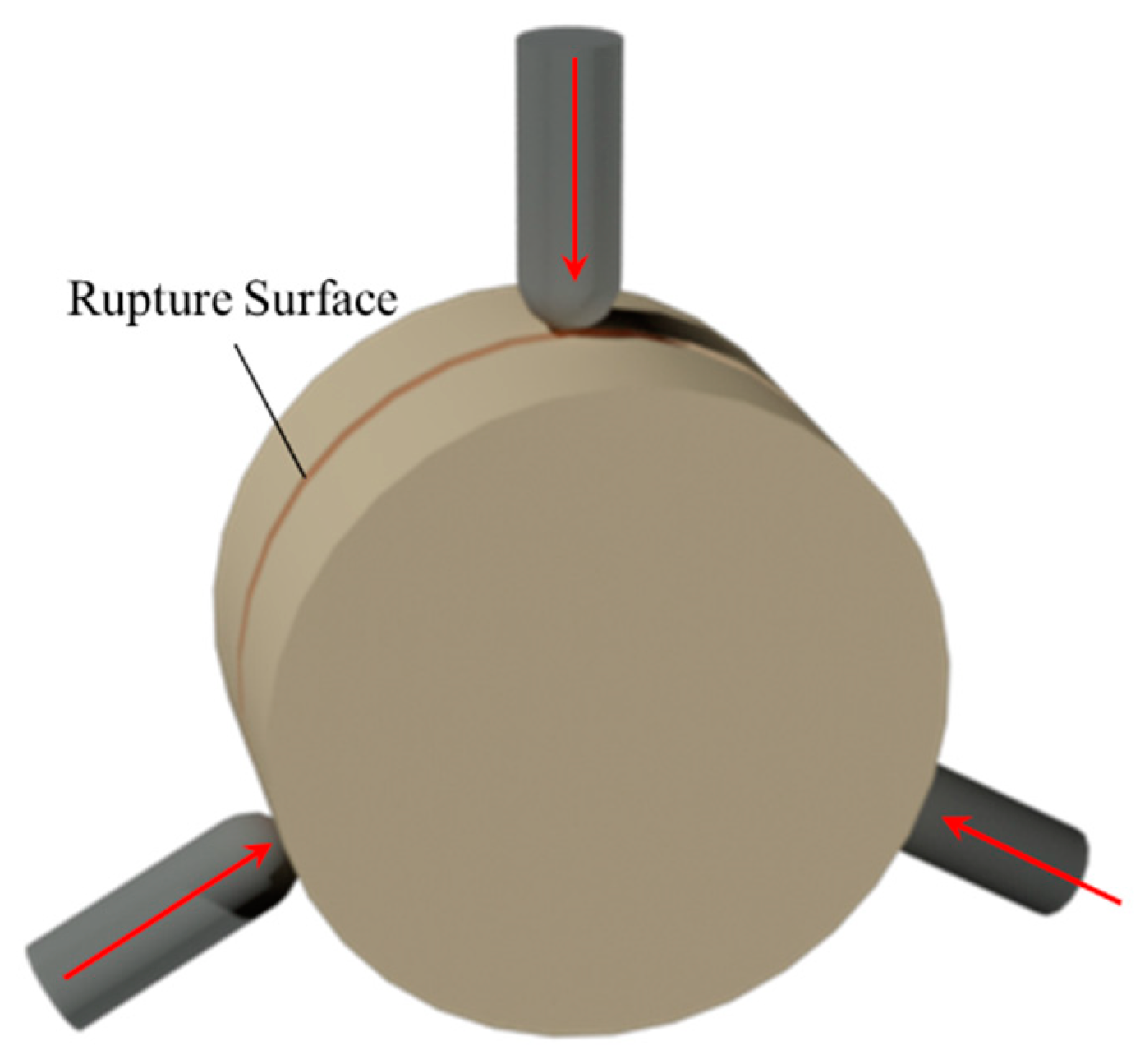
In the test, Particle I broke into two symmetrical hemispheres, and the rupture surface was a plane passing through the three contact points (see Figure 8). Furthermore, a conical core was formed at each contact point due to the local compaction. In particle contact tests under ball–plane [32] and ball–ball [34] contact conditions, the rupture surface is any plane passing through the contact point and the center of the sphere. However, under three-point contact conditions, the rupture surface is a fixed plane that passes through the sphere center and the three contact points. The reasons for this difference are as follows: concerning particle contact tests with only one contact point, the conical core vertex is in the stress state where σρ = σφ when breakage occurs, according to Equation (3); in the tests under three-point contact conditions, the presence of contact points between Particles I and III/IV causes the vertex of the conical core produced by Particle II to be in the stress state where σρ < σφ when breakage occurs according to Equations (18) and (19).
Figure 9 shows the results of the dimensions of conical cores measured in the tests. There are three contact points between Particle I and the surrounding particles, and three conical cores are formed after breakage. From the figure, it is found that the sizes of the conical cores do not differ significantly for both different values of θ and contact point positions. The reasons are analyzed as follows. According to the contact model proposed by Niu et al. [34], the critical normal force Fnc between the local compaction stage and the elastic deformation stage during contact breakage of two spherical particles can be obtained by the following equations:
where α is a parameter determined by Young’s modulus, the hardness modulus, and Poisson’s ratio of the material. For this test, Fnc takes the value of 1.518 kN, which is much smaller than the maximum normal force at each contact point during the experiment. Accordingly, when breakage occurs, all the contact points have ended the local compaction phase and the conical core size has reached the maximum possible value, which is the reason why all conical cores in this test have the same dimension with a weak dependence on θ and the position of the contact point.
Before the formal tests, the authors made theoretical predictions of the minimum contact force between Particles I and II required for the breakage, which are presented as follows:
When 30° ≤ θ ≤ 60°, the value of Fcr is obtained by combining Equations (4)–(7) and (12)–(14). Meanwhile, is the contact force between Particles I and II/III/IV when the breakage occurs under the condition of θ = 60°.
When θ > 60°, F′ > F and it is Particle III or IV, rather than II, that causes Particle I to crush. The author makes the following reasonable assumption: the contact force between Particles I and III/IV required for the breakage of Particle I is always , since the change of the binding force of surrounding particles has little effect on the contact force required for particle breakage (see Figure 6). Therefore, in this case, the contact force between Particles I and II when breakage occurs is shown below:
The values of the contact force between Particles I and II when breakage occurs are plotted in Figure 10, with the theoretical relationship between Fcr and θ plotted for comparison. The experimental data are in good agreement with the theoretical prediction. When 30° ≤ θ < 60°, the contact force between Particles I and II at failure increases slightly with the increasing lateral restraint. When θ ≥ 60°, the contact force between Particles I and II at failure decreases with the increasing lateral restraint, and the reason is that, at the moment of breaking, the crack originated at the contact point between Particles I and III/IV rather than the contact point between Particles I and II.
4. Discussion
In this study, to investigate the influence of multi-point contact on the braking mechanism of spherical particles, the breakage of brittle spheres under three-point contact conditions was discussed theoretically and experimentally. Based on the particle contact model proposed by Niu et al. [34], the breakage of spherical particles under multi-point contact conditions was solved by the stress superposition method. The effect of multi-point contact on particle breakage is discussed in detail in this section.
Multi-point contact affects the crushing morphology of spherical particles. In the particle contact test under ball–ball contact conditions, the rupture surface is any plane passing through the conical core vertex and the sphere center due to the symmetric stress state in the sphere. When there are multiple contact points, the stress state inside the particle changes asymmetrically, resulting in the certainty of the fracture surface. For example, in particle breakage tests under three-point contact conditions, the final rupture surface is a fixed plane passing through all the contact points. However, there are two rupture surfaces perpendicular to the bottom surface (see Figure 11) when a cylindrical particle breaks under three contact conditions [40], which is different from the crushing patterns of spherical particles (see Figure 8). The reason for the difference is that the load on the particle surface is close to the point load in the multiple spherical particles contact test, while the load on the particle surface is line load in the multiple cylindrical particles contact test. According to the theoretical analysis of this paper, if a cylindrical particle is loaded at three points, as shown in Figure 12, the rupture surface will be parallel to the bottom surface and pass through the three contact points when the breakage occurs, and the particle will break into two identical cylinders. This provides evidence that different contact forms lead to different fracture forms.
In engineering structures, broken particles still provide bearing capacity for the soil. Therefore, the breakage form of particles after crushing affects the overall strength of the soil structure. In coarse-grained soil structures, the arrangement of particles affects the number and location of contact points between a single particle and the surrounding particles of it, thus affecting the particle breakage form. As a result, the present study provides evidence for the viewpoint that the arrangement of coarse-grained soil particles has an impact on the soil strength, considering particle breakage. In this paper, only the particle breakage morphology under special conditions of three-point contact was discussed, and it has certain limitations. In further research, the effect of the particle arrangement on particle breakage morphology and soil strength needs to be studied in detail.
There are no significant differences in the dimensions of the conical cores measured in the tests, and the reason is that, when the sphere crushes, all contact points end the local compression phase and enter the elastic deformation phase shown in Figure 1, in which the size of the conical core hardly continues to get bigger. However, under multi-point contact conditions, when the particle breakage occurs, there may be contact points where the contact force is not large enough, so that they are still in the local compaction stage. This situation is not discussed in this paper and needs to be further studied in future works.
The contact force required for the particle breaking under three-point contact conditions is theoretically predicted in the present study, and the data measured in the test are in good agreement with the theoretical prediction. Compared with the particle breakage under ball–ball contact conditions [34], multi-point contact increases the difficulty of the breakage of a single particle, and the greater the binding forces of the surrounding particles, the more difficult it is to crush. If the contact force for the particle breakage under ball–ball contact conditions is , according to the theoretical analysis, the contact force between Particles I and II required for Particle I crushing varies between and when 30° ≤ θ ≤ 60° in this paper. Therefore, the number of contact points has a greater influence on the difficulty of particle breakage than the binding forces of the surrounding particles, meaning that increasing the number of particle contact points in soil reduces the breakage rate more effectively. This conclusion is consistent with Niu et al.’s [33].
In this paper, the stress superposition method was used in the analysis of particle breakage under three-point contact conditions, which provides a research idea for studying multi-point contact breakage. In the theoretical analysis, the authors assume that there is only a normal force at each contact point, while, in reality, there are both normal and tangential forces, although the tangential force is very small compared to the normal force. In further research, the co-existence of normal and tangential forces under multi-point contact conditions needs to be discussed.
5. Conclusions
In the present study, the breakage mechanism of brittle spherical particles under three-point normal contact conditions was discussed theoretically and experimentally. In the theoretical analysis, the contact force required for particle breakage was solved by using a stress superposition method based on the ball–ball contact model. To verify the validity of the theoretical analysis, particle contact tests under three-point contact conditions were carried out. The main conclusions are as follows:
- Under three-point contact conditions, the fracture surface is a plane passing through the three contact points, which is different from the breakage form in the ball–ball normal contact test.
- Under multi-point contact conditions, the form of contact has a significant effect on the fracture morphology of particles.
- Under multi-point contact conditions, a conical core is formed under each contact point, and the size of the conical core depends on the magnitude of the normal force on the contact point at the moment of particle breakage.
- Multi-point contact effectively increases the difficulty of particle breakage. The stronger the constraint of the surrounding particles, the more difficult it is for the particle to break.
- The arrangement of particles in a coarse-grained soil structure affects the number and location of contact points between particles and their surrounding particles, thus affecting the difficulty of particle breakage and the breakage form. Therefore, the arrangement of particles affects the overall strength of the structure.
6. Patents
The self-developed fixture used in the particle contact test was authorized by the State Intellectual Property Office of China. Name of invention: A multi-point contact test device for spherical particles and its loading method. Patent number: ZL201910594596.5.
Author Contributions
Conceptualization, Y.N.; formal analysis, Y.N.; resources, L.L. and S.Y.; data curation, L.L. and Y.Z.; writing—original draft preparation, Y.N.; writing—review and editing, Y.N. All authors have read and agreed to the published version of the manuscript.
Funding
This research was funded by the National Natural Science Foundation of China (No. 51479138).
Institutional Review Board Statement
Not applicable.
Informed Consent Statement
Not applicable.
Data Availability Statement
The data presented in this study are available in the insert article.
Conflicts of Interest
The authors declare no conflict of interest. The funders had no role in the design of the study; in the collection, analyses or interpretation of data; in the writing of the manuscript; or in the decision to publish the results.
References
- Zhao, C.; Hou, R.; Zhou, J. Particle Contact Characteristics of Coarse-Grained Soils under Normal Contact. Eur. J. Environ. Civ. Eng. 2018, 22, s114–s129. [Google Scholar] [CrossRef]
- Dayakar, P.; Raju, K.V.B.; Sankaran, S. Improvement of Coarse Grained Soil by Permeation Grouting Using Cement Based HPMC Grout. Int. J. Emerg. Technol. Adv. Eng. 2014, 4, 17–22. [Google Scholar]
- Nakata, T.; Miura, S. Change in void structure due to particle breakage of volcanic coarse grained soil and its evaluation. Doboku Gakkai Ronbunshuu 2007, 63, 224–236. [Google Scholar] [CrossRef]
- Nguyen, B.T.; Ishikawa, T.; Murakami, T. Effects evaluation of grass age on hydraulic properties of coarse-grained soil. Transp. Geotechnics 2020, 25, 100401. [Google Scholar] [CrossRef]
- Indrawan, I.G.B.; Rahardjo, H.; Leong, E.C. Effects of coarse-grained materials on properties of residual soil. Eng. Geol. 2006, 82, 154–164. [Google Scholar] [CrossRef]
- Åström, J.A.; Herrmann, H.J. Fragmentation of Grains in a Two-Dimensional Packing. Eur. Phys. J. B 1998, 5, 551–554. [Google Scholar] [CrossRef]
- Ben-Nun, O.; Einav, I. The Role of Self-Organization during Confined Comminution of Granular Materials. Philos. Trans. A Math. Phys. Eng. Sci. 2010, 368, 231–247. [Google Scholar] [CrossRef] [PubMed] [Green Version]
- Cavarretta, I.; Coop, M.; O’Sullivan, C. The Influence of Particle Characteristics on the Behaviour of Coarse Grained Soils. Geotechnique 2010, 60, 413–423. [Google Scholar] [CrossRef] [Green Version]
- Coop, M.R.; Sorensen, K.K.; Freitas, T.B.; Georgoutsos, G. Particle Breakage during Shearing of a Carbonate Sand. Geotechnique 2004, 54, 157–163. [Google Scholar] [CrossRef]
- Delenne, J.Y.; Youssoufi, M.S.E.; Cherblanc, F.; Bénet, J.C. Mechanical Behaviour and Failure of Cohesive Granular Materials. Int. J. Numer. Anal. Met. 2004, 28, 1577–1594. [Google Scholar] [CrossRef]
- Subero, J.; Ghadiri, M. Breakage Patterns of Agglomerates. Powder Technol. 2001, 120, 232–243. [Google Scholar] [CrossRef]
- Qiu, Z.; Cao, T.; Li, Y.; Wang, J.; Chen, Y. Rheological Behavior and Modeling of a Crushed Sandstone-Mudstone Particle Mixture. Processes 2018, 6, 192. [Google Scholar] [CrossRef] [Green Version]
- Li, J.; Huang, Y.; Qiao, M.; Chen, Z.; Song, T.; Kong, G.; Gao, H.; Guo, L. Effects of Water Soaked Height on the Deformation and Crushing Characteristics of Loose Gangue Backfill Material in Solid Backfill Coal Mining. Processes 2018, 6, 64. [Google Scholar] [CrossRef] [Green Version]
- Fu, P.C.; Dafalias, Y.F. Fabric Evolution within Shear Bands of Granular Materials and Its Relation to Critical State Theory. Int. J. Numer. Anal. Met. 2011, 35, 1918–1948. [Google Scholar] [CrossRef]
- Kim, D.; Ha, S. Effects of Particle Size on the Shear Behavior of Coarse Grained Soils Reinforced with Geogrid. Materials 2014, 7, 963–979. [Google Scholar] [CrossRef] [PubMed] [Green Version]
- Li, Y. Test Granular Materials Failure Using Bi-Directional Simple Shear Apparatus: A Review. Appl. Sci. 2018, 8, 1140. [Google Scholar] [CrossRef] [Green Version]
- Lin, P.S.; Chang, C.W.; Chang, W.J. Characterization of Liquefaction Resistance in Gravelly Soil: Large Hammer Penetration Test and Shear Wave Velocity Approach. Soil Dyn. Earthq. Eng. 2004, 24, 675–687. [Google Scholar] [CrossRef]
- Tejchman, J.; Górski, J.; Einav, I. Effect of Grain Crushing on Shear Localization in Granular Bodies during Plane Strain Compression. Int. J. Numer. Anal. Met. 2012, 36, 1909–1931. [Google Scholar] [CrossRef]
- Wang, J.; Yan, H. On the Role of Particle Breakage in the Shear Failure Behavior of Granular Soils by Dem. Int. J. Numer. Anal. Met. 2013, 37, 832–854. [Google Scholar] [CrossRef]
- Anhdan, L.Q.; Tatsuoka, F.; Koseki, J. Viscous Effects on the Stress-Strain Behavior of Gravelly Soil in Drained Triaxial Compression. Geotech. Test. J. 2006, 29, 660–661. [Google Scholar] [CrossRef]
- Kongsukprasert, L.; Tatsuoka, F. Ageing and Viscous Effects on the Deformation and Strength Characteristics of Cement-Mixed Gravelly Soil in Triaxial Compression. Soils Found. 2005, 45, 55–74. [Google Scholar] [CrossRef] [Green Version]
- Lee, K.L.; Farhoomand, I. Compressibility and Crushing of Granular Soil in Anisotropic Triaxial Compression. Can. Geotech. J. 1967, 4, 68–86. [Google Scholar] [CrossRef]
- Maqbool, S.; Koseki, J. Large-Scale Triaxial Tests to Study Effects of Compaction Energy and Large Cyclic Loading History on Shear Behavior of Gravel. Soils Found. 2010, 50, 633–644. [Google Scholar] [CrossRef] [Green Version]
- McDowell, G.R.; Li, H. Discrete Element Modelling of Scaled Railway Ballast under Triaxial Conditions. Granul. Matter 2016, 18, 66. [Google Scholar] [CrossRef] [Green Version]
- Hardin, B.O. Crushing of Soil Particles. J. Geotech. Eng. 1985, 111, 1177–1192. [Google Scholar] [CrossRef]
- Nakata, Y.; Kato, Y.; Hyodo, M.; Hyde, A.F.; Murata, H. One-Dimensional Compression Behaviour of Uniformly Graded Sand Related to Single Particle Crushing Strength. Soils Found. 2001, 41, 39–51. [Google Scholar] [CrossRef] [Green Version]
- Li, L.; Zhao, C.; Zhang, Y.W.; Ouyang, G.B.; Yu, S.C.; Zhou, J. Particle Breakage Characteristics of Coarse-Grained Soil under Point-Point Contact. In IOP Conference Series: Earth and Environmental Science; IOP Publishing: Beijing, China, 2020. [Google Scholar] [CrossRef]
- Zhou, J. Experimental Study on Contact of Gypsum Particles. Chin. J. Tongji Univ. 2016, 44, 67–72. [Google Scholar] [CrossRef]
- Zhou, J.; Niu, Y.R.; Zhou, Y.H.; Zhang, J.; Zhao, C. The Ball-Surface Normal Contact Experiment Research and Numerical Simulation of Coarse Grained Soil. In Proceedings of the GeoShanghai 2018 International Conference: Fundamentals of Soil Behaviours; Springer: Singapore, 2018. [Google Scholar] [CrossRef]
- Zhou, J.; Zhang, Y.W.; Zhou, Y.; Zhang, J. Experimental Study on Particle Breakage of Coarse-Grained Soil Considering Normal Contact Force. Chin. J. Geotech. Eng. 2018, 40, 7–14. [Google Scholar] [CrossRef]
- Wang, Z.H.; Wang, P.J.; Jing, X.K.; Zhou, J.; Xiao, Z.C. A Study on Inter-Particle Contact Behaviors and Micro Contact Models of Coarse-Grained Soil. Chin. J. Rock Mech. Eng. 2018, 37, 1980–1992. [Google Scholar] [CrossRef]
- Yu, S.C.; Jia, M.; Zhou, J.; Zhao, C.; Li, L. Micro-Mechanism of Spherical Gypsum Particle Breakage under Ball–Plane Contact Condition. Appl. Sci. 2019, 9, 4795. [Google Scholar] [CrossRef] [Green Version]
- Niu, Y.R.; Zhou, J.; Zhao, C.; Li, L. Experimental Study on Multi-Point Contact Crushing of Spherical Sandstone Particles. Chin. J. Hohai University Nat. Sci. (under review).
- Niu, Y.R.; Zhao, C.; Li, L.; Zhou, J.; Zhang, Y.W.; Yu, S.C. Micromechanism of the Breakage of Two Spherical Gypsum Particles under Ball–Ball Normal Contact Conditions. (Manuscript in prepared).
- Niu, Y.R.; Li, L.; Zhang, Y.W.; Yu, S.C.; Zhou, J. Micromechanism of the Breakage of Two Spherical Gypsum Particles under Normal–Tangential Contact Conditions. Appl. Sci. 2021, 11, 4039. [Google Scholar] [CrossRef]
- Zhou, J.; Ouyang, G.B.; Luo, C.; Wang, Z. Experimental Research on Tangential Contact Characteristics of Marble Spherical Particles. Chin. J. Undergr. Sp. Eng. 2017, 13, 71–78, 116. [Google Scholar]
- Mindlin, R.D.; Deresiewicz, H. Elastic spheres in contact under varying oblique forces. J. Appl. Mech. 1953, 20, 327–344. [Google Scholar] [CrossRef]
- Hiramatsu, Y.; Oka, Y. Determination of the Tensile Strength of Rock by a Compression Test of an Irregular Test Piece. Int. J. Rock Mech. Min. 1966, 3, 89–90. [Google Scholar] [CrossRef]
- Chau, K.T.; Wei, X.X.; Wong, R.H.C.; Yu, T.X. Fragmentation of Brittle Spheres under Static and Dynamic Compressions: Experiments and Analyses. Mech. Mater. 2000, 32, 543–554. [Google Scholar] [CrossRef]
- Riccardo, A.; Aurélien, N.; Yannick, D.; Patrick, R. Effect of contact location on the crushing strength of aggregates. J. Mech. Phys. Solids 2019, 122, 406–417. [Google Scholar] [CrossRef] [Green Version]
- Christensen, R.M. Yield Functions/Failure Criteria for Isotropic Materials. Proc. R. Soc. London. Ser. A Math. Phys. Eng. Sci. 1997, 453, 1473–1491. [Google Scholar] [CrossRef]
- Christensen, R.M. Yield Functions, Damage States, and Intrinsic Strength. Math. Mech. Solids 2000, 5, 285–300. [Google Scholar] [CrossRef]
- Russell, A.R.; Muir, W.D. Point Load Tests and Strength Measurements for Brittle Spheres. Int. J. Rock Mech. Min. 2009, 46, 272–280. [Google Scholar] [CrossRef]
- Wu, J. Elastic Mechanics; Higher Education Press: Beijing, China, 2001. [Google Scholar]
- Zhou, Y.H. Fracture Characteristics of Coarse Spherical Particles under Normal Contact Condition. Ph.D. Thesis, Tongji University, Shanghai, China, 2016. [Google Scholar]
Figure 1.
A sketch of the contact breakage process of spherical particles under ball–ball normal contact conditions. The s0 is the critical displacement of the contact point center between the stages of local compaction and elastic deformation. S and H are the bottom area and height of the conical core, respectively.
Figure 2.
Diagram of force analysis for Particle I under 3-point contact conditions. Particles III and IV are symmetrical about the plane passing through the center of Particle I and perpendicular to the paper. θ is the angle between the central line of Particles I and III/IV and the axis of symmetry.
Figure 3.
(a) A plot of Κmob along the line normal to and through the center of the loaded area for σc = 50 MPa, σt = 3 MPa, ν = 0.3, a = 2.7 mm, and R = 25 mm. R is the radius of the sphere. (b) A sketch in the elastic deformation stage. (c) Cylindrical coordinates ρ~φ~z and orthogonal normal stresses σρ, σφ, and σz [34].
Figure 4.
(a) Cylindrical coordinates ρ~φ~z for the contact point between Particles I and II; cylindrical coordinates ρ′~φ′~z′ for the contact point between Particles I and III. (b) Stress state at point M caused by F. (c) Stress state at point M caused by F′. The φ-axis, φ′-axis, σφ, and σφ′ are not shown, as they are all perpendicular to the paper.
Figure 5.
An elastic half-space subjected to a concentrated force, P; r is the distance between the element and the origin of the coordinate. The coordinates of the element are (ρ, φ, and z).
Figure 5.
An elastic half-space subjected to a concentrated force, P; r is the distance between the element and the origin of the coordinate. The coordinates of the element are (ρ, φ, and z).
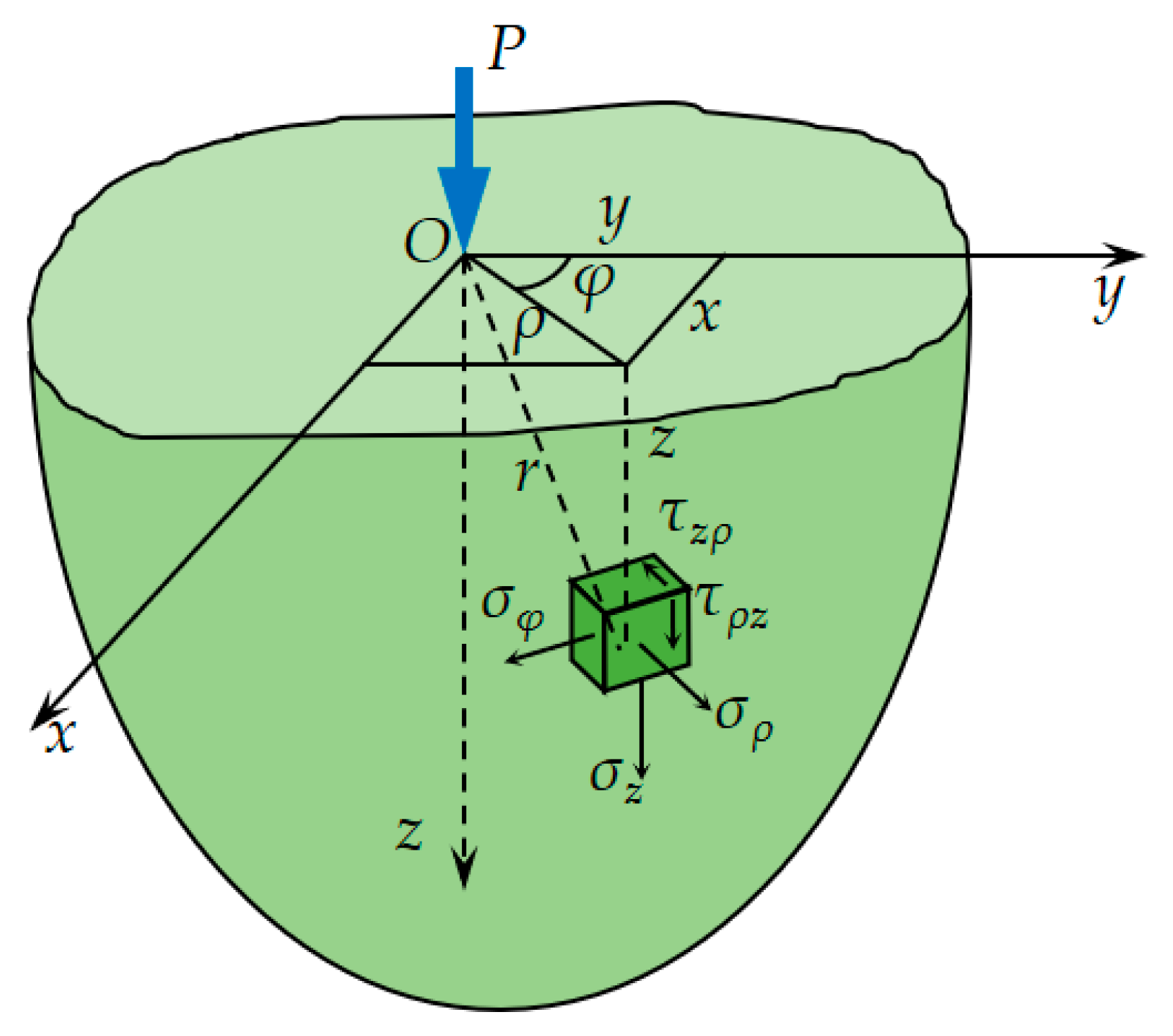
Figure 6.
The relationship between Fcr and for different materials. The mechanical parameters of the materials were obtained by Zhou [45].
Figure 6.
The relationship between Fcr and for different materials. The mechanical parameters of the materials were obtained by Zhou [45].
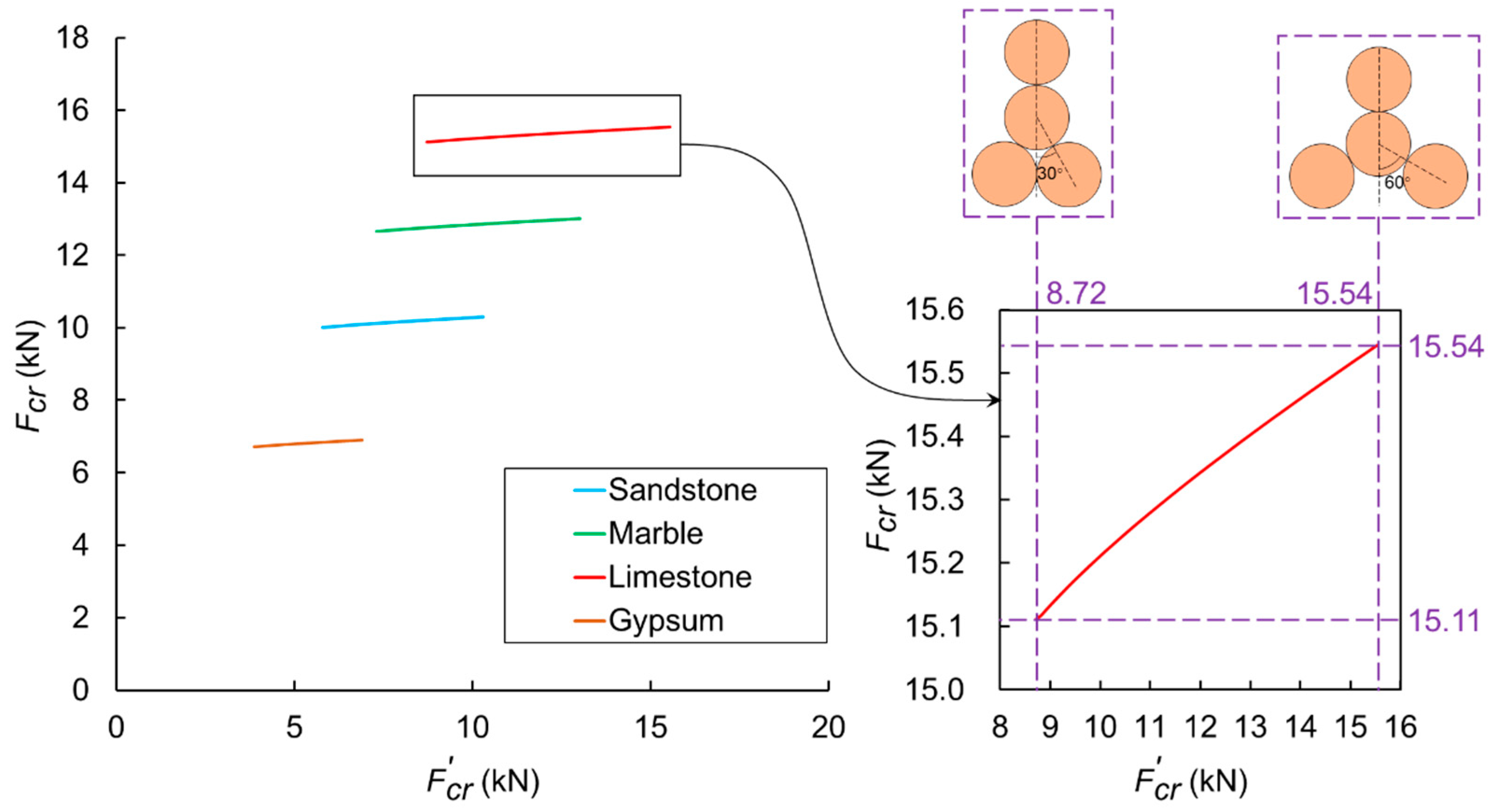
Figure 7.
Some of the apparatuses used were as follows: (a) the rock rheological testing system and (b) the self-developed fixture. The restraint bearing can be adapted to spheres with different particle sizes by adjusting its size. All arc-shaped supports and force sensors are movable. The distance between the two lateral baffles can be adjusted freely. The front and rear baffles are used to assist in fixing the position of Particle I and do not exert forces on the sphere.

Figure 8.
A sketch of the breakage form for Particle I and the stress state of the conical core vertex at the contact point between Particles I and II.
Figure 8.
A sketch of the breakage form for Particle I and the stress state of the conical core vertex at the contact point between Particles I and II.

Figure 9.
Statistical results of the conical core sizes: (a) height of the conical core and (b) bottom area of the conical core. Each result is an average of three repeated tests with a criterion error. The conical cores caused by Particles II, III, and IV are numbered ①, ②, and ③.
Figure 9.
Statistical results of the conical core sizes: (a) height of the conical core and (b) bottom area of the conical core. Each result is an average of three repeated tests with a criterion error. The conical cores caused by Particles II, III, and IV are numbered ①, ②, and ③.
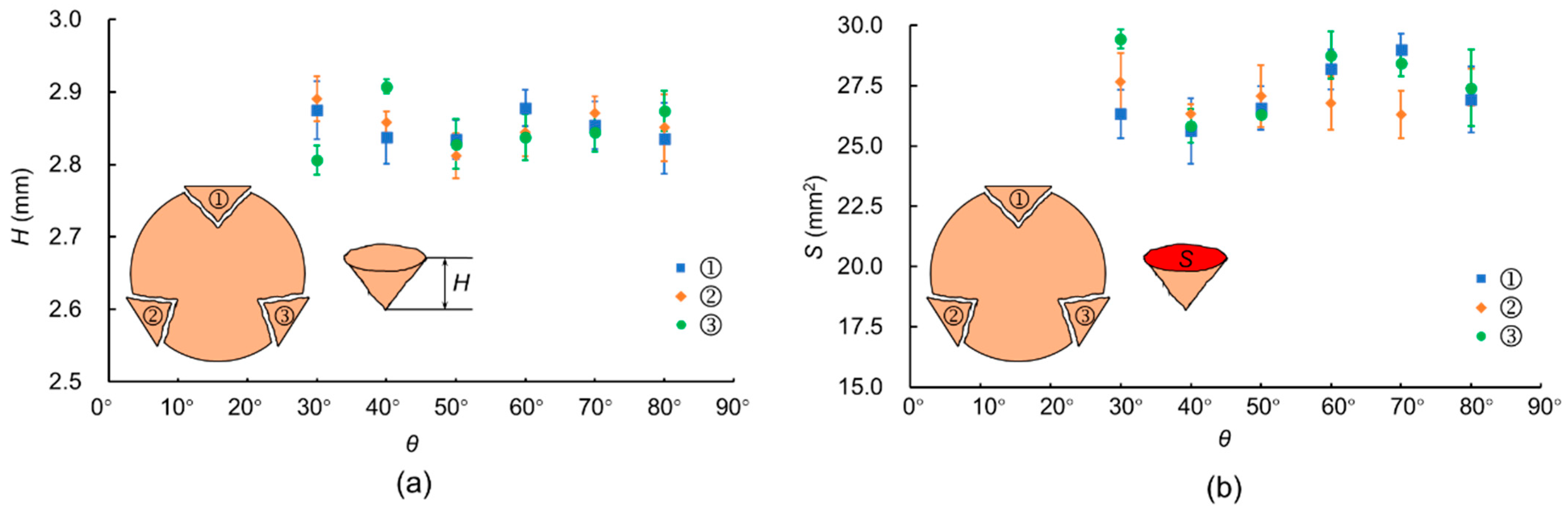
Figure 10.
The relationship between Fcr and θ both theoretically and experimentally. The green dashed lines indicate a 20% range.
Figure 10.
The relationship between Fcr and θ both theoretically and experimentally. The green dashed lines indicate a 20% range.

Figure 11.
A diagram of crushing morphology of cylindrical particles under different contact locations [40].
Figure 11.
A diagram of crushing morphology of cylindrical particles under different contact locations [40].
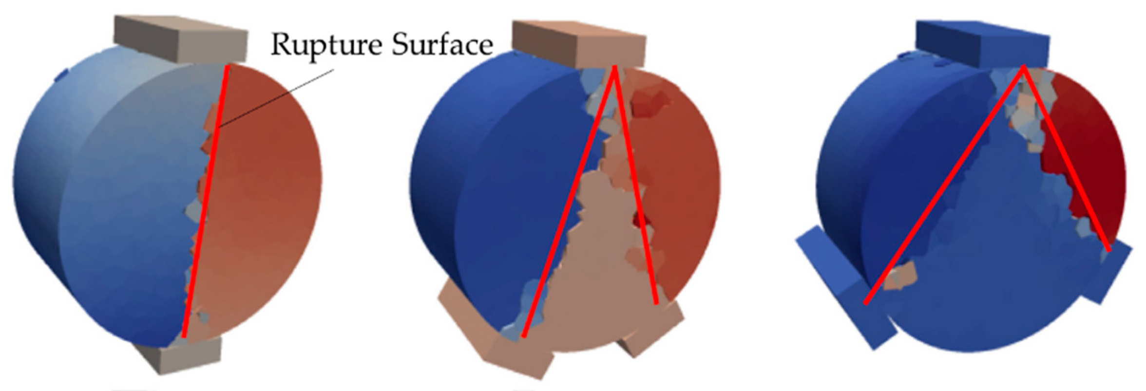
Figure 12.
Fracture morphology of a cylindrical particle under three point loads.

Table 1.
Physical parameters of gypsum.
| Unconfined Compressive Strength | Young’s Modulus | Poisson Ratio | Tensile Strength | Crushing Modulus |
|---|---|---|---|---|
| 54.6 MPa | 5.4 GPa | 0.26 | 2.9 MPa | 11.5 GPa |
Publisher’s Note: MDPI stays neutral with regard to jurisdictional claims in published maps and institutional affiliations. |
© 2021 by the authors. Licensee MDPI, Basel, Switzerland. This article is an open access article distributed under the terms and conditions of the Creative Commons Attribution (CC BY) license (https://creativecommons.org/licenses/by/4.0/).
Share and Cite
MDPI and ACS Style
Niu, Y.; Li, L.; Zhang, Y.; Yu, S. Mechanism of the Breakage of Spherical Gypsum Particles under 3-Point Contact Conditions. Processes 2021, 9, 1029. https://doi.org/10.3390/pr9061029
AMA Style
Niu Y, Li L, Zhang Y, Yu S. Mechanism of the Breakage of Spherical Gypsum Particles under 3-Point Contact Conditions. Processes. 2021; 9(6):1029. https://doi.org/10.3390/pr9061029
Chicago/Turabian StyleNiu, Yiran, Lin Li, Yanwei Zhang, and Shicai Yu. 2021. "Mechanism of the Breakage of Spherical Gypsum Particles under 3-Point Contact Conditions" Processes 9, no. 6: 1029. https://doi.org/10.3390/pr9061029
Note that from the first issue of 2016, this journal uses article numbers instead of page numbers. See further details here.