Optimization of the Melting Performance of a Thermal Energy Storage Unit with Fractal Net Fins

1
MIIT Key Laboratory of Thermal Control of Electronic Equipment, School of Energy and Power Engineering, Nanjing University of Science and Technology, Nanjing 210094, China
2
Key Laboratory of Energy Thermal Conversion and Control of Ministry of Education, School of Energy and Environment, Southeast University, Nanjing 210096, China
3
Nanjing University and Yancheng Academy of Environmental Protection Technology and Engineering, Yancheng 224000, China
*
Author to whom correspondence should be addressed.
Processes 2019, 7(1), 42; https://doi.org/10.3390/pr7010042
Submission received: 22 November 2018
/
Revised: 26 December 2018
/
Accepted: 29 December 2018
/
Published: 15 January 2019
(This article belongs to the Section Advanced Digital and Other Processes)
Abstract
:In this study, fractal net fins were introduced to improve the melting performance of a thermal energy storage unit. A transient model for melting heat transfer for phase change material (PCM) was presented and numerically analyzed, to study the melting performance in a thermal energy storage unit using fractal net fins. The melting phase change process was modelled using the apparent heat capacity method. The evolutions of temperature and the liquid fraction in the thermal energy storage unit were investigated and discussed. The effects of the length and width ratios of the fractal net on melting performance were analyzed to obtain the optimal fin configuration. The results indicated that the fractal net fins significantly enhanced the melting heat transfer performance of the PCM in a thermal energy storage unit. The fractal net fins configuration was optimal when the length and width ratios of the fractal net were 0.5. The temperature response at the corner points of the fractal net fins was faster than that in the central points.
1. Introduction
In recent years, thermal energy storage systems have become crucial in handling energy supply imbalances and realizing the sustainable utilization of energy. Thermal energy storage technology allows excess thermal energy produced at one time to be made available for use at a later time; therefore, it has been widely applied in the areas of electronics cooling [1,2], waste heat utilization [3], chemical processing [4], biomedical engineering [5,6], and so forth. Furthermore, some renewable energies can be stored in the form of thermal energy for sustainable use. The latent heat storage system with phase change material (PCM) is regarded as a promising technology, because it absorbs large amounts of heat at an almost constant temperature. The PCM continues to absorb heat without a significant rise in temperature until all the material is transformed to the liquid phase. However, owing to the highly non-linear characteristics of the solid–liquid or liquid–solid phase transition processes caused by the complicated solid–liquid interface movement, it is important to fully understand the solid–liquid or liquid–solid phase change heat transfer processes.
Commonly used energy storage devices include coil type energy storage tanks. According to the coil-type structure characteristics, there exists the shell-tube [7], U-tube [8], fin tube [9,10], and spiral tube [11], among others. Heat transfer fluid (HTF) circulates in the coil, while PCM stores or releases energy outside the coil. The surface of the coil is the heat exchanger surface between the HTF and PCM. Owing to the limited capacity of the coil and the uneven spatial distribution, the traditional energy storage device has poor heat transfer performance, and has some dead zones of heat transfer. In addition, PCMs generally have the disadvantages of poor thermal conductivity, low energy storage/release efficiency, and a heat transfer unit that is too large, which leads to a larger temperature gradient inside the PCM during the working process, increasing the energy loss of heat transfer and hindering the application of PCMs in thermal energy storage. A wide range of approaches have been applied to enhance the heat transfer performance of PCMs, including dispersing particles [12,13,14], adding fins [15,16], metal foam [17,18,19], composite methods [20,21], and more, which have proven that adding high thermal conductivity materials in various forms improves the heat transfer performance of the PCMs to a certain extent. After optimizing their performance, PCMs will have wider application prospects in the fields of building energy conservation, waste heat recovery, thermal protection of electronic devices, solar power plants, and so forth. Therefore, it is necessary to design a new and efficient thermal conduction enhanced energy storage unit.
It is generally accepted that fractal geometry has the intrinsic advantages of minimized flow resistance [22,23] and strong heat transfer capability [24,25]. Therefore, there has been successful application of a fractal structure to the design of highly efficient heat exchangers [26,27], chemical reactors [28], heat sinks [29,30], and fluid distributors [31,32,33]. It was proven that fractal geometry can achieve a significant increase in the heat transfer area and flow access, with the increase in the fractal levels [34,35]. Consequently, the heat transfer efficiency is improved, the efficiency of energy storage or energy release is enhanced, and the energy loss is reduced. Thus, a fractal net structure is used to enhance the thermal conductivity of thermal energy storage units and to improve the storage capacity, temperature uniformity, and space utilization of latent heat energy storage devices. The optimized thermal energy storage unit can meet the stability and reliability requirements of energy supply to the greatest extent, thereby achieving energy saving and power saving.
Herein, fractal net fins were introduced to optimize the phase change heat transfer between the HTF and PCM (see Figure 1). High thermal conductivity materials were constructed using fractal net fins, and unsteady mathematical models concerning latent heat storage performance were developed and investigated. The effects of different energy storage configurations on energy storage efficiency were compared and discussed. The optimal configuration of the fractal net was designed. Moreover, the temperature and phase distribution were illustrated and analyzed, being the basis for the optimal design of a highly efficient latent heat transfer device.
2. Melting in the Thermal Energy Storage Unit with Fractal Net Fins
The thermal energy storage unit with fractal net fins consists of a shell, fractal net fins, PCM, and HTF (see Figure 2a). In the comparison structure shown in Figure 2b, the sum area of the four fins connecting the shell and the one-level fractal net fins were equal to the sum areas of all the fins in the four-level fractal net fins, except in the one-level fractal net fins. The areas of the four fins connecting the shell and the one-level fractal net fins were equal.
2.1. Fractal Net Configuration
Fractals commonly exhibit similar patterns at increasingly small scales [36]. The fractal net fins are constructed by a recursive algorithm, and the level of recursion is theoretically infinite. The construction process of fractal net fins is shown in Figure 3. The fractal net fins have k levels; k ≥ 1 and k is an integer. The divergence coefficient is N = 4 for each level of fractal net fins; that is, the j level of fractal net fins generates four fractal net fins at the j + 1 level, the center of which is located at the four top angles of the j level of the fractal net fins. L0 and W0 are the initial length and width of the one-level fractal net fins, respectively. The length ratio between the upper and lower levels of the fractal net fins is RL = Lj+1/Lj, where Lj+1/Lj is the length ratio of the upper and lower levels of the fractal net fins. The length of k level fractal net fins is Lj = L0RLj, j = 0, 1, 2,…, k − 1. The width ratio between the upper and lower levels of the fractal net fins is RW = Wj+1/Wj, where Wj+1/Wj is the width ratio of the upper and lower levels of the fractal net fins. The width of k level fractal net fins is Wj = W0RW j, j = 0, 1, 2,…, k − 1.
2.2. Theoretical Model
This paper aims to enhance melting heat transfer in a thermal energy storage unit by the use of fractal net fins. Owing to the fractal net, there are lots of fast heat flow paths over the whole thermal energy storage unit, so the strong and weak heat flows are efficiently allocated. Owing to the fractal fin, the PCM is confined inside a small space (i.e., the interval between fins is small), so the thermodynamic heat transfer phenomena is conduction dominated. In this case, the unsteady melting heat transfer is modeled neglecting the natural convection of PCM.
To elucidate the role of fractal net fin configuration on the heat transfer performance of a thermal energy storage unit, a two-dimensional liquid-solid two phase heat and mass transfer model was developed. The physical models of thermal energy storage unit with fractal net fins (k = 4) and ordinary fins are shown in Figure 2. The areas of fractal net fins and ordinary fins in the thermal energy storage unit are identical; that is, the volume of PCM in the thermal energy storage unit is identical. In the thermal energy storage unit with fractal net fins, HTF flows outside the shell as a cold or heat source, while water is used to fill in the shell as a PCM. On the one hand, the shell directly contacts with the PCM to transfer the heat from HTF. Meanwhile, the shell transfers the cooling capacity to the fractal net fins through the cross fins. The cooling capacity transferred in all levels with the fractal net fins follows the law of graded expansion; that is, the cooling capacity is transferred from one level to the k level of fractal net fins in turn, and each level has multi-directional thermal conduction, which ensures the rapid transfer of cooling capacity from points (surfaces) to surfaces (points) while storing or releasing energy. In this process, heat is conducted from the fractal net fins to the PCM, and the cooling capacity is stored in the PCM. When releasing energy, the heating capacity stored in the PCM in the thermal energy storage unit is transferred along the fractal net fins via thermal conduction. Due to the temperature difference between HTF and PCM, the heating capacity is continuously gathered to the shell. Theoretically, a large quantity of HTF is used with the constant temperature flows along the axis direction of the thermal energy storage unit, so it is reasonable to assume that the thermal boundary condition is a constant temperature boundary.
The shell and fractal net fins are all square, the shell length is 235 mm, the maximum length of the fractal net fins is 100 mm, and the minimum length of the fractal net fins is 12.5 mm when k = 4. The thermal conductivity (λ), specific heat capacity (cp), and density (ρ) of copper and water, as well as the latent heat (Lat) and phase transition temperature (Tm) of water, are listed in Table 1.
Some assumptions are made in order to simplify the calculation: ① The radiation effects in the shell space are neglected; ② The contact thermal resistance between the PCM and fractal net fins is ignored; ③ There are three possible zones in the whole melting process—the solid zone, mushy zone and liquid zone; ④ The properties of PCM are linear with temperature in the mushy zone; ⑤ the phase change occurs in a temperature interval between Tm − ΔT/2 and Tm + ΔT/2, where ΔT = 0.1 K is adopted in the simulation; ⑥ The volume expansion when water solidifies into ice is ignored; that is, ρs = ρl.
Based on the above assumptions, the phase change from solid state to liquid state was modeled via the enthalpy-porosity formulation. Due to the fractal net fins, the PCM is confined in a small space, so the thermodynamic heat transfer phenomena is conduction dominated. Therefore, the unsteady melting heat transfer was modeled with neglect of the natural convection of PCM. The governing equation of the unsteady thermal conduction accompanied with melting phase change in a thermal energy storage unit with fractal net fins is written as:
It is important to note that after τ = 0, the temperature of the metal fins was determined from the equation of heat conduction (see Equation (2)), and the temperature of PCM was determined from the enthalpy equation (see Equation (1)). In the enthalpy-porosity method the liquid fraction, which is 1 when the water is liquid and 0 when the water is solid, was applied to characterize the solid-liquid interface. The liquid fraction ε was used to describe the mushy zone so as to explicitly track the phase interface. The mushy zone is deemed to be a porous region, the porosity of which was set as the liquid fraction. The expression of the liquid fraction ε is given by:
In the liquid and mushy zone, the enthalpy h of PCM in Equation (4) includes the total sensible heat and the total latent heat, which is expressed by:
where the subscript p represents PCM. The subscripts s and l represent the solid state and liquid state of PCM, respectively.
Transient thermal conduction problems require a set of constraints, namely initial and boundary conditions, to obtain the unique solution. The initial temperature of the whole computational domain was −20 °C. The initial liquid phase rate ε was 0 at the beginning of melting. The shell temperature was constant for the thermal energy storage unit with fractal net fins.
Initial condition:
Boundary conditions:
x = 0 or x = H, T = Tw
y = 0 or y = H, T = Tw
There is a thermal equilibrium between the fractal net fins and the PCM which is given by:
where Ω are the boundaries between the fractal net fins and the PCM, and n represents the normal direction of heat flux. The cross section in the XY direction of the thermal energy storage unit is square, the side length of which is H (see Figure 2b as an example).
The solid-liquid interface also satisfies the law of conservation of energy, which is expressed as follows:
where τ is time, L is the moving distance of the solid-liquid interface, Lat is latent heat, and n denotes the normal direction at the solid-liquid interface.
The finite element method was applied to solve the governing equations of unsteady thermal conduction accompanied with phase change. According to the sophisticated pore structures of the fractal net fins, the unstructured meshes (triangular elements) were applied to all the computational regions.
Issues of mesh refinement and the independence test, as well as convergence, were paid special attention for the highly nonlinear model. Mesh refinement was carried out at severe temperature variations, where the PCM and fractal net fins were in contact (see Figure 2a). In order to ensure the efficiency of the calculations and the accuracy of calculation results, a series of mesh sizes (16,942, 31,556, 46,750, 56,794, 63,138, 66,706 and 70,954) were tried to ensure the present numerical results were independent of the mesh size. Duration time is the time consumption when the PCM completely melts in the thermal energy storage unit. The relative error of the duration time in the thermal energy storage unit with the fractal net fins (RL = 0.5, RW = 0.5) was less than 0.98% when the mesh number was greater than 56,794. The point is represented by the symbol of a star in Figure 4b. In fact, the error of duration time in a certain range (probably less than 2%, in our case 0.98%) can be considered to mean meshing is sufficient. It is not necessary to obtain the optimal mesh number when the duration time is completely unchanged. Therefore, a mesh number of 56,794 was applied to the simulations. Moreover, the mesh refinement can capture more details of heat transfer between PCM and fins, as well as phase change heat transfer, which makes the heat transfer sufficient, so the duration time decreased with the increase of the mesh number.
2.3. Model Verification
The temperature variations from our present model were compared with the experimental results [37], which concern heat transfer performance of a PCM embedded in porous metals. The geometry and operating conditions of our model were consistent with the experiment (see Figure 5a); that is, the PCM (Paraffin RT 58) was embedded in the metal foam (copper, 95% porosity, 200 × 25 mm), and the thermo-physical properties of the PCM were as follows: The melting temperature was 321–335 K, the latent heat was 181 kJ/kg, the thermal conductivity was 0.2 W/(m·K), the specific heat was 201 kJ/kg, and the dynamic viscosity was 0.0269 Pa·s. The heat flux at the bottom of the two-dimensional model was 1.6 kW/m2, and the rest of boundaries were exposed to the room temperature (293 K). As shown in Figure 5b, temperature evolutions of the sensor (locates at 8 mm above the bottom) of our present model agreed well with that of the experiment, which proves the rationality of our model. Moreover, the temperature difference between the simulation and the experiment is probably because the pores of the metal foam used in the experiment were not completely connected, there may be some closed pores, and there was no PCM in the closed pores, while in the simulation the pores distribution of the metal foam was uniform and the PCM filled in the pores. Therefore, since the PCM has the effect of slowing down the temperature change, the average temperature of the experiment is higher than that of the simulation during the phase transition (see 1250–3500 s in Figure 5b).
3. Results and Discussion
The melting processes of a thermal energy storage unit with fractal net fins and ordinary fins were investigated. The areas of fractal net fins and ordinary fins in the thermal energy storage unit were identical. The initial temperature was 253.15 K, and the initial liquid fraction ε was 0. The temperature of HTF was constant, so the boundary condition was a constant wall temperature; that is, 293.15 K. The phase transition temperature of PCM was 273.15 K.
3.1. Melting Behaviors of the Thermal Energy Storage Unit
The energy storage characteristics of PCM, including the phase change rate and the shape of the phase change interface, can be improved by adding high thermal conductivity materials. Figure 6 shows the temperature and liquid fraction evolution of PCM in the thermal energy storage unit with fractal net fins and ordinary fins during the melting processes. It is illustrated in Figure 6a that each sub-grid in the fractal net structures designed in this paper can transfer heat from two directions with the next level fractal net fins, which shortens the distance of heat transfer and realizes the heat transfer from point (surface) to surface (point). Meanwhile, the fractal net fins were distributed evenly in the shell, which resulted in a significant increase of the effective heat transfer area of the thermal energy storage unit in the finite space. In addition, since the PCM was divided into many relatively independent heat transfer units, the dead zone of heat transfer in the thermal energy storage unit was effectively reduced, and the effective heat conduction resistance between the fins and the PCM was reduced. It is worth noting that the dead zone of heat transfer is the zone far from the boundary of the heat source, where heat reaches the slowest; that is, the zone where the phase change occurs last. Therefore, no matter the energy storage or release process in the thermal energy storage unit, it is reflected from the temperature cloud chart so that the temperature distribution is more uniform, the temperature gradient of the PCM is reduced, and the energy utilization rate is improved. It is noteworthy that the energy utilization rate refers to the ratio of the energy effectively utilized by the thermal energy storage units to the actual energy consumption. Fractal net fins improve the thermal conductivity of the thermal energy storage unit, so energy can be stored and utilized efficiently, thus reducing unnecessary energy loss, so the energy utilization rate will be improved accordingly.
The liquid fraction evolutions of PCM in the thermal energy storage unit with fractal net fins during the melting processes are shown in Figure 6a, and those of ordinary fins are shown in Figure 6b. The heat required for melting was transferred from the shell to the fractal net fins and PCM. Since the heat conductivity of the fins is much higher than that of PCM, the heat was conducted rapidly along the fins and then the PCM around the fins. As shown in Figure 7, it took about 510 s for the thermal energy storage unit with the fractal net fins to basically complete the phase transition, while it took 1130 s for the thermal energy storage unit with the ordinary fins. Note that the exchange surface was increased by 15 in the case of k = 4, however the large variation in the exchange surface area and the efficiency of energy storage are not proportional. This is because the fractal net distribution of high thermal conductivity material has a beneficial effect on the energy gradient distribution. Though the area of the fractal net fins was identical to that of the ordinary fins, the phase transitions of PCM in the thermal energy storage unit with the fractal net fins and the ordinary fins were basically carried out simultaneously along the four directions (taking 1/4 thermal energy storage unit for example). Two sides of the 1/4 thermal energy storage unit are the high thermal conductivity fins, and the other two sides are the shells.
3.2. Optimal Fractal Net Fin Configuration: Effect of Length Ratio RL and Width Ratio RW
Figure 8 presents the role of length ratio RL and width ratio RW on the temperature variations of the representative points (central points) and Q, which is the input heat to the whole thermal energy storage unit, so it is expressed by:
If RL > 0.52, the fractal net fins will collide with each other, so the fractal net fins are unable to be constructed successfully. Therefore, 0.52 is a critical value in that RL must be less than 0.52. If the length ratio is too small, the distribution uniformity of the fractal net fins will decrease. Therefore, the temperature and input heat of the thermal energy storage unit when RL = 0.4 and RL = 0.5 were investigated in Figure 8a. RL was obtained via net a fractal algorithm, which is described in Section 2.1. Through this algorithm we can intuitively obtain the generated fractal net fins on the computer. Therefore, we can investigate the energy storage characteristics of different fractal net fins, and obtain the optimized fin configuration. It is illustrated that the fractal net fins with a large length ratio have more high thermal conductivity materials and wider fin coverage than those with small length ratio. Therefore, the temperature of the central point in the thermal energy storage unit when RL = 0.5 rose more significantly, reaching equilibrium temperature at about 750 s, while the temperature of the central point in the thermal energy storage unit when RL = 0.4 was stable at around 1500 s. However, for the fractal net fins with the length ratios RL = 0.4 and RL = 0.5 (the total length of the fractal net fins with RL = 0.4 was 13.4% shorter than that with RL = 0.5), the difference of input heat of the thermal energy storage unit during the melting processes was very small. In the energy release stage, the input heat Q of the thermal energy storage unit with the fractal net fins with RL = 0.5 was slightly larger than that with RL = 0.4. When the input heat Q reached the equilibrium state at about 600 s, the input heat between them was basically the same. The width ratio RW of the fractal net fins also had a significant effect on the duration of the stabilization of the temperature of the central points and heat transfer capacities of the thermal energy storage unit during the melting processes (see Figure 8b). A larger width ratio of fractal net fins indicated a higher proportion of high thermal conductivity materials, which resulted in faster temperature variations. However, the variation trends of the input heat were opposite to that of the width ratio. The input heat of thermal energy storage unit decreased with the increase of the width ratio. A larger width ratio indicated a larger fractal net fin area, correspondingly leading to a smaller proportion of the PCM, thus the input heat was reduced. That is, the volume of PCM in the thermal energy storage unit with RL = 0.4 or 0.5 varied very little when the fin width was constant, so the different temperature curves in Figure 8a give superimposed Q curves. On the other hand, the volume of PCM in the thermal energy storage unit with RW = 0.45, 0.5 or 0.7 varied relatively more when the fin length was constant. This was due to the width of the fin being much smaller than the length of the fin. Therefore, when RL = 0.5 and RW = 0.5, the thermal energy storage unit with the fractal net fins had the optimal heat transfer and energy release effect.
3.3. Dynamic Temperature Response
To further understand the melting behavior of PCM in a thermal energy storage unit with fractal net fins and ordinary fins, the dynamic temperature variations of the representative points (corner points and central points) are shown in Figure 9a. Figure 9b and c represent the positions of the representative points of the two types of fin configurations (fractal net fins and ordinary fins) with red dots, respectively. The reason for choosing these two points as the representative points is that they are in relatively unfavorable positions for heat transfer, which we inferred from the liquid fraction cloud maps of PCM in the thermal energy storage unit (see Figure 6). The corner point is at the midpoint of the connection between the upper right corner of the two-level fractal net fins and the upper right corner of the three-level fractal net fins (see Figure 9b). The corner point position of the thermal energy storage unit with ordinary fins is identical to that of the thermal energy storage unit with fractal net fins. The central points are in the center of the thermal energy storage unit, whether it is the thermal energy storage unit with fractal net fins or ordinary fins. It is clearly shown in Figure 9a that the heat transfer at the corner points is generally better than that at the central points. This is because the corner points are closer to the shell, which is the heat source of the thermal energy storage unit and thus gains more heat flux. Compared with the central points, the constant temperature durations of PCM during the phase transition at the corner points were relatively short. It is indicated by the figure that the fractal net fins played an active role in the improvement of the temperature uniformity and heat transfer of the thermal energy storage unit. Inside the thermal energy storage unit, the duration time of melting phase change at the corner region was shorter when compared with the central region. With the fractal net fins, there was a faster temperature response: The temperature in both the central region and corner region changed dramatically. This implies that the duration time of the melting phase change process was reduced with the use of fractal net fins. However, once the phase transition was completed, the temperature at the central points varied very rapidly. This is because the central points receive heat from the high thermal conductivity boundary in four directions simultaneously. In addition, the heat transfer of the thermal energy storage unit with fractal net fins was better than that with ordinary fins at the central points of the thermal energy storage unit. It took about 500 s for PCM in the thermal energy storage unit with fractal net fins to complete the phase transition, while it took about 1100 s with the ordinary fin. It is fully indicated that the heat transfer efficiency of a thermal energy storage unit with fractal net fins is higher than that with ordinary fins when the area of the fractal net fins is identical to that of the ordinary fins. A higher heat transfer efficiency of the thermal energy storage unit was achieved when k = 4, RL = 0.5, and RW = 0.5, compared with other fin configurations, such as k = 1, 2, 3 or ordinary fins.
3.4. Effect of Initial Temperature Difference
The initial temperature difference has a significant effect on the duration time of PCM in a thermal energy storage unit (see Figure 10). The initial temperature difference is the final temperature minus the initial temperature. In this case, the initial temperature was fixed (−20 °C), and only the final temperatures (10 °C, 15 °C, 20 °C, 25 °C, 30 °C) increased. As expected, the large difference between initial temperature and boundary temperature can result in a large heat flux of melting of PCM in the thermal energy storage unit, thus the duration time of PCM in the thermal energy storage unit—no matter if it has ordinary fins or fractal net fins—is shortened. In addition, it is indicated that under the condition of a constant fin area, a reasonable configuration and arrangement of fins (i.e., fractal net fins) can significantly enhance the heat transfer efficiency of the thermal energy storage unit and shorten the time of phase transition. In other words, when the initial temperature difference is the same, the duration time of PCM in the thermal energy storage unit with the fractal net fins is more than twice as long as that with the ordinary fins. If it takes more than 800 s to melt the same volume of PCM, the thermal energy storage unit with the fractal net fins needs about △T = 30 °C, while the thermal energy storage unit with the ordinary fins needs about △T = 50 °C. Therefore, the fractal net fins greatly improve the heat release performance of thermal energy storage unit.
4. Conclusions
Herein, fractal net fins were used to enhance the melting heat transfer performance of a thermal energy storage unit. The temperature and liquid fraction distributions in the thermal energy storage unit with fractal net fins during the melting processes are presented and compared with ordinary fins. The effect of the length and width ratios of fractal net is analyzed to obtain the optimal configuration for fractal net fins. The effect of the initial temperature difference on melting performance is examined and analyzed as well. The main conclusions are as follows:
- (1)
- The fractal net fins can significantly enhance the melting heat transfer performance of PCM in a thermal energy storage unit. The temperature distribution in the thermal energy storage unit is more uniform, and the temperature gradient of the PCM is reduced and the energy utilization rate is improved. It takes about 510 s for the thermal energy storage unit with fractal net fins to complete the melting phase change, while it takes 1130 s for the thermal energy storage unit with ordinary fins.
- (2)
- The fin configuration in a thermal energy storage unit is optimal when the length and width ratios of fractal net are 0.5. The average temperature of a thermal energy storage unit with a large length ratio increases more significantly. A larger width ratio of the fractal net fin results in the faster temperature variation, and the heat transfer performance of the thermal energy storage unit decreases with the increase of the width ratio. In addition, the heat transfer at the corner points of the thermal energy storage unit is better than that at the central points no matter what the fin configuration.
- (3)
- The initial temperature difference is an important factor affecting the melting performance. A larger initial temperature difference leads to a large heat flux of PCM and shortens the duration time in a thermal energy storage unit no matter what fin configuration is used. When the initial temperature difference is the same, the duration time of PCM in a thermal energy storage unit with ordinary fins is more than twice as long as that with fractal net fins.
Author Contributions
All authors participated to the elaboration of the manuscript. Investigation, methodology and writing-original draft, J.Z.; investigation and validation, C.Y.; software and data curation, T.C.; methodology and supervision, Y.Y.; Data curation, F.W. All the authors discussed the results.
Funding
This research was funded by the National Natural Science Foundation of China (51706101); Key Laboratory of Solar Energy Science and Technology Foundation of Jiangsu Province (KLSST201704) and the Fundamental Research Funds for the Central Universities (No. 30917011328).
Conflicts of Interest
The authors declare no conflict of interest.
References
- Liu, X.; Chen, Y.; Shi, M. Dynamic performance analysis on start-up of closed-loop pulsating heat pipes (clphps). Int. J. Therm. Sci. 2013, 65, 224–233. [Google Scholar] [CrossRef]
- Zhang, C.; Shen, C.; Chen, Y. Experimental study on flow condensation of mixture in a hydrophobic microchannel. Int. J. Heat Mass Transf. 2017, 104, 1135–1144. [Google Scholar] [CrossRef]
- Miró, L.; Gasia, J.; Cabeza, L.F. Thermal energy storage (tes) for industrial waste heat (iwh) recovery: A review. Appl. Energy 2016, 179, 284–301. [Google Scholar] [CrossRef]
- Chen, Y.; Gao, W.; Zhang, C.; Zhao, Y. Three-dimensional splitting microfluidics. Lab Chip 2016, 16, 1332–1339. [Google Scholar] [CrossRef] [PubMed]
- Wang, J.; Sun, L.; Zou, M.; Gao, W.; Liu, C.; Shang, L.; Gu, Z.; Zhao, Y. Bioinspired shape-memory graphene film with tunable wettability. Sci. Adv. 2017, 3, e1700004. [Google Scholar] [CrossRef]
- Wang, J.; Gao, W.; Zhang, H.; Zou, M.H.; Chen, Y.P.; Zhao, Y.J. Programmable wettability on photocontrolled graphene film. Sci. Adv. 2018, 4, eaat7392. [Google Scholar] [CrossRef]
- Zheng, Z.-J.; Xu, Y.; Li, M.-J. Eccentricity optimization of a horizontal shell-and-tube latent-heat thermal energy storage unit based on melting and melting-solidifying performance. Appl. Energy 2018, 220, 447–454. [Google Scholar] [CrossRef]
- Xiong, T.; Wang, Y.; Yang, X. Numerical investigation of dynamic melting process in a thermal energy storage system using u-tube heat exchanger. Adv. Mech. Eng. 2017, 9. [Google Scholar] [CrossRef]
- Mahdi, J.M.; Lohrasbi, S.; Ganji, D.D.; Nsofor, E.C. Accelerated melting of pcm in energy storage systems via novel configuration of fins in the triplex-tube heat exchanger. Int. J. Heat Mass Transf. 2018, 124, 663–676. [Google Scholar] [CrossRef]
- Amagour, M.E.H.; Rachek, A.; Bennajah, M.; Ebn Touhami, M. Experimental investigation and comparative performance analysis of a compact finned-tube heat exchanger uniformly filled with a phase change material for thermal energy storage. Energ. Convers. Manag. 2018, 165, 137–151. [Google Scholar] [CrossRef]
- Zheng, X.; Xie, N.; Chen, C.; Gao, X.; Huang, Z.; Zhang, Z. Numerical investigation on paraffin/expanded graphite composite phase change material based latent thermal energy storage system with double spiral coil tube. Appl. Therm. Eng. 2018, 137, 164–172. [Google Scholar] [CrossRef]
- Liu, X.; Rao, Z. Experimental study on the thermal performance of graphene and exfoliated graphite sheet for thermal energy storage phase change material. Thermochim. Acta 2017, 647, 15–21. [Google Scholar] [CrossRef]
- Das, N.; Kohno, M.; Takata, Y.; Patil, D.V.; Harish, S. Enhanced melting behavior of carbon based phase change nanocomposites in horizontally oriented latent heat thermal energy storage system. Appl. Therm. Eng. 2017, 125, 880–890. [Google Scholar] [CrossRef]
- Ebadi, S.; Tasnim, S.H.; Aliabadi, A.A.; Mahmud, S. Melting of nano-pcm inside a cylindrical thermal energy storage system: Numerical study with experimental verification. Energ. Convers. Manag. 2018, 166, 241–259. [Google Scholar] [CrossRef]
- Jannesari, H.; Abdollahi, N. Experimental and numerical study of thin ring and annular fin effects on improving the ice formation in ice-on-coil thermal storage systems. Appl. Energy 2017, 189, 369–384. [Google Scholar] [CrossRef]
- Augspurger, M.; Choi, K.K.; Udaykumar, H.S. Optimizing fin design for a pcm-based thermal storage device using dynamic kriging. Int. J. Heat Mass Transf. 2018, 121, 290–308. [Google Scholar] [CrossRef]
- Deng, Z.; Liu, X.; Zhang, C.; Huang, Y.; Chen, Y. Melting behaviors of pcm in porous metal foam characterized by fractal geometry. Int. J. Heat Mass Transf. 2017, 113, 1031–1042. [Google Scholar] [CrossRef]
- Zhang, C.; Wu, L.; Chen, Y. Study on solidification of phase change material in fractal porous metal foam. Fractals 2015, 23, 1540003. [Google Scholar] [CrossRef]
- Yang, X.; Feng, S.; Zhang, Q.; Chai, Y.; Jin, L.; Lu, T.J. The role of porous metal foam on the unidirectional solidification of saturating fluid for cold storage. Appl. Energy 2017, 194, 508–521. [Google Scholar] [CrossRef]
- Jourabian, M.; Farhadi, M.; Rabienataj Darzi, A. Constrained ice melting around one cylinder in horizontal cavity accelerated using three heat transfer enhancement techniques. Int. J. Therm. Sci. 2018, 125, 231–247. [Google Scholar] [CrossRef]
- Mahdi, J.M.; Nsofor, E.C. Melting enhancement in triplex-tube latent thermal energy storage system using nanoparticles-fins combination. Int. J. Heat Mass Transf. 2017, 109, 417–427. [Google Scholar] [CrossRef]
- Zhang, C.; Chen, Y.; Shi, M. Effects of roughness elements on laminar flow and heat transfer in microchannels. Chem. Eng. Process. 2010, 49, 1188–1192. [Google Scholar] [CrossRef]
- Zhang, C.; Chen, Y.; Deng, Z.; Shi, M. Role of rough surface topography on gas slip flow in microchannels. Phys. Rev. E 2012, 86, 016319. [Google Scholar] [CrossRef] [PubMed]
- Huang, Z.; Hwang, Y.; Radermacher, R. Review of nature-inspired heat exchanger technology. Int. J. Refrig. 2017, 78, 1–17. [Google Scholar] [CrossRef]
- Chen, Y.; Zhang, C.; Shi, M.; Yang, Y. Thermal and hydrodynamic characteristics of constructal tree-shaped minichannel heat sink. AIChE J. 2010, 56, 2018–2029. [Google Scholar] [CrossRef]
- Bejan, A. Shape and Structure, from Engineering to Nature; Cambridge University Press: Cambridge, UK, 2000. [Google Scholar]
- Tarasov, V.E. Heat transfer in fractal materials. Int. J. Heat Mass Transf. 2016, 93, 427–430. [Google Scholar] [CrossRef]
- Chen, Y.; Zhang, C.; Wu, R.; Shi, M. Methanol steam reforming in microreactor with constructal tree-shaped network. J. Power Sources 2011, 196, 6366–6373. [Google Scholar] [CrossRef]
- Zhang, C.; Chen, Y.; Wu, R.; Shi, M. Flow boiling in constructal tree-shaped minichannel network. Int. J. Heat Mass Transf. 2011, 54, 202–209. [Google Scholar] [CrossRef]
- Chen, Y.; Cheng, P. An experimental investigation on the thermal efficiency of fractal tree-like microchannel nets. Int. Commun. Heat Mass Transf. 2005, 32, 931–938. [Google Scholar] [CrossRef]
- He, G.; Kochergin, V.; Li, Y.; Nandakumar, K. Investigations about the effect of fractal distributors on the hydrodynamics of fractal packs of novel plate and frame designs. Chem. Eng. Sci. 2018, 177, 195–209. [Google Scholar] [CrossRef]
- Chen, Y.P.; Deng, Z.L. Hydrodynamics of a droplet passing through a microfluidic t-junction. J. Fluid Mech. 2017, 819, 401–434. [Google Scholar] [CrossRef]
- Liu, X.; Zhang, C.; Yu, W.; Deng, Z.; Chen, Y. Bubble breakup in a microfluidic t-junction. Sci. Bull. 2016, 61, 811–824. [Google Scholar] [CrossRef]
- Zhang, C.B.; Deng, Z.L.; Chen, Y.P. Temperature jump at rough gas-solid interface in couette flow with a rough surface described by cantor fractal. Int. J. Heat Mass Transf. 2014, 70, 322–329. [Google Scholar] [CrossRef]
- Bejan, A. The Physics of Life: The Evolution of Everything; St. Martin’s Press: New York, NY, USA, 2016. [Google Scholar]
- Boeing, G. Visual analysis of nonlinear dynamical systems: Chaos, fractals, self-similarity and the limits of prediction. Systems 2016, 4, 37. [Google Scholar] [CrossRef]
- Tian, Y.; Zhao, C.Y. A numerical investigation of heat transfer in phase change materials (pcms) embedded in porous metals. Energy 2011, 36, 5539–5546. [Google Scholar] [CrossRef]
Figure 1.
Thermal energy storage unit with fractal net fins. HTF: heat transfer fluid; PCM: phase change material.
Figure 1.
Thermal energy storage unit with fractal net fins. HTF: heat transfer fluid; PCM: phase change material.
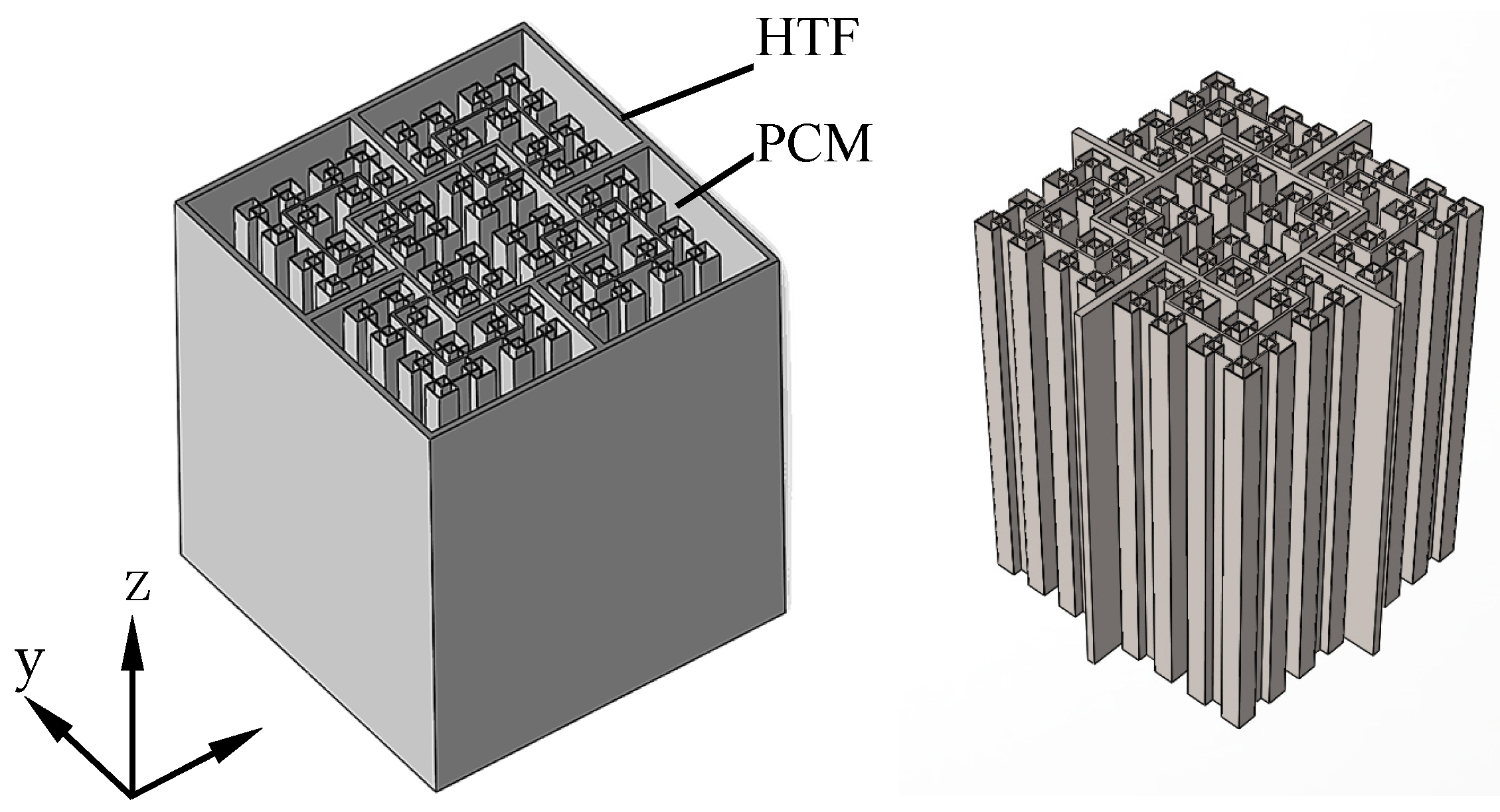
Figure 2.
Schematic of thermal energy storage unit: (a) fractal net fins; (b) ordinary fins.
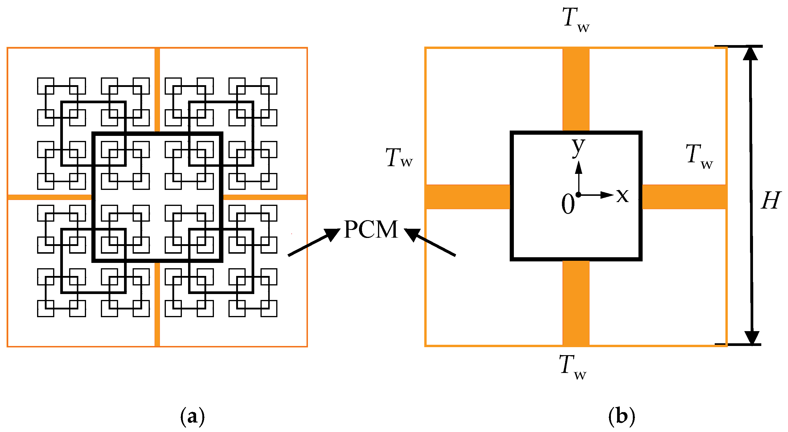
Figure 3.
Fractal net fins, (a–d) are the different level of fractal net fins.

Figure 4.
Mesh optimization: (a) mesh refinement; (b) mesh independence validation.
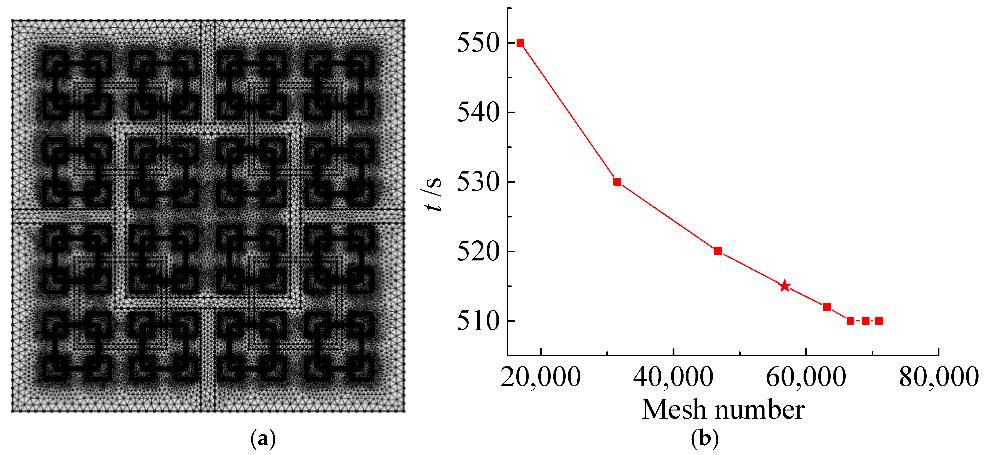
Figure 5.
Comparison between our present model and experiment [37]: (a) physical model; (b) temperature evolution.
Figure 5.
Comparison between our present model and experiment [37]: (a) physical model; (b) temperature evolution.
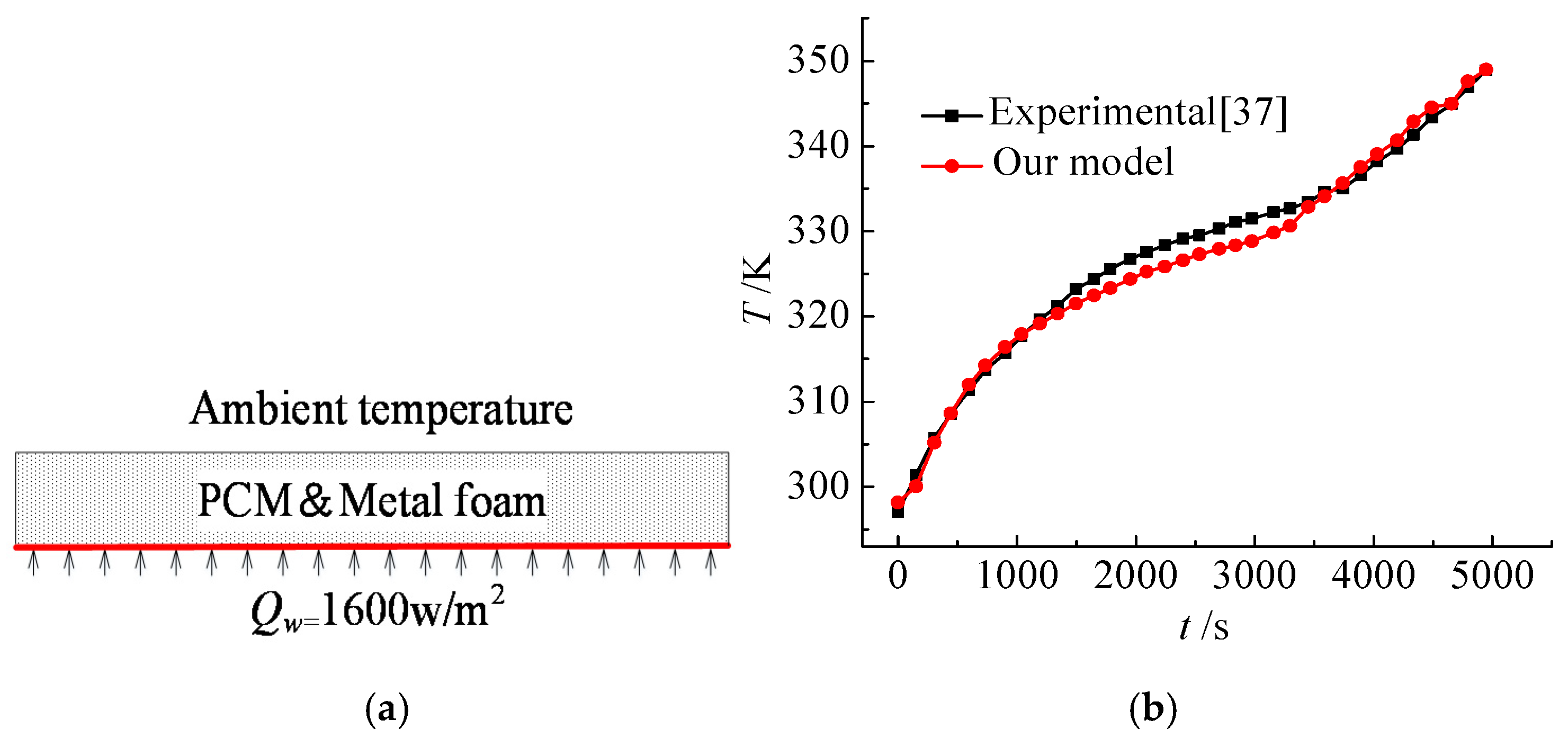
Figure 6.
Temperature and liquid fraction evolution of PCM in the thermal energy storage unit during the melting process: (a) fractal net fins; (b) ordinary fins.
Figure 6.
Temperature and liquid fraction evolution of PCM in the thermal energy storage unit during the melting process: (a) fractal net fins; (b) ordinary fins.

Figure 7.
Duration time of PCM in the thermal energy storage unit with different fin configurations: (a) fractal net fins; (b) ordinary fins.
Figure 7.
Duration time of PCM in the thermal energy storage unit with different fin configurations: (a) fractal net fins; (b) ordinary fins.
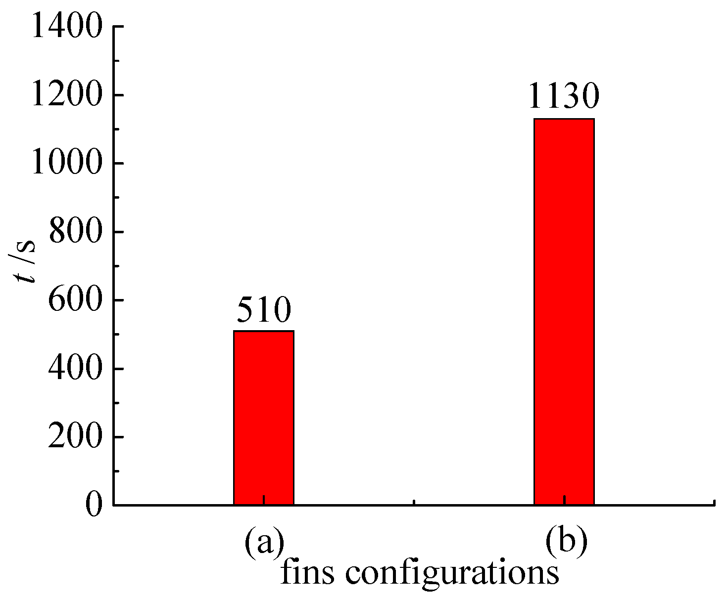
Figure 8.
Effect of fin size on the temperature of the central point and input heat in the thermal energy storage unit during the melting processes: (a) role of RL when RW = 0.5; (b) role of RW when RL = 0.5.
Figure 8.
Effect of fin size on the temperature of the central point and input heat in the thermal energy storage unit during the melting processes: (a) role of RL when RW = 0.5; (b) role of RW when RL = 0.5.
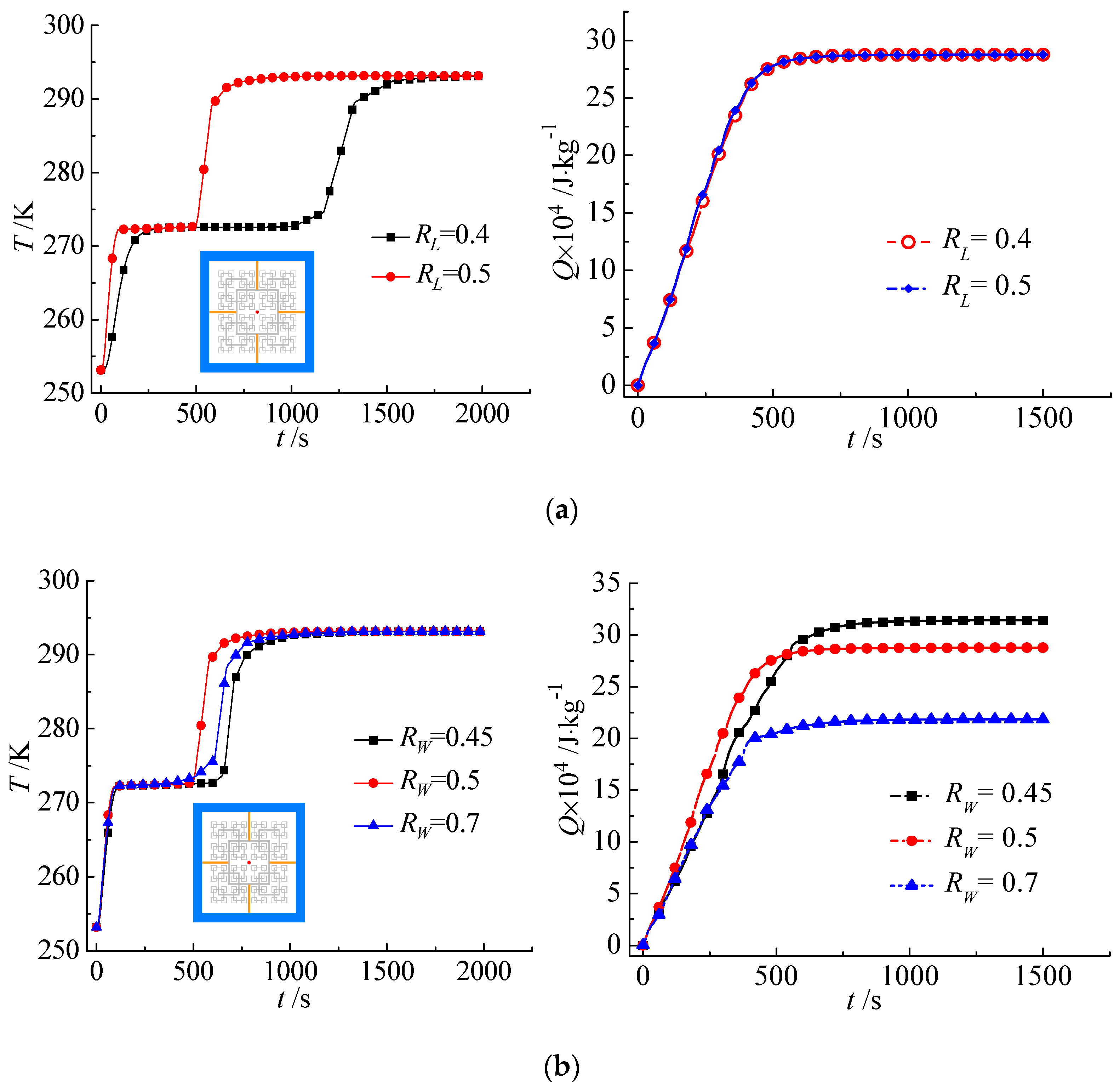
Figure 9.
Temperature variation of representative points (corner points and central points) in a thermal energy storage unit with different fin configurations: (a) temperature evolutions; (b) fractal net fins; (c) ordinary fins.
Figure 9.
Temperature variation of representative points (corner points and central points) in a thermal energy storage unit with different fin configurations: (a) temperature evolutions; (b) fractal net fins; (c) ordinary fins.
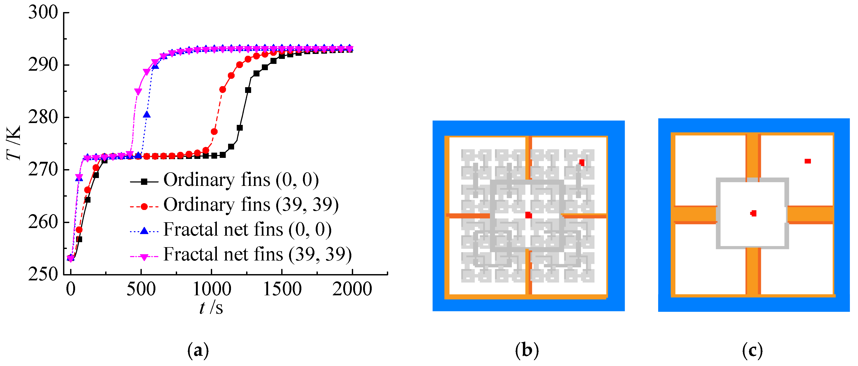
Figure 10.
Effect of initial temperature difference on duration time.


Table 1.
Thermo-physical properties of copper and water.
| Materials | λ/W·(m·K)−1 | cp/J·(kg·K)−1 | ρ/kg·m−3 | Lat/kJ·kg−1 | Tm/K |
|---|---|---|---|---|---|
| Copper | 400 | 385 | 8960 | — | — |
| Water (solid) | 2.22 | 2000 | 900 | 333 | 273.15 |
| Water (liquid) | 0.599 | 4184 | 1000 |
© 2019 by the authors. Licensee MDPI, Basel, Switzerland. This article is an open access article distributed under the terms and conditions of the Creative Commons Attribution (CC BY) license (http://creativecommons.org/licenses/by/4.0/).
Share and Cite
MDPI and ACS Style
Zheng, J.; Yu, C.; Chen, T.; Yu, Y.; Wang, F. Optimization of the Melting Performance of a Thermal Energy Storage Unit with Fractal Net Fins. Processes 2019, 7, 42. https://doi.org/10.3390/pr7010042
AMA Style
Zheng J, Yu C, Chen T, Yu Y, Wang F. Optimization of the Melting Performance of a Thermal Energy Storage Unit with Fractal Net Fins. Processes. 2019; 7(1):42. https://doi.org/10.3390/pr7010042
Chicago/Turabian StyleZheng, Jiayi, Cheng Yu, Taotao Chen, Yanshun Yu, and Fang Wang. 2019. "Optimization of the Melting Performance of a Thermal Energy Storage Unit with Fractal Net Fins" Processes 7, no. 1: 42. https://doi.org/10.3390/pr7010042
Note that from the first issue of 2016, this journal uses article numbers instead of page numbers. See further details here.