3.1. Objectives and General Needs of an OTS for the Bio-Ethanol Plant
The objectives of the OTS were worked out cooperatively with the plant management (Lantmännen Reppe AB). It was agreed that training of plant operators would benefit from a state-of-the-art IT-based solution where a training simulator should be used to make training and education of plant personnel time- and cost-efficient. The means for achieving this should be through the use of a virtual simulation tool, representing the plant and that could allow interaction in real or accelerated time under realistic conditions. It was unanimously agreed that the OTS should be designed using conceptual design principles and that these should render a design solution adaptable to changes in the plant such as other process equipment units or other brands of yeast or enzymes and allow easy adjustment of process model parameters. In addition, the OTS design may possibly serve as a frame for other similar bio-plants.
In particular the OTS shall allow training of
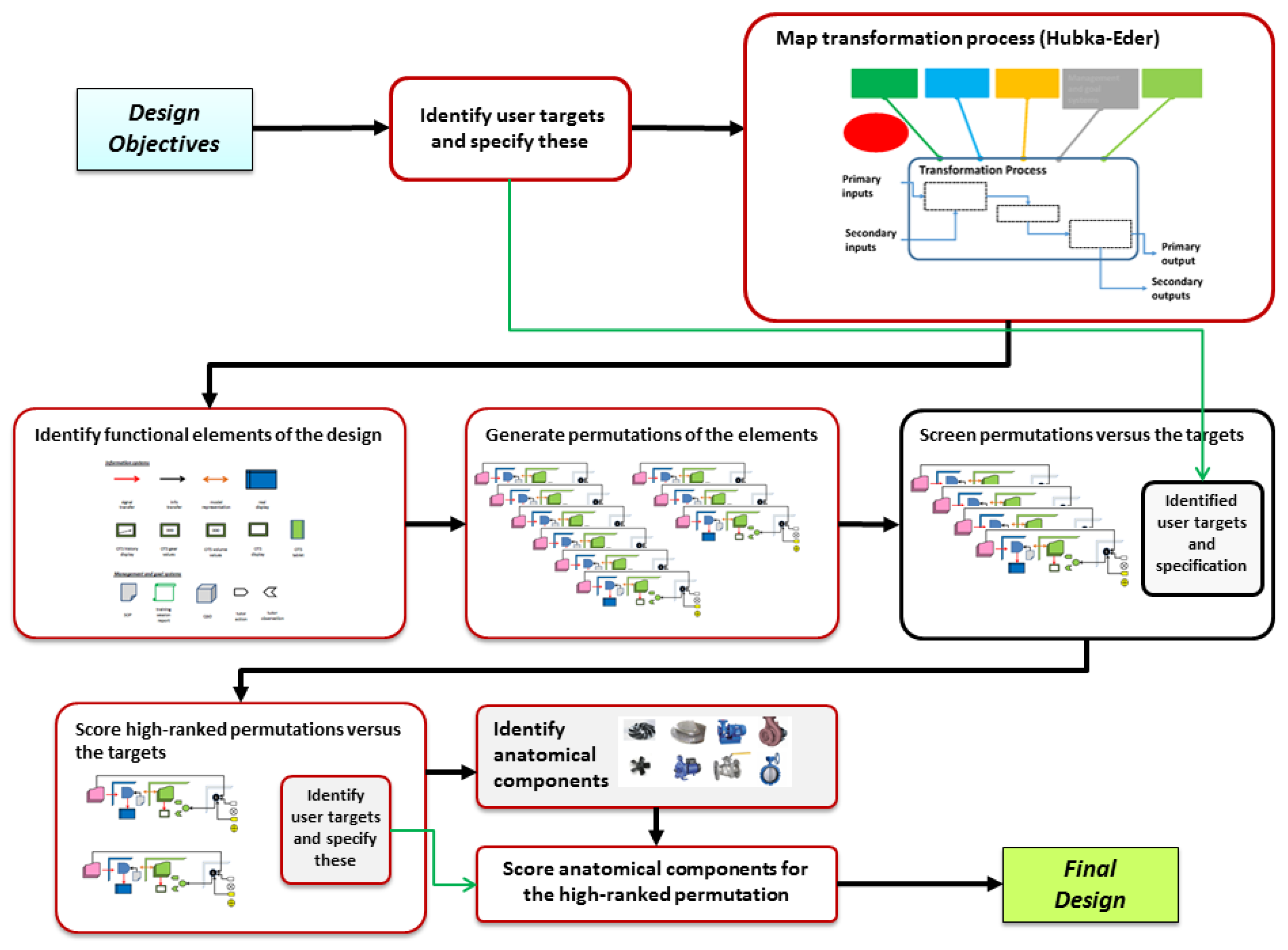
In the conceptual design methodology (
Figure 1) a so-called Hubka-Eder representation [
26] is used for analyzing and mapping the interdependencies of the intrinsic functions of the process.
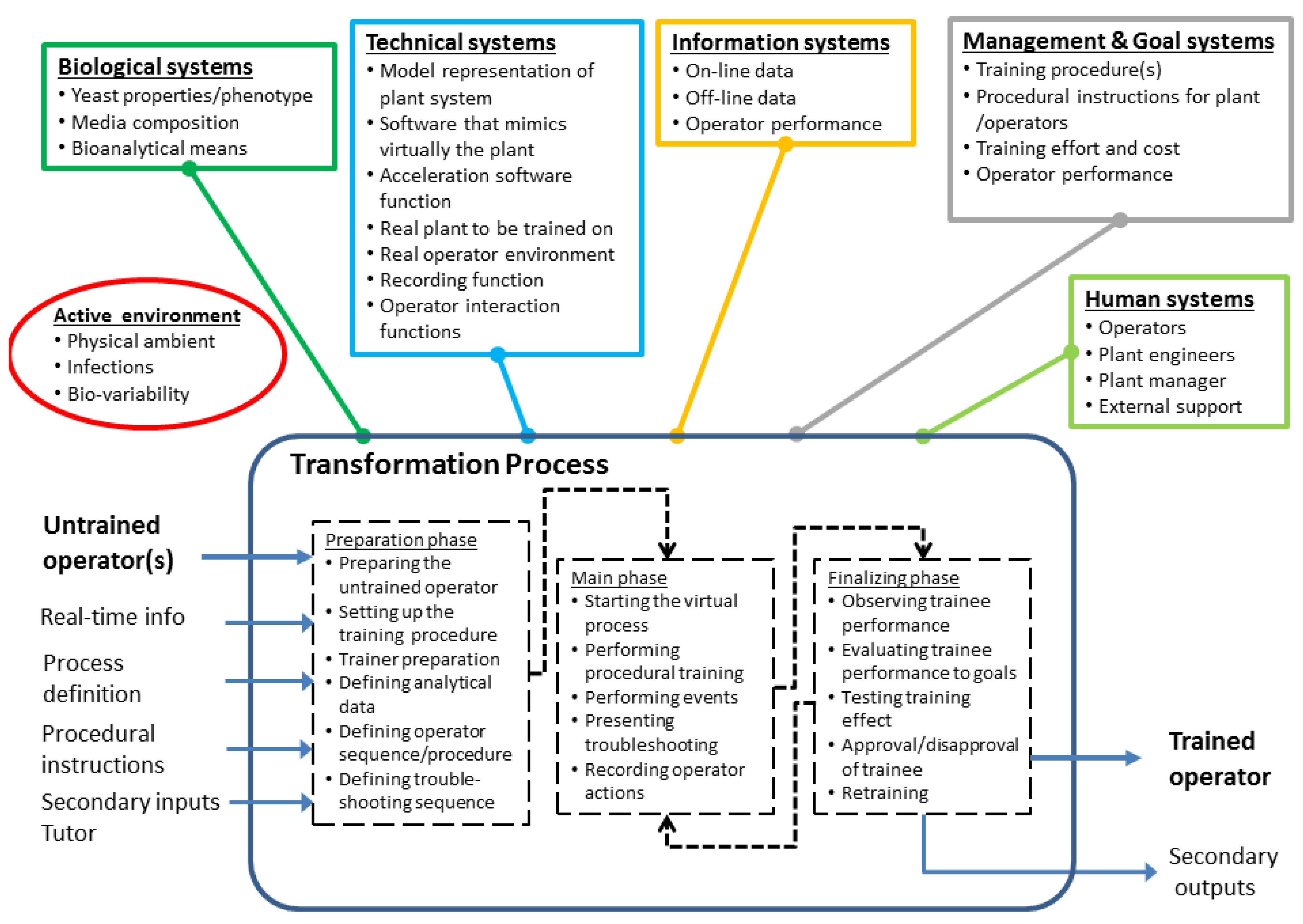
Figure 3 depicts such a map of the virtual OTS training in the plant.
The main feature of the OTS in the Hubka-Eder map is the transformation process (TrP). The TrP shows the training process and not the real bioprocess. Thus, the in- and outputs of the TrP of the OTS are distinctively different from the plant process.
In the transformation process, untrained operators become trained and more experienced. The training procedure includes specific training scenarios, such as start-up and shut-down of process units, adjusting conditions and performing diverse incidental actions. The training procedure can be divided into (1) preparation for training, mainly to get acquainted with the virtual environment of the training simulator, (2) performing procedural actions, and (3) finishing the training, e.g. by providing a report for evaluation by the trainer/tutor. Transfer-of-training [
30],
i.e., the acquired capability of the operator due to the simulation training, is the critical metrics of a successfully applied
TrP.
In the transformative training process, a set of functional systems are involved that are necessary for carrying out the
TrP [
31,
32]. These systems should encompass all kinds of functionalities that must interact with the
TrP or with each other for a successful performance of the process. The functions of the
biological systems (Σ
BioS) cover the enzymatic conversion of the starch raw materials to fermentable saccharides and the subsequent fermentation of these by yeast to ethanol. In addition, the raw materials are included in the Σ
BioS due to their biological origin as biopolymers in flour and starch. Thus, these functions are pivotal in the OTS representation of the process and key objects for the training.
Figure 3.
Hubka-Eder map representing the operator training of the bio-ethanol plant. The map shows both the systems involved in the plant as well as the systems for the OTS.
Figure 3.
Hubka-Eder map representing the operator training of the bio-ethanol plant. The map shows both the systems involved in the plant as well as the systems for the OTS.
The
technical systems (Σ
TS) include both the real bioprocess and the virtual representation in the OTS. They provide the spatial and temporal functions for the conversion by the biological systems of the raw material streams under defined physical and chemical conditions. Here, the components of the biological conversion are separated and concentrated by grinding, gravity, transport, vaporization and partitioning [
32,
33]. The Σ
TS also include the software functions that allow mathematical models to be computed in real time in the OTS as well as a function for accelerating the simulation. Typically, the functions of the technical systems can be realized with well-known technical equipment units such as bioreactors, continuous centrifuges, filters, heat exchangers and distillation columns as well as with computers and software of adequate capacity. Notably, the Hubka-Eder map is a functional diagram that has the purpose of identifying the functions needed for the transformation process, before making any decision on what particular technical solutions that should be chosen for realizing the functions.
The functions of the
information systems (Σ
IS) transform data from the technical and biological systems in formats useful for further interpretation and process control [
34]. The
management and goal systems (Σ
M&GS) provide instructions for the OTS training, e.g. standard operation procedures (SOPs) and incident operation procedures (IOPs), control setpoint values and other goals related to production. The
human systems (Σ
HS) represent all those individuals that are involved in the training and the production process,
i.e. the untrained operators, the trainer, experienced operators or plant engineers, the plant manager, the service teams of the OTS and of the plant itself—all providers of critical functions in the OTS training process.
In the Hubka-Eder map, an additional symbol, referred to as the
active environment, has the function of introducing into the map those events that inevitably happen but to large extent are unpredictable [
25]. This could be variation of the biological systems due to unknown oscillations of bioactivity, unwanted infections that have penetrated the sterile barriers of the equipment, variation of the raw materials and chemicals added to the process due to diverse suppliers, or power breakdowns in the plant.
The interactions of the systems and functions and how we understand the relationship between them are key design considerations [
26]. For example, how do the characters of the hydrolytic enzymes influence the design of the unit operations of the technical systems in terms of allowed physical ranges of states and parameters? How do the operating conditions of the units affect the choices of the information systems devices?
Special attention should be paid to the interaction between the systems and the active environment. What can happen due to the environment and how are the systems able to cope with that? And in particular, how do these activities set new objectives for the training?
Therefore, we emphasize the importance of distinguishing between functional representations, such as containment and cellular conversion, and physical or biological objects, such as reactors and cells. This is evident in the more detailed “zoom-in” maps of the functional systems (see
Figures S1–S3 in the Supplementary File).
Figure S1 details the Σ
TS of the OTS. These include the virtual representations of the plant units, the connections between units, meters and display functions, actuators, control loops, model functions of the process implemented in the software and the accelerator function for time. The subsystems shown interact with each other and provide information of the process and its response to operator actions as the Σ
IS notify the operator about.
Figure S2 shows a zoom-in of the Σ
BioS and indicates how functions and subsystems interact within and across systems.
Figure S3 does the same for the Σ
M&GS.
3.2. Specific Needs of Training of Plant Personnel
The general aims of the operator training were defined and constrained above. Based on these premises plant engineers and other responsible personnel were interrogated and encouraged to express needs, requirements and targets for training.
Table 1 compiles a first tier of needs as collected from the interrogations with the experienced plant expertise.
All needs were categorized into (1) training of the standard procedures, (2) incident training, (3) limited training of parts, (4) how to act to quality control (QC) data, (5) plant start-up and shut-down, (6) continuous mode of operation, (7) maintenance work, (8) interpreting control display data in relation to malfunctions, (9) training newly employed operator and continuing training. The objective of each need was converted to a target quantity in order to concretely specify the need.
However, in order to reach a precise fit of the conceptual design to the user’s demands and expectations on the OTS, more detailed descriptions and definitions of the needs are necessary as well as tighter specifications of the targets [
27]. This is provided in
Table S1, where complementary needs with target metrics are added in a second tier. These included the additional performance qualities of the training (reducing learning time of newly employed operators to 50%, decreasing mistakes after training, reducing requirement of using parallel operators), cost of training (investment, run time), needs of incidental training (start/stop plant due to maintenance, adjusting pH, dosage enzymes, power breakdown, change in feeding raw materials), trainer adaption (selection of incidences), continuing training, fidelity of real plant, and integrating manual actions in plant. The target metrics were expressed in terms of time, quality of training, degree of correct actions, time to working alone, amount of costs and level of detailed process description.
Table 1.
First tier of training needs of plant operators 1.
Table 1.
First tier of training needs of plant operators 1.
| Need category/need | Target |
|---|
| Training objectives | - |
| Shorter training period of new-employed operators | Training period is reduced by half |
| Reduced number of faulty actions | Faults are reduced by half |
| Shorter time to independence | New operator can work alone after 4 months |
| Advanced training for more experienced operators | The experienced operators shall meet increasing challenges that further improve operator skill |
| Improved understanding of the plant | A good understanding of the interdependences of flow and transformations |
| Training manual interaction with plant hardware | The direct interaction with valves out in the plant shall be trained virtually |
| Training sampling and actions from these | The operator shall become fully aware of when manual sampling/analysis is required |
| Technical features of OTS | - |
| OTS interfaces shall be very similar to real control system interfaces | 80% of the process flow charts on the plant’s own control shall be included |
| OTS shall deliver messages to the trainee | Alarm messages of events or change of values on OTS interface shall alert trainee realistically |
| Allowing training of standard procedures | The standard procedures for regular operation of the plant shall be included in the OTS |
| Allowing training of incidences | Up to ten common deviations and corrective actions shall be included in the OTS |
| Repetitive training possible | The acquired training shall be repeated at any time when it is desired |
| OTS shall be available for own use by operator | The operator shall be able to access and start up the OTS independently |
| OTS shall be possible to run in accelerated mode | The run time of the OTS shall be possible to accelerate up to 20-fold faster than real-time |
| Management of OTS | - |
| Plant manager/chief operator shall be able to handle and supervise the OTS training | The plant manager shall be able to monitor the trainees actions and adjust level of training |
| OTS software shall be adaptable and easy to update | The OTS shall be provided with update procedures that the plant engineers can maintain |
| Cost for OTS shall be modest | Investment shall not exceed other similar software |
| Standard PC shall be able to run the software | The computer hardware needed for the OTS shall require additional/items/communication cards |
Importantly, the need and target tables should be considered as “active” documents and may be expanded and modified based on growing knowledge and experiences of training. For example, emerging incidents can be added once such are considered necessary for training.
3.3. Functional Design Elements and Permutations
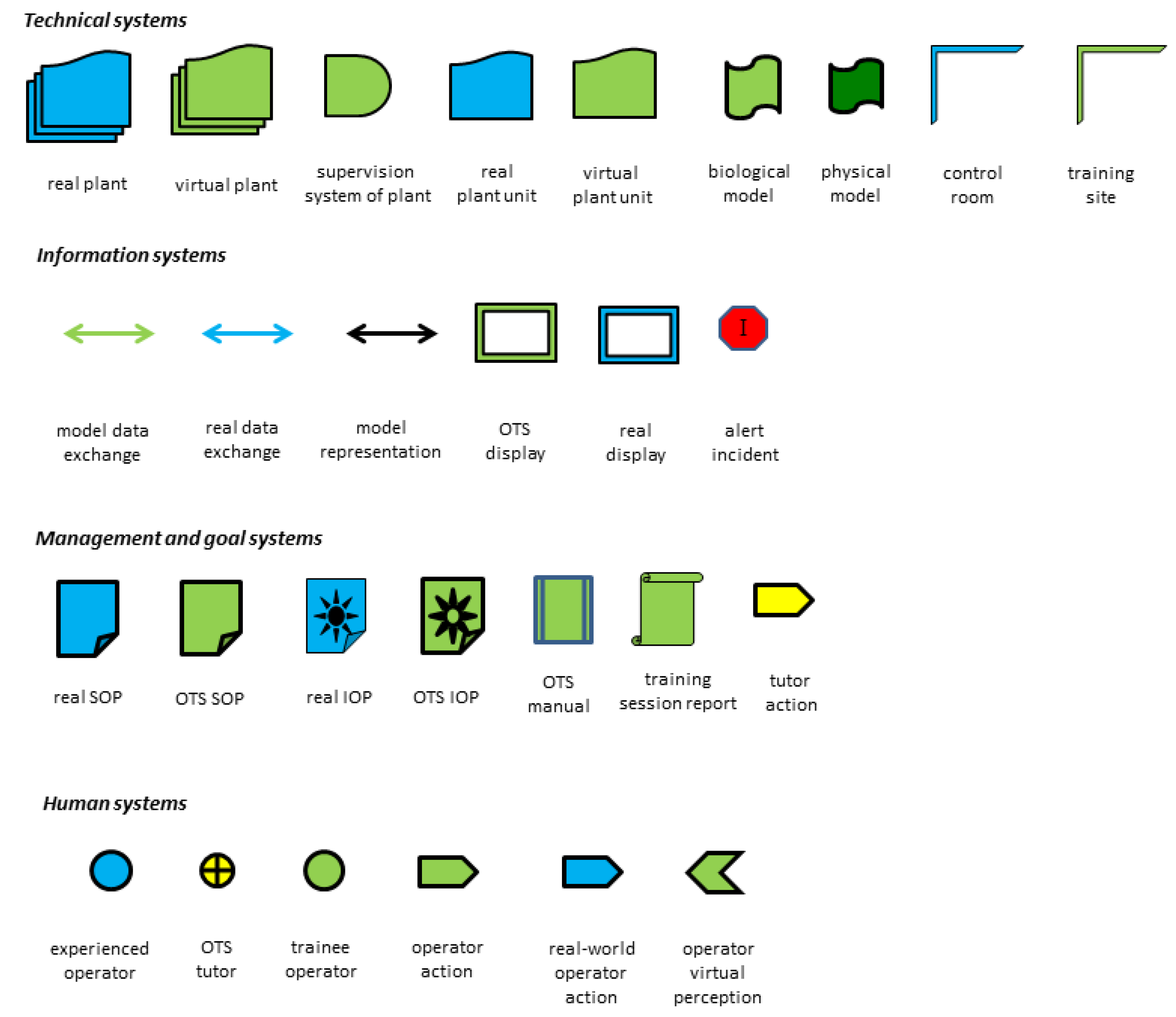
Required functional design elements for realizing an OTS according to the targets were derived from the systems in the Hubka-Eder map (
Figure 4 and
Figure S4).
Figure 4.
Functional elements of the training using the OTS of the bio-ethanol plant. These elements are to be used for considering diverse alternative configurations by permuting the elements. The elements are grouped according to the system they belong to in the Hubka-Eder representation.
Figure 4.
Functional elements of the training using the OTS of the bio-ethanol plant. These elements are to be used for considering diverse alternative configurations by permuting the elements. The elements are grouped according to the system they belong to in the Hubka-Eder representation.
Obviously, the ΣTS will generate the majority of the elements. These included the real bio-ethanol plant itself with its units, the real operator control system, the containments of the plant, the control room and its software, laboratories, the QC functions (e.g. laboratory, instruments), the software for the OTS, the training room/facility, the trainer room/facility, and the computer hardware. In addition, the humans involved represent a key category of functions in the Hubka-Eder representation, i.e., the trainees/operators to be trained, experienced operators, the responsible trainer and plant manager. The ΣIS include the information content per se transduced through the OTS to the operators on process events, analytical data from the QC lab, the operator interfaces in the bio-ethanol plant, and the display functions of the OTS (the graphical and data information of the OTS, the presentation of events, the action devices). The ΣM&GS include the SOP of the plant, the IOP, the training manual that instructs the operators how to carry out the training with the OTS, and the tutor’s training manual for running the operator training.
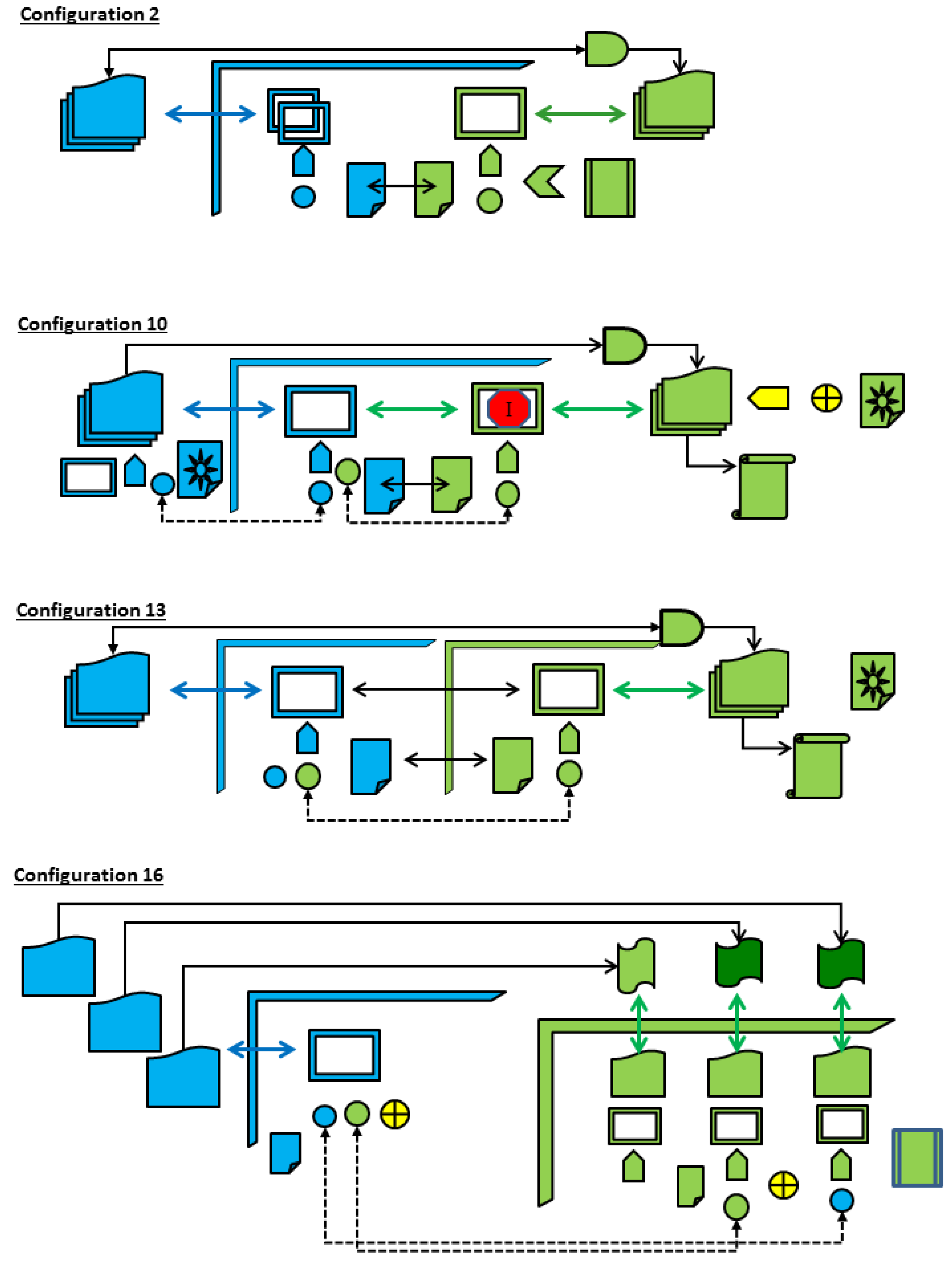
Figure 5.
A selection of four configurations using elements from
Figure 4 (a complete collection of configurations are found in
Figure S5). In Configuration 2 (from Category I) all training takes place in the control room of the plant. An un-supervised set-up where the control room been extended with several screens. OTS model is provided with an accelerator function to reduce training time. In Configuration 10 (from Category II) training takes place partly in the plant hall. Real incident occurs in real process and trainer reproduces this in the OTS interface for the trainee to act upon. In Configuration 13 (from Category III) training is carried out in a room aside the control room and the plant, here with a more advance training with models. In configuration 16 (from Category IV) a distributed simulator setup is configured from existing software programs with extended modeling and simulation capacity for selected parts of the plant. Independent unsupervised training in takes place in the plant hall.
![Processes 03 00664 g005]()
The active environment is a key function for representing unplanned and non-procedural events in the process during the training. As already mentioned, it spans from malfunctions of equipment, unanticipated variation in raw materials and biological activities, power breakdown, computer failures, etc.
Functional elements are either real or virtual—the real elements refer to the units in real large-scale bioprocess such as bioreactors and pumps, and the virtual elements to the OTS representations of these, such as digital objects for these units on the GUIs. Some of the elements may fall into more than one category but are shown here for only one of them. A critical feature of the OTS is its ability of establishing adequate and realistic virtual elements that represent the real functions.
Relationships between the functions and elements and their combinations were investigated in the design team by generating diverse configurations. By permuting the elements, a multitude of configurations are possible to set up. This part of the work depended much on the experience of the team. In addition, it was important to iteratively compare the configuration with the specified needs. Many of the theoretically possible configurations were obviously not matching and could directly be discarded.
Twenty variants of configurations were seemingly realistic to further analyze and compare towards the target needs (
Figure S5). These configurations fall into four main categories: configurations (I) where the OTS training takes place in the plant control room adjacent to the plant control system, (II) where the training is extended to also take place inside the real plant facility with additional site screens and controller units, (III) where the training takes place in a separate training room where the OTS and trainee are placed, and (IV) where the training is carried out with an OTS setup based on one or several standard simulation software on stand-alone PCs for each simulator application/plant unit.
Four configurations collected from the twenty configurations in
Figure S5 are displayed in
Figure 5. Each configuration represents one of the four categories (Configuration No 2 from category I, Configuration No 10 from category II, Configuration No 13 from category III and Configuration No 16 from category IV).
3.4. Evaluation versus Targets
The configurations were compared with the targets specified in user need tables. As recommended in the methodology [
22] the configuration alternatives are ranked
versus the needs’ target metrics (
Table 1). This screening is qualitative,
i.e., applies a course grading of how well the configurations meet the ambitions of the target metrics, or, if they even negates the purpose of the targets. It is up to the ingenuity of the design engineers to set up an evaluation team with the necessary experience and knowledge of the actual process. Importantly, the providers of the targeted needs should have a role in this, thereby representing accumulated knowledge of the plant.
Table 2 shows the outcome of the screening, here assessed at four levels; from no effect to high effect (-, ●, ●●, ●●●). The assessment depends much on the experiences and expertise involved and is an iterative process in the expert team. This is a crucial part in the design work that may need consultation by additional experts, comparison of various grading and check of robustness and sensitivity assessments. Summing up the marks shows that Configuration 10 best meets the training needs. By scrutinizing the score marks it becomes apparent what are decisive for the outcome of the alternatives.
Table 2.
Screening configurations versus training needs
Table 2.
Screening configurations versus training needs
| Need category/need | Configuration |
|---|
| 2 | 10 | 13 | 16 |
|---|
| Training objectives | - |
| Shorter training period of new-employed operators | ●●● | ●●● | ●●● | ●●● |
| Reduced number of faulty actions | - | ●●● | ●● | - |
| Shorter time to independence | ●● | ●● | ●●● | ● |
| Advanced training for more experienced operators | ●● | ●● | ●● | ●●● |
| Improved understanding of the plant | ●●● | ●●● | ●●● | ●●● |
| Training manual interaction with plant hardware | - | ●●● | - | - |
| Training sampling and actions from these | - | - | - | - |
| Technical features of OTS | - |
| OTS interfaces shall be very similar to control interfaces | ● | ● | ● | ● |
| OTS shall deliver messages to the trainee | - | ●●● | - | - |
| Allow training of standard procedures | ●●● | ●●● | ●●● | ●●● |
| Allow training of incidences | - | ●●● | - | - |
| Repetitive training possible | ●●● | - | ●●● | - |
| Adjustment of plant floor valves and meters | - | ●●● | - | - |
| OTS shall be available for own use by operator | ●●● | ●●● | ●●● | - |
| OTS shall be possible to run in accelerated mode | - | ●●● | ●●● | ● |
| Management of OTS | - |
| Plant manager shall handle and supervise OTS training | - | - | - | - |
| OTS software shall be adaptable and easy to update | ●●● | ●●● | ●●● | ● |
| Cost for OTS shall be modest | ●●● | ●●● | ●●● | ● |
| Standard PCs shall be able to run the software | ●●● | ●●● | ●●● | ●● |
| Total score | 29 | 44 | 35 | 19 |
For example, Configurations 10 and 13 are assumed to be more successful in reducing inadequate operator actions than Configurations 2 and 16. This assessment is based on the use of SOPs and IOPs in the training with defined description for incident actions. The trainee shall follow the written as well as oral instructions from an experienced operator that improves the quality of a training. Moreover, incident alerts expand the training complexity and prepare the trainee more efficiently to react to common and uncommon incidents correctly. In addition, the integration of the OTS system within the real control room allows better communication between the experienced operator and trainee. Shorter time to independence might be achieved with high effect applying Configuration 13 when the trainee is supposed to use the OTS and subsequently transfer learned skills to the real operational training under supervision. Configuration 10 also shows higher effects for technical features of the OTS where alarm messages, incident training and the integration of virtual and plant floor training are provided. In the shown configurations, there is no interaction with the plant manager, thus, the training is handled and supervised mainly by a senior operator. Configuration 16 represents a training set-up where plant data are directly transferred to the models of the OTS system and computed in a training session. Each plant unit is linked to an OTS where experienced operators are able to analyze and train process interactions that might be useful for process optimization. However, this configuration may require extensive, which might exceed the budget available for the OTS.
A more thorough scoring may be justified and could be done by involving additional target needs. By including the second tiers of needs and weighing the importance of these needs the outcome of the assessment was refined. Here, the scoring was set from 0 to 3 (-, ●, ●●, ●●●) and the weight-factor was either 1 or 2 or 3. All the twenty configuration alternatives, as shown in
Figure S5, were included in the scoring. The outcome of different scorings is shown in
Tables S2-S4. Obviously, the criteria for scoring are decisive. If certain needs are weighed differently, the score of a configuration may change its priority.
In
Tables S2–S4, three examples of weight-factor sets are shown: one where all needs are weighed equal, one where cost of training is more essential, and one where process understanding is more essential. In these cases, the scoring outcome is not changed and the assessment appears robust. Clearly, the developers have this choice in their hands and can decide according to their priorities. Therefore, it is advisable at this stage to consult the customers’ views again. What are their preferences? Priorities in the starting phase with general specifications may in the more concrete final phase have changed.
In addition, other preferences were noted. The preferred OTS design should have a high degree of self-management by the trainee, can be switched on for shorter training, is placed close to but not in the control room, and can be adapted by a local tutor password protecting the list of incidents.
Table 3.
Operational procedures as part of an OTS training manual.
Table 3.
Operational procedures as part of an OTS training manual.
| Number | Procedural step | Purpose/Details |
|---|
| 1 | Define training aim | Training procedures clearly defined and adapted to the trainee’s knowledge (apprentice, experienced) |
| 2 | Starting the OTS | Setting configurations of the OTS including training starting point (starting a new batch, continuous processing, incident training), incident definition and the time when a certain incident should occur |
| 3 | Setting acceleration of simulation speed | Degree of acceleration mode is set based on trainee’s capability to control the process |
| 4 | Sequential steps in running a production process unit | The sequence of operational steps for each process unit are described and instructions for what actions should be taken are given |
| 5 | Sporadic acceleration | An acceleration feature allows sporadic acceleration of an already defined acceleration mode in order to allow e.g. a faster filling and heating of a tank during a start-up procedure |
| 6 | Performance reports | Procedures for displaying and compiling reports |
| 7 | Tutor settings | Tutor can evaluate the trainee’s performance |
| 8 | Transfer-of-training | Learned experiences are transferred to the real system and the training progress is assessed |
| 9 | Repetitive training | Training procedures can be repeated when it is required |
Importantly, the training should be performed by using a training manual where the trainee is taken through the sequence of actions stepwise through written instructions, e.g. with procedures for start-up, shut-down and continuous operation of the plant (
Table 3). The GUI of the OTS should present messages to the trainee that inform about process events, incidents and other required actions. Sometimes the events should be inferred by the trainee without specific commands, sometimes they are inevitably imperative such as a defect pump. All these training procedures are documented in the training manual for repeated use. The trainee can use these instructions independently or as advised by an experienced operator or plant training manager.
The actions and performance of the trainee should be recorded by the OTS in a report to the tutor. The software allows a variety of technical solutions to be implemented for this purpose. From that report the tutor can continuously adapt the training based on learning progress. Reports might be the process history diagrams in combination with an action-log, showing e.g. manual adjustments of pump rates that are available after a training.
Based on the preferred OTS configuration the actual physical structural form, of it is constructed and implemented. The particular software used has here not been included as a critical design criteria as the programming modules are alike in most commercial software.
3.5. Remarks on the Subsequent Implementation for Realizing the Conceptual Design of the OTS
The main tool for realizing the conceptual design is the software platform. Examples of such platform alternatives are the ASPEN software (Aspen Technology, Inc., Bedford, MA, USA), Wonderware (Schneider Electric Software, Lake Forest, CA, USA), G2 (Gensym, Burlington, MA, USA), SIMATIC PCS 7 (Siemens AG, Munich, Germany), LabVIEW [
35,
36,
37,
38] and WinErs (Schoop GmbH, Hamburg, Germany). Applications with bio-ethanol production plants have previously been reported for these software [see e.g. 38]. In this study, the WinErs software was used [
29].
Concerning computer hardware details, such as capacity of the processors of the hardware necessary for the size of the OTS application and its display functions (screen size, resolution, display devices, e.g. desktop, lab-top or portable tablet variants) must also be compared.
In principle, the technical specifications of the computer software and hardware can be compared in order to rank their capacity in complying with the OTS functions and the user targets. This has, however, not been included in this study.
The OTS software and model description will be detailed in other reports by us as it is a wide issue
per se and therefore not discussed in this article [
39]. Presently, the OTS software is validated at the Reppe bio-ethanol plant.
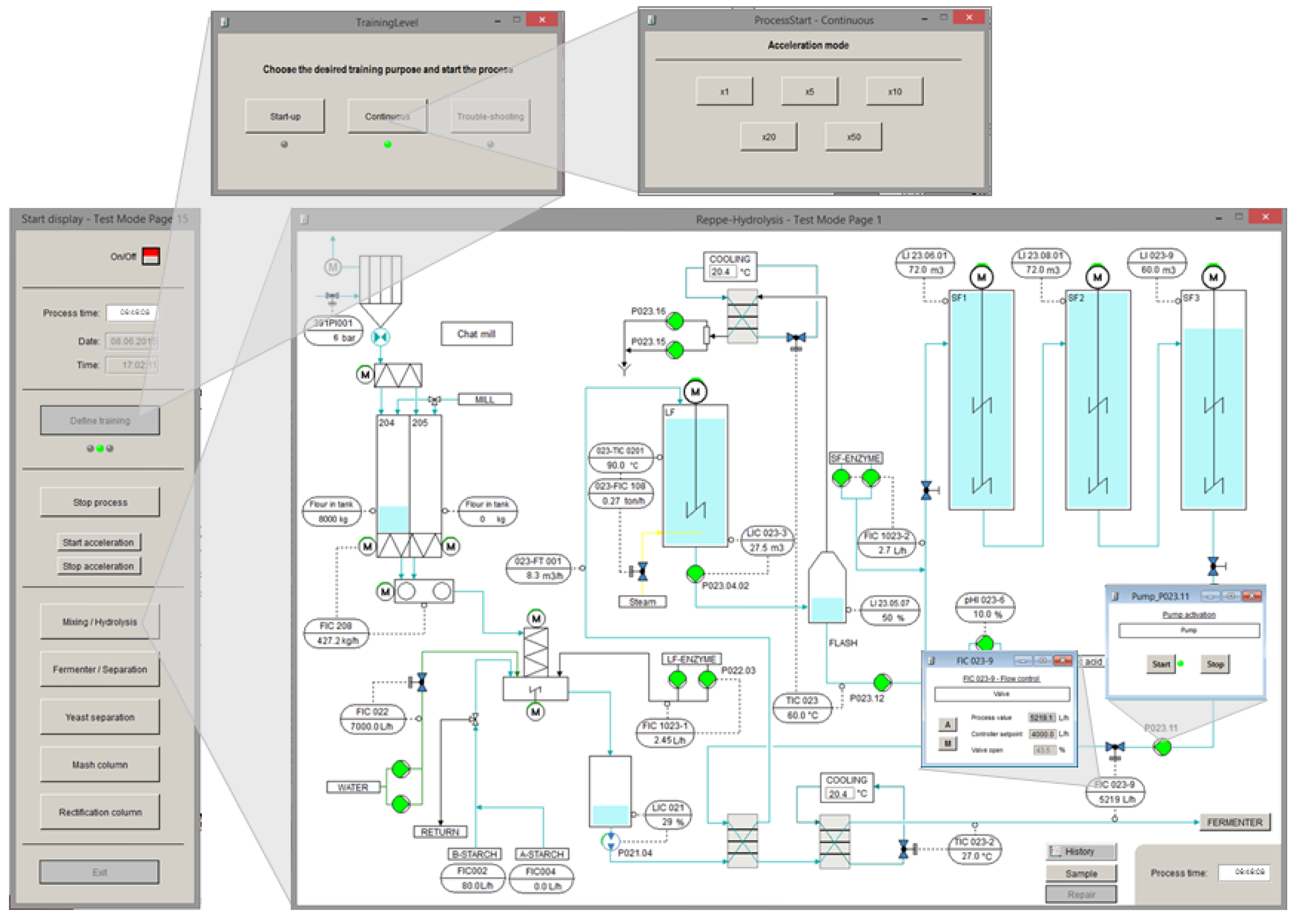
Figure 6 and
Figure 7 show examples of the implementation of the GUIs for the designed OTS hydrolysis and fermentation sections of the bio-ethanol plant. The control and measurement points in in these figures mimic accurately the DCS of the real plant. Identical control sub-windows can be opened in the OTS in order to change control setpoints as well as automation (A) and manual control (M) modes.
Figure 6.
Example of GUIs of the OTS as designed from the conceptual design premises. The figures shows the hydrolysis process section of the virtual plant with sub-windows (above and inside main window) for start/stop, settings of valves and pumps that are comparable to the real DCS. An additional start-window (left) displays key features of the OTS including the visualization of the virtual process time. Via different buttons the user can define the training configuration and the acceleration mode, as well as open additional GUIs, e.g. for changing the acceleration.
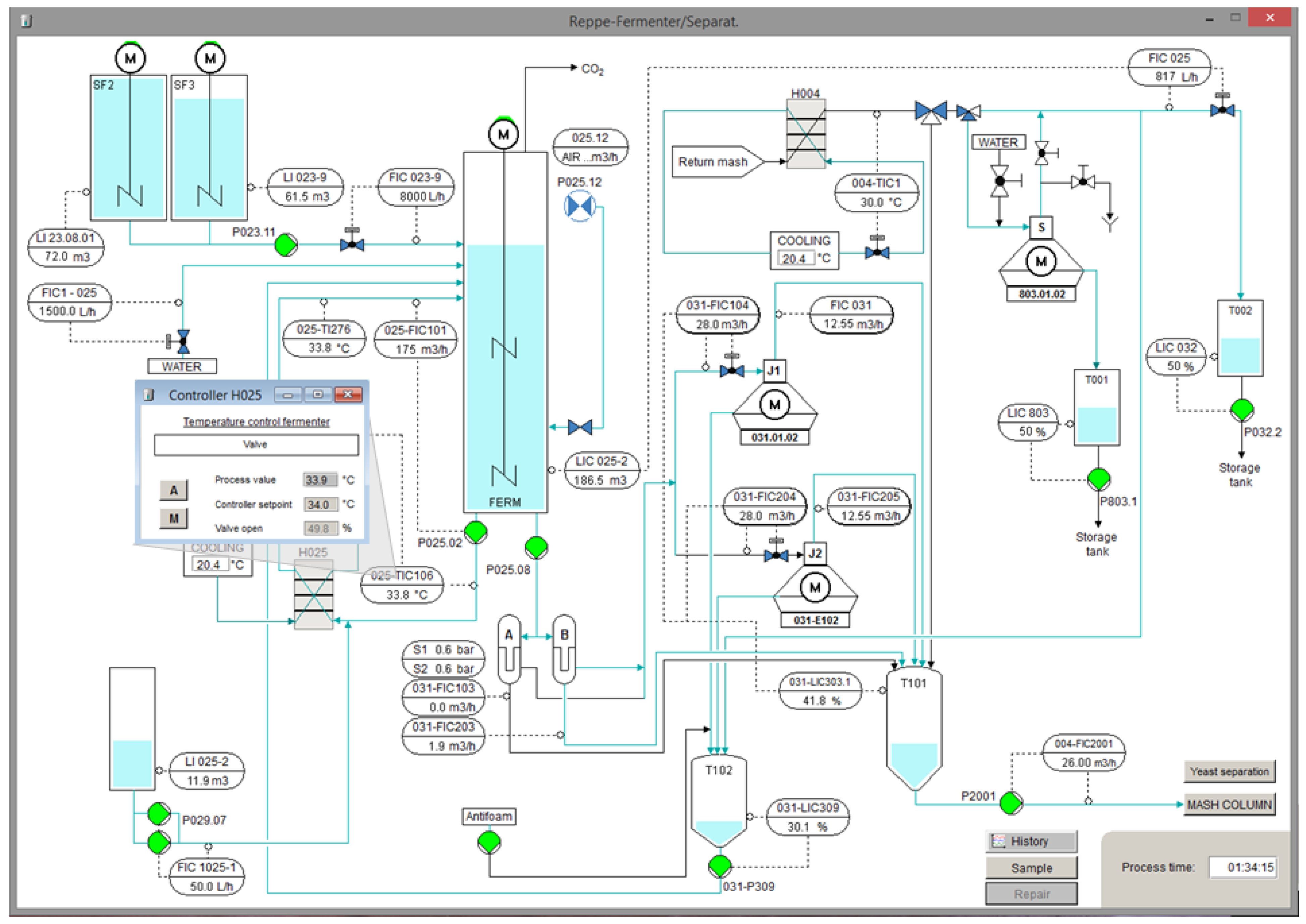
Figure 7.
Additional example of a GUI of the OTS as designed from the conceptual design premises. The figure shows the fermentation process section of the virtual plant with a controller sub-window for cooling of the broth. Sampling for off-line analysis can be initiated via the button “Sample”. The analytical results are then displayed in a data table window for e.g. pH and concentrations of glucose and dry mass (not shown in figure).


