1. Introduction
Previous work has demonstrated that renewable transportation fuels can be derived from fatty acid and triacyl glyceride (TAG) based oils, such as crop oils, bacteriological lipids, and algae oils [
1]. Along with the well-established processes for biodiesel production [
2], alternative processes are currently entering the marketplace that convert these oils into other fuels, such as jet fuel [
3] and green diesel [
1,
4]. The margins for these processes are challenging as the competing petroleum refining industry is extremely efficient. One strategy to increase the economic fidelity of such processes is to produce a diversity of co-products, preferably with high values, leading to higher overall profit margins for the facilities.
Non-catalytic cracking leads to a number of such co-product options, including high purity carbon, aromatics, and short chain fatty acids [
5]. Kubatova,
et al. [
6] found that the non-catalytic cracking of canola and soybean oils results in 15 wt%–25 wt% C2–C10 linear saturated monocarboxylic acids. These acids have market values that range from comparable to transportation fuels (C2: acetic acid) to many times the value of fuels (C7–C10). Previous work [
7,
8] demonstrated that these acids can be separated from the alkanes, aromatics, and other constituents in the cracking reaction outlet liquid product. However, the question remained, “can products be generated that have sufficient purity for use in downstream product applications?” Thus the goal of the work documented here was to demonstrate one such product.
This goal was accomplished through the sponsorship and guidance of a major international chemical company, Kuraray America. In this work, commercial quality vinyl acetate monomer (VAM), which is the monomer used to produce polyvinyl acetate and other high-volume commodity materials [
9,
10], was produced from one of the most common of the short chain fatty acids, acetic acid.
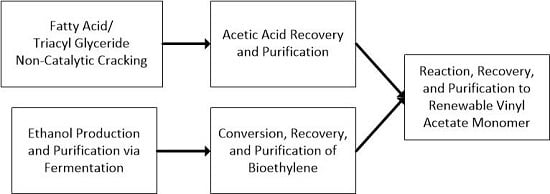
Figure 1 shows a simplified process scheme for those portions of a commercial facility that would be utilized to produce VAM. Soybean oil, a triacyl glyceride-based oil, is non-catalytically cracked and an organic liquid product (OLP) is recovered from the reaction products. Acetic acid is then extracted out of the mixture using an amine solvent and purified. The purified acetic acid is then reacted with ethylene and oxygen to form the VAM product.
Figure 1.
A simplified process scheme for the production of vinyl acetate monomer from a fatty acid or triacyl glyceride-based oil via non-catalytic cracking.
Figure 1.
A simplified process scheme for the production of vinyl acetate monomer from a fatty acid or triacyl glyceride-based oil via non-catalytic cracking.
The largest user of acetic acid is the vinyl acetate monomer (VAM) manufacturing industry. VAM is the basis of white glue, laminating wallboard, and latex paint. Polymers derived from VAM are used in safety glass, film products, and hot-melt adhesives [
11]. Although recent work has focused on alternative methods [
12], most VAM is produced by the oxidative addition of acetic acid to ethylene over palladium (Pd) based catalysts [
13] as shown in Reaction (1):
This is an exothermic reaction with a standard heat of −176.2 kJ/mol [
14]. Therefore, it is necessary to remove thermal energy during the reaction to maintain isothermal conditions.
Due to the presence of oxygen in the reactor, oxidation of ethylene can occur as an undesirable side reaction. This oxidation reaction is shown in Reaction (2):
This reaction has a high heat of reaction, −1322.8 kJ/mol, so it can complicate thermal energy removal [
15]. The reaction also consumes the oxygen and ethylene that are meant for VAM production. For these reasons, this side reaction must be kept to a minimum.
Fortunately, the VAM Reaction (1) has a much lower activation energy, 30.5 kJ/mol, than the oxidation Reaction (2), 84.1 kJ/mol [
15]. Thus, keeping the reactor temperature sufficiently low will reduce the rate of Reaction (2) relative to the rate of the Reaction (1). Also, since oxygen is a 3rd order reactant in Reaction (2) and only a half-order reactant in Reaction (1), keeping the O
2 concentration low helps to reduce the rate of ethylene oxidation. An O
2 concentration of less than 8% will also prevent an explosive mixture of ethylene and oxygen [
16]. The need for such a low concentration of oxygen generally leads to low single pass conversions in the desired reaction.
Industrially, both gas and liquid phase reactions are used, but the gas phase alternative is much more common. The reaction is performed industrially using either a packed bed reactor (PBR) or a fluidized bed reactor [
14]. The reaction is typically embedded within a large recycle loop [
16]. Typically the reactor feed contains about 2–3 times the stoichiometric requirements for ethylene, but only about a quarter of the oxygen needed to convert the acetic acid to VAM. Therefore, oxygen is the limiting reactant. Single pass conversions for acetic acid and ethylene do not typically exceed 20% and 10%, respectively [
14]. After the reactor effluent is cooled the product gases and liquids are separated using a knockout drum. Each stream is then processed further to recover unreacted feedstocks.
In the present work, a simplified scheme was followed which is more amenable to lab-scale implementation. Differences in this scheme from that outlined above are described in section 3, Experimental Methods, below.
2. Materials and Experimental Systems
2.1. Materials
Food grade soybean oil for thermal cracking was purchased from Columbus Oil (Chicago, IL, USA). Isobutyl acetate for the azeotropic distillation step was purchased from Sigma-Aldrich Co. (St. Louis, MO, USA) and was 98% pure. Non-renewable acetic acid, which was used during commissioning and optimization of the VAM reaction steps, was at least 99.7% pure and was purchased from VWR International (Radnor, PA, USA). Palladium-gold catalyst was provided by Evonik Industries (Parsippany, NJ, USA).
Although ethylene is also a by-product of TAG oil non-catalytic cracking, the present work focused on renewable acetic acid generation. Both renewable and non-renewable ethylene were used in the second reaction step to form the VAM. Renewable ethylene can be produced from ethanol by dehydration over a catalyst at high temperatures [
17] or by a proprietary process involving a butylene intermediate developed by Braskem [
18,
19]. Oxygen and non-renewable ethylene were both 99.9% pure and were purchased from Praxair Inc. (Danbury, CT, USA). Renewable ethylene was produced by Braskem for Kuraray America (Houston, TX, USA) to a 99.9% purity from ethanol at Braskem’s plant in Triunfo, Rio Grande do Sul, Brazil.
Analytical standards and solvents (methanol, butanol, acetic acid, propionic acid, butanoic acid, and pentanoic acid) were purchased from Sigma Aldrich (St. Louis, MO, USA) and were all 98.5% pure or greater. Vinyl acetate standard was purchased from VWR international (Radnor, PA, USA and was 99% pure. Chromatography gases–helium, hydrogen, argon, and air–were all obtained from Praxair (Danbury, CT, USA) and were 99.999% pure unless otherwise specified.
2.2. Experimental Systems
A series of lab-scale systems were used to replicate the processing scheme shown in
Figure 1. Both reaction steps were performed using continuously operated systems, while the extraction and purification steps employed both continuous and batch processing systems. Each major step was performed separately so the quality of the intermediates could be analyzed and optimized prior to performing the next step.
The most significant difference from the flow scheme shown in
Figure 1, was the use of water as the fatty acid extraction solvent (following Ghandi
et al. [
7]) rather than an amine (as per Braegelmann
et al. [
8]). Amines allow nearly complete extraction of all of the fatty acids in the mixture [
8] whereas hot water is only very efficient for acetic acid [
7]. Since we were only interested in utilizing the acetic acid by-product in this project, use of water simplified the downstream purification steps compared to using an amine. Commercially, it would make more sense to extract all of the fatty acids and then purify those that are commercially attractive into high value chemical products with the remaining fatty acids deoxygenated to alkanes and used in fuel products.
In the present work, a two phase mixture was produced from soybean oil in a non-catalytic cracking reactor and then separated into four phases: A non-condensable gas phase, an aqueous liquid phase, an organic liquid product phase (the dominant phase), and a heavy organic liquids phase. Short chain fatty acids were extracted from the organic liquid product phase via extraction into water. A nearly pure acetic acid stream was produced by azeotropic distillation and combined with the aqueous liquid phase from the cracking reactor which was nearly pure acetic acid. A final distillation step was performed to reach the target acetic acid purity of 98 wt%. The renewable acetic acid was reacted with oxygen and ethylene over a Pd-Au catalyst to produce VAM. The VAM was recovered from the unreacted feed materials, which were then recycled to the reactor.
The specific lab-scale systems used for each of these steps is described below.
2.2.1. Feed Oil Cracking
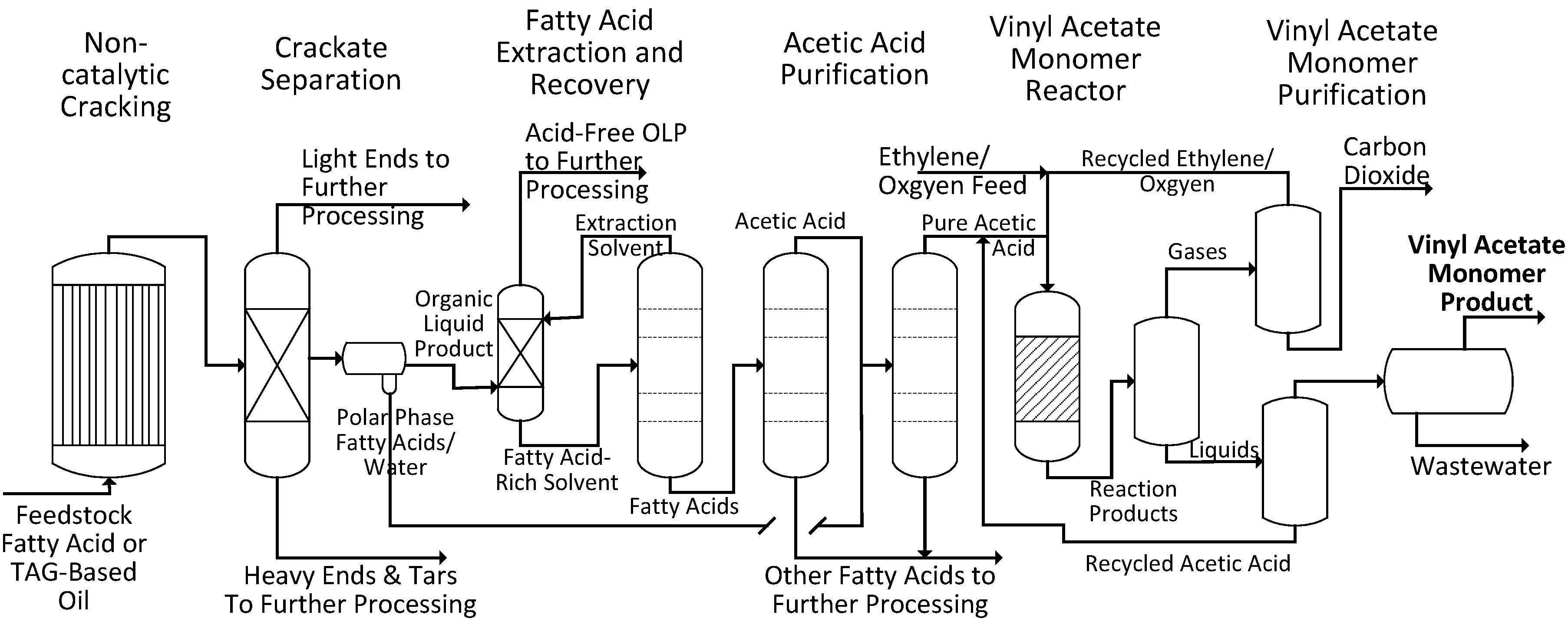
Non-catalytic cracking was carried out in a small pilot-scale 2 L/h continuous tubular reactor held in an insulated ceramic enclosure containing electric heating elements with a total heat output of about 6000 W, as shown in
Figure 2. Soybean oil was routed through two preheaters and then fed to the reactor using a Neptune model 515-A-N3 proportioning pump. The tubular reactor consisted of 16 sections of 1.5 m long 0.95 cm diameter Inconel 625 tubing. The tubes were connected by manifolds on both ends so that the oil would flow through 24.4 m of tubing while being cracked. The temperature was monitored using eight thermocouples in the enclosure and three thermocouples in the fluid. Fluid temperature was controlled via LabVIEW (National Instruments, Austin, TX, USA) by regulating the current supplied to the heating elements. The reactor pressure was monitored using PX309-1KG5V pressure transducers (Omega Engineering Inc., Stamford, CT, USA). Reactor pressure was maintained manually using a back-pressure regulator (Swagelok, Solon, OH, USA) and products were condensed and cooled using a shell and tube heat exchanger with a high flow rate of cold water before collection in the product tank.
Figure 2.
Diagram (a) and photo (b) of the University of North Dakota’s pilot scale continuous tubular non-catalytic cracking reactor.
Figure 2.
Diagram (a) and photo (b) of the University of North Dakota’s pilot scale continuous tubular non-catalytic cracking reactor.
2.2.2. Cracking Product Liquid Distillation
The liquid collected in the product tank of the cracking reactor was distilled continuously in an insulated 1.83 m tall, 10.2 cm diameter distillation column packed with 1.27 cm ceramic rings as shown in
Figure 3. The column’s feed was approximately 0.91 m from the bottom of the column. An electric heat source was wrapped around the bottom 15 cm of the column. The overhead temperature was monitored using a thermocouple in the vapor phase distillate stream and controlled by varying the heat supplied in the bottom of the column. Distillates were condensed in a water cooled heat exchanger and recovered in a distillate receiver drum. The bottom of the column was operated in a semi-batch manner. A valve was opened to allow the bottoms product to flow out when the level in the column reached 0.3 m, which was indicated by a side draw. The aqueous phase from the distillate stream was decanted off of the organic phase using a separatory funnel.
Figure 3.
Schematic of the UND bench-scale continuous crackate distillation column.
Figure 3.
Schematic of the UND bench-scale continuous crackate distillation column.
2.2.4. Azeotropic Distillation of Aqueous Acetic Acid
The first purification step was accomplished through the removal of water by azeotropic distillation using isobutyl acetate (IBA) as an entraining agent for water. This distillation was carried out in a lab-scale distillation apparatus with a 5 L round bottom pot flask and a 30.5 cm tall, 2.5 cm diameter glass column packed with 0.64 cm ceramic rings as shown in
Figure 4. The distillate was condensed using a water-cooled glass condenser, and then entered a separatory funnel where water was removed while IBA was periodically refluxed into the distillation column using a peristaltic pump. Waste water from the separatory funnel was disposed.
Figure 4.
Diagram of the initial acetic acid recovery step using a lab-scale recycle distillation system.
Figure 4.
Diagram of the initial acetic acid recovery step using a lab-scale recycle distillation system.
Figure 5.
Diagram of the automated spinning band distillation system used for the second step in the acetic acid recovery process.
Figure 5.
Diagram of the automated spinning band distillation system used for the second step in the acetic acid recovery process.
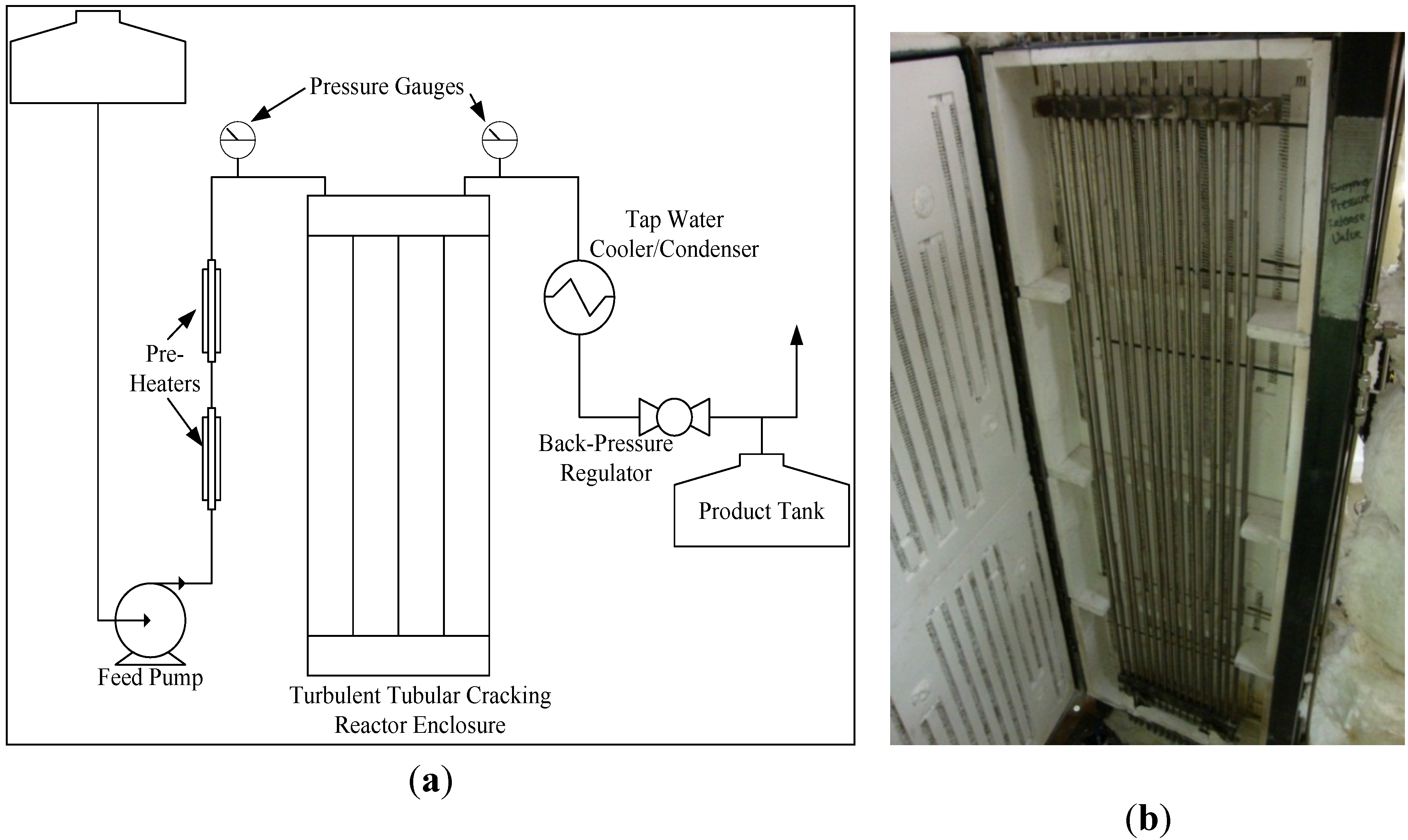
The second purification step was performed using a High Efficiency Distillation System (Model 18–100, B/R Instrument, Easton, MD, USA) as shown in
Figure 5. The distillation column was equipped with a Teflon spinning band capable of producing up to 200 factory reported stages of separation. An 8 receiver fractionating carousel was used to automatically collect fractions based on overhead temperature.
The spinning band distillation system shown in
Figure 5 was also used to separate VAM from acetic acid and wastewater (the final step shown in
Figure 1).
2.2.5. VAM Production
The VAM reactor system is shown in
Figure 6. The reaction vessel consisted of a 2.5 cm diameter, 35.5 cm long tubular packed bed reactor jacketed with a 5 cm diameter shell for water cooling. Acetic acid was fed using a high pressure positive displacement pump with a maximum flow rate of 10.0 mL/min. Gas phase reactants and inerts were fed through thermal mass flow controllers and all reactant streams were mixed together before entering the reactor. Both utility water and process streams were pre-heated in 0.64 cm steel tubing coils inside insulated ceramic enclosures containing electric heating elements. Both utility and process streams were also cooled after the reactor using water-cooled heat exchangers.
Figure 6.
The VAM reaction system.
Figure 6.
The VAM reaction system.
Temperatures in the process and utility streams were monitored before and after the reactor using k-type thermocouples. Reactor temperature was measured using a thermocouple inserted directly into the bed, and controlled by the back-pressure of the water/steam jacket. Utility water was heated to near saturation before entering the jacket, at which point the heat of reaction would vaporize some of it to steam.


